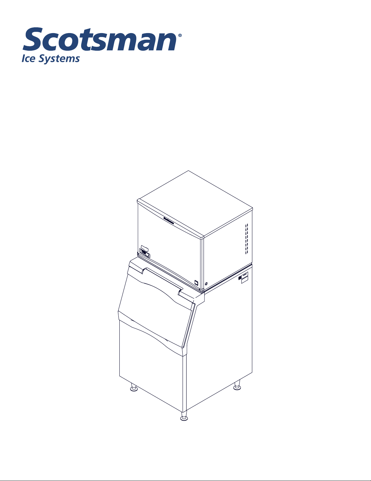
Installation and User’s Manual for
Modular Flake and Nugget Ice Machines
Prodigy Plus A Series Models
NH2030, NS2030, FS2330
Water Cooled and Remote Air Cooled

NH2030, NS2030, FS2330
A Series Water and Remote User Manual
November 2020
Page 1
Introduction
This ice machine is the result of years of experience
with aked and nugget ice machines. The latest in
electronics has been coupled with the time tested
Scotsman aked ice system to provide reliable ice
making and the features needed by customers. The
features include easily accessible air lters, simple
conductivity water level sensing, evaporator clearing
at shut down, photo-eye sensing bin control and the
ability to add options.
Contents
Installation: ..................................................................... 2
Location: ....................................................................... 3
Cabinet Layout .................................................................. 4
Unpacking & Install Prep ........................................................... 5
Water - Remote or Water Cooled .................................................... 6
Electrical ....................................................................... 7
Refrigeration - Remote Condenser Models ............................................. 8
Remote Condenser Location - Limits ................................................. 9
For The Installer: Remote Condenser ................................................. 10
Line Set Routing and Brazing ....................................................... 11
Final Check List .................................................................. 13
Initial Start Up and Maintenance ..................................................... 14
Maintenance: Scale Removal and Sanitation ........................................... 15
Maintenance: Scale Removal and Sanitation Continued .................................. 16
Options ........................................................................ 17
What to Do Before Calling for Service ................................................. 18
NH2030, NS2030, FS2330
A Series Water and Remote User Manual
November 2020
Page 2
Installation:
This machine is designed to be used indoors, in a
controlled environment. Operation outside the limits
listed here will void the warranty.
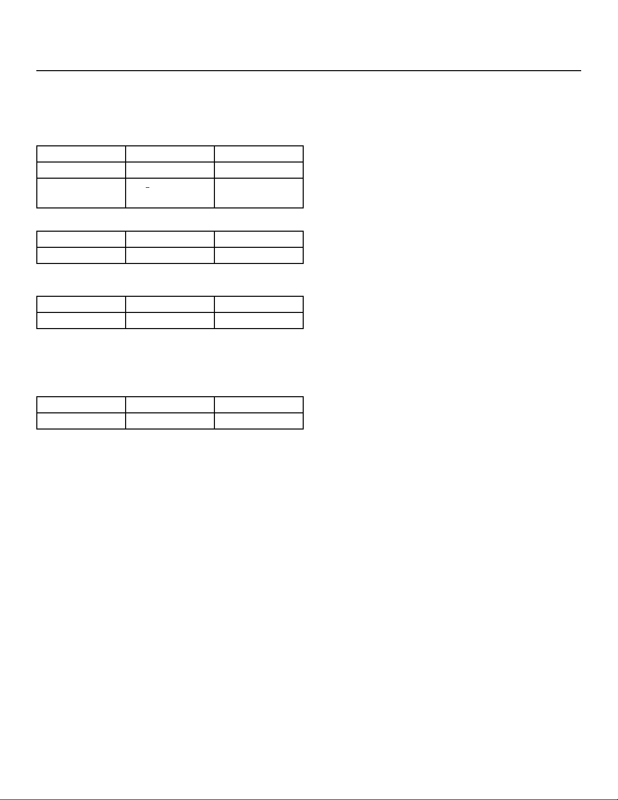
Air temperature limits
Minimum Maximum
Ice maker 50oF. 100oF.
Remote
condenser
-20oF. 120oF.
Water temperature limits
Minimum Maximum
All models 40oF. 100oF.
Water pressure limits (potable)
Maximum Minimum
All models 20 psi 80 psi
Water pressure limit to water cooled condenser is 150
PSI
Voltage limits
Minimum Maximum
208-230 60 Hz 198 253
Minimum conductivity (RO water)
• 10 microSiemens / CM
Water Quality (ice making circuit)
• Potable
The quality of the water supplied to the ice machine
will have an impact on the time between cleanings
and ultimately on the life of the product. Water can
contain impurities either in suspension or in solution.
Suspended solids can be ltered out. In solution
or dissolved solids cannot be ltered, they must be
diluted or treated. Water lters are recommended
to remove suspended solids. Some lters have
treatment in them for dissolved solids.
Check with a water treatment service for a
recommendation.
RO water. This machine can be supplied with Reverse
Osmosis water, but the water conductivity must be no
less than 10 microSiemens/cm.
Potential for Airborne Contamination
Installing an ice machine near a source of yeast
or similar material can result in the need for more
frequent sanitation cleanings due to the tendency of
these materials to contaminate the machine.
Most water lters remove chlorine from the water
supply to the machine which contributes to this
situation. Testing has shown that using a lter that
does not remove chlorine, such as the Scotsman
Aqua Patrol, will greatly improve this situation.
Warranty Information
The warranty statement for this product is provided
separately from this manual. Refer to it for applicable
coverage. In general warranty covers defects
in material or workmanship. It does not cover
maintenance, corrections to installations, or situations
when the machine is operated in circumstances that
exceed the limitations printed above.

NH2030, NS2030, FS2330
A Series Water and Remote User Manual
November 2020
Page 3
Location:
While the machine will operate satisfactorily within the
air and water temperature limits, it will operate more
eciently when those temperatures are nearer the
lower limits. Avoid locations that are hot, dusty, greasy
or conned.
Options
Ice is made until it lls the bin enough to block an
infrared light beam inside the base of the machine. A
eld installed kit is available to adjust the maintained
ice level lower. The kit number is KVS.
The standard controller has excellent diagnostic
capabilities and communicates to the user through the
AutoAlert light panel, seen through the front panel.
Field installed kits are available that can log data and
provide additional information when the front panel is
removed. That kit number is KSBU. A similar kit adds
network connectivity, and its number is KSBU-N.
Bin Compatibility
All models have the same footprint: 30 inches wide
by 24 inches deep. Conrm available space when
replacing a prior model.
Bin & Adapter List
• B330P or B530P or B530S – Direct t, no adapter
needed
• B842S – KBT22
• B948S – KBT28
• BH1100, BH1300 and BH1600 – upright bins
include ller panels to accommodate a single 30”
wide ice machine. No adapter is needed.
• BH1300 and BH1600 – KBT54 for two 30” units side
by side
Dispenser Compatibility
Only nugget ice models may be used with ice
dispensers. Flaked ice is not dispensable.
• ID200 – use KBT44 and KNUGDIV and KVS
• ID250 – use KBT44 and KNUGDIV and KVS
See sales literature for other brand model ice and
beverage dispenser applications.
Other Bins & Applications
Note the drop zone and ultrasonic sensor locations in
the illustrations on the next pages.
Scotsman ice systems are designed and
manufactured with the highest regard for safety and
performance.
Scotsman assumes no liability of responsibility of
any kind for products manufactured by Scotsman
that have been altered in any way, including the use
of any part and/or other components not specically
approved by Scotsman.
Scotsman reserves the right to make design changes
and/or improvements at any time. Specications and
design are subject to change without notice.
NH2030, NS2030, FS2330
A Series Water and Remote User Manual
November 2020
Page 4
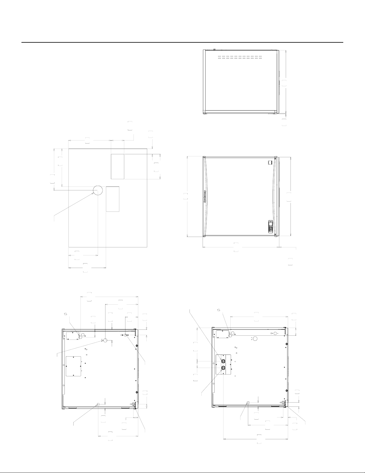
Cabinet Layout
76.2
30.00
73.8
29.06
78
30.70
0.3
.12
CHUTE
EXTENTION
4
1.59
4.7
1.85
62.6
24.64
32.3
12.71
6.4
2.50
.88
ELECTRICAL
CONNECTION
55.7
21.92
7.5
2.94
38.6
15.20
3.9
1.52
3/8" FLARE
MACHINE
WATER
INLET
3/4" FPT
MACHINE WATER
DRAIN
REMOTE COND.
LIQUID LINE
3/8" COPPER
BRAZE JOINT
REMOTE COND.
DISCHARGE LINE
1/2" COPPER
(REMOTE ONLY)
BRAZE JOINT
REMOTE LOW SIDE
SUCTION LINE
3/4" COPPER
(LOW SIDE ONLY)
BRAZE JOINT
33
13.00
10.2
4.00
TYP. (2)
4.2
1.65
19.3
7.60
TYP (2)
29.3
11.55
29.1
11.46
22.8
8.96
32.2
12.68
OPTIONAL BIN STAT
OR ULTRA SONIC
BIN LEVEL SENSOR
ICE DROP
OPENING
ICE DROP
OPENING
61
24.00
0.6
.23
12.4
4.88
31.8
12.52
5.3
2.09
10.4
4.09
4
1.59
4.7
1.85
55.8
21.95
7.5
2.94
.88
ELECTRICAL
CONNECTIONS
38.6
15.20
3.9
1.52
1/2" FPT
CONDENSER DRAIN
3/8" FPT
CONDENSER
WATER INLET
3/4" FPT
MACHINE WATER
DRAIN
3/8" FLARE
MACHINE
WATER
INLET
REMOTE
BACK VIEW
FRONT VIEW
RIGHT SIDE VIEW
PLAN VIEW
WATER COOLED
BACK VIEW
NH2030, NS2030, FS2330
A Series Water and Remote User Manual
November 2020
Page 5
Unpacking & Install Prep
Remove the carton from the skid. Check for hidden
freight damage, notify the carrier immediately if any is
found. Retain the carton for the carrier’s inspection.
The machine is not bolted to the skid. If strapped
remove the strap.
Place on Bin or Dispenser
If reusing an existing bin, be sure that the bin is
in good shape and that the gasket tape on the
top is not torn up. Water leaks, not covered by
warranty, could result from a poor sealing surface. If
installing a remote or a remote low side, a new bin
is recommended due to the high cost to the user of
replacing an old bin when a remote system is on top.
Install the correct adapter, following the directions
supplied with that adapter.
Hoist the machine onto the adapter.
Note: The machine is heavy! Use of a mechanical lift
is recommended.
Position the machine on the bin or adapter. Secure
with straps from the hardware bag packed with the
machine, or those supplied with the adapter.
Remove any plastic covering the stainless steel
panels.
Remove any packaging, such as tape or foam blocks,
that may be near the gear reducer or ice chute.
Level the bin and ice machine front to back and left to
right by using the bin leg levelers.
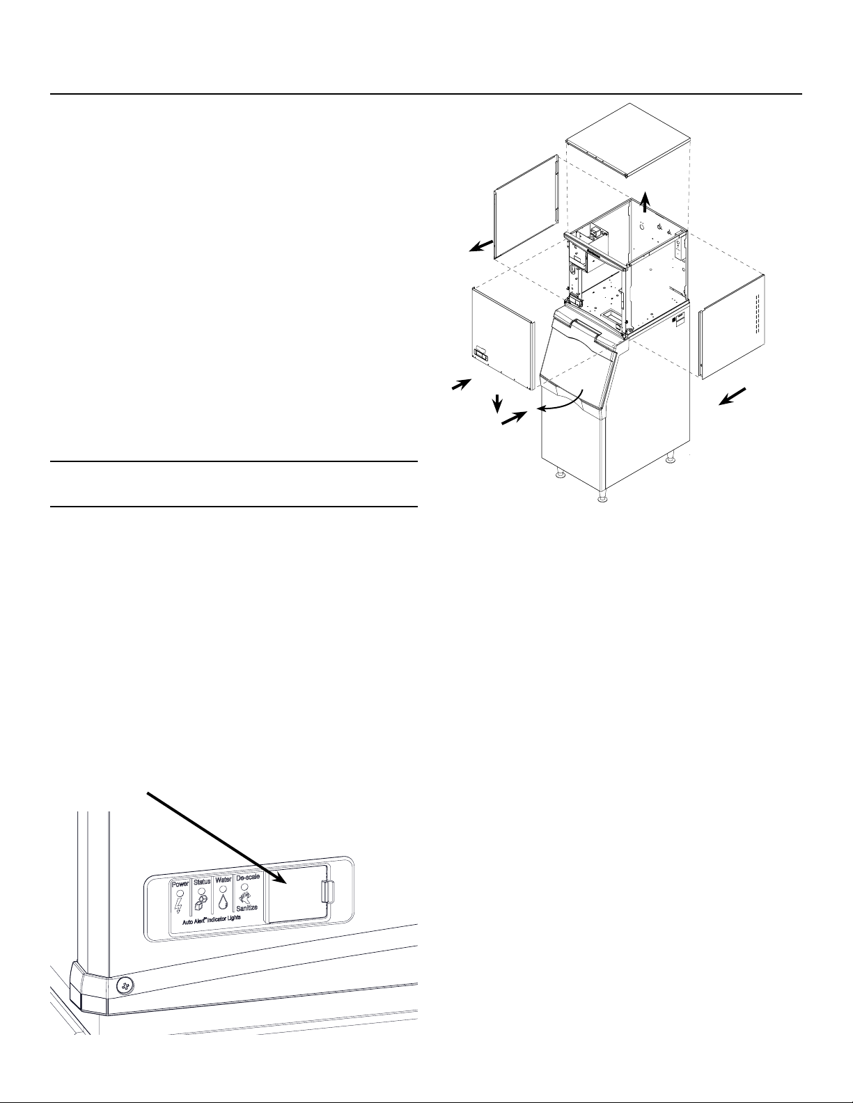
Control Panel Door
The door can be moved to allow access to the on and
o switches.
Panel Removal
1. Locate and loosen the two screws at the bottom of
the front panel.
2. Pull the front panel out at the bottom until it clears.
3. Lower the front panel down and o the machine.
4. Remove two screws at the front of the top panel.
Lift up the front of the top panel, push the top panel
back an inch, then lift to remove.
5. Locate and loosen the screw holding each side
panel to the base. Left side panel also has a screw
holding it to the control box.
6. Pull the side panel forward to release it from the
back panel.
NH2030, NS2030, FS2330
A Series Water and Remote User Manual
November 2020
Page 6
Water - Remote or Water Cooled
Water Supply
The water supply for ice making must be cold, potable
water. There is a single 3/8” male are potable water
connection on the back panel. Water cooled models
also have a 3/8” FPT inlet connection for the water
cooled condenser. Chilled water can also be used for
this connection.
Backow
The design of the oat valve and reservoir prevents
potable water backow by means of a 1" air gap
between the reservoir's maximum water level and the
oat valve water inlet orice.
Drain
There is one 3/4” FPT condensate drain tting at the
back of the cabinet. Water cooled models also have
a 1/2” FPT discharge drain connection on the back
panel.
Attach Tubing
Connect the potable water supply to the potable water
tting, 3/8” OD copper tubing or the equivalent is
recommended.
Water ltration is recommended. If there is an existing
lter, change the cartridge.
Connect the water cooled water supply to the
condenser inlet.
Note: Do NOT lter water to the water cooled
condenser circuit.
Drains - use rigid tubing: Connect the drain tube to the
condensate drain tting. Vent the drain.
Connect the water cooled condenser drain tube to the
condenser outlet. Do not vent this drain.
Do not tee ice machine drains into the drain tube
from the ice storage bin or dispenser. Back-ups
could contaminate and / or melt the ice in the bin or
dispenser. Be sure to vent the bin drain.
Follow all local and national codes for tubing, traps
and air gaps.
Water Inlet
Connection
Drain
Connection
Condensate
Drain Tube
Building Drain
Water Inlet
Connection
Drain
Connection
Condensate
Drain Tube
Condenser Inlet
Connection
Condenser
Drain Tube
Air Cooled or Remote Plumbing
Water Cooled Plumbing
NH2030, NS2030, FS2330
A Series Water and Remote User Manual
November 2020
Page 7
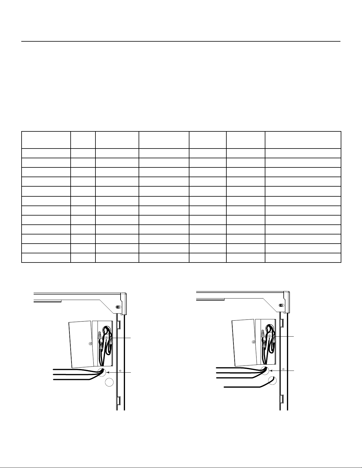
Electrical
The machine does not include a power cord, one
must be eld supplied or the machine hard wired to
the electrical power supply.
The junction box for the power cord is on the back
panel. See below.
Refer to the dataplate on the machine for minimum
circuit ampacity and determine the proper wire size
for the application. The dataplate (on the back of the
cabinet) also includes the maximum fuse size.
Connect electrical power to wires inside the junction
box in the back of the cabinet. Use a strain relief and
connect a ground wire to the ground screw.
Remote models power the condenser fan motor from
marked leads in the junction box.
Do not use an extension cord. Follow all local and
national codes.
Model Series Dimensions
w” x d” x h”
Voltage
Volts/Hz/Phase
Condenser
Type
Min Circuit
Ampacity
Max Fuse Size or HACR
Type Circuit Breaker
NS2030W-32 A 30 x 24 x 29 208-230/60/1 Water 22.2 30
NH2030W-32 A 30 x 24 x 29 208-230/60/1 Water 22.2 30
FS2330W-32 A 30 x 24 x 29 208-230/60/1 Water 22.2 30
NS2030W-3 A 30 x 24 x 29 208-230/60/3 Water 13.2 15
NH2030W-3 A 30 x 24 x 29 208-230/60/3 Water 13.2 15
FS2330W-3 A 30 x 24 x 29 208-230/60/3 Water 13.2 15
NS2030R-32 A 30 x 24 x 29 208-230/60/1 Remote 25.2 30
NH2030R-32 A 30 x 24 x 29 208-230/60/1 Remote 25.2 30
FS2330R-32 A 30 x 24 x 29 208-230/60/1 Remote 25.2 30
NS2030R-3 A 30 x 24 x 29 208-230/60/3 Remote 15.2 20
NH2030R-3 A 30 x 24 x 29 208-230/60/3 Remote 15.2 20
FS2330R-3 A 30 x 24 x 29 208-230/60/3 Remote 15.2 20
To Remote
Condenser
Fan Motor
Blue
Ground Wire
Connection
Black
White
Ground
Power
Supply
Wires
Install
Strain
Relief
Junction
Box
Cover
Ground Wire
Connection
Black
White
Ground
Power
Supply
Wires
Install
Strain
Relief
Junction
Box
Cover
Water Cooled Electrical Remote Electrical
NH2030, NS2030, FS2330
A Series Water and Remote User Manual
November 2020
Page 8
Remote condenser models have additional installation
needs.
The correct remote condenser fan and coil must
be connected to the ice making head. Liquid and
discharge tubing connections are on the back of
the ice machine cabinet. Tubing kits are available in
several lengths to accommodate most installations.
Order the one that just exceeds the length needed for
the installation.
The kit numbers are:
BRTE10, BRTE25, BRTE40, BRTE75
There are limits as to how far away from the ice
machine and where the remote condenser can be
located. See page 9 for those limits.
The correct condenser must be used:
Ice Machine
Model
Voltage Condenser
Model
NH2030R-32
NS2030R-32
FS2330R-32
NH2030R-3
NS2030R-3
FS2330R-3
208-230 ER6111-32
Do not reuse condenser coils contaminated with
mineral oil (used with R-502 for example). They will
cause compressor failure and will void the warranty.
A headmaster is required for all remote condenser
systems. Installation of headmaster kit KPFHM will be
required if any of the following condensers are being
used:
ERC101-1, ERC151-32, ERC201-32, ERC301-32,
ERC402-32
Use of non-Scotsman condensers requires
pre-approval from Scotsman Engineering.
Refrigeration - Remote Condenser Models
NH2030, NS2030, FS2330
A Series Water and Remote User Manual
November 2020
Page 9
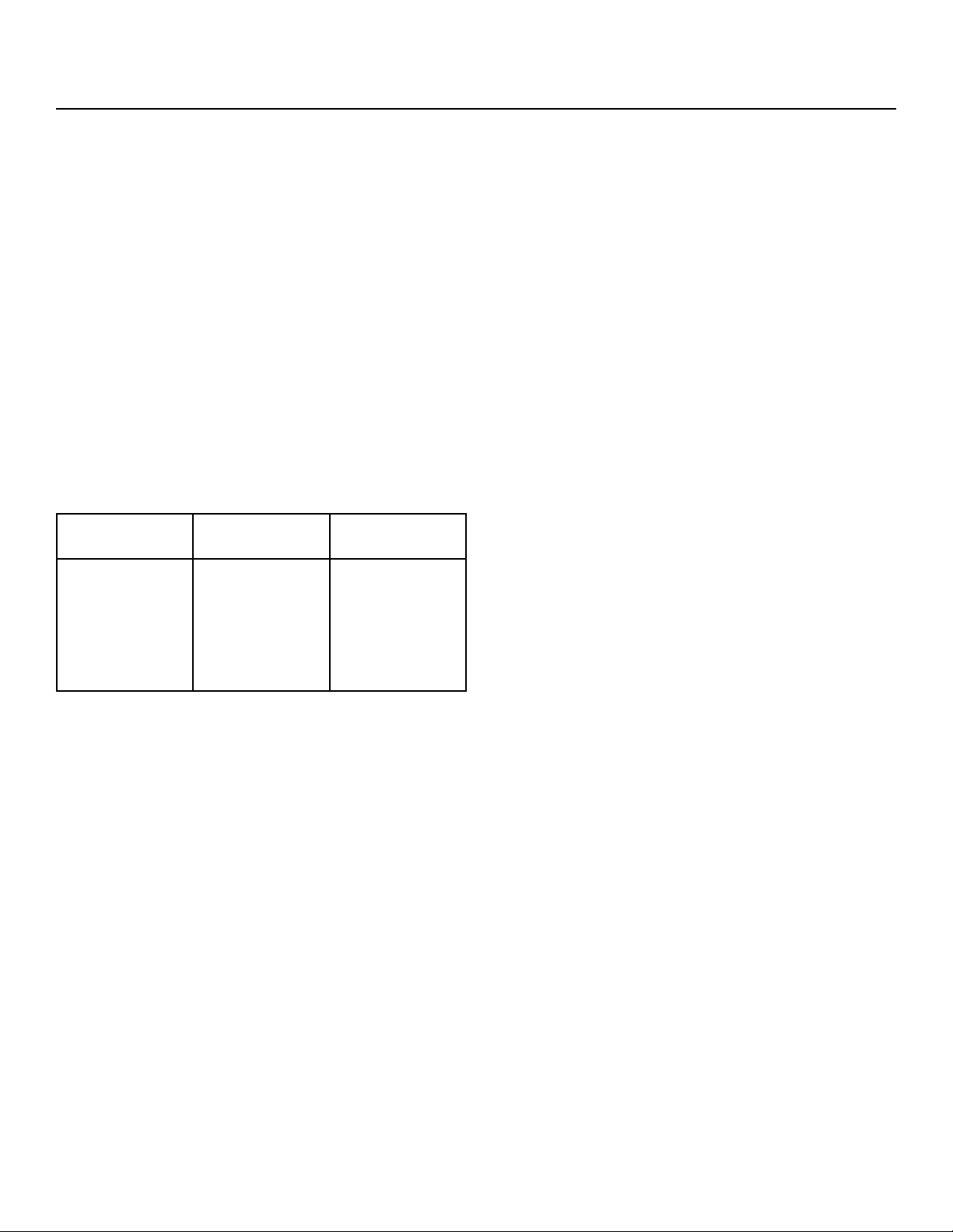
Remote Condenser Location - Limits
Use the following for planning the placement of the
condenser relative to the ice machine
Location Limits - condenser location must not exceed
ANY of the following limits:
• Maximum rise from the ice machine to the
condenser is 35 physical feet
• Maximum drop from the ice machine to the
condenser is 15 physical feet
• Physical line set maximum length is 100 feet.
• Calculated line set length maximum is 150.
Calculation Formula:
• Drop = dd x 6.6 (dd = distance in feet)
• Rise = rd x 1.7 (rd = distance in feet)
• Horizontal Run = hd x 1 (hd = distance in feet)
• Calculation: Drop(s) + Rise(s) + Horizontal
• Run = dd+rd+hd = Calculated Line Length
Congurations that do NOT meet these requirements
must receive prior written authorization from
Scotsman to maintain warranty.
Do NOT:
• Route a line set that rises, then falls, then rises.
• Route a line set that falls, then rises, then falls.
Calculation Example 1:
The condenser is to be located 5 feet below the ice
machine and then 20 feet away horizontally.
5 feet x 6.6 = 33. 33 + 20 = 53. This location would be
acceptable
Calculation Example 2:
The condenser is to be located 35 feet above and
then 100 feet away horizontally. 35 x 1.7 = 59.5.
59.5 +100 = 159.5. 159.5 is greater than the 150
maximum and is NOT acceptable.
Operating a machine with an unacceptable
conguration is misuse and will void the warranty.
22.87"
17.15"
40.35"
rd Max 35 feet
dd Max 15 feet
hd
Remote Condenser located
above ice machine.
Remote Condenser located
below ice machine.
Condenser Distance &
Location Schematic
NH2030, NS2030, FS2330
A Series Water and Remote User Manual
November 2020
Page 10
For The Installer: Remote Condenser
Locate the condenser as near as possible to the
interior location of the ice machine. Allow it plenty of
space for air and cleaning: keep it a minimum of two
feet away from a wall or other rooftop unit.
Note: The location of the condenser relative to the ice
machine is LIMITED by the specication on the prior
page.
Roof penetration
In many cases a roong contractor will need to make
and seal the hole in the roof for the line sets. The
suggested hole diameter is 2 inches.
Meet all applicable building codes.
Roof Attachment
Install and attach the remote condenser to the roof
of the building, using the methods and practices of
construction that conform to the local building codes,
including having a roong contractor secure the
condenser to the roof
Power Supply from
Ice Machine
To Remote Condenser
Refrigeration
connections
Brazing required
Refrigeration
Tubing
Remote Condenser
*reference page 4 for more detailed layout of rear panel connections
NH2030, NS2030, FS2330
A Series Water and Remote User Manual
November 2020
Page 11
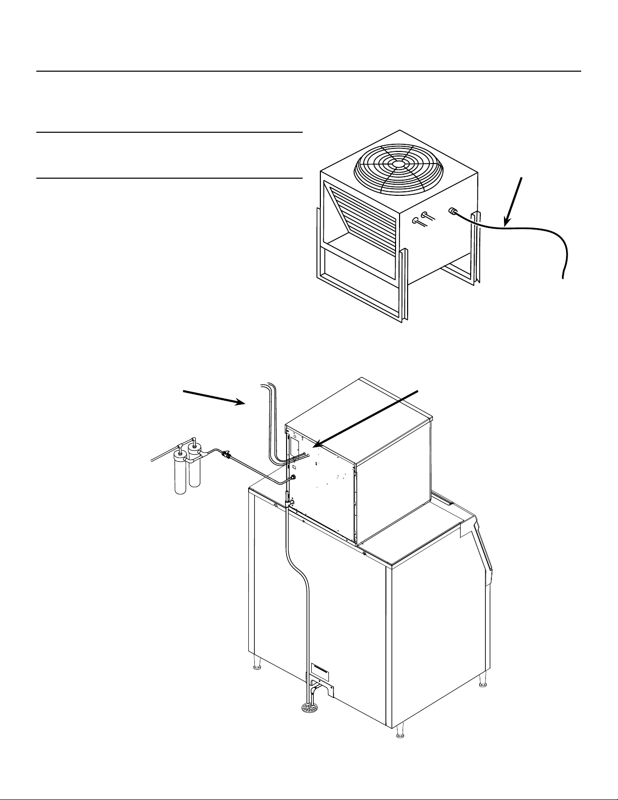
Line Set Routing and Brazing
Do not connect the refrigeration tubing until all routing
and forming of the tubing is complete. See the
Coupling Instructions for nal connections.
1. Each set of tubing lines contains a 3/8” diameter
liquid line, and a 1/2” diameter discharge line.
Both ends of each line are designed for eld
brazed connections.
Note: The openings in the building ceiling or wall,
listed in the next step, are the minimum sizes
recommended for passing the refrigerant lines
through.
2. Have a roong contractor cut a minimum hole for
the refrigerant lines of 2”. Check local codes, a
separate hole may be required for the electrical
power supply to the condenser.
Caution: Do NOT kink the refrigerant tubing while
routing it.
3. Route the refrigerant tubes through the roof
opening. Follow straight line routing whenever
possible. Excess tubing must be cut to proper
length prior to connecting to the ice maker and
condenser.
4. The tubing must be evacuated after connection
to the ice maker or condenser before opening the
ball valve.
5. Have a roong contractor seal the holes in the
roof per local codes
To Remote
Condenser
Fan Motor
Power Supply to Condenser
Refrigeration Tubing
Potable Water
Supply
Condensate Drain
*reference page 4 for more detailed layout of rear panel connections

NH2030, NS2030, FS2330
A Series Water and Remote User Manual
November 2020
Page 12
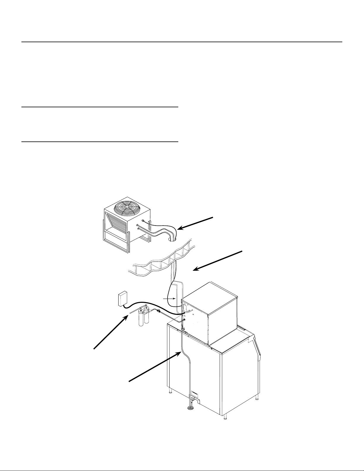
Line Set Routing and Brazing
Do not connect the refrigerant tubing until all
routing and forming of the tubing is complete.
Final connections requires brazing, steps must
be performed by an EPA certied type II or higher
technician.
The Lineset of tubing contains a 3/8” diameter liquid
line, and a 1/2” diameter discharge line.
Note: The openings in the building ceiling or wall,
listed in the next step, are the minimum sizes
recommended for passing the refrigerant lines
through.
Have the roong contractor cut a minimum hole for
the refrigerant lines of 1 3/4”. Check local codes,
a separate hole may be required for the electrical
power supply to the condenser.
Caution: Do NOT kink the refrigerant tubing while
routing it.
At Condenser
1. Remove protective plugs from both connections
and vent the nitrogen from the condenser.
2. Remove the tubing access bracket to allow more
room for brazing.
3. Route the lineset tubes to there connection.
4. Clean tubing ends and position into stubs.
Note: Be sure tube and stubs are round, dress with
swage tool if needed.
At Head
1. Remove the tubing access bracket to allow
more room for brazing.
2. Conrm connection ball valves are fully
closed.
3. Remove protective plugs from both connec-
tions.
4. Remove caps from access valve connec-
tions.
5. Remove cores from access valves.
6. Connect refrigeration hoses to access
valves.
7. Connect dry nitrogen source to liquid line
connection.
8. Shorten tubing to correct length, clean ends
and insert them into valve stubs.
Note: Be sure tube and stubs are round, dress with
swage tool if needed.
9. Add heat sink material to ball valve body.
10. Open nitrogen and ow 1 psi nitrogen into
liquid line tube and braze the liquid line and
suction line tubes to the valve stubs.
11. With nitrogen owing braze the liquid and
suction line connections.
At Condenser
1. Braze the liquid and suction line connections.
At Head
1. Remove nitrogen source.
2. Return valve cores to access valves.
3. Connect vacuum pump to both access
valves and evacuate the tubing and head to
at least a 300 micron level.
4. Remove vacuum pump and add R-404A to
all three tubes to provide a positive pressure.
5. Leak check the all braze connections and
repair any leaks.
6. Open both valves to full open.
Note: The full refrigerant charge is contained in the
receiver of the ice machine.
NH2030, NS2030, FS2330
A Series Water and Remote User Manual
November 2020
Page 13
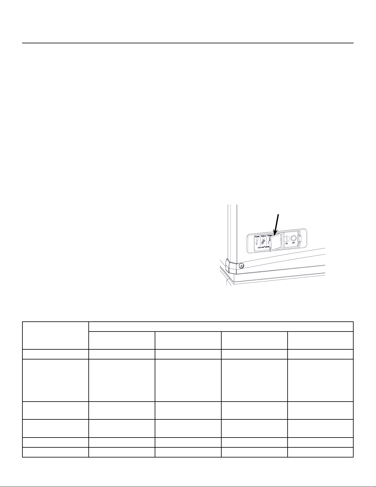
Power
Status
No Water
Time to Clean
On
O
Final Check List
After connections
1. Wash out the bin. If desired, the interior of the bin
could be sanitized.
2. Locate the ice scoop (if supplied) and have it
available for use when needed.
3. Remote only: Switch on the electrical power to
warm up the compressor. Do not start the machine
for 4 hours.
Final Check List
1. Is the unit located indoors in a controlled
environment?
2. Is the unit located where it can receive adequate
cooling air?
3. Has the correct electrical power been supplied to
the machine?
4. Have all the water supply connections been
made?
5. Have all the drain connections been made?
6. Has the unit been leveled?
7. Have all unpacking materials and tape been
removed?
8. Has the protective covering on the exterior panels
been removed?
9. Is the water pressure adequate?
10. Have the drain connections been checked for
leaks?
11. Has the bin interior been wiped clean or sanitized?
12. Have any water lter cartridges been replaced?
13. Have all required kits and adapters been properly
installed?
Control and Machine Operation
Once started, the ice machine will automatically make
ice until the bin or dispenser is full of ice. When ice
level drops, the ice machine will resume making ice.
Caution: Do not place anything on top of the ice
machine, including the ice scoop. Debris and moisture
from objects on top of the machine can work their way
into the cabinet and cause serious damage. Damage
caused by foreign material is not covered by warranty.
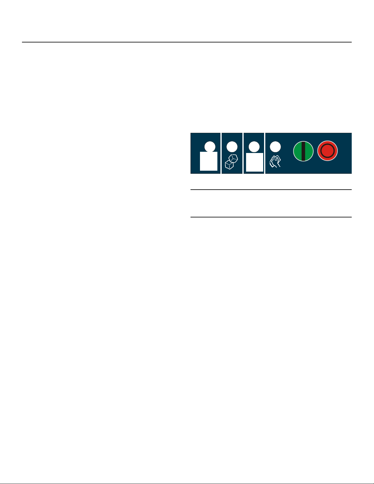
There are four indicator lights at the front of the
machine that provide information on the condition
of the machine: Power, Status, Water, De-scale &
Sanitize.
Note: If the De-Scale & Sanitize light is ON, following
the cleaning process will clear the light for another
cleaning time internal.
Two button switches are at the front – On and O. To
switch the machine OFF, push and release the O
button. The machine will shut o at the end of the next
cycle. To switch the machine ON, push and release
the On button. The machine will go through a start up
process and then resume ice making.
Lower Light and Switch Panel
This user accessible panel provides important
operational information and duplicates the lights and
switches on the controller. It also allows access to the
On and O buttons that operate the ice machine.
Sometimes access to the switches should be limited
to prevent unauthorized operation. For that purpose a
xed panel is shipped in the hardware package. The
xed panel cannot be opened.
To install the xed panel
1. Remove the front panel and remove the bezel.
2. Spread the bezel frame open and remove original
door, insert xed panel into bezel. Be sure it is in
the closed position.
3. Return bezel to panel and install panel on unit.

NH2030, NS2030, FS2330
A Series Water and Remote User Manual
November 2020
Page 14
Initial Start Up and Maintenance
Startup
1. Turn the water supply on. Remote models also
open the liquid line valve.
2. Conrm voltage and switch on electrical power.
3. Push and release the On button. The machine will
start in about two minutes.
4. Soon after starting, air cooled models will begin
to blow warm air out the back of the cabinet and
water cooled models will drain warm water from
the condenser drain tube. Remote models will be
discharging warm air from the remote condenser.
After about 5 minutes, ice will begin to drop into
the bin or dispenser.
5. Check the machine for unusual rattles. Tighten
any loose screws, be sure no wires are rubbing
moving parts. Check for tubes that rub. Remote
models check brazed connections for leaks,
retighten as needed.
6. Scan the QR code found behind the front panel
door and complete the warranty registration
online or ll out and mail the included warranty
registration card
7. Notify the user of the maintenance requirements
and whom to call for service.
Maintenance Types
This ice machine needs ve types of maintenance:
• Remote models need their condenser coils
cleaned regularly.
• All models need scale removed from the water
system.
• All models require regular sanitization.
• All models require sensor cleaning.
• All models require a top bearing check.
Maintenance Frequency
Remote air cooled condenser: At least twice a year, or
every time the unit is cleaned
Scale removal. At least twice a year, in some water
conditions it might be every 3 months. The yellow De-
Scale & Sanitize light will switch on after a set period
of time as a reminder. The default time period is 6
months of power up time.
Sanitizing: Every time the scale is removed or as
often as needed to maintain a sanitary unit.
Sensor Cleaning: Every time the scale is removed.
Top bearing check: At least twice a year or every
time the scale is removed. During the course of
normal operation, some material buildup on top of the
bearing is normal and should be wiped away during
maintenance.
Maintenance Specics
Maintenance: Remote air cooled condenser
The condenser ns will occasionally need to be
cleaned of leaves, grease or other dirt. Check the coil
every time the ice machine is cleaned.
Maintenance: Exterior Panels
The front and side panels are durable stainless steel.
Fingerprints, dust and grease will require cleaning
with a good quality stainless steel cleaner
Note: If using a sanitizer or a cleaner that contains
chlorine on the panels, after use be sure to wash the
panels with clean water to remove chlorine residue.
Maintenance: Water lters
If the machine has been connected to water lters,
check the cartridges for the date they were replaced
or for the pressure on the gauge. Change cartridges
if they’ve been installed more than 6 months or if the
pressure drops too much during ice making.
NH2030, NS2030, FS2330
A Series Water and Remote User Manual
November 2020
Page 15
Maintenance: Scale Removal and Sanitation
Note: Following this procedure will reset the de-scale
and sanitize light.
Preparing to clean
1. Remove both the front and right panels.
2. Push and release the OFF button.
3. Remove ice from bin or dispenser.
4. Turn the water supply to the oat valve OFF by
turning the knob 1/4 turn CCW.
5. Drain the water reservoir into a bucket using the
vent tube.
6. Drain the evaporators by disconnecting the
evaporator water supply tube from the water
reservoir. Take the evaporator water supply tube
o the tube support bracket on the front right post
and lower to fully empty both evaporators. (see
diagram below)
7. Put the evaporator water supply tube back
on top of the tube support bracket, reconnect
the evaporator water supply tube to the water
reservoir, and return the vent tube to it’s original
collar bracket.
8. Loosen the thumb screw and raise the water
reservoir from the “make ice” position to the
“clean” position.
9. Remove the water reservoir cover.
10. Remove both ice chute covers.
Scale Removal
11. Prepare a solution of 32oz. Scotsman Clear One
scale remover and 32oz. 95-115 °F. potable water.
12. Using a small cup for precise pouring, add the
scale remover solution into the reservoir until the
solution comes out of top of the evaporators at the
extruders, about 2qts.
13. Push and release the Clean button: C is displayed
and the Time to Clean light blinks. The augers
will turn and circulate the scale remover for 30
minutes before shutting o. No ice is made during
the cleaning cycle.
14. Drain the water reservoir and evaporators by
repeating steps 5-7.
Sanitize
15. Prepare a solution of sanitizer. Mix 4 oz. of
NuCalgon IMS and 2.5 gallons of 95-115 °F.
potable water to create a 200 ppm solution.
16. Using a small cup for precise pouring, add the
sanitizer solution into the reservoir until the
solution comes out of top of the evaporators at
the extruders, about 2qts. Reserve any exess
sanitizer.
17. Allow the sanitizer to soak while steps 18-22 on
the following page are completed, or at least 60
seconds.
Ice machine scale remover
contains acids. Acids can
cause burns.
If concentrated cleaner
comes in contact with
skin, ush with water. if
swallowed, do NOT induce
vomiting.
Give large amounts of
water or milk. Call Physician
immediately. Keep out of the
reach of children.
CLEAN
MAKE
ICE
Vent Tube
Water Supply Knob
Evaporator Water
Supply Tube
Tube Support Bracket
Thumb Screw
Water Reservoir
NH2030, NS2030, FS2330
A Series Water and Remote User Manual
November 2020
Page 16
Maintenance: Scale Removal and Sanitation Continued
Remove internal parts for cleaning
18. Remove the water sensor, ice sweeps(2), upper
ice chute(2), bin eyes(2 sets), and lower ice
chutes(2) for additional cleaning. The reservoir
cover and chute covers(2) were already removed
and should also be cleaned.
19. Prepare a solution of 4oz. Scotsman Clear One
scale remover and 16oz. 95-115 °F. potable water.
Using a nylon brush, scrub each part with scale
remover and rinse, excluding the bin eyes.
20. Using the remaining sanitizing solution and a
nylon brush, scrub each part, exlcluding the bin
eyes.
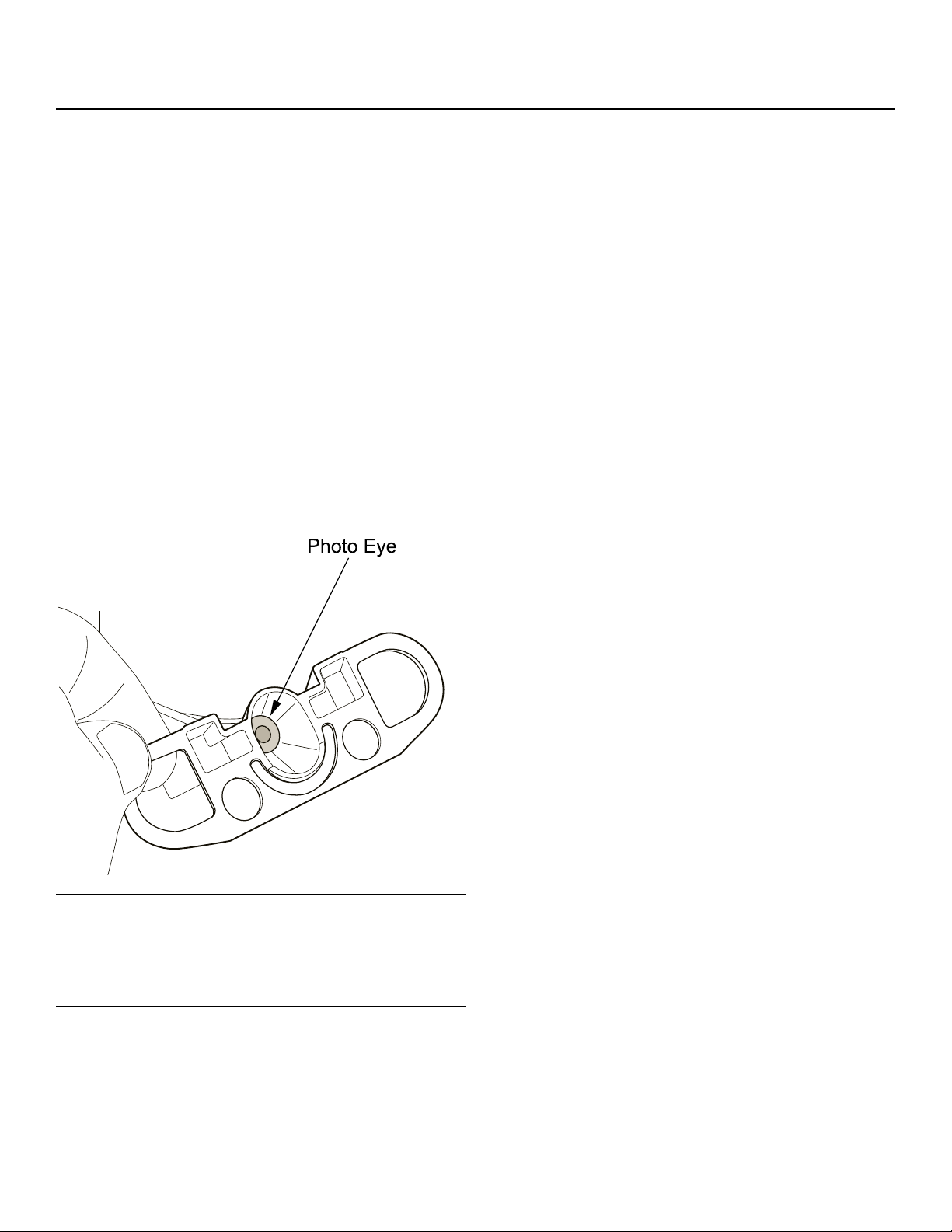
21. Gently wipe down the bin eyes with scale remover,
rinse, and dry thoroughly (see detail below).
22. Return all parts to their original position.
Finish Cleaning Process
23. Drain the water reservoir and evaporators by
repeating steps 5-7 (previous page).
24. Loosen the thumb screw and lower the water
reservoir from the “clean” position back to the
“make ice” position.
25. Wash the inside of the ice storage bin with
sanitizing solution.
26. Switch the water supply to the ice machine ON
and check for leaks as the system lls.
27. Push and release the ON button.
28. Return the right and front panels to their original
position and secure with the original screws.
Change De-Scale Notication Interval
This feature is accessible only from standby (Status
Light O).
1. Press and hold Clean button for 3 seconds.
This starts the Time to Clean Adjustment State and
displays the current time to clean setting.
2. Press the clean button repeatedly to cycle through
the 4 possible settings:
0 (disabled), 4 months, 6 months (default), 1 year
3. Push O to conrm the selection.
Note: Eye holders must be thoroughly dried and
mounted properly. They snap into a centered position
and are properly located when the wires are routed to
the back and the left eye is the one with 2 wires at the
connector.
NH2030, NS2030, FS2330
A Series Water and Remote User Manual
November 2020
Page 17
Options
Vari-Smart
Optional adjustable ice level control (KVS). When
this option is present there is an adjustment post and
an additional indicator light to the right of the four
indicator lights mentioned earlier.
The ultrasonic ice level control allows the user to
control the point that the ice machine will stop making
ice before the bin or dispenser is full.
Reasons for this include:
• Seasonal changes in ice used
• Planning to sanitize the bin
• Faster turnover for fresher ice
• Certain dispenser applications where maximum ice
level is not desired
Use of Adjustable Ice Level Control
There are several positions the ice level can be set to,
including O or Max (knob and label indicators lined
up), where it lls the bin until the standard bin control
shuts the machine o. See the kit’s instructions for
complete details including special instructions for
dispenser applications.
Rotate the adjustment post to the desired ice level.
The machine will ll up to that level and when it shuts
o the indicator light next to the adjustment post will
be On.
Note: The maximum ll position is when the arrow on
the knob points to the arrow on the label.
NH2030, NS2030, FS2330
A Series Water and Remote User Manual
November 2020
Page 18
What to Do Before Calling for Service
Normal Operation
Ice:
The machine will make either aked or nugget ice,
depending upon the model. The ice will be produced
continuously until the bin is full. It is normal for a few
drops of water to occasionally fall with the ice.
Heat:
On remote models most heat is exhausted at the
remote condenser, the ice machine should not
generate signicant heat. Water cooled models
also put most of the heat from ice making into the
discharge water.
Noise:
The ice machine will make noise when it is in ice
making mode. The compressor and gear reducer will
produce sound. Air cooled models will add fan noise.
Some ice making noise could also occur. These
noises are all normal for this machine.
Reasons the machine might shut itself o:
• Lack of water.
• Does not make ice
• Auger motor overload
• High discharge pressure.
• Low refrigeration system pressure.
Check the following
1. Has the water supply to the ice machine or
building been shut o? If yes, the ice machine will
automatically restart within minutes after water begins
to ow to it.
2. Has power been shut o to the ice machine? If yes,
the ice machine will automatically restart when power
is restored.
3. Has someone shut the power o to the remote
condenser while the ice machine still had power? If
yes, the ice machine may need to be manually reset.
To Manually Reset the machine.
• Open the switch door
• Push and release the O button.
• Push and release the On button.
To Shut the Machine O:
Push and hold the O button for 3 seconds or until the
machine stops.
Indicator Lights & Their Meanings
Power Status Water De-Scale &
Sanitize
Steady Green Normal Normal - -
Blinking Green Self Test Failure Switching on or
o. When Smart-
Board used,
machine attention
recommended.
- -
Blinking Red - Diagnostic shut
down
Lack of water -
Yellow - - - Time to descale and
sanitize
Blinking Yellow - - - In Cleaning Mode
Light O No power Switched to O Normal Normal
Open Switch Door

SCOTSMAN ICE SYSTEMS
101 Corporate Woods Parkway
Vernon Hills, IL 60061
800-726-8762
www.scotsman-ice.com
17-3719-01