HDCVI Mobile Camera
User’s Manual
V1.0.1
Foreword I
Foreword
General
This user’s manual (hereinafter referred to be "the Manual") introduces the functions,
installation and operations of the camera.
Safety Instructions
The following categorized signal words with defined meaning might appear in the Manual.
Signal Words
Meaning
Indicates a medium or low potential hazard which, if not avoided,
could result in slight or moderate injury.
Indicates a potential risk which, if not avoided, may result in
property damage, data loss, lower performance, or unpredictable
result.
Provides methods to help you solve a problem or save you time.
Provides additional information as the emphasis and supplement
to the text.
Revision History
No.
Version
Revision Content
Release Date
1
V1.0.0
First release.
2018.03
Privacy Protection Notice
As the device user or data controller, you might collect personal data of others' such as face,
fingerprints, car plate number, Email address, phone number, GPS and so on. You need to be
in compliance with the local privacy protection laws and regulations to protect the legitimate
rights and interests of other people by implementing measures include but not limited to:
providing clear and visible identification to inform data subject the existence of surveillance
area and providing related contact.
About the Manual
The Manual is for reference only. If there is inconsistency between the Manual and the
actual product, the actual product shall govern.
We are not liable for any loss caused by the operations that do not comply with the Manual.
The Manual would be updated according to the latest laws and regulations of related
regions. For detailed information, see the paper User's Manual, CD-ROM, QR code or our

Foreword II
official website. If there is inconsistency between paper User's Manual and the electronic
version, the electronic version shall prevail.
All the designs and software are subject to change without prior written notice. The product
updates might cause some differences between the actual product and the Manual. Please
contact the customer service for the latest program and supplementary documentation.
There still might be deviation in technical data, functions and operations description, or
errors in print. If there is any doubt or dispute, please refer to our final explanation.
Upgrade the reader software or try other mainstream reader software if the Guide (in PDF
format) cannot be opened.
All trademarks, registered trademarks and the company names in the Manual are the
properties of their respective owners.
Please visit our website, contact the supplier or customer service if there is any problem
occurred when using the device.
If there is any uncertainty or controversy, please refer to our final explanation.
Foreword I
Important Safeguards and Warnings
Electrical Safety
All installation and operation should conform to your local electrical safety codes.
The power source shall conform to the requirement of the Safety Extra Low Voltage (SELV)
standard, and supply power with rated voltage which conforms to Limited power Source
requirement according to IEC60950-1. Please note that the power supply requirement is
subject to the device label.
A readily accessible disconnect device shall be incorporated in the building installation
wiring.
Make sure if the camera power adapter meets the camera operating voltage requirement
before powering up the device (The material and length of the power cable might influence
the device voltage).
Prevent the power cable from being trampled or pressed, especially the plug, power socket
and the junction extruded from the device.
We assume no liability or responsibility for all the fires or electrical shock caused by
improper handling or installation.
Environment
Do not aim the device at strong light to focus, such as lamp light and sun light.
Transport, use and store the device within the range of allowed humidity and temperature.
Keep the camera away from water or other liquid to avoid damages to the internal
components.
Keep sound ventilation to avoid heat accumulation.
Heavy stress, violent vibration or water splash are not allowed during transportation,
storage and installation.
Pack the device with standard factory packaging or the equivalent material when
transporting the device.
It is recommended to use the device together with lightning arrester to improve lightning
protection effect.
It is recommended to get the grounding holes to be grounded to enhance the reliability of
the device.
It is recommended to use qualified video transmission cable to improve video quality. It is
recommended to use RG59 coaxial cable or higher standard.
Use standard components or accessories provided by manufacturer and make sure the

Foreword II
device is installed and maintained by professional engineers.
The surface of the image sensor should not be exposed to laser beam radiation in an
environment where a laser beam device is used.
Do not provide two or more power supply sources for the device; otherwise it might
damage the device.
When the camera is in the condition of PoC power supply, do not connect any other device
between the camera and PoC transceiver including UTC, Balun, optical transceiver,
distributor and convertor and so on; otherwise, the device might get burned.
PoC supply voltage is up to 52V. Do not dismantle the device during normal operation;
otherwise it might cause danger to both device and users due to high voltage.

Table of Contents III
Table of Contents
Foreword .................................................................................................................................................... I
1 Introduction ............................................................................................................................................ 1
1.1 General.......................................................................................................................................... 1
1.2 Features ........................................................................................................................................ 1
2 Design ..................................................................................................................................................... 2
2.1 Dimension ..................................................................................................................................... 2
2.2 Cable ............................................................................................................................................. 3
3 Installation .............................................................................................................................................. 5
3.1 Installing Model A Series ............................................................................................................... 5
3.2 Installing Model B .......................................................................................................................... 6
3.3 Installing Model C.......................................................................................................................... 7
3.4 Installing Model D (1) .................................................................................................................... 8
3.5 Installing Model D (2) and Model D (3) ......................................................................................... 8
4 Configuration ....................................................................................................................................... 10
4.1 Setting HCVR .............................................................................................................................. 10
4.2 Setting Audio Input ...................................................................................................................... 12
4.3 Operating OSD Menu ................................................................................................................. 12
5 Maintenance ......................................................................................................................................... 15

Introduction 1
1 Introduction
1.1 General
This series of products comply with the HDCVI standard and support the transmission of video
and control signal over coaxial cable. They produce video signal with megapixel resolution and
require HCVR device that comply with the HDCVI standard to achieve high speed, long
distance and zero lag transmission of the signal. They are applicable to cover the monitoring
needs for bus, school bus and subway.
1.2 Features
720p series support over 800 meter real-time transmission of video and control signal from
RG59 cable, for 1080p series, the distance is 500 meter.
Configuring devices easily with OSD menu.
Support switching between HD/SD outputs.
Design 2
2 Design
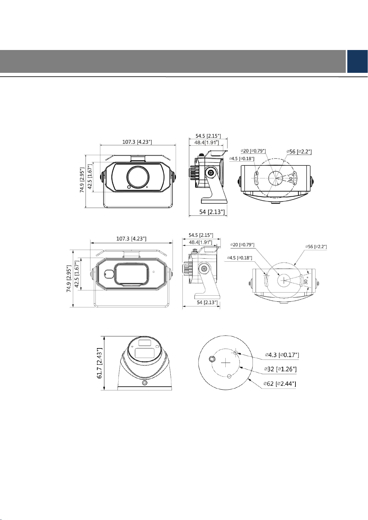
2.1 Dimension
Model A (1) (mm [in]) Figure 2-1
Model A (2) (mm [in]) Figure 2-2
Model B (mm [in]) Figure 2-3
Model C (mm [in]) Figure 2-4
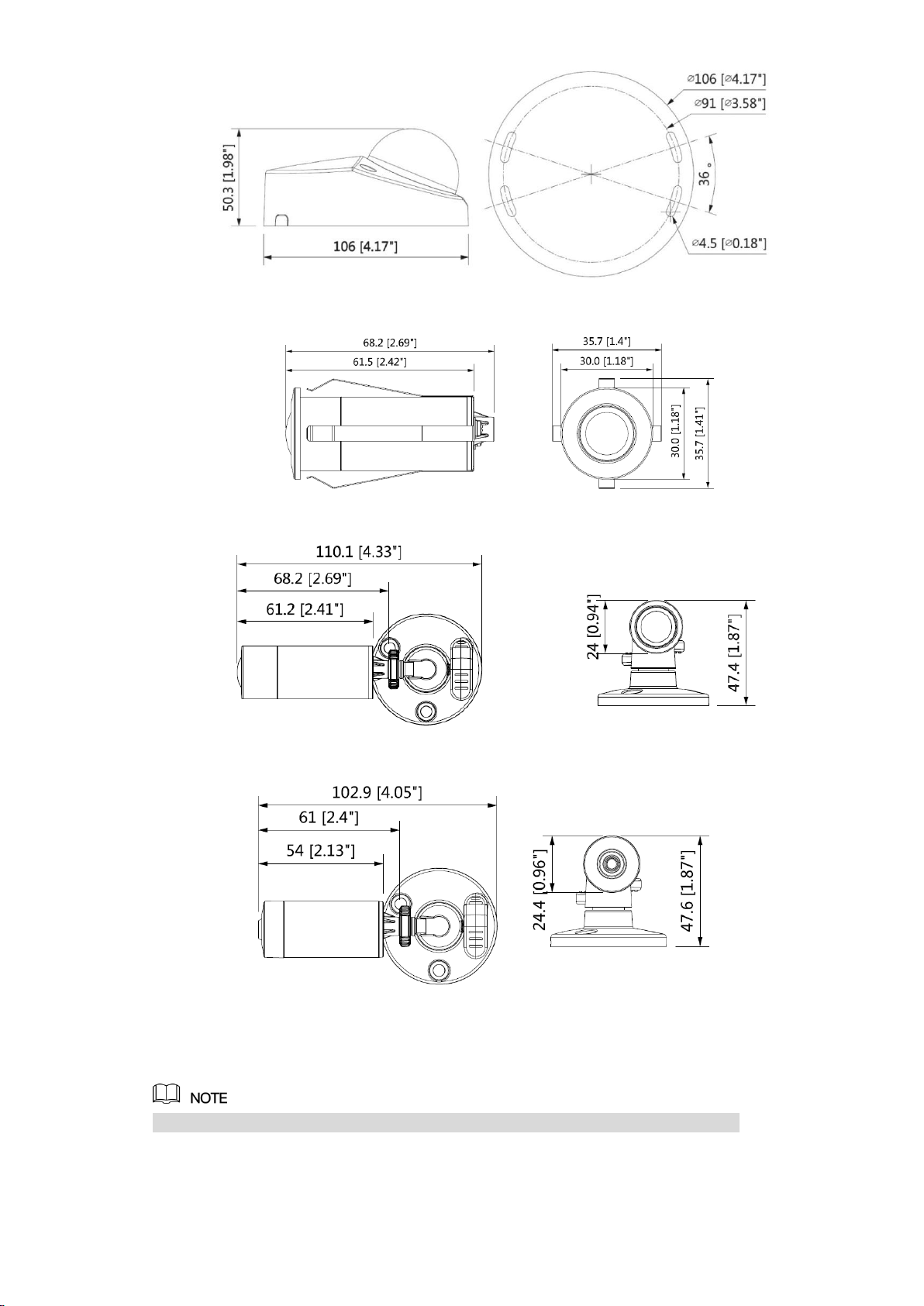
Design 3
Model D (1) (mm [in]) Figure 2-5
Model D (2) (mm [in]) Figure 2-6
Model D (3) (mm [in]) Figure 2-7
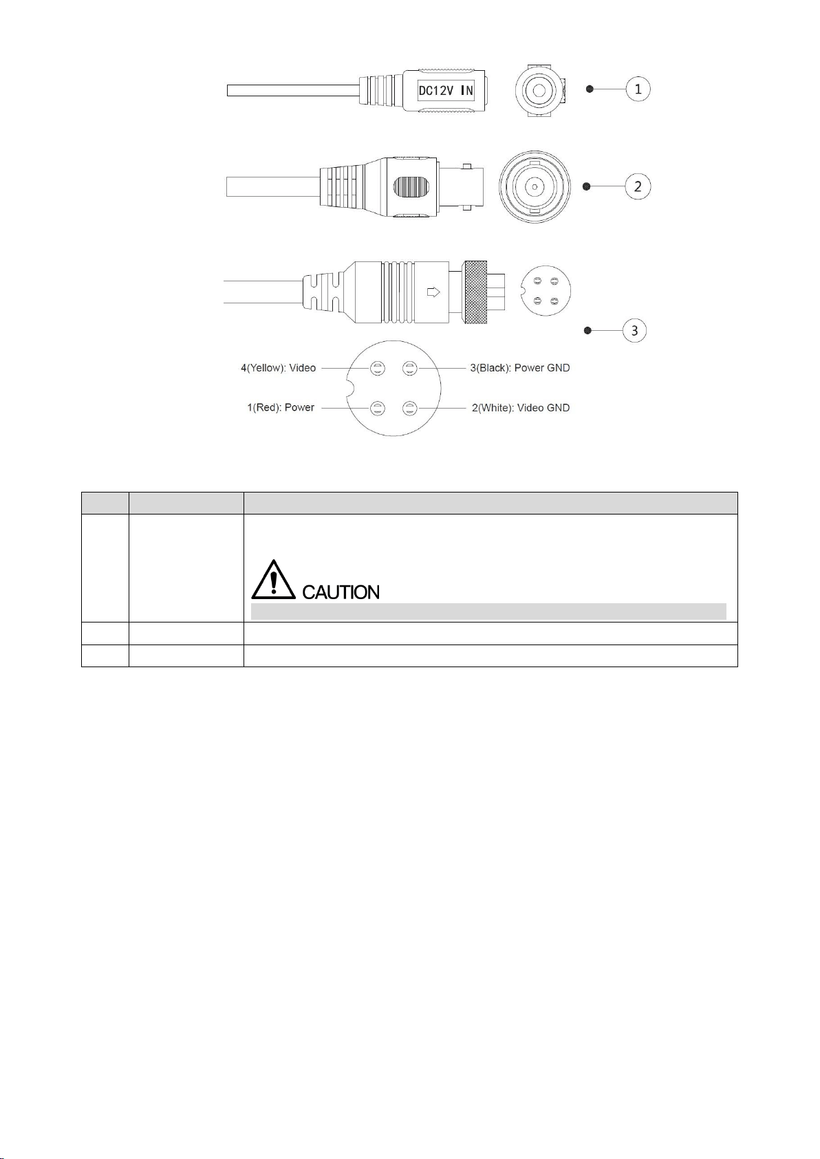
2.2 Cable
Cable type might vary with different cameras, and the actual product shall prevail.
DC 12V Power Input Figure 2-8
Design 4
Video Output Figure 2-9
Aviation Port Figure 2-10
For more information about cable ports, see Table 2-1.
Table 2-1 Cable information
No.
Port Name
Function
①
DC 12V Power
Input
Inputs DC 12V power. Please be sure to supply power as instructed in the
Manual.
Device abnormity or damage could occur if power is not supplied correctly.
②
Video Output
Connects to HCVR to output video signal.
③
Aviation Port
Connects to HCVR to output video signal.
Installation 5
3 Installation
Make sure the mounting surface is strong enough to hold at least three times of the
camera weight.
Keep the protection film on the dome before installation and adjustment finished to avoid
possible scratch.
Properly handle the device after unpacking. Do not expose the device in humid
environment.
The following figure is for reference only, and the actual product shall prevail.
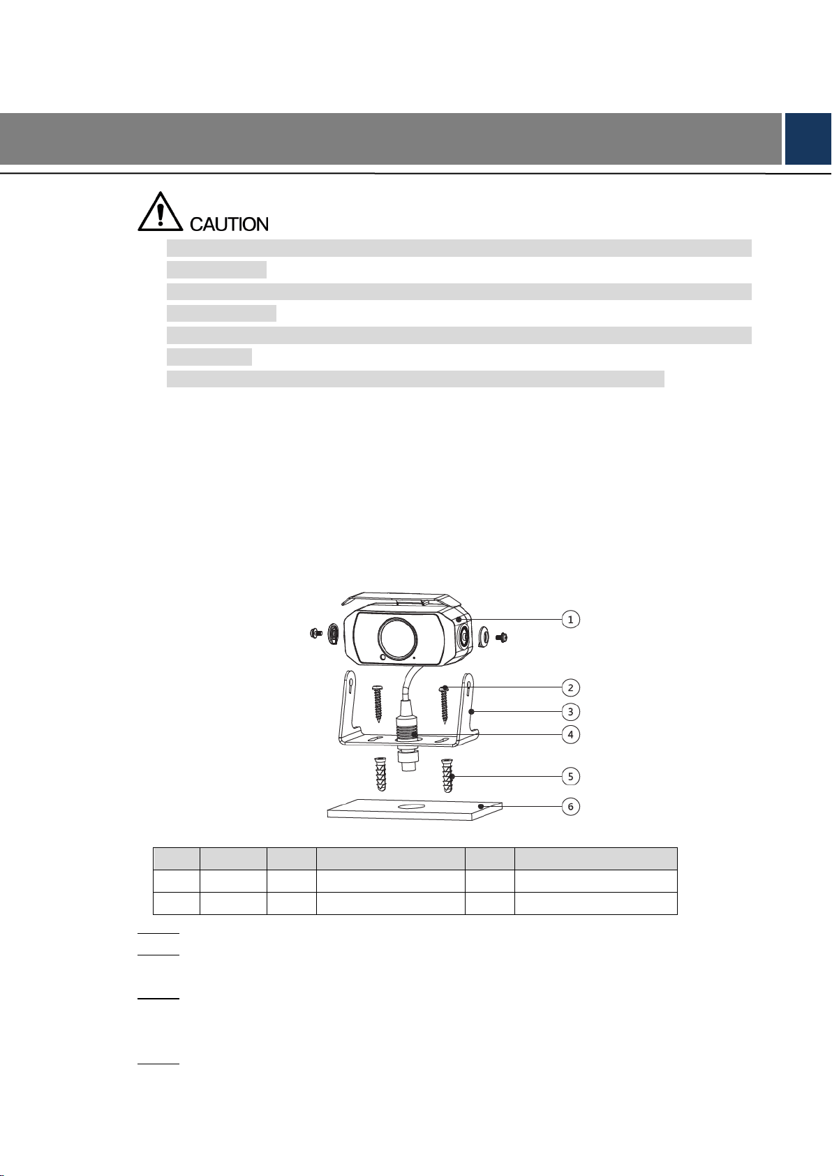
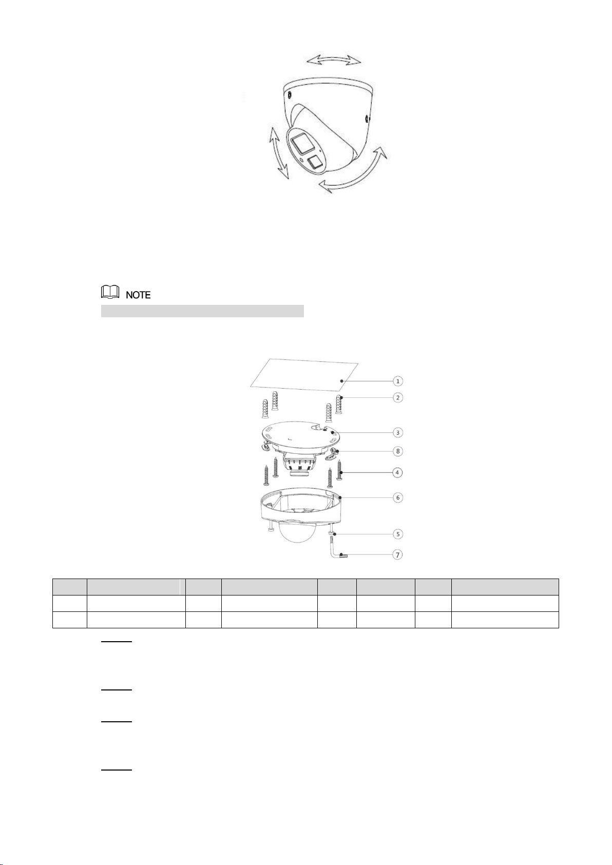
3.1 Installing Model A Series
For the installation diagram and item list of model A (1) and model A (2), see Figure 3-1 and
Table 3-1.
Model A series installation diagram Figure 3-1
Table 3-1 Model A series installation item list
No.
Item
No.
Item
No.
Item
①
Device
②
Self-tapping screw
③
Bracket
④
Cable
⑤
Expansion bolt
⑥
Mounting surface
Unscrew the locking screws on the bracket③ to detach it. Step 1
Drill screw holes (and the cable outlet hole if it needs to go through the mounting Step 2
surface) on the mounting surface⑥, then insert expansion bolts⑤ in the screw holes.
Align the screw holes on the bracket③ to those on the mounting surface⑥, then put in Step 3
and fasten the supplied self-tapping screws② to attach the bracket③ to the mounting
surface.
Adjust the location of the device① on the bracket③ and fasten the locking screws to Step 4
attach the device① on the bracket③.
Installation 6
3.2 Installing Model B
For the installation diagram and item list of model B, see Figure 3-2 and Table 3-2.
Model B installation diagram Figure 3-2
Table 3-2 Model B installation item list
No.
Item
No.
Item
No.
Item
No.
Item
①
Mounting surface
②
Expansion bolt
③
Pedestal
④
Self-tapping screw
⑤
Device
⑥
Enclosure
⑦/⑧
Locking screw
—
—
Drill screw holes (and the cable outlet hole if it needs to go through the mounting Step 1
surface) on the mounting surface① as indicated on the positioning map, then insert
expansion bolts② in the screw holes.
Loosen the locking screws⑦/⑧ and take the pedestal③ off. Step 2
Adjust the location of the pedestal③ according to cable outlet requirement (top out or Step 3
side out), then pull the cable out through the mounting surface① or the side cable tray.
Align the screw holes on the pedestal③ to those on the mounting surface, then put in
and fasten the self-tapping screws④ to attach the device⑤ to the mounting surface.
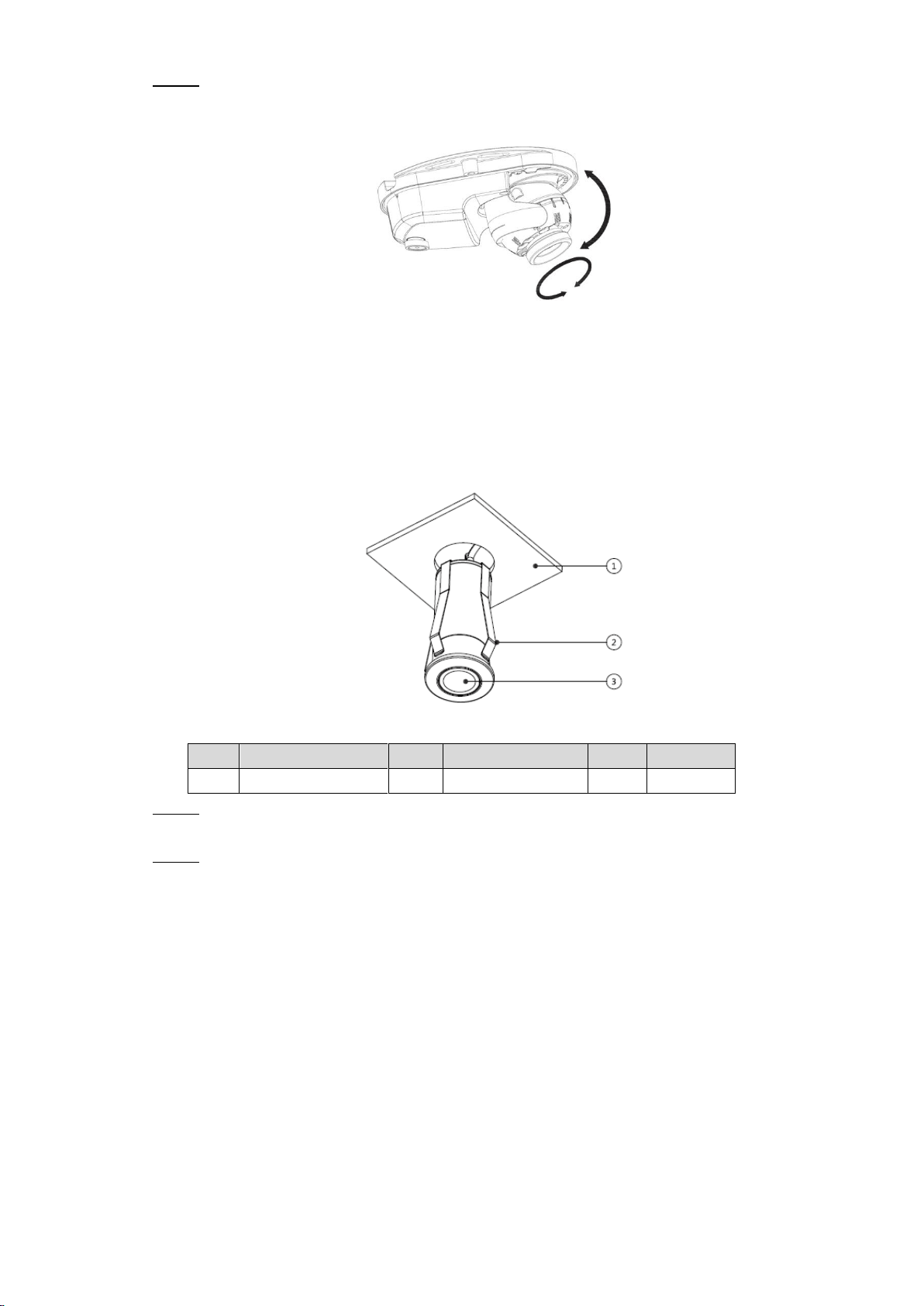
Put the enclosure⑥ back on and adjust the locking screws⑦/⑧ to hold it. Connect the Step 4
device⑤ to power source and HCVR, aim the lens to the ideal angle (see Figure 3-3)
and fasten the locking screws⑦/⑧.
Adjusting Model B Figure 3-3
Installation 7
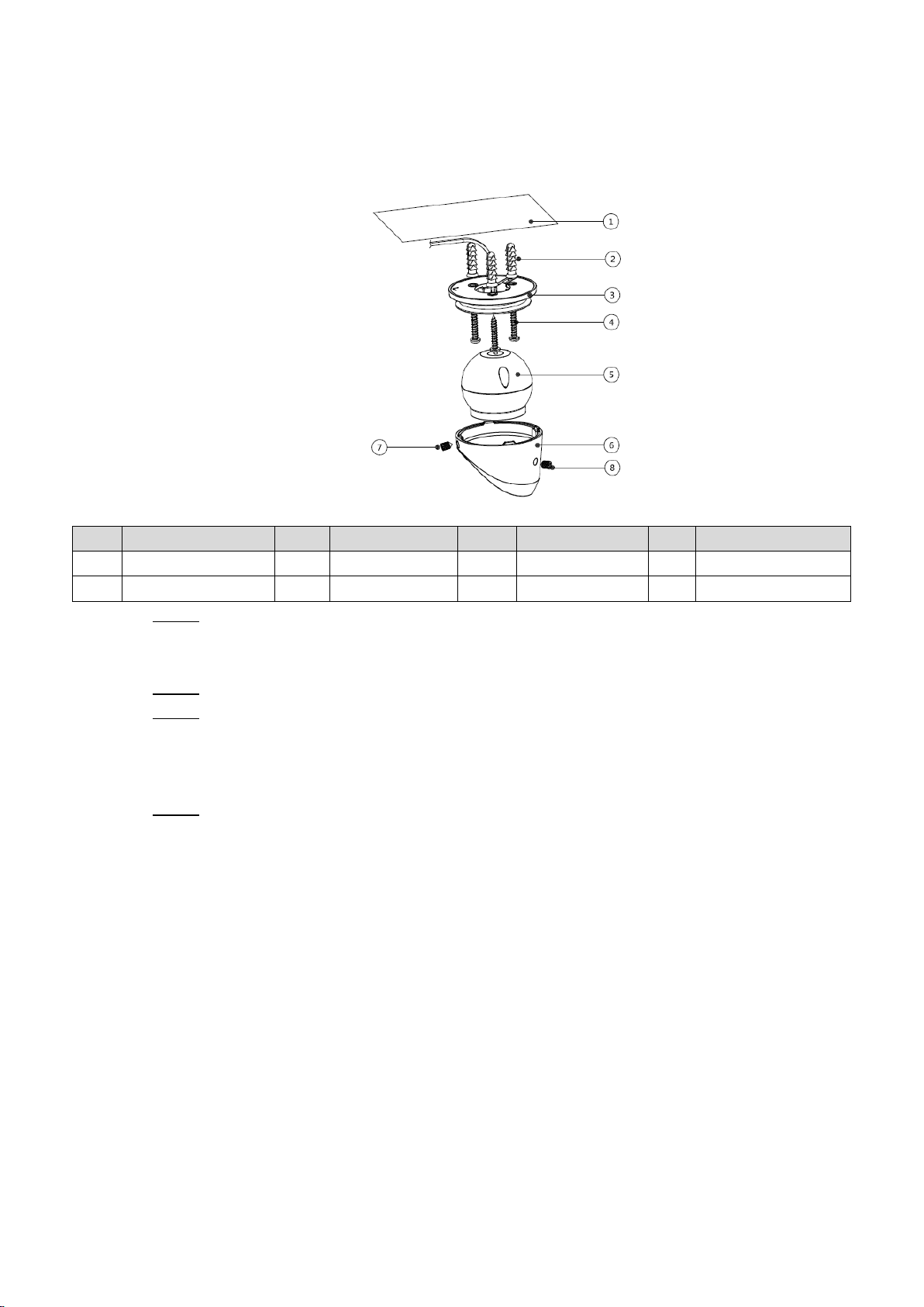
3.3 Installing Model C
Screw cover is available on select models.
For the installation diagram and item list of model C, see Figure 3-4 and Table 3-3.
Model C installation diagram Figure 3-4
Table 3-3 Model C installation item list
No.
Item
No.
Item
No.
Item
No.
Item
①
Mounting surface
②
Expansion bolt
③
Pedestal
④
Self-tapping screw
⑤
Locking screw
⑥
Dome
⑦
Wrench
⑧
Screw Cover
Drill screw holes (and the cable outlet hole if it needs to go through the mounting Step 1
surface) on the mounting surface① as indicated on the positioning map, then insert
expansion bolts② in the screw holes.
Loosen the locking screws⑤ on the dome⑥ with the supplied wrench⑦ and take the Step 2
dome⑥ off.
Adjust the location of the pedestal③ according to cable outlet requirement (top out or Step 3
side out), then pull the cable out through mounting surface or the side cable tray. Align
the screw holes on the pedestal③ to those on the mounting surface.
Put the screw covers⑧ in the screw holes on the pedestal③, then put the supplied Step 4
self-tapping screws④ through the screw covers⑧ and fasten them to attach the
device to the mounting surface.
Installation 8
Connect the camera to power source and HCVR, and aim the lens to the ideal angle, Step 5
see Figure 3-5. Put the Dome⑥ back on and fasten the locking screws⑤.
Adjusting Model C
Figure 3-5
3.4 Installing Model D (1)
For the installation diagram and item list of model D (1), see Figure 3-6 and Table 3-4.
Model D (1) installation diagram Figure 3-6
Table 3-4 Model D (1) installation item list
No.
Item
No.
Item
No.
Item
①
Mounting surface
②
Clamp
③
Device
Pull the cable through mounting surface① and attach the device③ to the mounting Step 1
surface① with the clamp②.
Reinforce the device③ to the mounting surface① by putting more sealant to the joint. Step 2
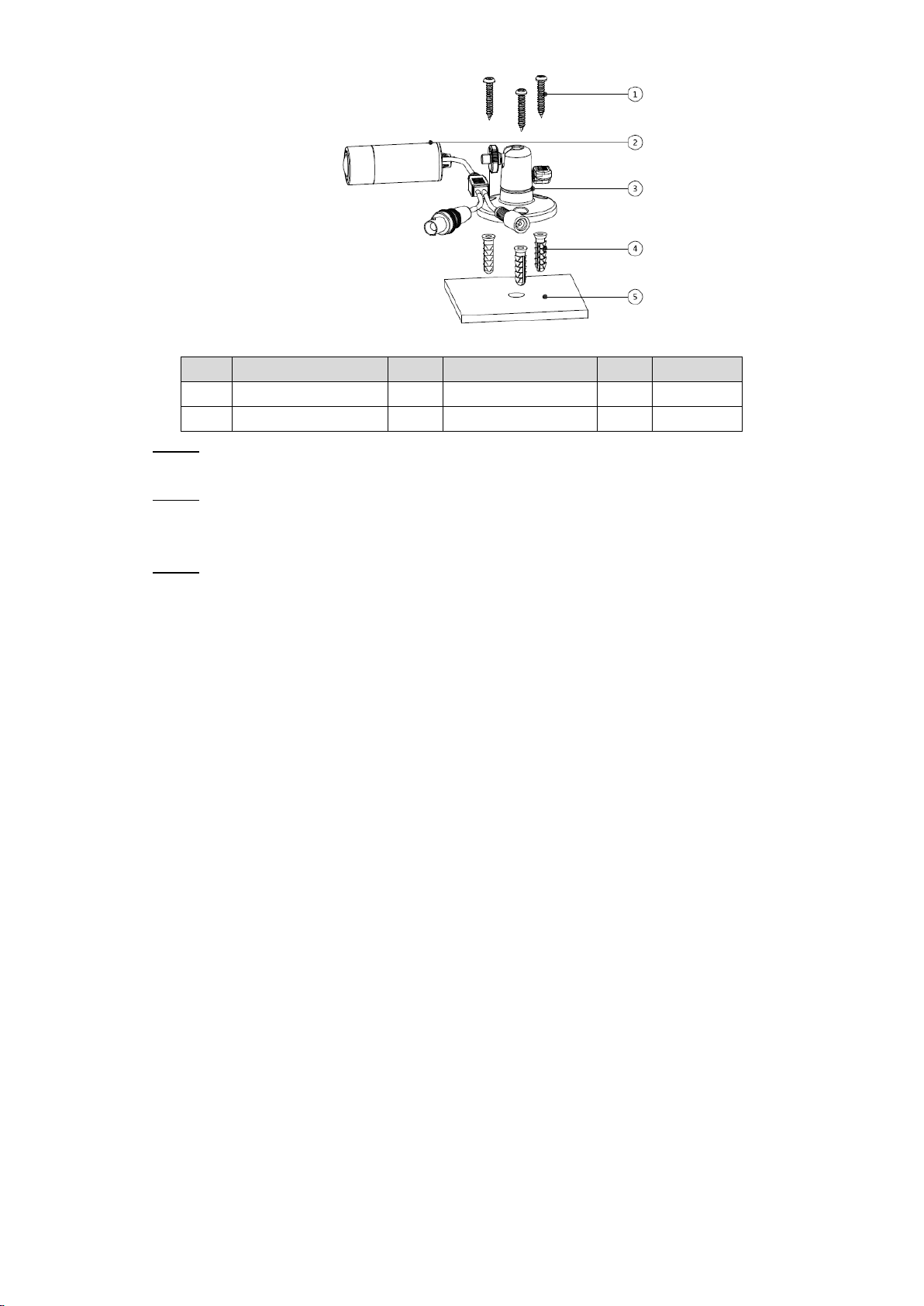
3.5 Installing Model D (2) and Model D (3)
For the installation diagram and item list of Model D (2) and Model D (3), see Figure 3-7 and
Table 3-5.
Model D (2) and Model D (3) installation diagram Figure 3-7
Installation 9
Table 3-5 Model D (2) and Model D (3) installation item list
No.
Item
No.
Item
No.
Item
①
Self-tapping screw
②
Device
③
Pedestal
④
Expansion bolt
⑤
Mounting surface
—
—
Drill screw holes on the mounting surface⑤, then insert expansion bolts④ in the screw Step 1
holes.
Align the screw holes on the pedestal③ to those on the mounting surface⑤, then put Step 2
in and fasten the supplied self-tapping screws① to attach the pedestal③ to the
mounting surface.
Adjust the location of the device② on the pedestal③ and fasten the locking screw to Step 3
attach the device on the pedestal③.
Configuration 10
4 Configuration
Power up the camera and connect it to HCVR device with coaxial cable, then the main screen
is displayed. The following instructions will guide you to configure your camera.
The number of the coaxial port on HCVR will display at the lower left corner of each window to
indicate the corresponding camera.
4.1 Setting HCVR
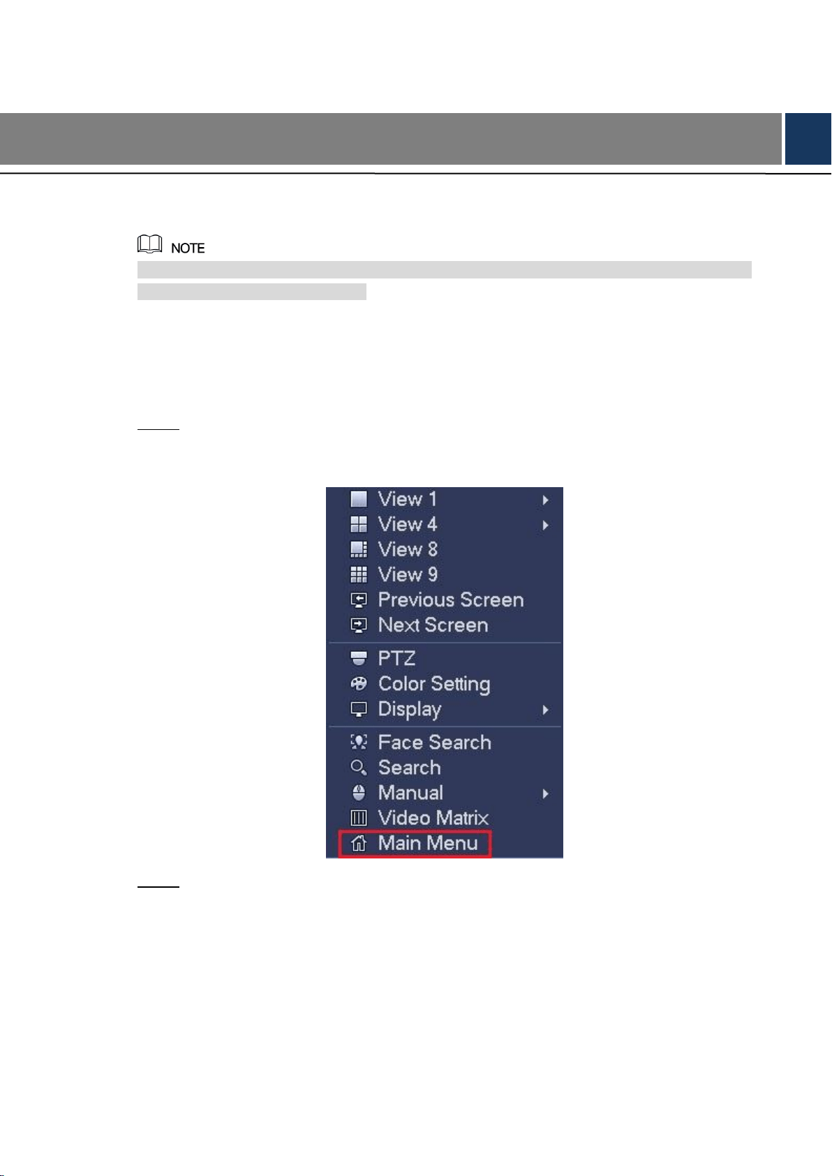
Right-click anywhere on the main screen. Step 1
The shortcut menu is displayed. See Figure 4-1.
Shortcut menu Figure 4-1
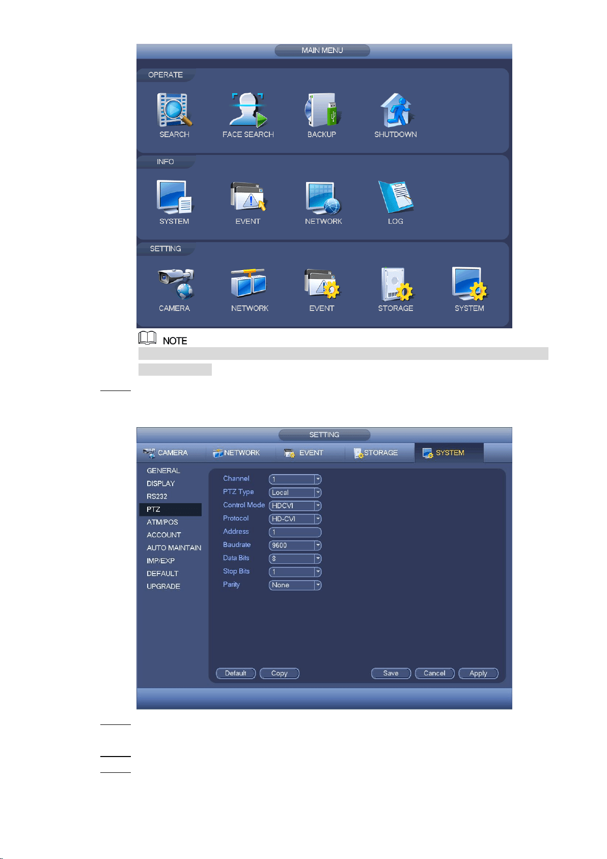
Click Main Menu. Step 2
The Main Menu interface is displayed. See Figure 4-2.
Main menu interface Figure 4-2
Configuration 11
Right-click anywhere on the screen to return to the previous menu until you goes back
to main screen.
In the SETTING column area, click SYSTEM > PTZ. Step 3
The Setting interface is displayed. See Figure 4-3.
Setting interface Figure 4-3
In the Channel list, select the camera that you want to configure according to the Step 4
coaxial port number.
In the Control Mode list, select HDCVI; In the Protocol list, select HD-CVI. Step 5
Click Save to save the settings. Step 6
Configuration 12
4.2 Setting Audio Input
Audio signal acquisition is available on select models.
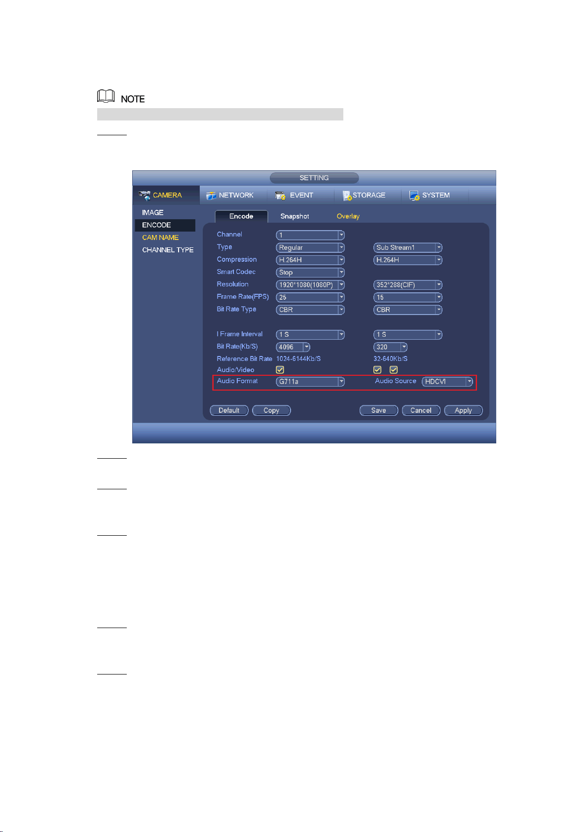
In the Main Menu interface (Figure 4-2), select CAMERA > ENCODE > Encode. Step 1
The Encode setting interface is displayed. See Figure 4-4.
Encode setting interface Figure 4-4
In the Channel list, select the camera that you want to configure according to the Step 2
coaxial port number.
Configure the audio settings. Step 3
In the Audio Format list, select G711a.
In the Audio Source list, select HDCVI.
Click Save to save the settings. Step 4
4.3 Operating OSD Menu
In the main screen, right-click within the live view window of the camera that you want Step 1
to configure.
The shortcut menu (Figure 4-1) is displayed.
Click PTZ. Step 2
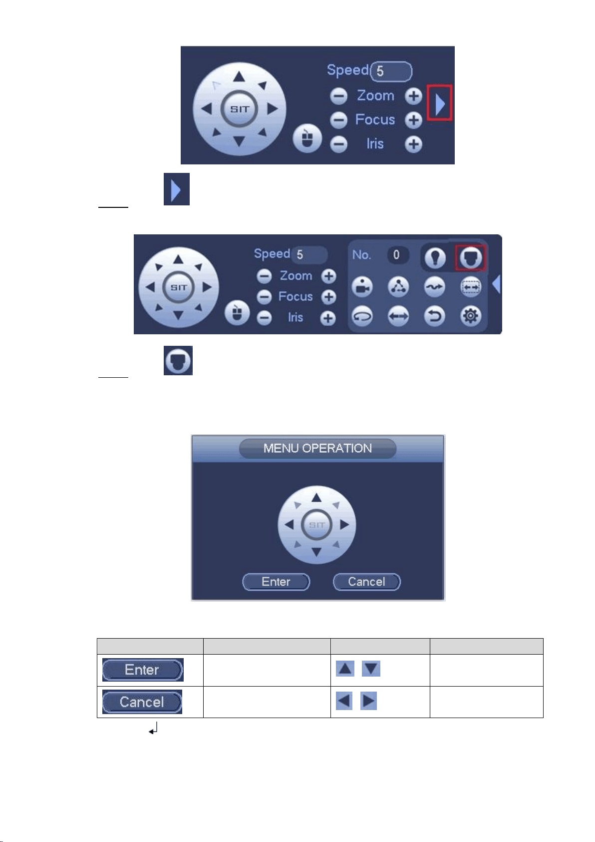
The PTZ setting interface is displayed. See Figure 4-5.
PTZ setting interface Figure 4-5
Configuration 13
Click to see more options. See Figure 4-6. Step 3
PTZ setting options Figure 4-6
Click . Step 4
The MENU OPERATION panel is displayed. See Figure 4-7.
The OSD menu of the corresponding camera is displayed on the live view screen.
Menu Operation panel Figure 4-7
For the function of the buttons in the MENU OPERATION panel, see Table 4-1.
Table 4-1 Menu Operation panel function
Button
Function
Button
Function
Enter or confirm an item
,
Select item
Exit OSD menu
,
Change item value
If there is " " as the value of an OSD item, click Enter to go to the next level of this item. Click
Return to go back to the previous level. Clicking Cancel is to exit OSD menu without saving the
modifications.

Configuration 14
Interfaces of different HCVR might vary, and the actual product shall prevail.
The OSD menus of different cameras might vary, and the actual product shall prevail.

Maintenance 15
5 Maintenance
In order to maintain the image quality and proper functioning of the device, please read the
following maintenance instructions carefully and hold rigid adherence.
Disassembly and Desiccant Replacement
Carefully follow the instructions in the manual when performing any disassembly operation
about the device; otherwise, it might cause water leakage or poor image quality due to
unprofessional disassemble.
Please contact after-sale service for desiccant replacement if there is condensed fog found
on the lens after unpacking or when the desiccant turns green. (Not all models are included
with the desiccant).
Maintaining Lens and Mirror Surface
The lens and mirror surface are covered with antireflection coating, which could be
contaminated or damaged and result in lens scratches or haze image when being touched
with dust, grease, fingerprints and other similar substances.
Do not touch the image sensor directly (CCD or CMOS). Dust and dirt could be removed
with air blower, or you can wipe the lens gently with soft cloth that moistened with alcohol.
Maintaining Device Body
Device body can be cleaned with soft dry cloth, which can also be used to remove
stubborn stains when moistened with mild detergent.
To avoid possible damage on device body coating which could cause performance
decrease, do not use volatile solvent such as alcohol, benzene, diluent and so on to clean
the device body, nor can strong, abrasive detergent be used.
Maintaining Dome Cover
Dome cover is an optical component, do not touch or wipe the cover with your hands directly
during installation or operation. The following approaches can be used to deal with possible
contamination.
Removing Dust
Wipe gently with non-oil soft brush or use air blower.
Removing Grease or Fingerprints
Wipe the cover gently with soft cloth to make it day, then moisten oil-free soft cloth or lens
cleaning paper with alcohol or lens cleaner and wipe the cover gently. You may perform
repeatedly until the cover is clean.