Owner'sIVlanual/iVlanualDel Propietario
[
GarageDoorOpenerWiTHAssureLinkTM CONNECTiViTY
Abridorde puertade cocheraCONCONECTiVOAssureLinkTM
ForResidentialUseOnly/S61oparausoresidential
IViODEL/iViODELO139.30437
J=R
Z
i,m
m
gO
Z
rT'i
go
Z_
O
r""
Readand followall safetyrulesand operating
instructionsbefore first use of thisproduct.
Fastenthe manual nearthe garage doorafter
installation.
Periodic checksof the opener are requiredto
ensuresafe operation.
DO NOTenablethe Timer-to-Closefeature if
you are installingthe garage door openeron a
one-piece door. The Timer-to-Closeis to be
used ONLYwith sectionaldoors.
Leery seguirtodasias regias de seguridady
las instruccionesde operaci6n antesde usar
este productoporprimeravez.
Guardareste manual cercade la puertade la
cochera.
Se deben realizar revisionesperi6dicasdei
abridor de puertaspara asegurar su operaci6n
segura.
NO uso el caracteristicaTernporizadorpara
cierra se el abridor de la puertaes instalado
en un puertade un sola pieza. E!caracteristica
ternporizador para cierra es SOLOpara uso
con puertasseccionales.
Sears BrandsManagementCorporation, HoffrnanEstates,IL 50179 U.S.A.
www.craftsman.com
TABLE OF CONTENTS
Introduction 2-7
Safety symbol and signal word review ..................... 2
Preparing your garage door ............................. 3
Tools needed ........................................ 3
Planning ........................................... 4-5
Carton inventory ...................................... 6
Hardware inventory.................................... 7
Assembly 8-11
Assemble the rail and install the trolley .................... 8
Fastenthe rail to the motor unit .......................... 8
install the idler pulley .................................. 9
Install the chain/cable................................. 10
Tighten the chain .................................... 11
/nstallation 11-27
Installation safety instructions .......................... 11
Determine the headerbracket location .................... 12
install the header bracket .............................. 13
Attach the rail to the headerbracket...................... 14
Position the opener................................... 15
Hang the opener ..................................... 16
install the lights ..................................... 17
Attach the emergency release rope and handle ............. 17
Fastenthe door bracket ............................. 18-19
Connect the door arm to trolley ....................... 20-21
Attach the warning labels .............................. 21
install the door control ................................ 22
install The Protector System_ ......................... 23-25
Electrical requirements ................................ 26
Aligning the safety reversingsensors ..................... 27
Adjustment 28-30
introduction ........................................ 28
Program the travel ................................... 29
Test the safety reversal system.......................... 30
Test The Protector System_ ............................ 30
Operation 31-35
Operation safety instructions ........................... 31
Features ......................................... 31-32
Door control ........................................ 32
Motion-detecting control panelsetup ..................... 33
Programming ....................................... 34
To erasethe memory ................................. 34
To open the door manually............................. 35
Care of your opener .................................. 35
Troubleshooting 38-37
Repair Parts 38-39
Rail assembly parts .................................. 38
installation parts ..................................... 38
Motor unit assembly parts ............................. 39
Accessories 40
Warranty 40
Notes 41
Repair Parts and Service
Back Cover
INTRODUCTION
Safety Symbol and Signal Word Review
This garage door opener has beendesigned and tested to offer safe service provided it is installed, operated, maintained and tested in
strict accordancewith the instructions and warnings contained in this manual.
Mechanical
Electrical
When you see these Safety Symbols and Signal Words on the
following pages,they will alert you to the possibility of serious
injury or death if you do not comply with the warnings that
accompanythem. The hazard may come from something
mechanical or from electric shock. Readthe warnings carefully.
When you see this Signal Word on the following pages, it will
alert you to the possibility of damageto your garagedoor and/or
the garagedoor opener if you do not comply with the cautionary
statements that accompany it. Readthem carefully.
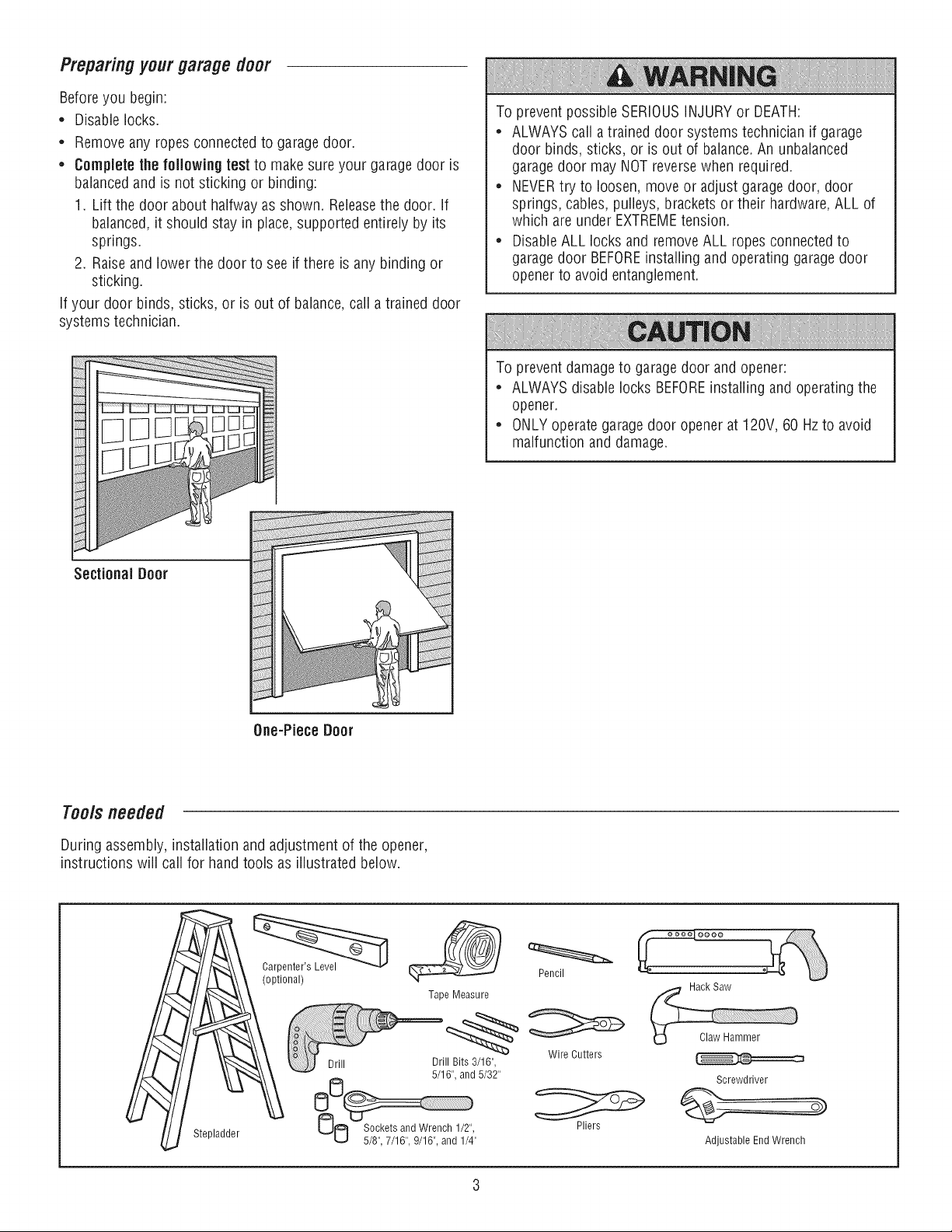
Preparing your garage door
Before you begin:
* Disable locks.
* Remove any ropes connected to garage door.
, Complete the following test to make sure your garage door is
balancedand is not sticking or binding:
1. Lift the door about halfway as shown. Releasethe door. If
balanced,it should stay in place, supported entirely by its
springs.
2. Raiseand lower the door to see if there is any binding or
sticking.
If your door binds, sticks, or is out of balance,call a trained door
systems technician.
To prevent possible SERIOUSINJURYor DEATH:
* ALWAYScall atrained door systems technician if garage
door binds, sticks, or is out of balance.An unbalanced
garagedoor may NOT reverse when required.
, NEVERtry to loosen, move or adjust garage door, door
springs, cables, pulleys, brackets or their hardware, ALL of
which are under EXTREMEtension.
, DisableALL locks and removeALL ropes connected to
garagedoor BEFOREinstalling and operating garagedoor
opener to avoid entanglement.
To prevent damageto garage door and opener:
* ALWAYSdisable locks BEFOREinstalling and operating the
opener.
, ONLYoperate garagedoor opener at 120V, 60 Hzto avoid
malfunction and damage.
SectionaJ Door
One-Piece Door
Too/sneeded
During assembly, installation and adjustment of the opener,
instructions will call for hand tools as illustrated below.
Stepladder
Carpenter's Level (__
(optional) Pencil
Tape Measure
Drill Drill Bits3/16", WireCutters
O0 5/16",and5/32"
O0 _OsC,k_/_ _n,d_e,nc_dll2/i,, Pliers
Screwdriver
Adjustable End Wrench
P nnMg
identify the type and height of your garage door. Survey your
garageareato see if any of the conditions below apply to your
installation. Additional materials may be required. You may find it
helpful to refer back to this page andthe accompanying
illustrations as you proceed with the installation of your opener.
Depending on your requirements,there are several installation
steps which may call for materials or hardware not included in the
carton.
• Installation Step 1 - Look at the wall or ceiling above the
garagedoor. The header bracket must be securely fastened to
structural supports.
• Installation Step 5 - Do you have a finished ceiling in your
garage? if so, a support bracket and additional fastening
hardware may be required.
• installation Step 12- Dependingupon garageconstruction,
extension brackets or wood blocks may be needed to install
sensors.
• installation Step 12- Alternate floor mounting of the safety
reversingsensor will require hardware not provided.
Do you have an accessdoor in addition to the garage door? if
not, Model 139.53702 EmergencyKey Releaseis required. See
Accessories page.
Look at the garagedoor where it meets the floor. Any gap
betweenthe floor and the bottom of the door must not exceed
1/4" (6 mm). Otherwise,the safety reversal system may not
work properly. SeeAdjustment Step 2. Floor or door should be
repaired.
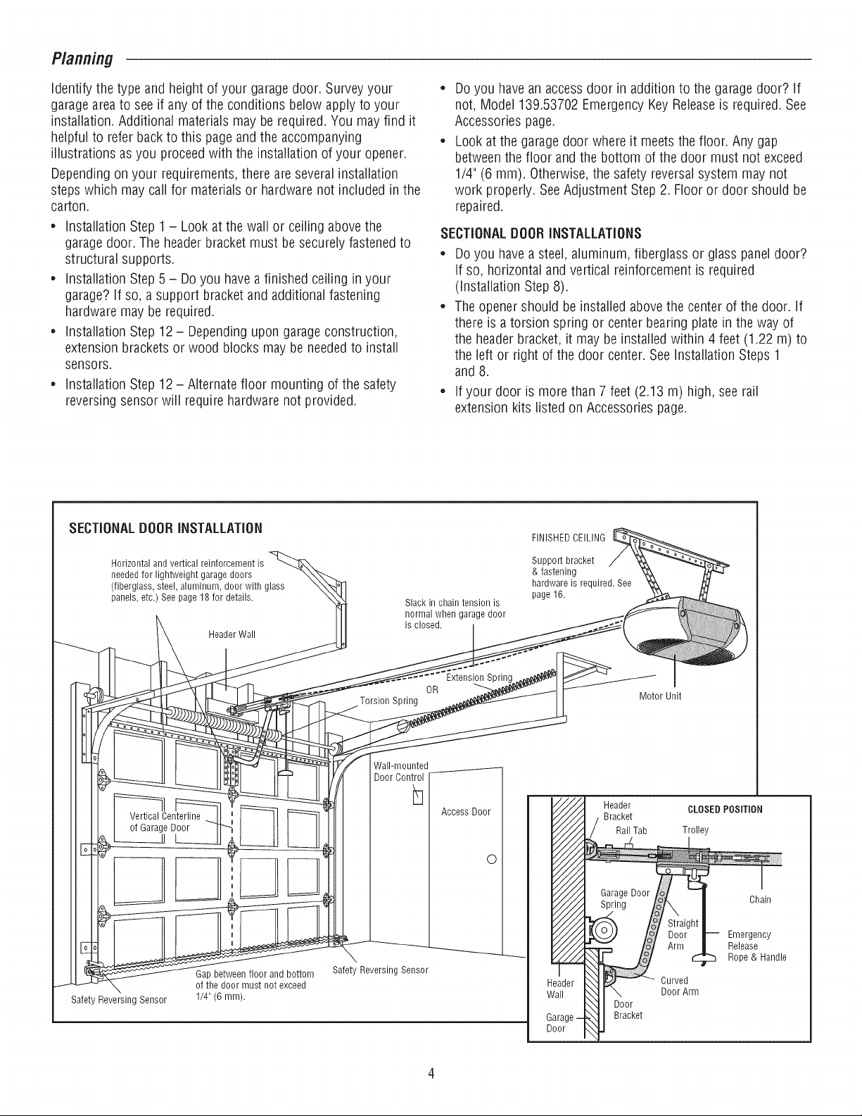
SECTIONALDOORINSTALLATIONS
• Do you have a steel, aluminum, fiberglass or glass panel door?
if so, horizontal and vertical reinforcement is required
(installation Step 8).
• The opener should be installed above the center of the door. if
there is a torsion spring or center bearing plate in the way of
the headerbracket, it may be installed within 4 feet (1.22 m) to
the left or right of the door center. See installation Steps 1
and 8.
• If your door is more than 7 feet (2.13 m) high, see rail
extension kits listed on Accessories page.
SECTIONALDOORINSTALLATION
Horizontal and vertical reinforcement is
needed for lightweight garage doors
(fiberglass, steel, aluminum, door with glass
panels, etc.) See page 18 for details.
Header Wall
Slack in chain tension is
normal when garage door
is closed.
FINISHED CEILING
SuppoR bracket
& fastening
hardware is required. See
page 16.
OR
Torsion Spring
Sprin,
Motor Unit
Vertical Centerline
of Garage Door
Safety Reversing Sensor
Gap between floor and bottom
of the door must not exceed
1/4" (6 mm).
Wall-mounted
Door Control
h
Safety Reversing Sensor
Access Door
O
Header
Bracket
Rail Tab
CLOSEDPOSITION
Trolley
Garage Door
Spring
Door
Bracket
Cuwed
Door Arm
Chain
Emergency
Release
Rope & Handle
Planning(Continued)
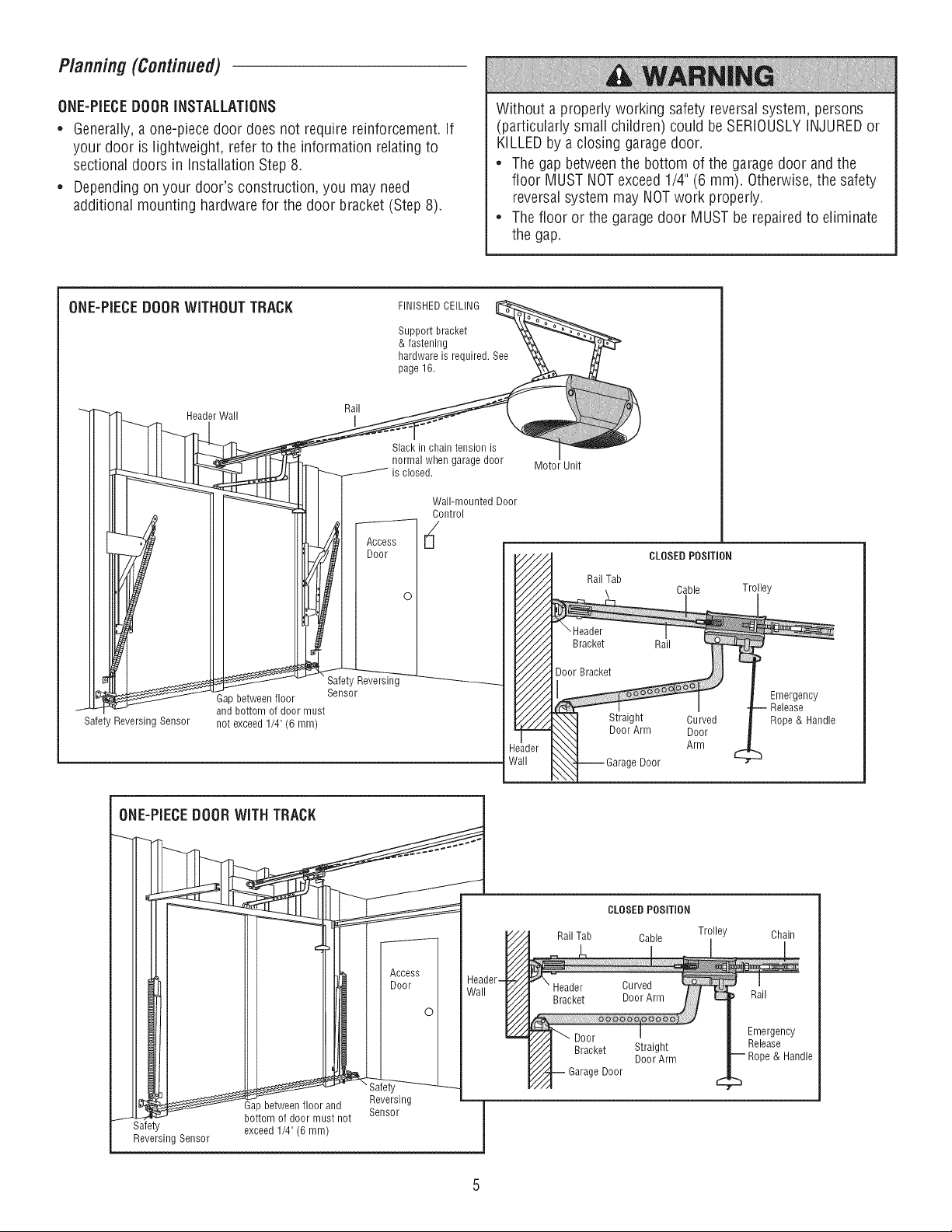
ONE-PIECEDOORINSTALLATIONS
* Generally,a one-piece door does not require reinforcement, if
your door is lightweight, refer to the information relating to
sectional doors in Installation Step 8.
* Dependingon your door's construction, you may need
additional mounting hardware for the door bracket (Step 8).
Without a properly working safety reversal system, persons
(particularly small children) could be SERIOUSLYINJUREDor
KILLEDby a closing garagedoor.
* The gap between the bottom of the garage door and the
floor MUST NOTexceed1/4" (6 mm). Otherwise, the safety
reversalsystem may NOTwork properly.
* The floor or the garage door MUST be repairedto eliminate
the gap.
ONE-PIECEDOORWITHOUTTRACK FINISHEDCEILING__
Support bracket _ _ ._-"_
& fastening _ _l_r _'
hardware is required. See "_
page 16.
Header Rail
W_sr
-- -_]1_-----f-_ is'c'lo_;d'................ Motor Unit
__L_ _ Wall-mounted Door
____,,,_- _-- __1 Door Bracket
Safety Reversing
Gap between floor Sensor
t and bottom of door must
Safety Reversing Sensor not exceed 1/4" (6 mm)
Door
CLOSED POSiTiON
Cable Trolley
Curved
Door
Arm
Emergency
Release
Rope & Handle
ONE-PIECEDOORWITH TRACK
Gap between floor and
bottom of door must not Sensor
l
Safety exceed 1/4" (6 mm)
Reversing Sensor
CLOSED POSITION
Rail Tab Cable Trolley
Chain
Rail
e Door
Straight
DoorArm
Emergency
Release
& Handle
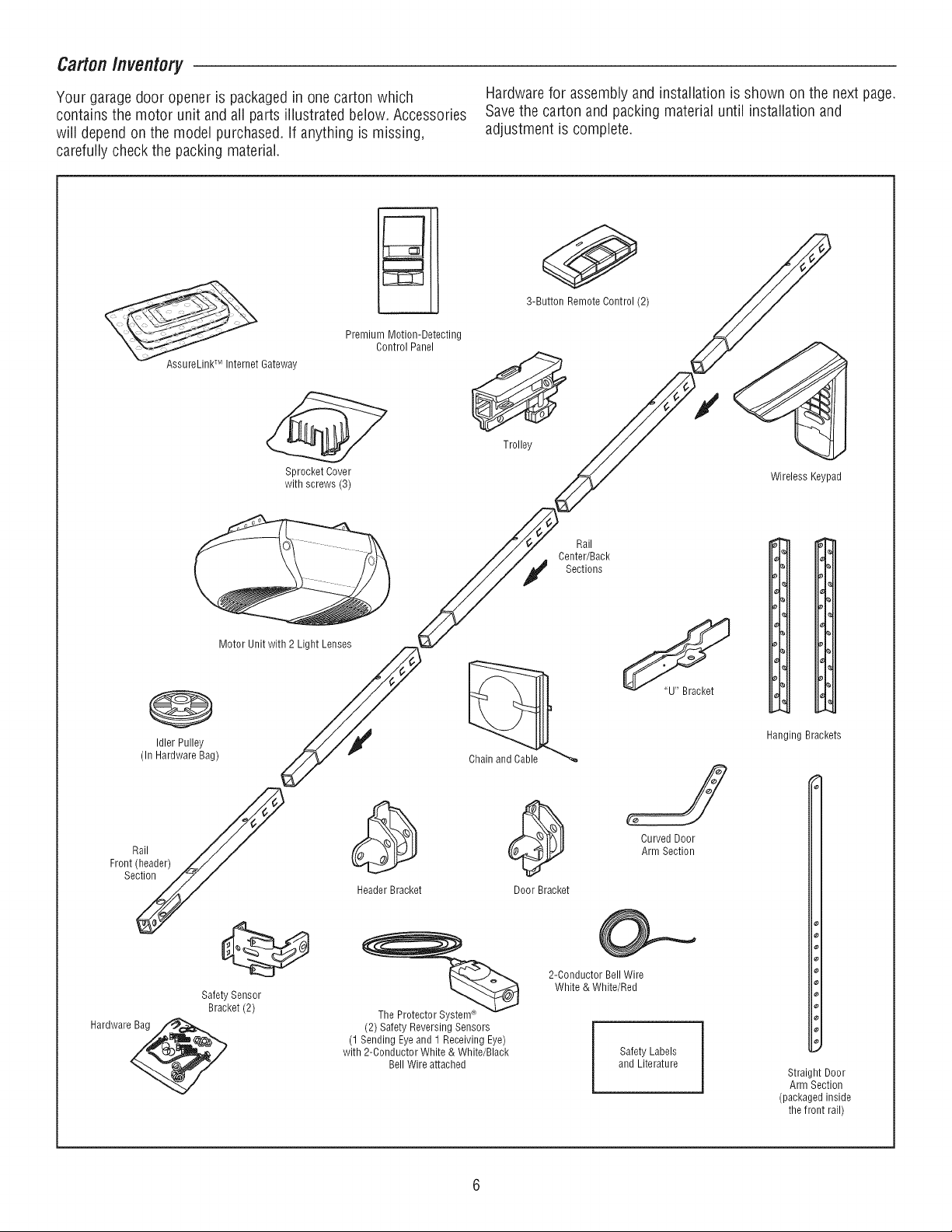
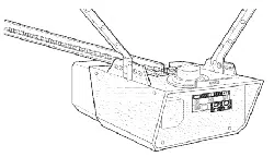
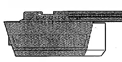
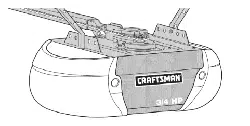
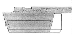
Carton Inventory
Your garage door opener is packaged in one carton which
contains the motor unit and all parts illustrated below. Accessories
will depend on the model purchased. If anything is missing,
carefully check the packing material.
Hardwarefor assembly and installation is shown on the next page.
Savethe carton and packing material until installation and
adjustment is complete.
AssureLinkTM Internet Gateway
Premium Motion-Detecting
Control Panel
Sprocket Cover
with screws (3)
3-Button Remote Control (2)
Trolley
Wireless Keypad
Motor Unit with 2 Light Lenses
0
Idler Pulley
(In Hardware Bag)
Rail
Front (header)
Section
Safety Sensor
Bracket (2)
Hardware@
Rail
Center/Back
Sections
Header Bracket Door Bracket
S
Curved Door
Arm Section
%
The Protector System_
(2) Safety Reversing Sensors
(1 Sending Eyeand 1 Receiving Eye)
with 2-Conductor White & White/Black
Bell Wire attached
2-Conductor Bell Wire
White & White/Red
Safety Labels
and Literature
Hanging Brackets
Straight Door
Arm Section
(packaged inside
the front rail)
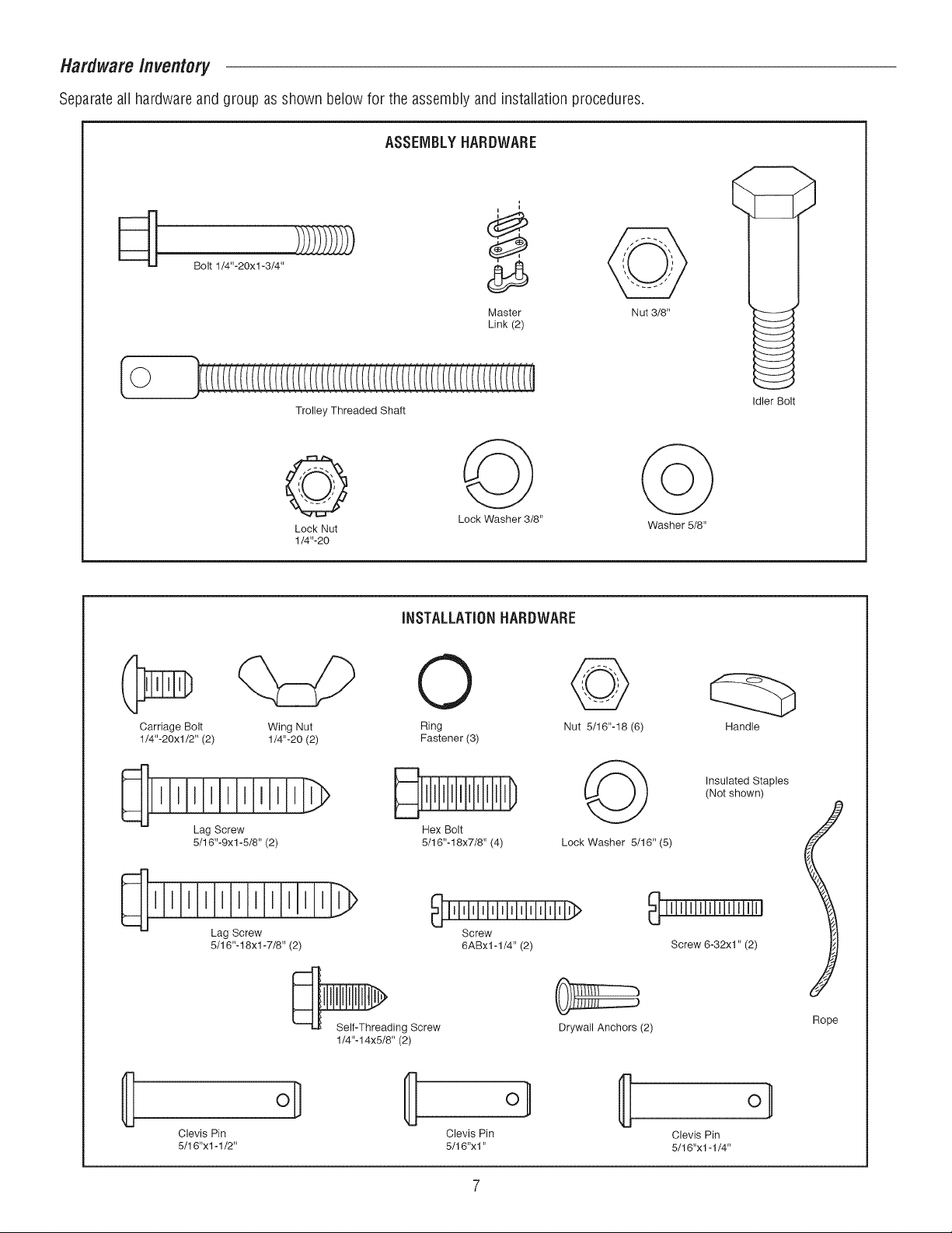
Hardware/nventory
Separateall hardware and group as shown below for the assembly and installation procedures.
ASSEMBLYHARDWARE
i
Bolt 1/4"-20xl -3/4"
Master
Link (2)
Nut 3/8"
Trolley Threaded Shaft
Lock Washer 3/8"
Lock Nut Washer 5/8"
1/4"-20
Idler Bolt
INSTALLATIONHARDWARE
Carriage Bolt
1/4"-20xl/2" (2)
Wing Nut
1/4"-20 (2)
Lag Screw
5/16"-9xl -5/8" (2)
lllllllllllllllllllll
Lag Screw
5/16"-18xl -7/8" (2)
0
Ring
Fastener (3)
Hex Bolt
5/16"-18x7/8" (4)
Screw
6ABx1-1/4" (2)
Self-Threading Screw
1/4"-14x5/8" (2)
oH
Clevis Pin Clevis Pin
5/16"x 1-1/2" 5/16"xl"
Nut 5/16"-18 (6)
Handle
Lock Washer 5/16" (5)
Insulated Staples
(Not shown)
Screw 6-32xl" (2)
Drywall Anchors (2)
Clevis Pin
5/16"xl -1/4"
J
Rope
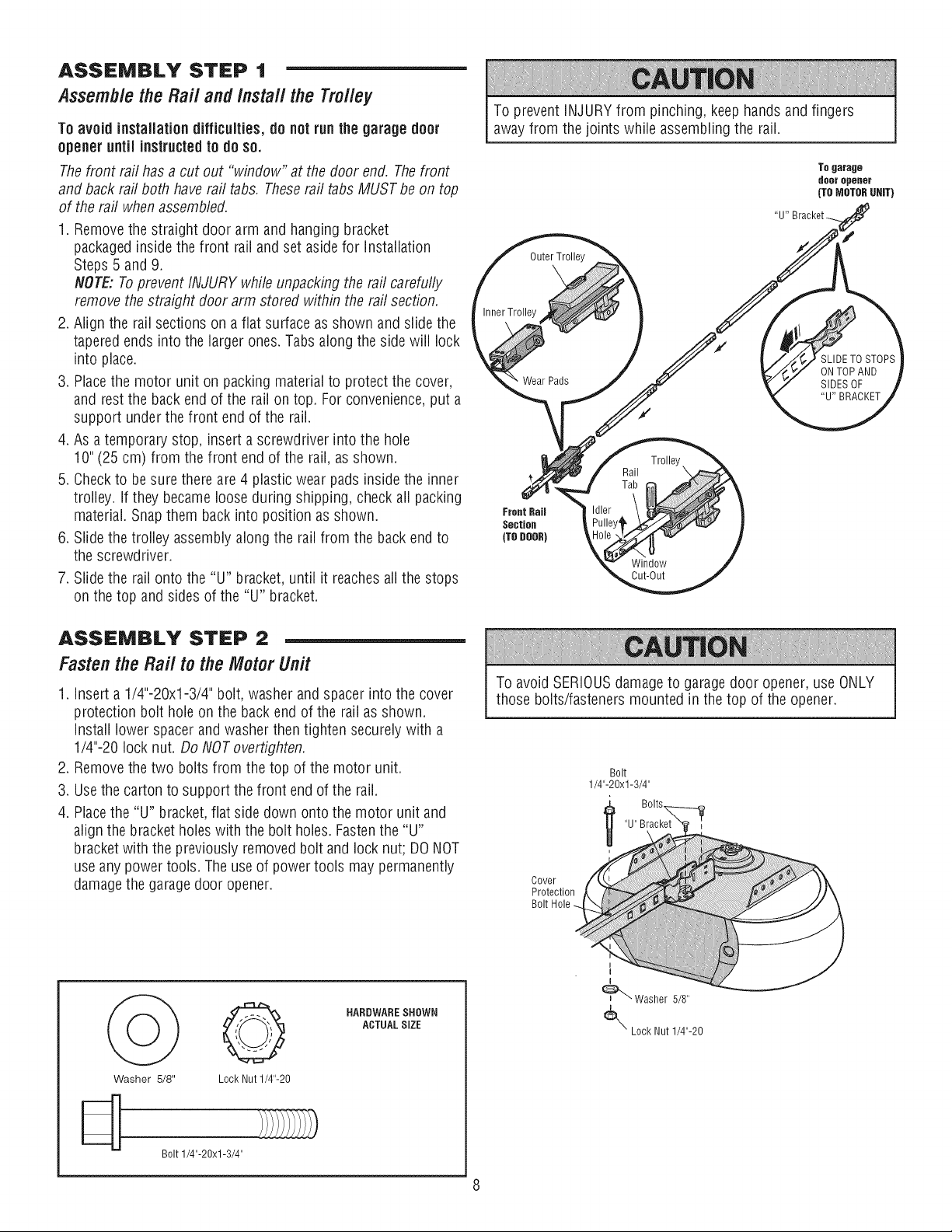
ASSEMBLY STEP 1
Assemblethe Rail and install the Trolley
To avoid installation difficulties, do not runthe garage door
opener until instructedto do so.
The front rail has a cut out "window" at the door end. The front
and back rail both have rail tabs. These rail tabs MUST be on top
of the rail when assembled.
1. Removethe straight door arm and hanging bracket
packagedinside the front rail and set aside for Installation
Steps 5 and 9.
NOTE:To prevent INJURY while unpacking the rail carefully
remove the straight door arm stored within the rail section.
2. Align the rail sections on a fiat surface as shown and slide the
tapered ends into the larger ones. Tabs along the side will lock
into place.
3. Placethe motor unit on packing material to protect the cover,
and rest the back end of the rail on top. For convenience,put a
support under the front end of the rail.
4. As a temporary stop, insert a screwdriver into the hole
10" (25 cm) from the front end of the rail, as shown.
5. Checkto besure there are 4 plastic wear pads inside the inner
trolley, if they becameloose during shipping, check all packing
material. Snap them back into position as shown.
6. Slide the trolley assembly along the rail from the back end to
the screwdriver.
7. Slide the rail onto the "U" bracket, until it reaches all the stops
on the top and sides of the "U" bracket.
ASSEMBLY STEP 2
Fastenthe Rail to the Motor Unit
1. insert a 1/4"-20xl-3/4" bolt, washer and spacer into the cover
protection bolt hole on the back end of the rail as shown.
Install lower spacer and washer then tighten securely with a
1/4"-20 lock nut. Do NOTovertighten.
2. Removethe two bolts from the top of the motor unit.
3. Usethe carton to support the front end of the rail.
4. Placethe "U" bracket, flat side down onto the motor unit and
align the bracket hobs with the bolt hobs. Fastenthe "U"
bracketwith the previously removed bolt and lock nut; DONOT
use any power tools. The use of power tools may permanently
damage the garage door opener.
To prevent iNJURY from pinching, keep hands and fingers
away from the joints while assembling the rail.
To garage
doer opener
(TOMOTORgRiT)
Outer Trolle
Inner Trolley
Wear Pads
SLIDETO STOPS
ONTOPAND
SIDES OF
"U"BRACKET
Trolley
Rail \
Front RaU
Section
(TODOOR)
Window
Cut-Out
To avoid SERIOUSdamage to garagedoor opener, use ONLY
those bolts/fasteners mounted in the top of the opener.
Bolt
1/4"-20xl-3/4"
"U" Bracket
O
Washer 5/8" Lock Nut 1/4"-20
Bolt1/4"-20xl-3/4"
HARDWARESHOWN
ACTUAL SiZE
L
I
_ Washer 5/8"
_L_" Lock Nut 1/4"-20
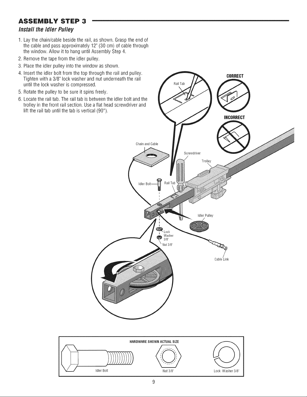
ASSEMBLY STEP 3
/nsta// the /d/er Pu//ey
1. Lay the chain/cable besidethe rail, as shown. Grasp the end of
the cable and pass approximately 12" (30 cm) of cable through
the window. Allow it to hang until Assembly Step 4.
2. Removethe tape from the idler pulley.
3. Placethe idler pulley into the window as shown.
4. Insert the idler bolt from the top through the rail and pulley.
Tighten with a 3/8" lock washer and nut underneath the rail
until the lock washer is compressed.
5. Rotate the pulley to be sure it spins freely.
6. Locatethe rail tab. The rail tab is betweenthe idler bolt and the
trolley in the front rail section. Usea flat headscrewdriver and
lift the rail tab until the tab is vertical (90°).
Rail Tab
CORRECT
@
iNCORRECT
Chain and Cable
Screwdriver
Trol_,y
Idler Pulley
Washer
3/8"
Nut3/8"
Cable Link
HARDWARESHOWN ACTUALSIZE _ 1
[_ Idler Bolt Nut 3/8" Lock Washer 3/8"
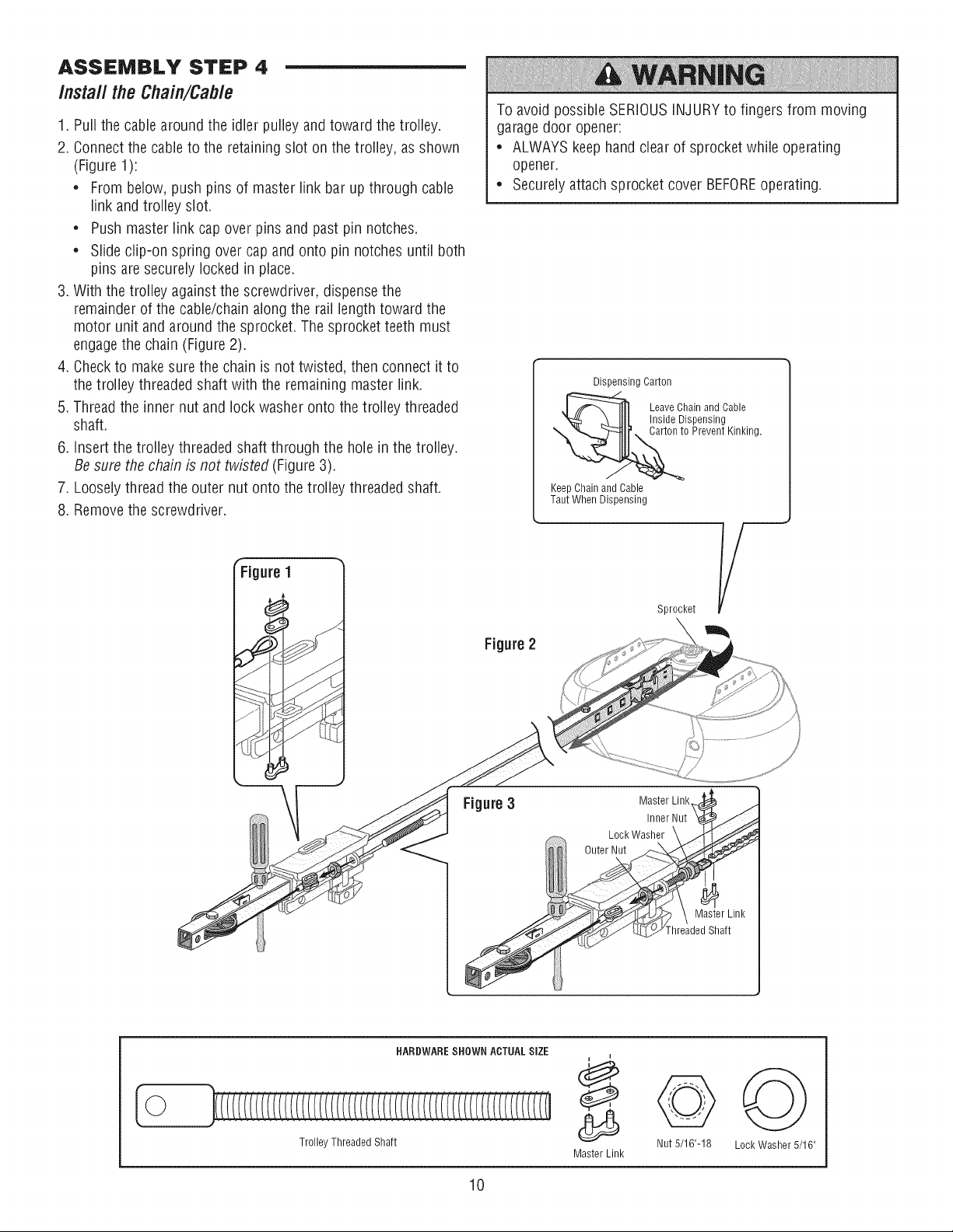
ASSEMBLY STEP 4
/nsta// the Chain/Cab/e
1. Pull the cable around the idler pulley andtoward the trolley.
2. Connect the cable to the retaining slot on the trolley, as shown
(Figure 1):
• From below, push pins of master link bar up through cable
link and trolley slot.
• Push master link cap over pins and past pin notches.
• Slide clip-on spring over cap and onto pin notches until both
pins aresecurely locked in place.
3. With the trolley against the screwdriver, dispense the
remainder of the cable/chain along the rail length toward the
motor unit and around the sprocket. The sprocket teeth must
engagethe chain (Figure 2).
4. Checkto make sure the chain is not twisted, then connect it to
the trolley threaded shaft with the remaining master link.
5. Thread the inner nut and lock washer onto the trolley threaded
shaft.
6. insert the trolley threaded shaft through the hole in the trolley.
Besure the chain is not twisted (Figure 3).
7. Looselythread the outer nut onto the trolley threaded shaft.
8. Removethe screwdriver.
ure 1
To avoid possible SERIOUSINJURYto fingers from moving
garagedoor opener:
• ALWAYS keep hand clear of sprocket while operating
opener.
• Securely attach sprocket cover BEFOREoperating.
Dispensing Carton
Leave Chain and Cable
Inside Dispensing
Carton to Prevent Kinking.
Figure2
Keep Chain and Cable
Taut When Dispensing
Sprocket
Figure3
HARDWARESHOWN ACTUAL SiZE
Trolley Threaded Shaft
Nut 5/16"-18 Lock Washer 5/16"
Master Link
10
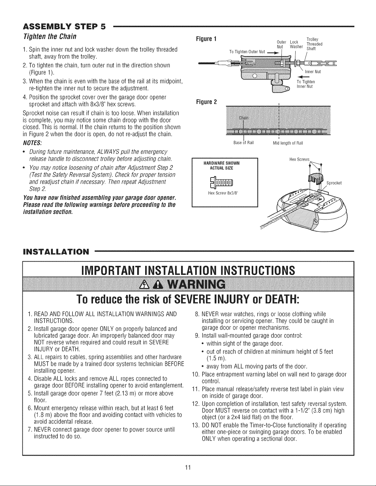
ASSEMBLY STEP 5
Tighten the Chain
1. Spin the inner nut and lock washer down the trolley threaded
shaft, away from the trolley.
2. To tighten the chain, turn outer nut in the direction shown
(Figure 1).
3. When the chain is even with the base of the rail at its midpoint,
re-tighten the inner nut to securethe adjustment.
4. Position the sprocket cover over the garage door opener
sprocket and attach with 8x3/8" hex screws.
Sprocket noise can result if chain is too loose. When installation
is complete, you may notice some chain droop with the door
closed. This is normal. If the chain returns to the position shown
in Figure 2 when the door is open, do not re-adjust the chain.
NOTES:
Figure 1 Outer Lock
Trolley
Threaded
Nut Washer Shaft
To Tighten Outer Nut
Figure 2
Base _fRail
Inner Nut
To Tighten
Inner Nut
Mid length of Rail
* During future maintenance,ALWAYS pull the emergency
releasehandle to disconnect trofley before adjusting chain.
* You may notice loosening of chain after Adjustment Step 2
(Test the Safety Reversal System). Check for proper tension
and readjust chain if necessary. Then repeatAdjustment
Step2.
Youhave nowfinished assembling your garage door opener.
Please read the following warnings beforeproceedingto the
installation section.
HARDWARESHOWN
ACTUALSiZE
Hex Screw 8x3/8"
Hex Screws
Sprocket
iNSTALLATiON
IMPORTANTINSTALLATIONINSTRUCTIONS
Toreducethe risk of SEVEREINJURYor DEATH:
1. READAND FOLLOWALL iNSTALLATiONWARNINGSAND
INSTRUCTIONS.
2. Install garagedoor opener ONLY on properly balanced and
lubricated garage door. An improperly balanceddoor may
NOT reversewhen required and could result in SEVERE
INJURYor DEATH.
3. ALL repairs to cables, spring assembliesand other hardware
MUST be made by a trained door systems technician BEFORE
installing opener.
4. DisableALL locks and removeALL ropes connected to
garagedoor BEFOREinstalling opener to avoid entanglement.
5. Install garagedoor opener 7 feet (2.13 m) or more above
floor.
6. Mount emergency releasewithin reach, but at least 6 feet
(1.8 m) abovethe floor and avoiding contact with vehicles to
avoid accidental release.
7. NEVERconnect garagedoor opener to power source until
instructed to do so.
8. NEVERwear watches, rings or loose clothing while
installing or servicing opener. They could be caught in
garage door or opener mechanisms.
9. Install wall-mounted garage door control:
* within sight of the garage door.
* out of reach of children at minimum height of 5 feet
(1.5 m).
* away from ALL moving parts of the door.
10. Placeentrapment warning label on wall next to garage door
control.
11. Placemanual release/safetyreversetest label in plain view
on inside of garage door.
12. Upon completion of installation, test safety reversal system.
Door MUST reverseon contact with a 1-1/2" (3.8 cm) high
object (or a 2x4 laid fiat) on the floor.
13. DONOTenablethe Timer-to-Close functionality if operating
either one-piece or swinging garage doors. To be enabled
ONLYwhen operating a sectional door.
11
iNSTALLATiON STEP 1
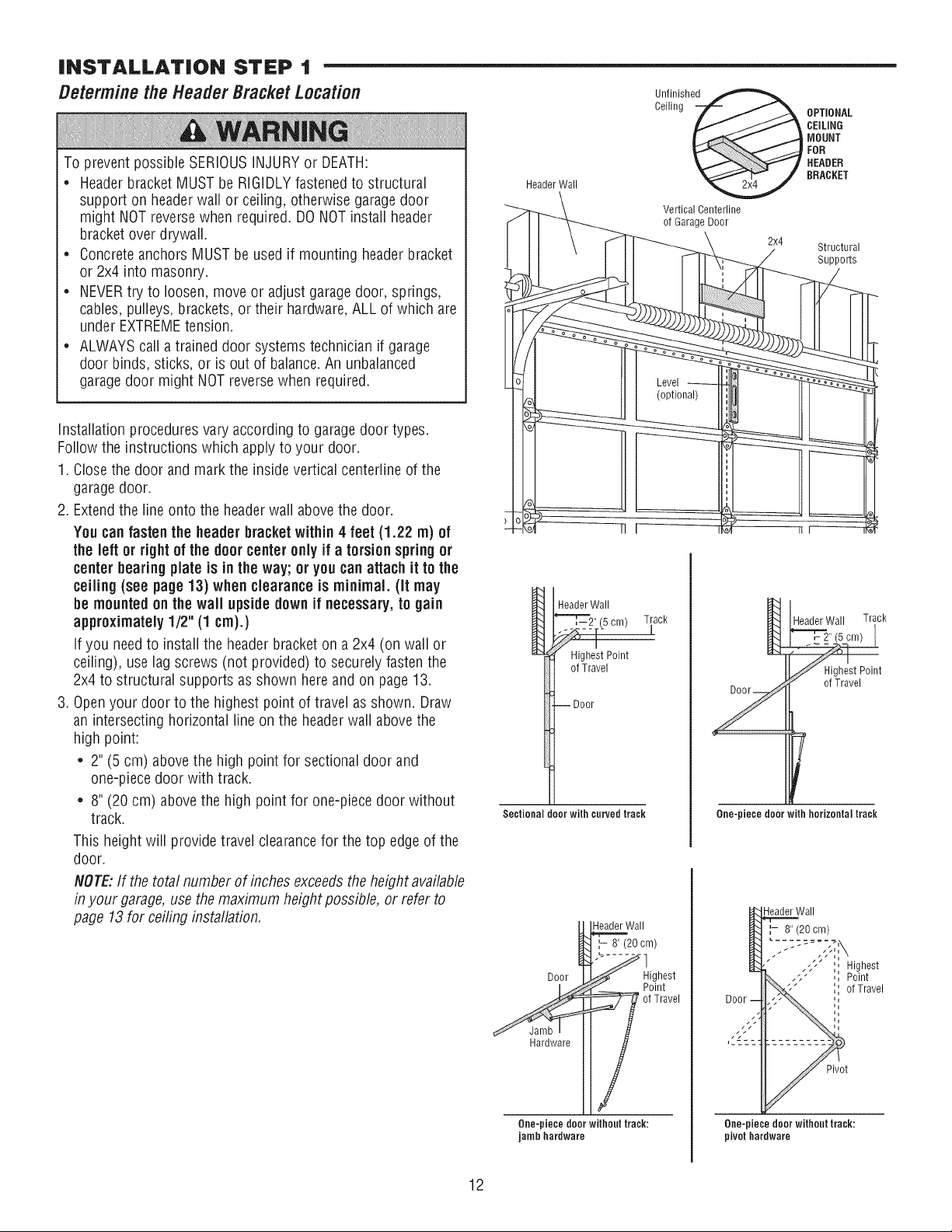
Determine the HeaderBracketLocation
To prevent possible SERIOUSINJURYor DEATH:
* Headerbracket MUST be RIGIDLY fastened to structural
support on headerwall or ceiling, otherwise garagedoor
might NOTreversewhen required. DONOT install header
bracket over drywall.
. Concrete anchors MUST be used if mounting header bracket
or 2x4 into masonry.
. NEVERtry to loosen, move or adjust garagedoor, springs,
cables, pulleys, brackets, or their hardware,ALL of which are
under EXTREMEtension.
. ALWAYScall a trained door systems technician if garage
door binds, sticks, or is out of balance.An unbalanced
garagedoor might NOTreverse when required.
Installation procedures vary according to garagedoor types.
Follow the instructions which apply to your door.
1. Closethe door and mark the inside vertical centefline of the
garagedoor.
2. Extendthe line onto the headerwail above the door.
You can fasten the header bracketwithin 4 feet (1.22 m) of
the left or rightof the door center only if a torsion springor
center bearingplate is in the way; or youcan attach it to the
ceiling (see page 13) when clearance is minimal. (it may
be mountedon the wait upsidedown if necessary,to gain
approximately 1/2" (1 cm).)
If you need to install the headerbracket on a 2x4 (on wall or
ceiling), use lag screws (not provided) to securely fasten the
2x4 to structural supports as shown hereand on page13.
3. Openyour door to the highest point of travel as shown. Draw
an intersecting horizontal line on the headerwall above the
high point:
• 2" (5 cm) above the high point for sectional door and
one-piece door with track.
• 8" (20 cm) above the high point for one-piece door without
track.
This height will provide travel clearance for the top edgeof the
door.
NOTE:If the total number of inches exceedsthe height available
in your garage, use the maximum height possible, or refer to
page 13 for ceiling installation.
Header Wall
Un.f!nished
Ceiling _ BRACKETNOUNTCEILINGOPTIONALHEADERFOR
Vertical Centerline
of Garage Door
2x4
Structural
SuppoRs
HeaderWall
_2" (5 cm) Track
i
Highest Point
of Travel
--Door
Sectional door with curved track
HeaderWall Track
Highest Point
of Travel
7
0no-piece door with horizontal track
Door
Hardware
Header Wall
',- 8" (20 cm)
Highest
Point
of Travel
One-piecedoorwithout track:
jambhardware
Door
-leader Wall
8" (20 cm)
Highest
Point
of Travel
Pivot
0no-piece door without track:
pivothardware
12
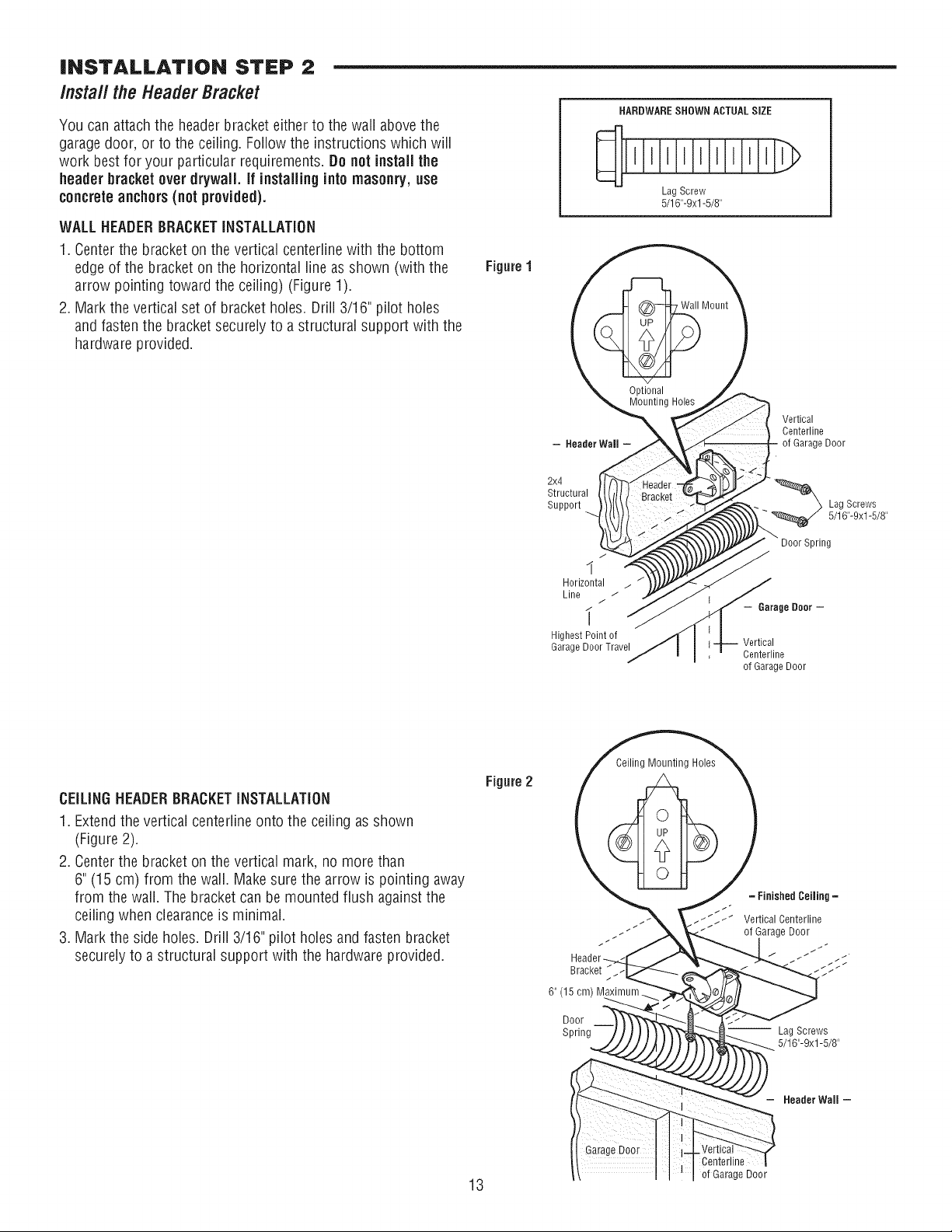
iNSTALLATiON STEP 2
Install the Header Bracket
You can attach the headerbracket either to the wall above the
garagedoor, or to the ceiling. Follow the instructions which will
work best for your particular requirements. Do not install the
header bracketover drywall. If installing into masonry,use
concreteanchors (not provided).
WALL HEADERBRACKETINSTALLATION
1. Centerthe bracket on the vertical centeriinewith the bottom
edge of the bracket on the horizontal line as shown (with the
arrow pointing toward the ceiling) (Figure 1).
2. Mark the vertical set of bracket holes. Drill 3/16" pilot holes
and fasten the bracket securely to a structural support with the
hardware provided.
Figure 1
HARDWARESHOWN ACTUAL SiZE
Lag Screw
5/16"-9xl -5/8"
Optional
Mounting Holes
- Header Wall
2x4
Structural
Support
Vertical
Centerline
of GarageDoor
Lag Screws
5/16"-9xl -5/8"
J
I
Horizontal
Line / /"
i
HighestPointof
GarageDoorTravel
- Garage Door -
Vertical
Centerline
of GarageDoor
CEiLiNGHEADERBRACKETiNSTALLATiON
1. Extendthe vertical centerline onto the ceiling as shown
(Figure 2).
2. Centerthe bracket on the vertical mark, no more than
6" (15 cm) from the wall. Make sure the arrow is pointing away
from the wall. The bracket can be mounted flush against the
ceiling when clearanceis minimal.
3. Mark the side holes. Drill 3/16" pilot holes and fasten bracket
securely to a structural support with the hardware provided.
Figure 2
Bracket /
6" (15 cm) M_ mum._.
Door
Spring
= Finished Ceiling =
Vertical Centerline
of Garage Door
Lag Screws
5/16"-9xl-5/8"
Header Wall =
Centefline
13 of Garage Door
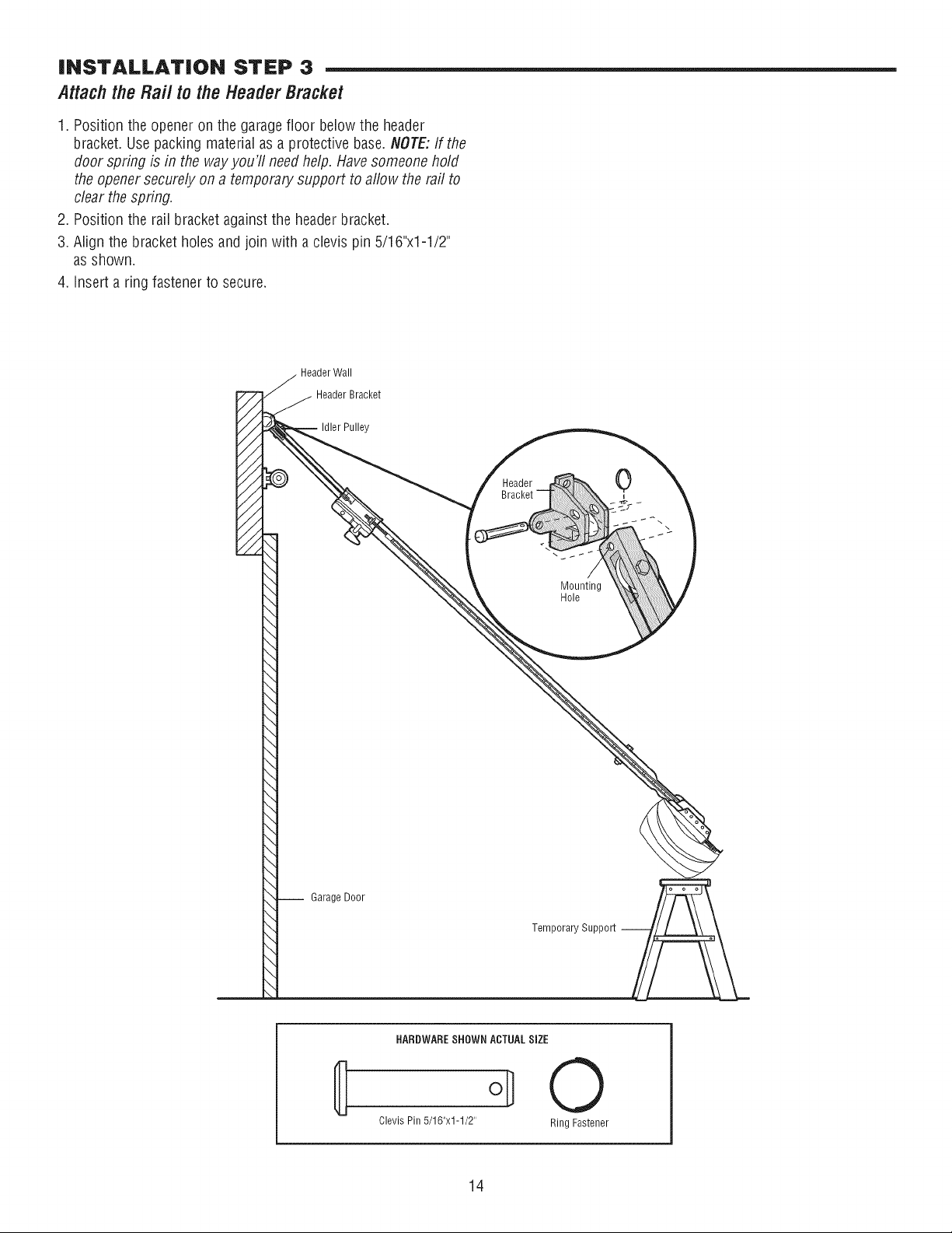
iNSTALLATiON STEP 3
Attach the Rail to the HeaderBracket
1. Position the opener on the garagefloor below the header
bracket. Use packing material as a protective base. NOTE:If the
door spring is in the way you'll needhelp. Havesomeone hold
the opener securely on a temporary support to aflow the raft to
clear the spring.
2. Position the rail bracket againstthe header bracket.
3. Align the bracket holes and join with a clevis pin 5/16"x1-1/2"
as shown.
4. Insert a ring fastener to secure.
HeaderBracket
Pulley
Header
Mounting
Hole
-- Garage Door
Temporary Support --
HARDWARESHOWN ACTUALSIZE
ol] 0
Clevis Pin5/16"x1-1/2" RingFastener
14
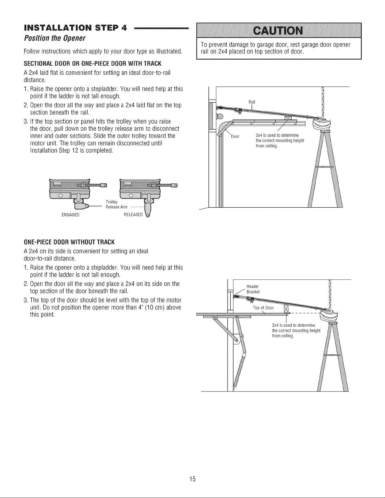
INSTALLATION STEP 4
Positionthe Opener
Follow instructions which apply to your door type as illustrated.
SECTIONALDOOROR ONE-PIECEDOORWITH TRACK
A 2x4 laid fiat is convenient for setting an idealdoor-to-rail
distance.
1. Raisethe opener onto a stepladder. You will need help at this
point if the ladderis not tall enough.
2. Openthe door all the way and place a 2x4 laidfiat on the top
section beneaththe rail.
3. If the top section or panel hits the trolley when you raise
the door, pull down on the trolley releasearm to disconnect
innerand outer sections. Slide the outer trolley toward the
motor unit. The trolley can remain disconnecteduntil
installationStep 12 is completed.
ENGAGED
To prevent damageto garage door, rest garagedoor opener
rail on 2x4 placed on top section of door.
Rail
ONE-PIECEDOORWITHOUTTRACK
A 2x4 on its side is convenient for setting an ideal
door-to-rail distance.
1. Raisethe opener onto a stepladder. You will need help at this
point if the ladder is not tall enough.
2. Openthe door aii the way and place a 2x4 on its side on the
top section of the door beneaththe rail.
3. The top of the door should be level with the top of the motor
unit. Do not position the opener more than 4" (10 cm) above
this point.
Header
Bracket
the correct mounting height
from ceiling.
15
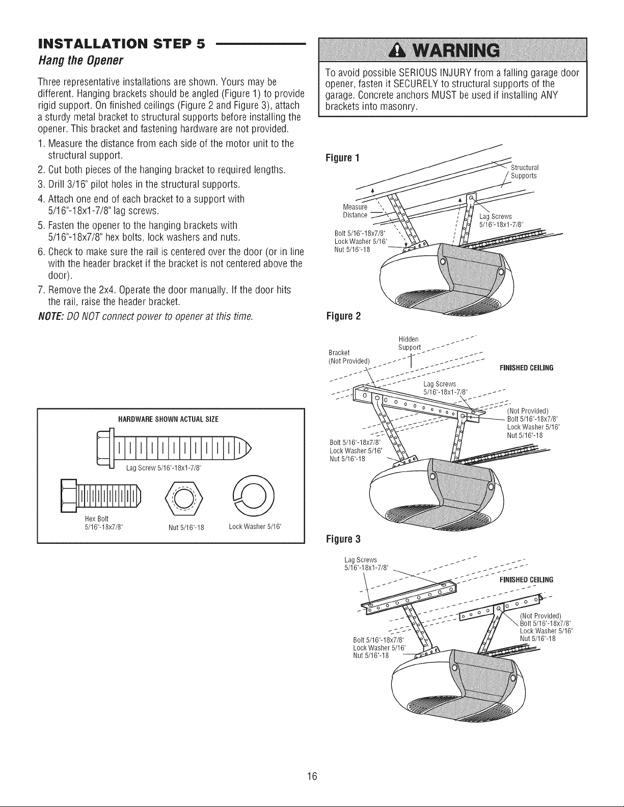
INSTALLATION STEP 5
Hang the Opener
Three representativeinstallations are shown. Yours may be
different. Hanging brackets should be angled (Figure 1) to provide
rigid support. Onfinished ceilings (Figure 2 and Figure 3), attach
a sturdy metal bracket to structural supports before installing the
opener. This bracket and fastening hardware are not provided.
1. Measurethe distance from each side of the motor unit to the
structural support.
2. Cut both pieces of the hanging bracket to required lengths.
3. Drill 3/16" pilot holes in the structural supports.
4. Attach one end of each bracket to a support with
5/16"-18xl -7/8" lag screws.
5. Fastenthe opener to the hanging brackets with
5/16"-18x7/8" hex bolts, lock washers and nuts.
6. Checkto make sure the rail is centered over the door (or in line
with the header bracket if the bracket is not centeredabove the
door).
7. Removethe 2x4. Operatethe door manually. If the door hits
the rail, raise the header bracket.
NOTE:DO NOTconnect power to opener at this time.
To avoid possible SERIOUSINJURYfrom afalling garage door
opener, fasten it SECURELYto structural supports of the
garage. Concrete anchors MUST be used if installing ANY
brackets into masonry.
Figure 1
Supports
Measure ',
Distance
Bolt 5/16"-18x7/8"
Lock Washer 5/16"
Nut 5/16"-18
LagScrews
5/16"-18xl-7/8"
Figure 2
Bracket
Hidden ..--*
Support .-_
HARDWARE SHOWN ACTUALSiZE
D D@
Hex Bolt
5/16"-18x7/8" Nut 5/16"-18 LockWasher 5/16"
Figure 3
Lag Screws
5/16"-18xl -7/8"
Bolt 5/16"-18x7/8"
Lock Washer 5/16"
Nut 5/16"-18
(Not Provided)
Bolt 5/16"-18x7/8"
Lock Washer 5/16"
Nut 5/16"-18
16
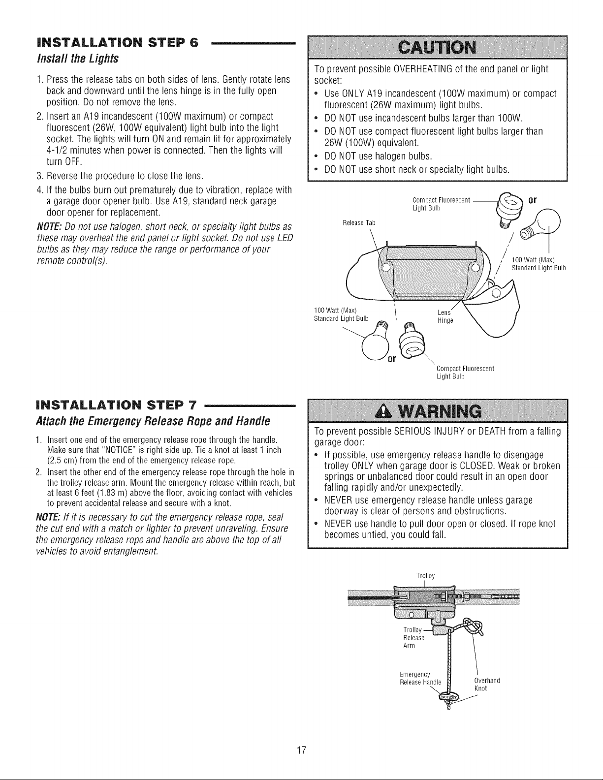
iNSTALLATiON STEP 6
install the Lights
1. Pressthe releasetabs on both sides of lens. Gentlyrotate lens
back and downward until the lens hinge is in the fully open
position. Do not removethe lens.
2. Insert an A19 incandescent (lOOW maximum) or compact
fluorescent (26W, IOOWequivalent) light bulb into the light
socket. The lights will turn ONand remain lit for approximately
4-1/2 minutes when power is connected.Then the lights will
turn OFF.
3. Reversethe procedure to close the lens.
4. If the bulbs burn out prematurely due to vibration, replacewith
a garage door opener bulb. UseA19, standard neck garage
door opener for replacement.
NOTE:Do not use halogen, short neck, or specialty light bulbs as
these may overheatthe end panel or light socket. Do not use LED
bulbs as they may reduce the range or performance of your
remote control(s).
To prevent possible OVERHEATINGof the end panel or light
socket:
* UseONLYA19 incandescent(IOOW maximum) or compact
fluorescent (26W maximum) light bulbs.
* DONOTuse incandescent bulbs larger than IOOW.
* DONOTuse compact fluorescent light bulbs larger than
26W (IOOW) equivalent.
* DONOTuse halogen bulbs.
* DONOTuse short neck or specialty light bulbs.
Release Tab
Compact Fluorescent --
Light Bulb
,/ 100Watt(Max)
Standard Light Bulb
!
100Watt(Max) \
Standard Light Bulb _
Hinge
Compact Fluorescent
Light Bulb
iNSTALLATiON STEP 7
Attach the EmergencyRelease Rope and Handle
1. Insertoneendof the emergencyreleaseropethroughthe handle.
Makesurethat"NOTICE"is right sideup.Tiea knotat least1 inch
(2.5 cm)from the endof the emergencyreleaserope.
2. insertthe otherend of the emergencyreleaseropethroughthe holein
the trolleyreleasearm. Mountthe emergencyreleasewithinreach,but
at least6feet (1.83 m) abovethefloor, avoidingcontactwithvehicles
to preventaccidentalreleaseand securewith a knot.
NOTE:If it is necessary to cut the emergency release rope, seal
the cut end with a match or lighter to prevent unraveling. Ensure
the emergency release rope and handle are above the top of aft
vehicles to avoid entanglement.
To prevent possible SERIOUSINJURYor DEATHfrom a falling
garage door:
* If possible, use emergency release handle to disengage
trolley ONLYwhen garage door is CLOSED.Weak or broken
springs or unbalanced door could result in an open door
falling rapidly and/or unexpectedly.
* NEVERuse emergency release handle unless garage
doorway is clear of persons and obstructions.
* NEVERuse handle to pull door open or closed. If rope knot
becomes untied, you could fall.
Trolley
Trolle
Release
Arm
Emergency
Release Handle
Overhand
Knot
17
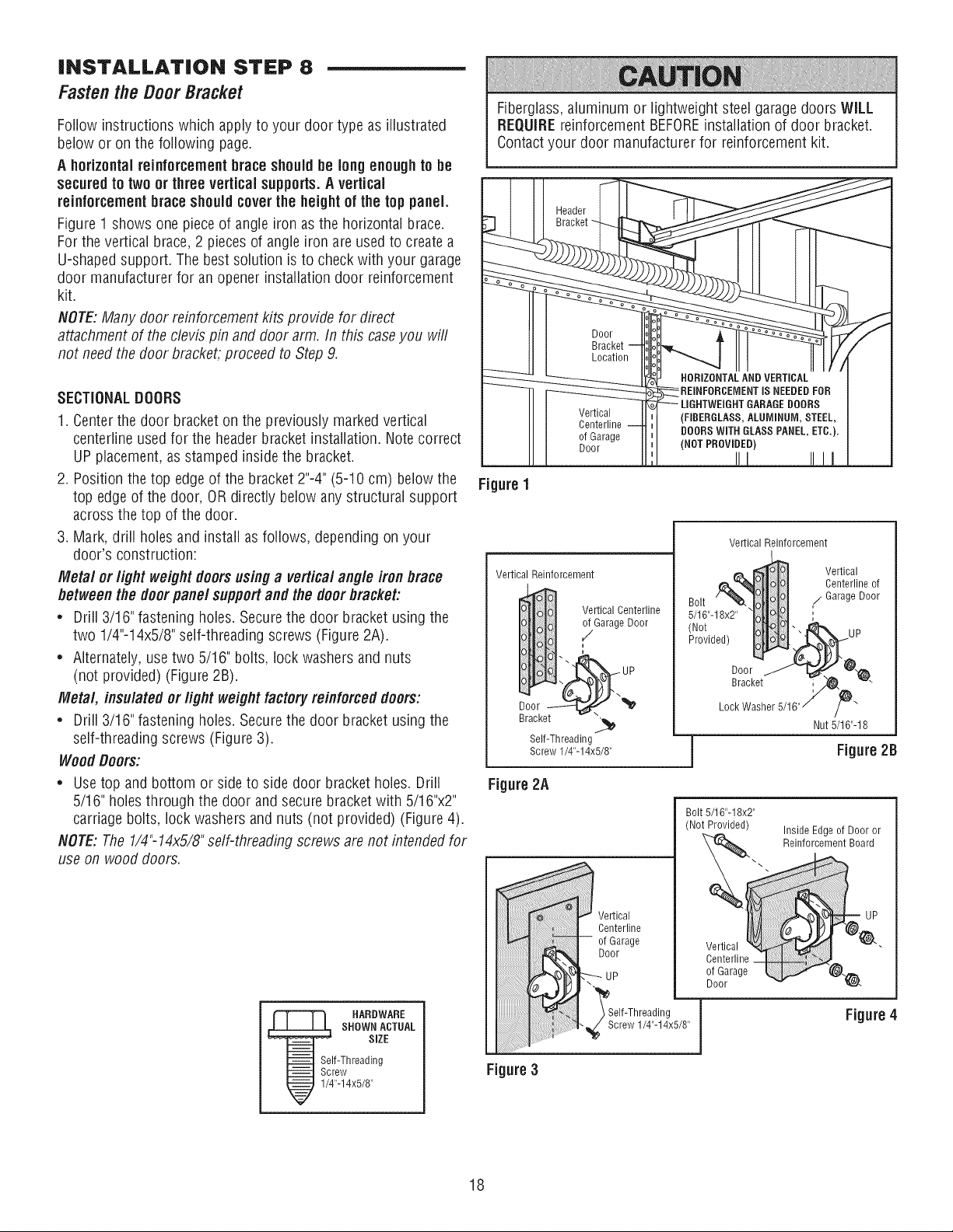
iNSTALLATiON STEP 8
Fastenthe Door Bracket
Follow instructions which apply to your door type as illustrated
below or on the following page.
A horizontalreinforcementbrace should be long enough to be
secured to two or three vertical supports.A vertical
reinforcement braceshouldcover the height of the top panel
Figure 1 shows one piece of angle iron as the horizontal brace.
For the vertical brace,2 pieces of angle iron are used to create a
U-shapedsupport. The best solution is to check with your garage
door manufacturer for an opener installation door reinforcement
kit.
NOTE:Many door reinforcement kits provide for direct
attachment of the clevis pin and door arm. In this case you will
not needthe door bracket, proceed to Step 9.
SECTIONALDOORS
1. Centerthe door bracket on the previously marked vertical
centerline used for the header bracket installation. Note correct
UP placement, as stamped inside the bracket.
2. Position the top edge of the bracket 2"-4" (5-10 cm) below the
top edge of the door, OR directly below any structural support
across the top of the door.
3. Mark, drift holes and install as follows, depending on your
door's construction:
Metal or light weight doorsusing a vertical angle iron brace
betweenthe doorpanel support andthe doorbracket:
* Drill 3/16" fastening holes. Secure the door bracket using the
two 1/4"-14x5/8" self-threading screws (Figure 2A).
* Alternately, use two 5/16" bolts, lock washers and nuts
(not provided) (Figure 2B).
Metal, insulated or light weight factoryreinforced doors:
* Drill 3/16" fastening holes. Secure the door bracket using the
self-threading screws (Figure 3).
Wood Doors:
* Usetop and bottom or side to side door bracket holes. Drill
5/16" holes through the door and secure bracket with 5/16"x2"
carriage bolts, lock washers and nuts (not provided) (Figure 4).
NOTE:The 1/4"-14x5/8"self-threading screws are not intended for
use on wood doors.
HARDWARE
SHOWN ACTUAL
SiZE
If-Threading
rew
"-14x5/8"
Fiberglass,aluminum or lightweight steel garagedoors WiLL
REQUIREreinforcement BEFOREinstallation of door bracket.
Contactyour door manufacturer for reinforcement kit.
Vertical
Centerline
of Garage
Door
Figure 1
Vertical Reinforcement
Vertical Centerline
of Garage Door
/
i
Door_ "_
Bracket _}_
Self-Threading
Screw 1/4"-14x5/8"
Figure 2A
Vertical Reinforcement
Vertical
Centerline of
Bolt ,/Garage Door
5/16"-18x ',
'r°tv e0,
Lock Washer 5/16 ''/_I _\
Nut 5/16"-18
I Figure 2B
Vertical
Centerline
of Garage
Door
\
_Self-Threading
_j_ Screw 1/4"-14x5/8' j
Bolt 5/16"-18x2"
(Not Provided)
Inside Edge of Door or
Reinforcement Board
Vertical
Centerline
of Garage
Door
Figure 4
Figure 3
18
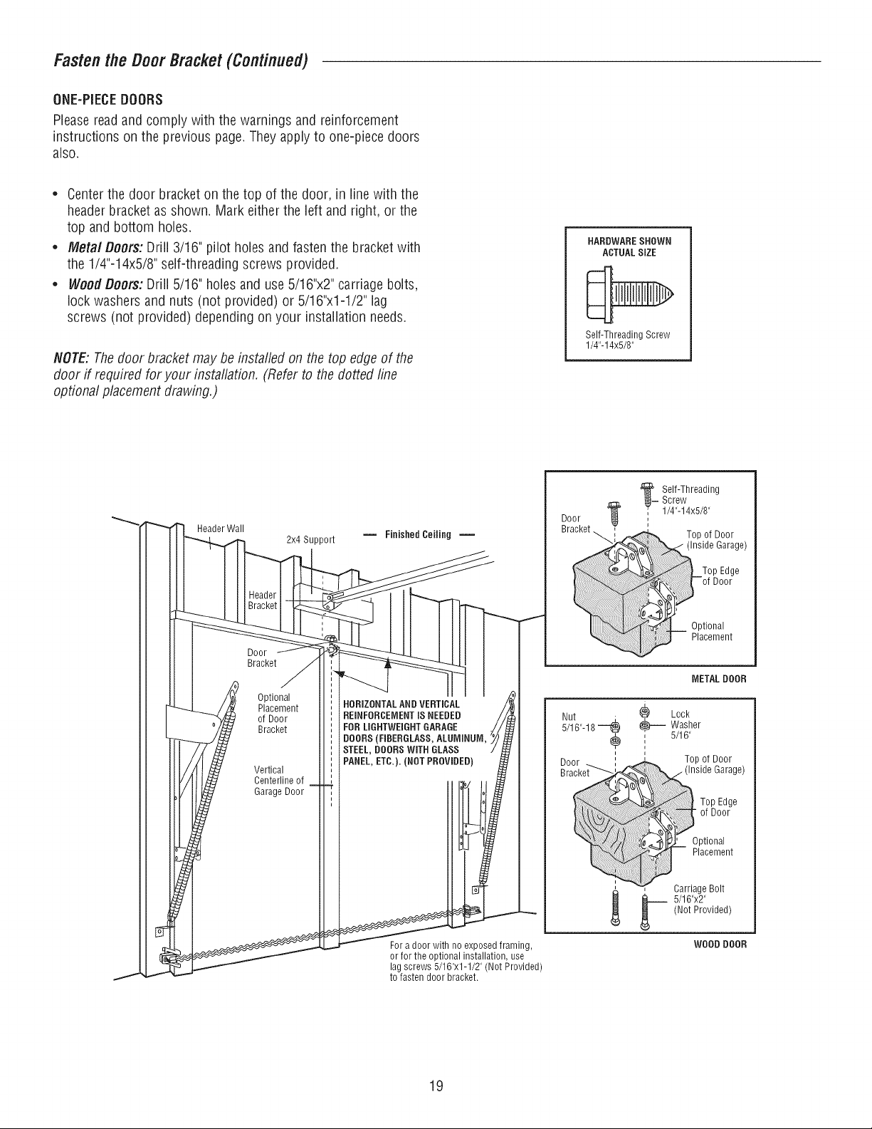
Fastenthe Door Bracket(Continued)
ONE-PIECEDOORS
Please readand comply with the warnings and reinforcement
instructions on the previous page. They apply to one-piece doors
also.
* Centerthe door bracket on the top of the door, in line with the
header bracket as shown. Mark either the left and right, or the
top and bottom holes.
* Meta/Doors: Drill 3/16" pilot holes and fasten the bracket with
the 1/4"-14x5/8" self-threading screws provided.
* WoodDoors:Drift 5/16" holes and use 5/16"x2" carriage bolts,
lock washers and nuts (not provided) or 5/16"x1-1/2" lag
screws (not provided) depending on your installation needs.
NOTE:Thedoor bracket may be installed on the top edge of the
door if required for your installation. (Referto the dotted line
optional placement drawing.)
HARDWARESHOWN
ACTUAL SIZE
Self-Threading Screw
1/4"-14x5/8"
Header Wall
Door
Bracket
2x4 Support
Optional
Placement
of Door
Bracket
Vertical
Centerline of
Garage Door
HORIZONTALAND VERTICAL
REINFORCEMENTIS NEEDED
FOR LIGHTWEIGHTGARAGE
DOORS(FIBERGLASS,ALUMINUM,
STEEL, DOORSWITH GLASS
PANEL, ETC.). (NOT PROVIDED)
For a door with no exposed framing,
or for the optional installation, use
lag screws 5/16"x1-1/2" (Not Provided)
to fasten door bracket.
_Self-Threading
Screw
" 1/4"-14x5/8"
Door
Bracket_
' _nside Garage)
........................................................... °o"0e
;;iil;il;!i:iiiiiiiiiiiiiiiiii_ii!:!!ii:ii_iii!i:!iii_!!_'
t_onal
Placement
METAL DOOR
Nut _ Lock
SJtB'-fB---¢¢-- Washer
, 5/16"
i
i
i
Door
Bracket_
_-- 5/16"x2"
(Not Provided)
WOOD DOOR
19
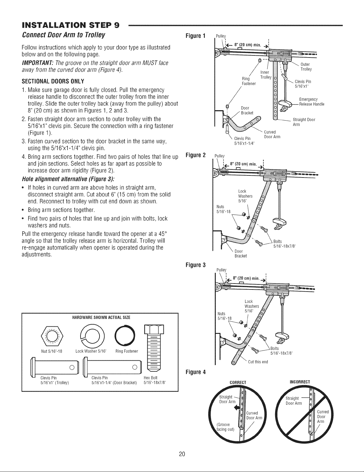
INSTALLATION STEP 9
ConnectDoor Arm to Trolley
Follow instructions which apply to your door type as illustrated
below and on the following page.
/MPORTAHT:Thegroove on the straight door arm MUST face
away from the curved door arm (Figure 4).
SECTIONALDOORSONLY
1. Makesure garage door is fully closed. Pull the emergency
releasehandle to disconnect the outer trolley from the inner
trolley. Slide the outer trolley back (away from the pulley) about
8" (20 cm) as shown in Figures 1,2 and 3.
2. Fastenstraight door arm section to outer trolley with the
5/16"x1"clevis pin. Secure the connection with a ring fastener
(Figure 1).
3. Fastencurved section to the door bracket in the same way,
using the 5/16"x1-1/4" clevis pin.
4. Bring arm sections together. Find two pairs of holes that line up
andjoin sections. Select holes as far apart as possible to
increasedoor arm rigidity (Figure 2).
Hole alignment alternative (Figure 3):
,' If holes in curved arm are above holes in straight arm,
disconnect straight arm. Cut about 6" (15 cm) from the solid
end. Reconnectto trolley with cut end down as shown.
* Bring arm sections together.
* Find two pairs of holes that line up and join with bolts, lock
washers and nuts.
Pull the emergency releasehandle toward the opener at a 45°
angle so that the trolley releasearm is horizontal. Trolley will
re-engageautomatically when opener is operated during the
adjustments.
HARDWARESHOWN ACTUALSiZE
©
LockWasher 5/16" Ring Fastener
Clevis Pin Clevis Pin
5/16"x1" (Trolley) 5/16"x1-1/4" (Door Bracket)
@
Nut 5/16"-18
Hex Bolt
5/16"-18x7/8"
Figure 1
Figure 2
Figure 3
Figure 4
Pulley
_.- 8" (20 cm) rain..__,,
Ring
Fastener
O4oor
Bracket
Curved
Clevis Pin Door Arm
5/16"x1-1/4"
Pulley
\ i-8"(2o°m) i
Lock /
Washers /o_
5/16" /o/
Nuts \ £7
5/16"-1B
%-
Bracket
_ Bolts
5/16"-18x7/8"
Outer
Trolley
Clevis Pin
5/16"xl"
Emergency
Handle
Straight Door
Arm
_luts
5/16"-18
Lock
Washers
5/16"
XBolts
5/16"-18x7/8"
Cut this end
CORRECT
iNCORRECT
2O
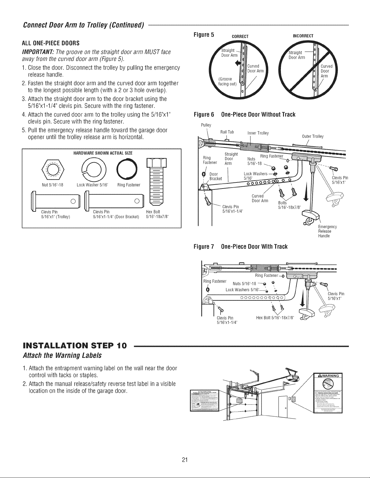
ConnectDoorArm to Tro//ey(Continued)
ALL0NE-PIECEDOORS
IMPORTANT:Thegroove on the straight door arm MUST face
away from the curved door arm (Figure 5).
1. Closethe door, Disconnect the trolley by pulling the emergency
releasehandle,
2. Fastenthe straight door arm and the curved door arm together
to the longest possible length (with a 2 or 3 hole overlap),
3. Attach the straight door arm to the door bracket using the
5/16"x1-1/4" clevis pin. Secure with the ring fastener.
4. Attach the curved door arm to the trolley using the 5/16"x1"
clevis pin. Secure with the ring fastener,
5. Puii the emergency release handletoward the garagedoor
opener until the trolley releasearm is horizontal.
Nut 5/16"-18
HARDWARESHOWN ACTUALSiZE
©
Lock Washer 5/16" Ring Fastener
Clevis Pin Clevis Pin
5/16"x1" (Trolley) 5/16"x1-1/4" (Door Bracket)
Hex B01t
5/16"-1 8x7/8"
Figure 5
Figure6
Pulley
Ring
Fastener
_/ Door
Figure 7
CORRECT
iNCORRECT
0he-Piece BoorWithout Track
RailTab Inner Trolley
Outer Trolley
Straight Ring Fastener
Door Nuts
Arm 5/16"-18 _@
Lock Washers --_
5/16"
Pin
5/16"x1-1/4"
Curved
Door Arm
Bolts
5/16"-18x7/8"
0he-Piece BoorWith Track
Emergency
Release
Handle
Clevis Pin
5/16"x1"
Ring Fastener--o-
Ring Fastener Nuts 5/16"-18 --Q Q / /
L0ckWashers5/16'_'&, 'o J /
_._ ooooooo_o_oiLJ
_J"il_evls Pin Hex B01t15/16_.18x7/8 i
5/16"x1-1/4"
iNSTALLATiON STEP 10
Attachthe Warning Labe/s
1. Attach the entrapment warning label on the wall nearthe door
control with tacks or staples.
2. Attach the manual release/safetyreverse test label in a visible
location on the inside of the garagedoor.
21
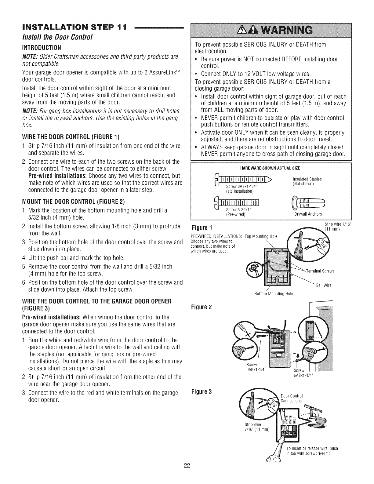
INSTALLATION STEP 11
InstalltheDoorContro/
iNTRODUCTiON
NOTE: OlderCraftsman accessories and third party products are
not compatible.
Your garage door opener is compatible with up to 2 AssureLinkTM
door controls.
Install the door control within sight of the door at a minimum
height of 5 feet (1.5 m) where small children cannot reach,and
away from the moving parts of the door.
NOTE:For gang box installations it is not necessaryto drill holes
or install the drywall anchors. Usethe existing holes in the gang
box.
WiRETHE DOORCONTROL(FIGURE1)
1. Strip 7/16 inch (11 mm) of insulation from one end of the wire
and separate the wires.
2. Connect one wire to each of the two screws on the back of the
door control. The wires can be connected to either screw.
Pre-wired installations:Choose any two wires to connect, but
make note of which wires are used so that the correct wires are
connected to the garage door opener in a later step.
MOUNTTHEDOORCONTROL(FIGURE2)
1. Mark the location of the bottom mounting hole and drill a
5/32 inch (4 mm) hole.
2. install the bottom screw, allowing 1/8 inch (3 mm) to protrude
from the wail.
3. Position the bottom hole of the door control over the screw and
slide down into place.
4. Lift the push bar and mark the top hole.
5. Removethe door control from the wall and drill a 5/32 inch
(4 mm) hole for the top screw.
6. Position the bottom hole of the door control over the screw and
slide down intoplace. Attach the top screw.
WiRE THE DOORCONTROLTOTHE GARAGEDOOROPENER
(FIGURE3)
Pre-wired installations: When wiring the door control to the
garagedoor opener makesure you use the same wires that are
connected to the door control.
1. Run the white and red/white wire from the door control to the
garagedoor opener. Attach the wire to the wall and ceiling with
the staples (not applicable for gang box or pre-wired
installations). Do not piercethe wire with the staple as this may
cause a short or an open circuit.
2. Strip 7/16 inch (11 mm) of insulation from the other end of the
wire nearthe garage door opener.
3. Connect the wire to the red and white terminals on the garage
door opener.
To prevent possible SERIOUSINJURYor DEATHfrom
electrocution:
* Be sure power is NOT connected BEFOREinstalling door
control.
* Connect ONLYto 12 VOLT low voltage wires.
To prevent possible SERIOUSINJURYor DEATHfrom a
closing garage door:
* install door control within sight of garage door, out of reach
of children at a minimum height of 5 feet (1.5 m), and away
from ALL moving parts of door.
* NEVERpermit children to operate or play with door control
push buttons or remote control transmitters.
* Activate door ONLYwhen it can be seen clearly, is properly
adjusted, and there are no obstructions to door travel.
* ALWAYSkeep garage door in sight until completely closed.
NEVERpermit anyone to cross path of closing garage door.
HARDWARESHOWN ACTUAL SiZE
(std installation)
(Pre-wired)
Insulated Staples
(Not shown)
Drywall Anchors
Figure1
PRE-WIRED INSTALLATIONS: Top Mounting Hole
Choose any two wires to \
connect, but make note of
which wires are used.
Strip wire 7/16"
(11 mm)
Figure2
Bell Wire
Bottom Mounting Hole
6ABxl-1/4" Screw m
6ABx1-1/4"
Figure3
Door Control
Connections
Stripwire
7/16"(11 mm)
To insert or release wire, push
in tab with screwdriver tip
22
iNSTALLATiON STEP 1 2
Install TheProtectorSystem®
iMPORTANTiNFORMATiONABOUTTHESAFETYREVERSING
SENSOR
The safety reversingsensormust be connectedand aligned
correctlybeforethegaragedooropenerwill moveinthedown
direction.
The sending sensor (with an amber LED)transmits an invisible
light beam to the receiving sensor (with a green LED). If an
obstruction breaksthe light beam while the door is closing, the
door will stop and reverseto the full open position, and the
garagedoor opener lights will flash 10 times.
NOTE:For energy efficiency the garage door opener will enter
sleep mode when the door is fully closed. Thesleep mode shuts
the garagedoor opener down until activated. Thesleep mode is
sequenced with the garage door opener light bulb, as the light bulb
turns off the sensor LEDs will turn off and whenever the garage
door opener lights turn on the sensor LEDs will light. Thegarage
door opener will not go into the sleep mode until the garagedoor
opener has completed 5 cycles upon power up.
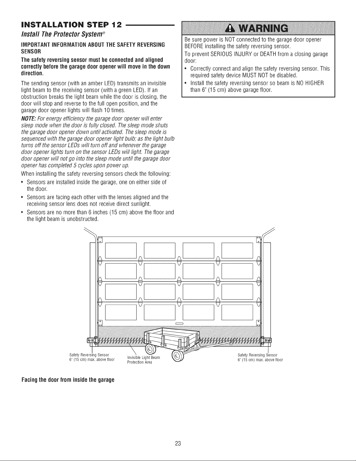
When installing the safety reversing sensors check the following:
• Sensors are installed inside the garage,one on either side of
the door.
• Sensors are facing each other with the lensesaligned and the
receivingsensor lens does not receive direct sunlight.
• Sensors are no more than 6 inches (15 cm) above the floor and
the light beam is unobstructed.
Besure power is NOTconnected to the garage door opener
BEFOREinstalling the safety reversing sensor.
To prevent SERIOUSINJURY or DEATHfrom a closing garage
door:
• Correctly connect and align the safety reversing sensor. This
required safety device MUST NOT be disabled.
• install the safety reversing sensor so beam is NO HIGHER
than 6" (15 cm) above garage floor.
Safety Reversing Sensor
6" (15 cm) max. above floor
Invisible Light Beam
Protection Area
Safety Reversing Sensor
6" (15 cm) max. above floor
Facing the door from inside the garage
23
/nsta// TheProtectorSystem®(Continued)
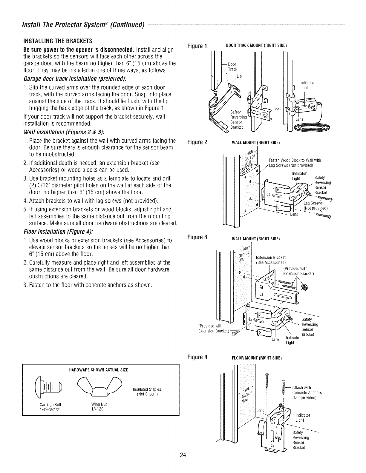
iNSTALLiNGTHE BRACKETS
Be sure power to the opener is disconnected. Install and align
the brackets so the sensors will face each other across the
garagedoor, with the beam no higher than 6" (15 cm) above the
floor. They may be installedin one of three ways, as follows.
Garage doortrack installation (preferred):
1. Slip the curved arms over the rounded edge of each door
track, with the curved arms facing the door. Snap into place
against the side of the track. It should lie flush, with the lip
hugging the back edgeof the track, as shown in Figure 1.
if your door track will not support the bracket securely, wall
installation is recommended.
Waft installation (Figures2 & 3):
1. Placethe bracket against the wall with curved arms facing the
door. Besure there is enough clearancefor the sensor beam
to be unobstructed.
2. If additional depth is needed,an extension bracket (see
Accessories) or wood blocks can be used.
3. Use bracket mounting holes as a template to locate and drill
(2) 3/16" diameter pilot holes on the wall at each side of the
door, no higher than 6" (15 cm) above the floor.
4. Attach bracketsto wall with lag screws (not provided).
5. If using extension brackets or wood blocks, adjust right and
left assemblies to the same distance out from the mounting
surface. Make sure all door hardware obstructions are cleared.
Floor installation (Figure 4):
1. Usewood blocks or extension brackets (see Accessories) to
elevatesensor brackets so the lenseswill be no higher than
6" (15 cm) above the floor.
2. Carefully measure and place right and left assemblies at the
same distance out from the wall. Be sure all door hardware
obstructions are cleared.
3. Fastento the floor with concrete anchors as shown.
Figure 1
Figure2
Figure3
DOORTRACK MOUNT (RIGHT SIDE)
Track
Lip
WALL MOUNT (RIGHT SIDE)
Indicator
Light
FastenWood Block to Wall with
(Not provided)
Indicator
Light Safety
Reversing
Sensor
Bracket
Lag Screws
-. (Not provided)
Lens ...... _@
WALL MOUNT (RIGHT SIDE)
Extension Bracket
See Accessories)
(Provided with
Extension Bracket)
Carriage Bolt
1/4"-20xl/2"
HARDWARESHOWN ACTUAL SIZE
Wing Nut
1/4"-20
InsulatedStaples
(NotShown)
(Provided with
Extension Bracket) _'"
k_
Lens
Figure4
FLOORMOUNT (RIGHT SIDE)
24
Safety
Reversing
Sensor
Bracket
Indicator
Light
-- ttach with
Concrete Anchors
; (Not provided)
Light
Safety
Reversing
Sensor
Bracket
/nsta// TheProtectorSystem®(Continued)
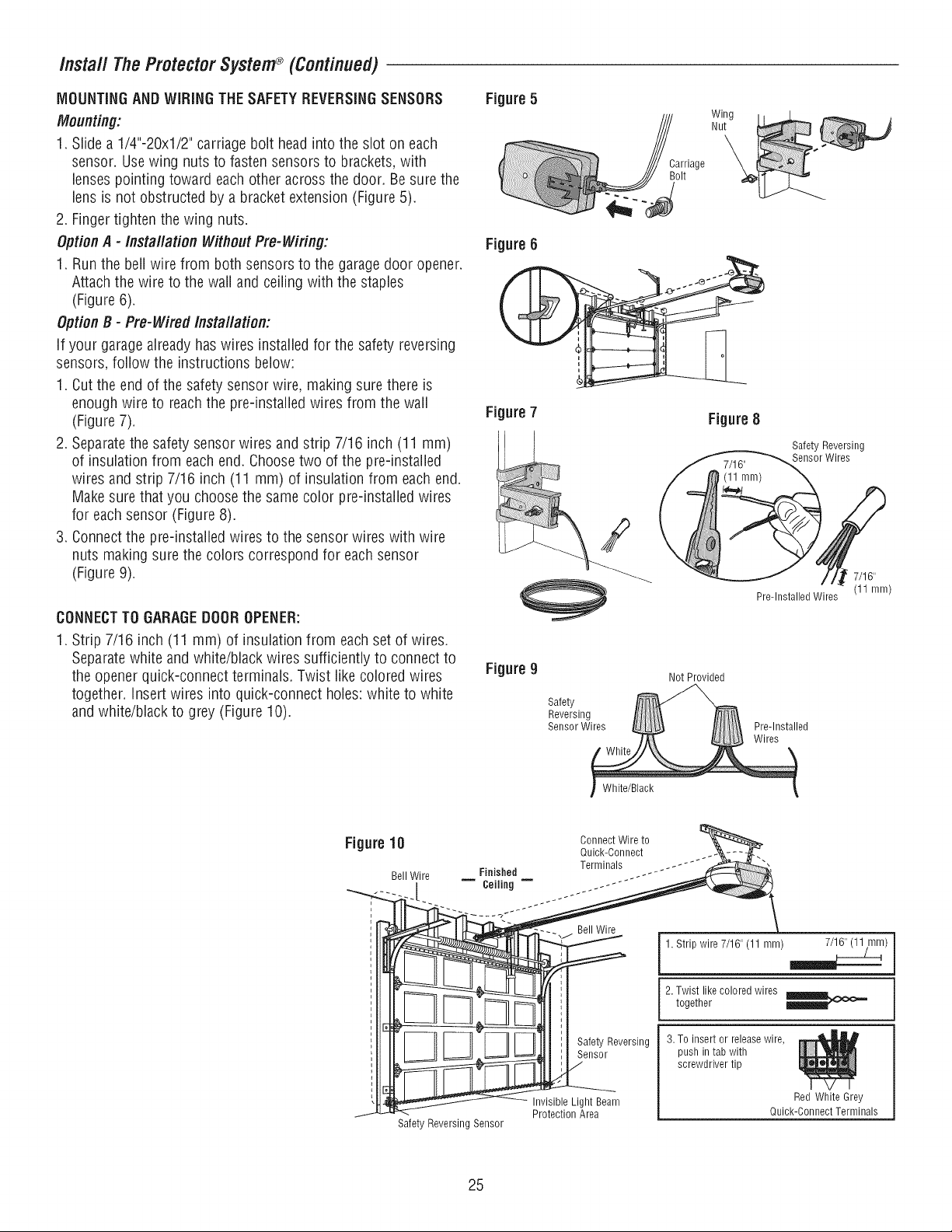
MOUNTINGANDWiRiNG THESAFETYREVERSINGSENSORS
Mounting:
1. Slide a 1/4"-20xl/2" carriage bolt headinto the slot on each
sensor. Usewing nuts to fasten sensors to brackets, with
lenses pointing toward each other across the door. Besure the
lens is not obstructed by a bracket extension (Figure 5).
2. Finger tighten the wing nuts.
Option A -/nsta//ation WithoutPre-Wiring:
1. Run the bell wire from both sensors to the garage door opener.
Attach the wire to the wall and ceiling with the staples
(Figure 6).
Option B - Pre-Wired /nsta//ation:
If your garage already has wires installed for the safety reversing
sensors, follow the instructions below:
1. Cut the end of the safety sensor wire, making sure there is
enough wire to reachthe pre-installed wires from the wall
(Figure 7).
2. Separatethe safety sensor wires and strip 7/16 inch (11 mm)
of insulation from each end. Choosetwo of the pre-instailed
wires and strip 7/16 inch (11 mm) of insulation from each end.
Make sure that you choose the same color pre-installed wires
for each sensor (Figure 8).
3. Connect the pre-installed wires to the sensor wires with wire
nuts making sure the colors correspond for each sensor
(Figure 9).
CONNECTTO GARAGEDOOROPENER:
1. Strip 7/16 inch (11 mm) of insulation from each set of wires.
Separatewhite and white/black wires sufficiently to connect to
the opener quick-connect terminals. Twist like colored wires
together, insert wires into quick-connect holes:white to white
and white/black to grey (Figure 10).
Figure 5
Carriage
Bolt
Figure 6
i
Figure7
Figure 8
Figure 9
Safety
Reversing
Sensor Wires
Not Provided
Safety Reversing
Sensor Wires
Pre-lnstalled Wires
Pre-lnstalled
Wires
7/16II
(11 mm)
White/Black
Figure10
Bell Wire
i
Safety Reversing Sensor
Connect Wire to
Quick-Connect
Terminals
Finished .. - - -
= Ceiling = jz--
Bell Wire
SafetyReversing
Sensor
Invisible Light Beam
Protection Area
1. Strip wire 7/16" (11 mm) _)
2. Twist like colored wires
together
3. To insert or release wire,
push in tab with
screwdriver tip
Red White Grey
Quick-Connect Terminals
25
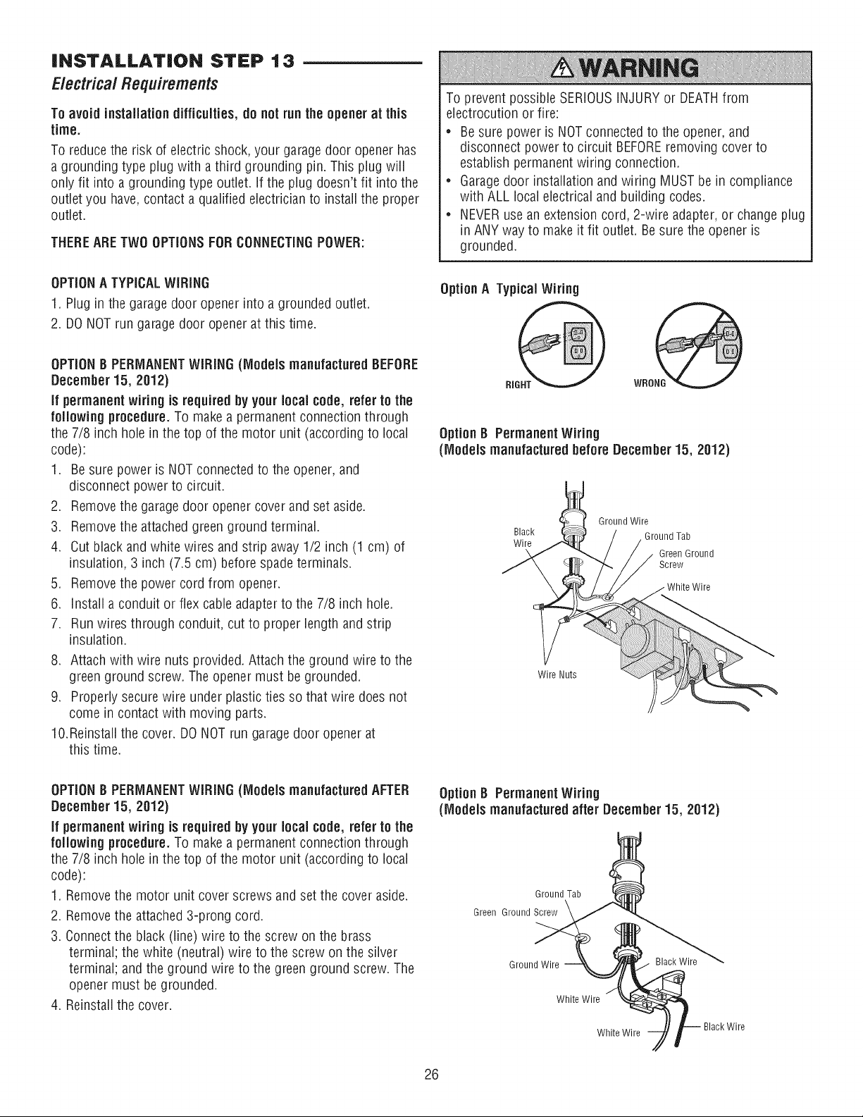
iNSTALLATiON STEP 13
Electrical Requirements
To avoid installation difficulties, do not run the opener at this
time.
To reduce the risk of electric shock, your garagedoor opener has
a grounding type plug with a third grounding pin. This plug will
only fit into a grounding type outlet. If the plug doesn't fit into the
outlet you have, contact a qualified electrician to install the proper
outlet.
THEREARETWO OPTIONSFOR CONNECTINGPOWER:
OPTIONA TYPICALWIRING
1. Plug in the garagedoor opener into a grounded outlet.
2. DONOT run garage door opener at this time.
OPTION8 PERMANENTWiRiNG (Models manufacturedBEFORE
December 15, 2012)
if permanent wiring is required by your local code, refer to the
following procedure.To makea permanentconnection through
the 7/8 inch hole in the top of the motor unit (according to local
code):
1. Be sure power is NOTconnected to the opener, and
disconnect power to circuit.
2. Remove the garagedoor opener cover and set aside.
3. Remove the attached green ground terminal.
4. Cut black andwhite wires and strip away 1/2 inch (1 cm) of
insulation, 3 inch (7.5 cm) before spade terminals.
5. Remove the power cord from opener.
6. installa conduit or flex cable adapter to the 7/8 inch hole.
7. Run wires through conduit, cut to proper lengthand strip
insulation.
8. Attach with wire nuts provided. Attach the ground wire to the
green ground screw. The opener must be grounded.
9. Properly secure wire under plastic ties so that wire does not
come in contact with moving parts.
10.Reinstall the cover. DO NOTrun garagedoor opener at
this time.
To prevent possible SERIOUSINJURY or DEATHfrom
electrocution or fire:
* Besure power is NOTconnected to the opener, and
disconnect power to circuit BEFOREremoving cover to
establish permanent wiring connection.
* Garagedoor installation and wiring MUST be in compliance
with ALL local electrical and building codes.
* NEVERuse an extension cord, 2-wire adapter,or change plug
in ANY way to make it fit outlet. Be sure the opener is
grounded.
Option A Typical Wiring
WRONG
Option B Permanent Wiring
(Models manufactured before December 15, 2012)
Ground Wire
Black Ground Tab
Wire
Green Ground
Screw
Wire Nuts
OPTION8 PERMANENTWiRiNG (ModeJs manufactured AFTER
December 15, 2012)
if permanent wiring is required by your local code, refer to the
following procedure.To makea permanentconnection through
the 7/8 inch hole in the top of the motor unit (according to local
code):
1. Removethe motor unit cover screws and set the cover aside.
2. Removethe attached 3-prong cord.
3. Connectthe black (line) wire to the screw on the brass
terminal; the white (neutral) wire to the screw on the silver
terminal; and the ground wire to the green ground screw. The
opener must be grounded.
4. Reinstall the cover.
Option B Permanent Wiring
(Models manufactured after December 15, 2012)
Ground Tab
Green Ground Screw
Ground Wire
Black Wire
White Wire
White Wire
Black Wire
26
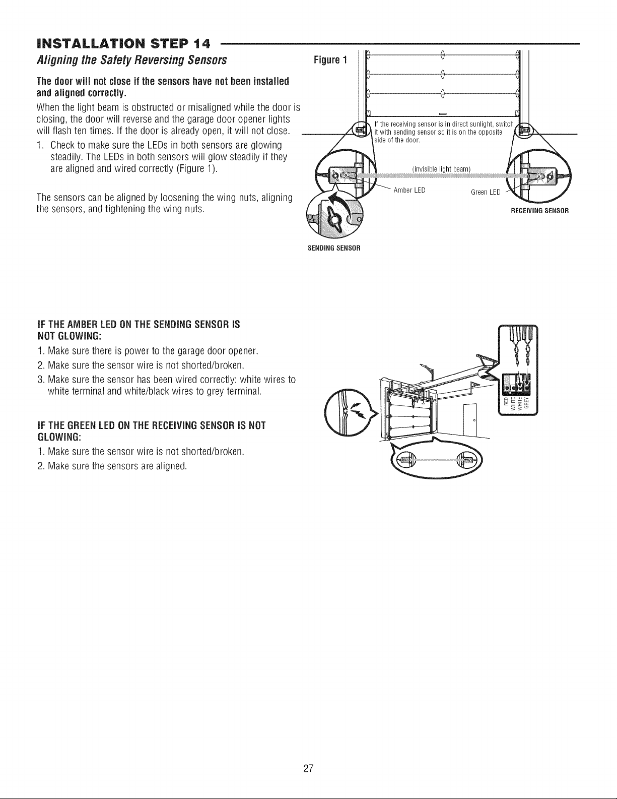
iNSTALLATiON STEP 14
Aligning the SafetyReversingSensors
The door wiil not close if the sensorshave not been installed
and aligned correctly.
When the light beam is obstructed or misaligned while the door is
closing, the door will reverseand the garagedoor opener lights
will flash ten times. If the door is already open, it will not close.
1. Checkto make sure the LEDs in both sensors are glowing
steadily. The LEDs in both sensors will glow steadily if they
are aligned and wired correctly (Figure 1).
The sensors can be aligned by loosening the wing nuts, aligning
the sensors, and tightening the wing nuts.
Figure 1
If the receiving sensor is in direct sunlight, switch
it with sending sensor so it is on the opposite
side of the door.
(invisible light beam)
Amber LED Green LED
1
RECEIVINGSENSOR
SENDINGSENSOR
IF THEAMBER LEDONTHE SENDINGSENSORIS
NOTGLOWING:
1. Makesure there is power to the garagedoor opener.
2. Makesure the sensor wire is not shorted/broken.
3. Makesure the sensor has been wired correctly: white wires to
white terminal and white/black wires to grey terminal.
iF THE GREENLEDONTHE RECEIVINGSENSORiS NOT
GLOWING:
1. Makesure the sensor wire is not shorted/broken.
2. Makesure the sensors are aligned.
27
ADJUSTMENT
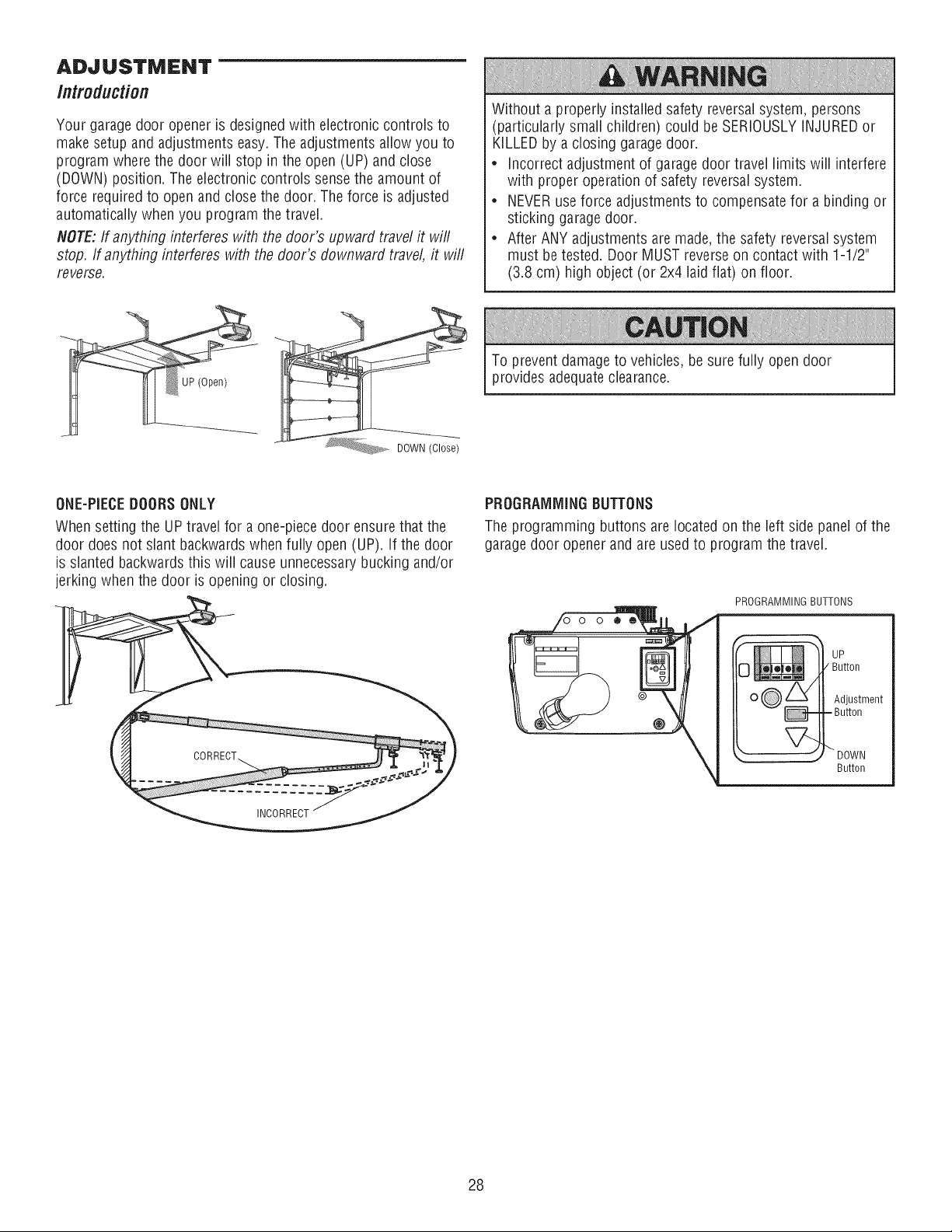
Introduction
Your garage door opener is designed with electronic controls to
make setup and adjustments easy.The adjustments allow you to
program where the door will stop in the open (UP) and close
(DOWN) position. The electronic controls sense the amount of
force required to open and close the door. The force is adjusted
automatically when you program the travel.
NOTE:If anything interferes with the door's upward travel it will
stop. If anything interferes with the door's downward travel, it will
reverse.
Without a properly installed safety reversalsystem, persons
(particularly small children) could be SERIOUSLYINJUREDor
KILLEDby a closing garagedoor.
• incorrect adjustment of garage door travel limits will interfere
with proper operation of safety reversal system.
• NEVERuse force adjustments to compensate for a binding or
sticking garage door.
• After ANY adjustments are made, the safety reversalsystem
must be tested. Door MUST reverse on contact with 1-1/2"
(3.8 cm) high object (or 2x4 laid fiat) on floor.
To prevent damage to vehicles, be sure fully open door
provides adequateclearance.
ONE-PIECEDOORSONLY
When setting the UP travel for a one-piece door ensure that the
door does not slant backwardswhen fully open (UP). If the door
is slanted backwards this will cause unnecessarybucking and/or
jerking when the door is opening or closing.
1
INCORRECT
PROGRAMMINGBUTTONS
The programming buttons are located on the left side panel of the
garagedoor opener and are used to program the travel.
PROGRAMMING BUTTONS
UP
/ Button
Adjustment
= Button
V--
"" DOWN
Button
28
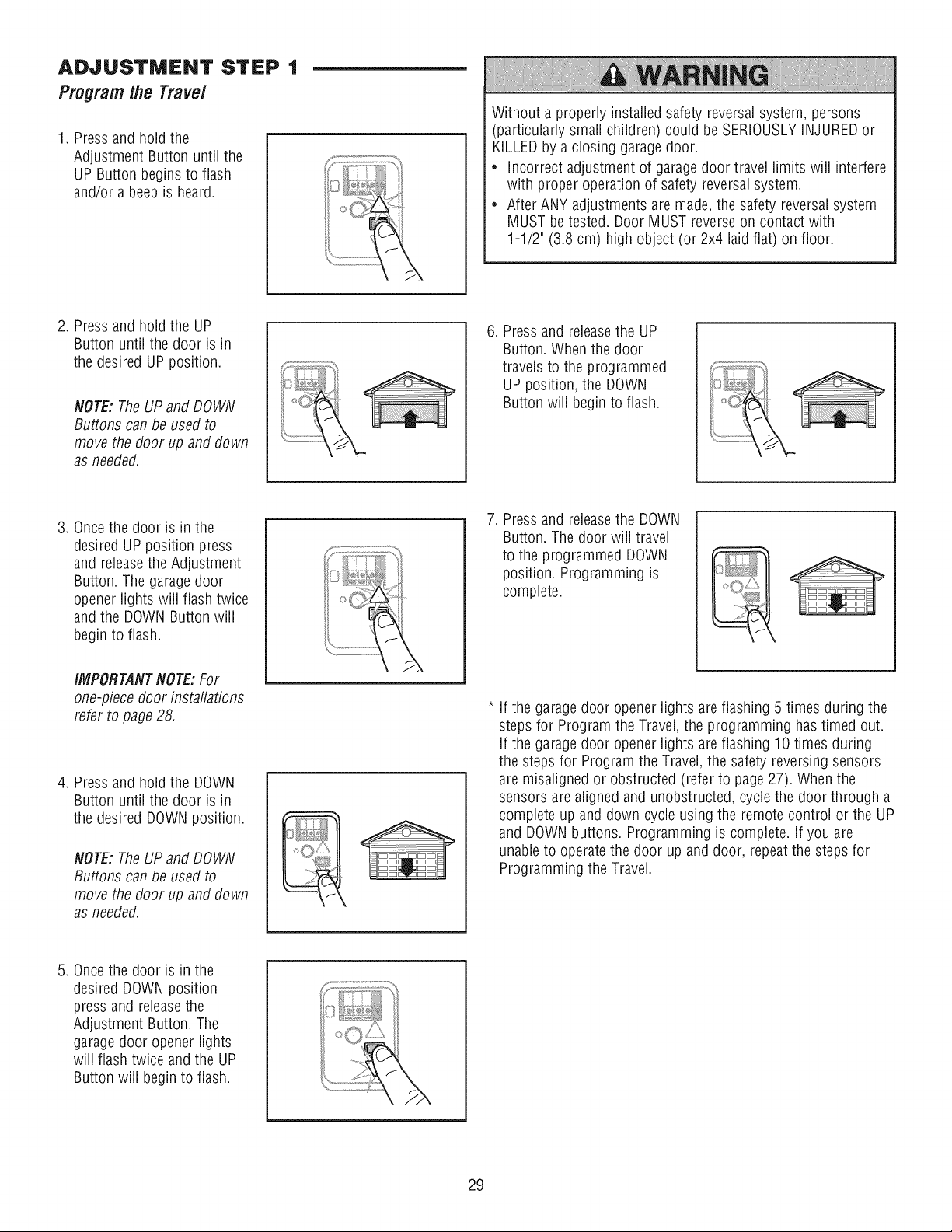
ADJUSTMENT STEP 1
Programlhe Trave/
1. Pressand hold the
Adjustment Button until the
UP Button begins to flash
and/or a beep is heard.
2. Pressand hold the UP
Button until the door is in
the desired UP position.
NOTE: The UPand DOWN
Buttons can be used to
move the door up and down
as needed.
3. Oncethe door is in the
desired UP position press
and releasethe Adjustment
Button. The garage door
opener lights will flash twice
and the DOWNButton will
beginto flash.
IMPORTANTNOTE:For
one-piece door installations
refer to page 28.
4. Pressand hold the DOWN
Button until the door is in
the desired DOWNposition.
NOTE: The UPand DOWN
Buttons can be used to
move the door up and down
as needed.
5. Oncethe door is in the
desired DOWNposition
press and releasethe
Adjustment Button. The
garagedoor opener lights
will flash twice and the UP
Button will begin to flash.
29
Without a properly installed safety reversalsystem, persons
(particularly small children) could be SERIOUSLYINJUREDor
KILLEDby a closing garage door.
* incorrect adjustment of garage door travel limits will interfere
with proper operation of safety reversal system.
* After ANY adjustments are made,the safety reversal system
MUST betested. Door MUST reverse on contact with
1-1/2" (3.8 cm) high object (or 2x4 laid fiat) on floor.
6. Pressand releasethe UP
Button. When the door
travels to the programmed
UP position, the DOWN
Button will begin to flash.
7. Pressand releasethe DOWN
Button. The door will travel
to the programmed DOWN
position. Programming is
complete.
If the garage door opener lights areflashing 5 times during the
steps for Program the Travel, the programming has timed out.
If the garage door opener lights areflashing 10 times during
the steps for Program the Travel, the safety reversing sensors
are misaligned or obstructed (refer to page 27). When the
sensors are aligned and unobstructed, cycle the door through a
complete up and down cycle using the remote control or the UP
and DOWNbuttons. Programming is complete. If you are
unableto operate the door up and door, repeat the steps for
Programming the Travel.
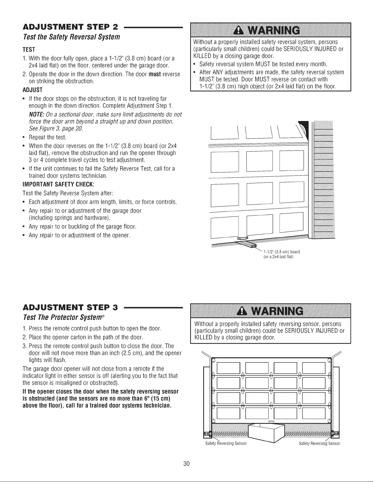
ADJUSTMENT STEP 2
Test the SafetyReversa/System
TEST
1. With the door fully open, place a 1-1/2" (3.8 cm) board (or a
2x4 laid flat) on the floor, centered under the garage door.
2. Operatethe door in the down direction. The door must reverse
on striking the obstruction.
ADJUST
* If the door stops on the obstruction, it is not traveling far
enough in the down direction. Complete Adjustment Step 1.
NOTE:On a sectional door, makesure limit adjustments do not
force the door arm beyond a straight up and down position.
SeeFigure 3, page20.
* Repeatthe test.
* When the door reverses on the 1-1/2" (3.8 cm) board (or 2x4
laid flat), removethe obstruction and run the opener through
3 or 4 complete travel cycles to test adjustment.
* If the unit continues to fail the Safety ReverseTest, call for a
trained door systems technician.
IMPORTANTSAFETYCHECK:
Test the Safety ReverseSystem after:
* Each adjustment of door arm length, limits, or force controls.
* Any repair to or adjustment of the garagedoor
(including springs and hardware).
* Any repair to or buckling of the garage floor.
* Any repair to or adjustment of the opener.
Without a properly installed safety reversalsystem, persons
(particularly small children) could be SERIOUSLYINJUREDor
KILLEDby a closing garagedoor.
* Safety reversalsystem MUST betested every month.
* After ANY adjustments are made,the safety reversal system
MUST be tested. Door MUST reverse on contact with
1-1/2" (3.8 cm) high object (or 2x4 laid flat) on the floor.
1
E ]
_" 1-1/2" (3.8 cm) board
(or a 2x4 laid flat)
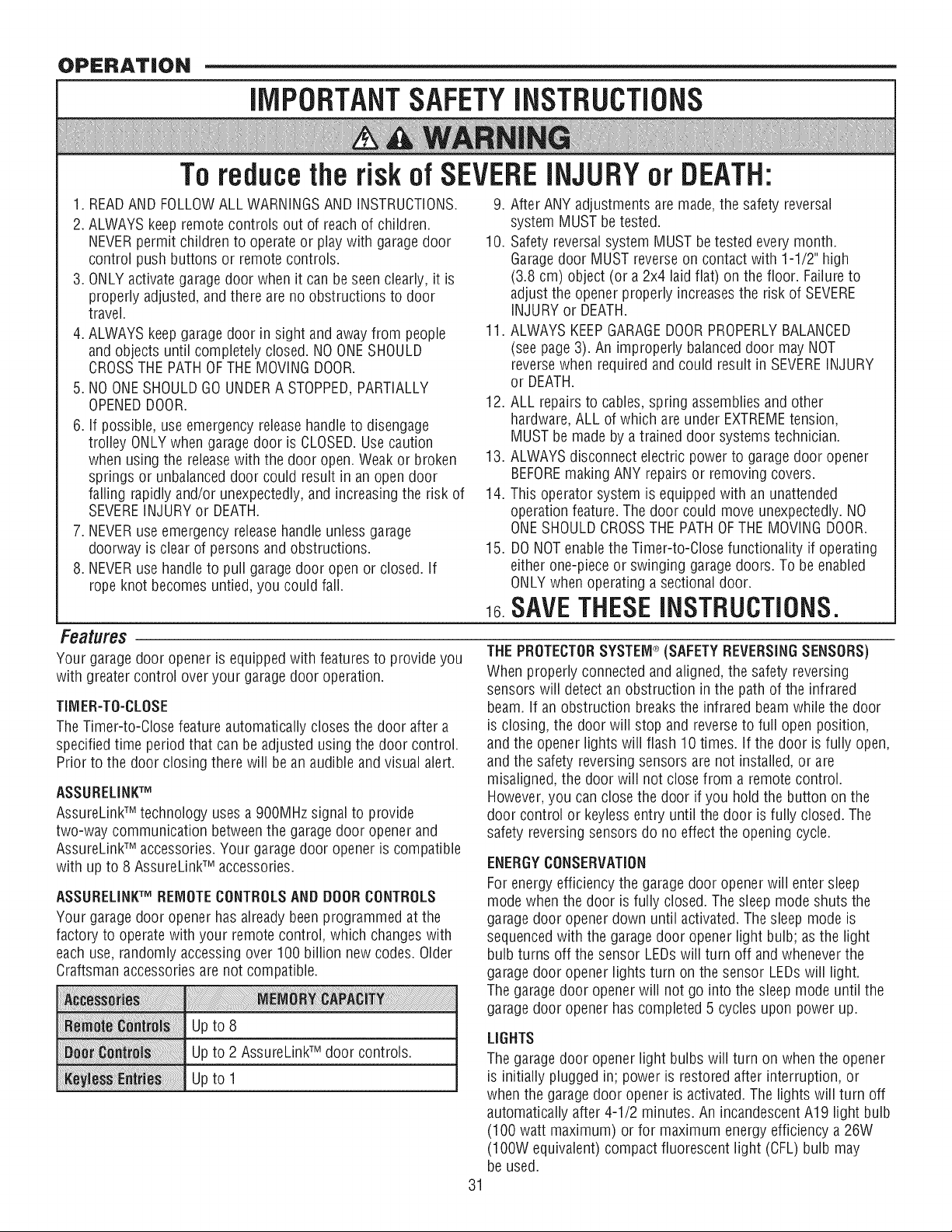
ADJUSTMENT STEP 3
Test The ProtectorSystem®
1. Pressthe remote control push button to open the door.
2. Placethe opener carton in the path of the door.
3. Pressthe remote control push button to close the door. The
door will not move more than an inch (2.5 cm), and the opener
lights will flash.
The garage door openerwiii not close from a remote if the
indicator light in either sensor is off (alerting you to the fact that
the sensor is misaligned or obstructed).
if the opener closesthe door when the safety reversingsensor
is obstructed (and the sensorsare nomore than 6" (15 cm)
above the floor), call for a trained door systems technician.
Without a properly installed safety reversing sensor, persons
(particularly small children) could be SERIOUSLYINJUREDor
KILLEDby a closing garagedoor.
Safety Reversing Sensor Safety Reversing Sensor
3O
OPERATION
llVlPORTANTSAFETYiNSTRUCTiONS
To reducethe risk of SEVEREiNJURYor DEATH:
1. READAND FOLLOWALL WARNINGSAND iNSTRUCTiONS.
2. ALWAYSkeep remote controls out of reach of children.
NEVERpermit children to operate or play with garage door
control push buttons or remote controls.
3. ONLYactivate garage door when it can be seen clearly, it is
properly adjusted, and there are no obstructions to door
travel.
4. ALWAYSkeep garage door in sight and away from people
and objects until completely closed. NOONESHOULD
CROSSTHE PATHOFTHE MOVINGDOOR.
5. NO ONESHOULDGO UNDERA STOPPED,PARTIALLY
OPENEDDOOR.
6. if possible, use emergency release handleto disengage
trolley ONLYwhen garage door is CLOSED.Use caution
when using the releasewith the door open. Weak or broken
springs or unbalanced door could result in an open door
failing rapidly and/or unexpectedly, and increasingthe risk of
SEVEREINJURY or DEATH.
7. NEVERuse emergency release handle unless garage
doorway is clear of persons and obstructions.
8. NEVERuse handle to pull garagedoor open or closed, if
rope knot becomes untied, you could fall.
9. After ANY adjustments are made, the safety reversal
system MUST be tested.
10. Safety reversalsystem MUST be tested every month.
Garagedoor MUST reverse on contact with 1-1/2" high
(3.8 cm) object (or a 2x4 laid flat) on the floor. Failureto
adjust the opener properly increases the risk of SEVERE
INJURYor DEATH.
11. ALWAYS KEEPGARAGEDOORPROPERLYBALANCED
(see page3). An improperly balanceddoor may NOT
reversewhen required and could result in SEVEREINJURY
or DEATH.
12. ALL repairs to cables, spring assembliesand other
hardware, ALL of which are under EXTREMEtension,
MUST be made by a trained door systems technician.
13. ALWAYSdisconnect electric power to garage door opener
BEFOREmaking ANY repairs or removing covers.
14. This operator system is equipped with an unattended
operation feature. The door could move unexpectedly. NO
ONESHOULDCROSSTHE PATHOFTHE MOVINGDOOR.
15. DONOTenablethe Timer-to-Close functionality if operating
either one-piece or swinging garage doors. To be enabled
ONLYwhen operating a sectional door.
16SAVETHESEINSTRUCTIONS.
Features
Your garage door opener is equipped with features to provide you
with greater control over your garagedoor operation.
TIMER-TO-CLOSE
The Timer-to-Close feature automatically closes the door after a
specified time period that can be adjusted using the door control.
Prior to the door closing there will be an audible and visual alert.
ASSURELINKTM
AssureLinkTM technology uses a 900MHz signal to provide
two-way communication between the garage door opener and
AssureLinkTM accessories. Your garagedoor opener is compatible
with up to 8 AssureLinkTM accessories.
ASSURELINKTM REMOTECONTROLSAND DOORCONTROLS
Your garage door opener has already been programmed at the
factory to operatewith your remote control, which changes with
each use, randomly accessing over 100 billion new codes. Older
Craftsman accessories are not compatible.
Up to 8
Up to 2 AssureLinkTM door controls.
Upto 1
31
THEPROTECTORSYSTEM®(SAFETY REVERSINGSENSORS)
When properly connected and aligned, the safety reversing
sensors will detect an obstruction in the path of the infrared
beam. if an obstruction breaks the infraredbeam while the door
is closing, the door will stop and reverse to full open position,
and the opener lightswill flash 10 times, if the door isfully open,
and the safety reversing sensors are not installed,or are
misaligned, the door will not close from a remote control.
However,you can close the door if you hold the button on the
door control or keyless entry until the door is fully closed. The
safety reversing sensors do no effect the opening cycle.
ENERGYCONSERVATION
For energy efficiency the garage door opener will enter sleep
mode when the door is fully closed. The sleep mode shuts the
garagedoor opener down until activated. The sleep mode is
sequencedwith the garage door opener lightbulb; as the light
bulb turns off the sensor LEDs will turn off and whenever the
garagedoor opener lightsturn on the sensor LEDswill light.
The garage door openerwill not go into the sleep mode until the
garagedoor opener has completed 5 cycles upon power up.
LIGHTS
The garage door opener light bulbs will turn on when the opener
is initiallyplugged in; power is restored after interruption, or
when the garagedoor opener is activated. The lights wiii turn off
automatically after 4-1/2 minutes. An incandescentA19 light bulb
(100 watt maximum) or for maximum energy efficiency a 26W
(100W equivalent) compact fluorescent light(CFL) bulb may
be used.
USINGYOUR GARAGEDOOROPENER
The garage door opener can be activated through a wall-mounted
door control, remote control, wireless keyless entry or
AssureLinkTM accessory.
When the door is closed and the garage door opener is activated
the door will open. If the door senses an obstruction or is
interrupted while opening the door will stop. When the door is in
any position other than closed and the garage door opener is
activated the door will close. If the garage door opener senses an
obstruction while closing, the door will reverse. If the obstruction
interrupts the sensor beam the garagedoor opener lightswill
blink 10 times. However, you can close the door if you hold the
button on the door control or keyiess entry until the door is fully
closed. The safety reversing sensors do no effect the opening
cycle. The safety reversing sensor must be connected and aligned
correctly before the garage door opener will move in the down
direction.
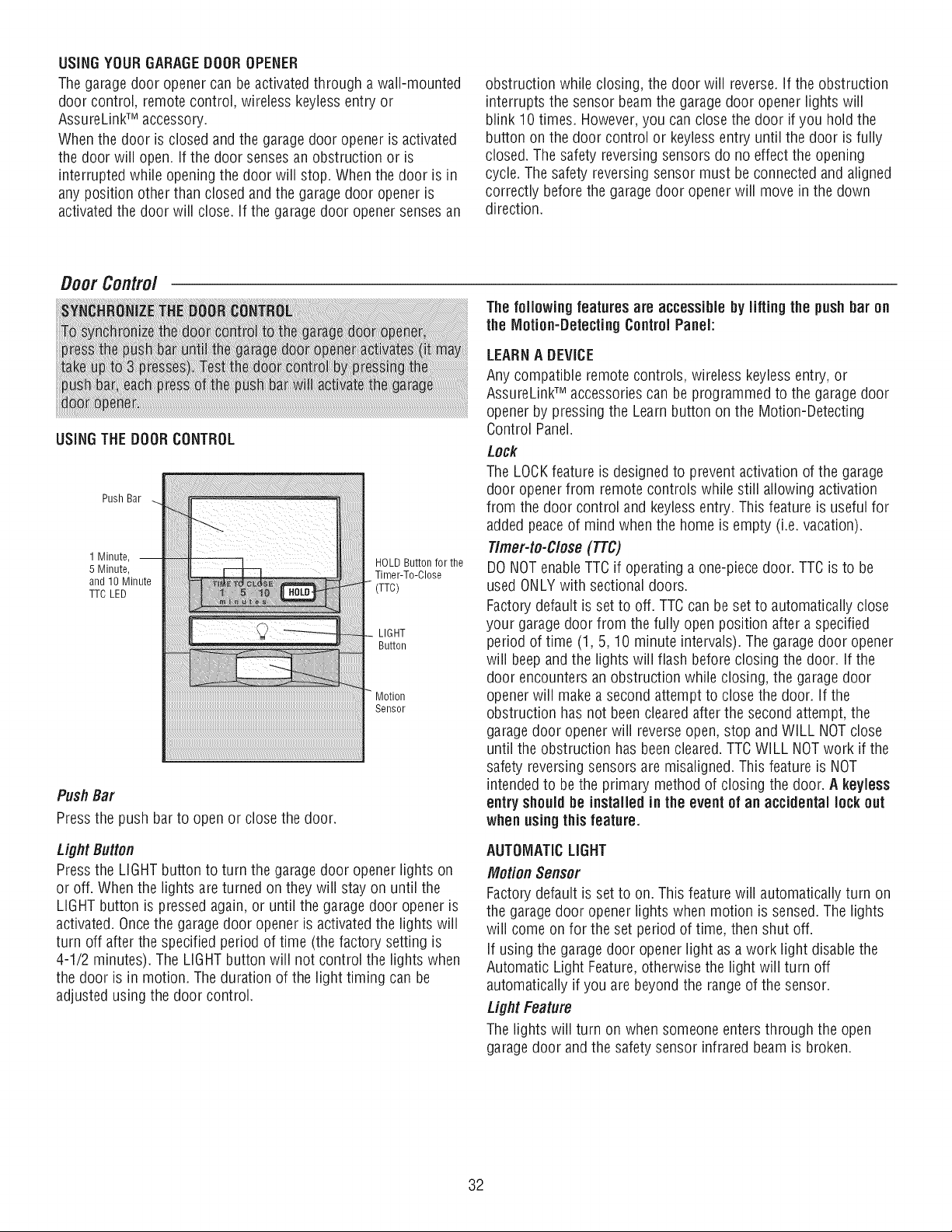
Door Control
USINGTHE DOORCONTROL
Push Bar
1 Minute, --
5 Minute,
and 10 Minute
TTC LED
HOLDButtonfor the
Timer-To-Close
LIGHT
Button
Sensor
PushBar
Press the push barto open orclosethe door.
Light Button
Press the LIGHT button to turn the garage door opener lights on
or off. When the lights are turned on they will stay on until the
LIGHT button is pressed again, or until the garagedoor opener is
activated. Oncethe garagedoor opener is activatedthe lights will
turn off after the specified period of time (the factory setting is
4-1/2 minutes). The LIGHTbutton will not control the lights when
the door is in motion. The duration of the light timing can be
adjusted using the door control.
The following features are accessible by lifting the push bar on
the Motion-Detecting Control Paneh
LEARNA DEVICE
Any compatible remote controls, wireless keyiessentry, or
AssureLinkTM accessoriescan be programmed to the garage door
opener by pressing the Learn button on the Motion-Detecting
Control Panel.
Lock
The LOCKfeature is designed to prevent activation of the garage
door opener from remote controls while still allowing activation
from the door control and keyiess entry. This feature is useful for
added peaceof mind when the home is empty (i.e. vacation).
Timer-to-Close (TTC)
DO NOTenable TTCif operating a one-piece door. TTC is to be
used ONLYwith sectional doors.
Factorydefault is set to off. TTCcan be set to automatically close
your garage door from the fully open position after a specified
period of time (1, 5, 10 minute intervals). The garage door opener
will beep and the lights will flash before closing the door. If the
door encounters an obstruction while closing, the garagedoor
openerwill make a second attempt to close the door. If the
obstruction has not been cleared after the second attempt, the
garagedoor opener will reverseopen, stop and WILL NOTclose
until the obstruction has been cleared. TTCWiLL NOTwork if the
safety reversing sensors are misaligned. This feature is NOT
intended to be the primary method of closing the door. A keyless
entry should be installed in the event of an accidental lock out
when usingthis feature.
AUTOMATICLIGHT
Motion Sensor
Factorydefault is set to on. This feature will automatically turn on
the garagedoor opener lights when motion is sensed. The lights
will come on for the set period of time, then shut off.
If using the garage door opener light as a work light disable the
Automatic Light Feature,otherwise the light will turn off
automatically if you are beyond the rangeof the sensor.
Light Feature
The lights will turn on when someone enters through the open
garagedoor and the safety sensor infrared beam is broken.
32
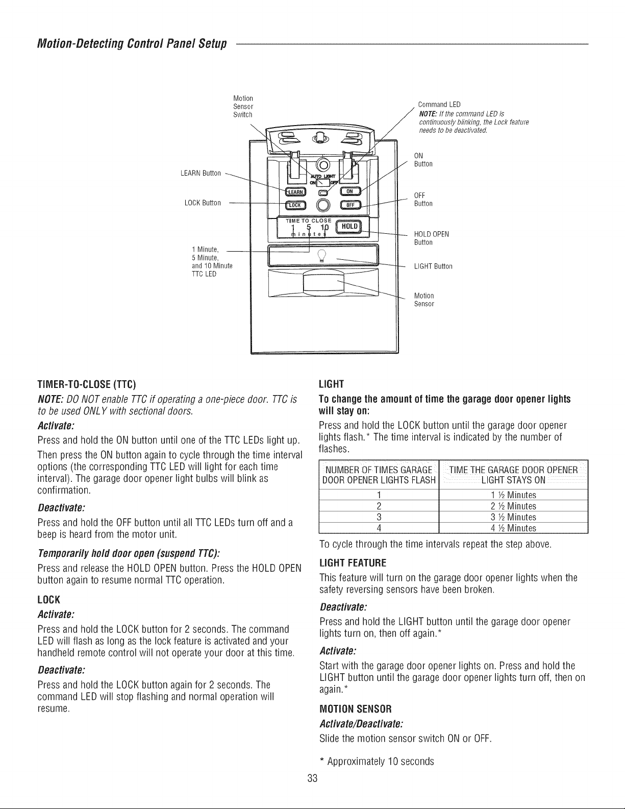
Motion-DetectingControl Panel Setup
Motion
Sensor .. Command LED
Switch J NOTE: If the command LED is
. _ continuously bfinking, the Lock feature
_ needs to be deactivated.
J Button
LEARNButton
II I_ _ _IlU _ OFF
I L= _'"_ ___ _ HOLD OPEN
I --_' Button
1Minute, L I __
5 Minute,
and 10 Minute - LIGHT Button
TTC LED I__
Motion
Sensor
TIMER-TO-CLOSE(TTC)
NOTE:DO NOTenable TTCif operating a one-piece door. TTCis
to be used ONLYwith sectional doors.
Activate:
Pressand hold the ON button until one of the TTC LEDs light up.
Then press the ON button again to cycle through the time interval
options (the corresponding TTC LEDwill light for each time
interval). The garage door opener light bulbs will blink as
confirmation.
Deactivate:
Pressand hold the OFFbutton until all TTC LEDsturn off and a
beepis heardfrom the motor unit.
Temporarily hold door open (suspendTTC):
Pressand releasethe HOLDOPENbutton. Pressthe HOLDOPEN
button again to resume normal TTCoperation.
LOCK
Activate:
Pressand hold the LOCKbutton for 2 seconds. The command
LEDwill flash as long as the lock feature is activatedand your
handheld remote control will not operate your door at this time.
Deactivate:
Pressand hold the LOCKbutton again for 2 seconds. The
command LEDwill stop flashing and normal operation will
resume.
LIGHT
To changethe amount of time the garage door opener lights
will stay on:
Press and hold the LOCKbutton until the garage door opener
lights flash.* The time interval is indicated by the number of
flashes.
NUMBEROFTIMESGARAGE
DOOROPENERLIGHTSFLASH
1
2
3
4
TIME THEGARAGEDOOROPENER
LIGHTSTAYSON
1½ Minutes
2 ½ Minutes
3 ½ Minutes
4 ½ Minutes
To cycle through the time intervals repeat the step above.
LIGHTFEATURE
This feature wiii turn on the garagedoor opener lights when the
safety reversing sensors have been broken.
Deactivate:
Press and hold the LIGHT button until the garage door opener
lights turn on, then off again.*
Activate:
Start with the garage door opener lights on. Press and hold the
LIGHT button until the garagedoor opener lights turn off, then on
again.*
MOTIONSENSOR
Activate/Deactivate:
Slide the motion sensor switch ON or OFF.
* Approximately 10 seconds
33
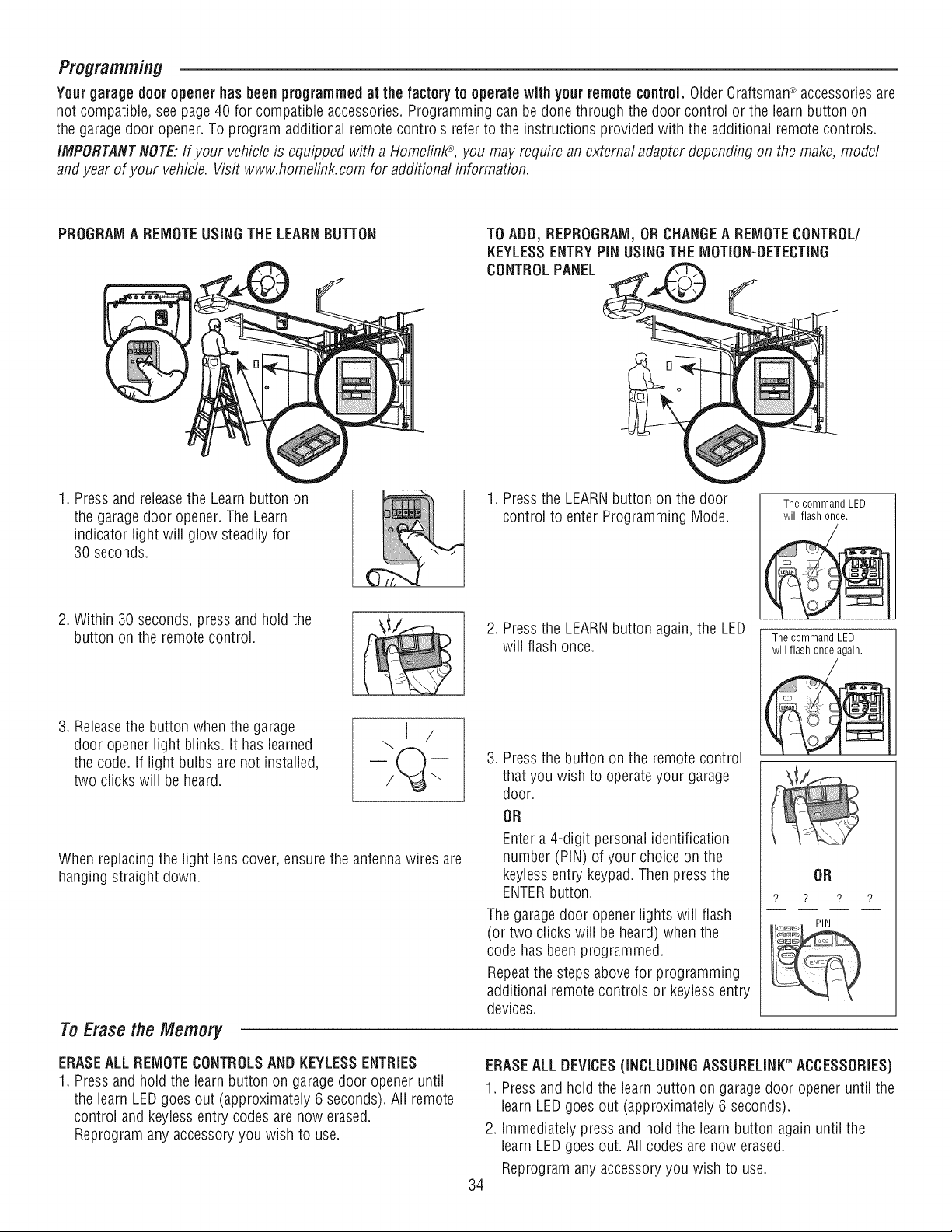
Programming
Your garage door opener has been programmed at the factory to operate with your remotecontrol. Older Craftsman_ accessoriesare
not compatible, see page 40 for compatible accessories. Programming can be done through the door control or the learn button on
the garagedoor opener. To program additional remote controls refer to the instructionsprovided with the additional remote controls.
IMPORTANTNOTE:If your vehicle is equipped with a Homefinl_, you may require an external adapter depending on the make, model
and year of your vehicle. Vis# www.homefink.com for additional information.
PROGRAMA REMOTEUSINGTHE LEARNBUTTON
TO ADD, REPROGRAIVI,ORCHANGEA REMOTECONTROL/
KEYLESSENTRYPiN USINGTHEMOTION-DETECTING
CONTROLPANEL
(
1. Pressand releasethe Learnbutton on
the garage door opener. The Learn
indicator light will glow steadily for
30 seconds.
2. Within 30 seconds, press and hold the
button on the remote control.
3. Releasethe button when the garage
door opener light blinks. It has learned
the code. if light bulbs are not installed,
two clicks will be heard.
When replacing the light lens cover, ensure the antennawires are
hanging straight down.
ToErasethe Memory
1. Pressthe LEARN button on the door [ ThecommandLED ]
control to enter Programming Mode. / will flashonce. /
2. Pressthe LEARN button again, the LED
will flash once.
3. Pressthe button on the remote control
that you wish to operateyour garage
door.
OR
Enter a 4-digit personal identification
number (PIN) of your choice on the
keyless entry keypad.Then press the
ENTERbutton.
The garage door opener lights will flash
(or two clicks will be heard) when the
code has beenprogrammed.
Repeatthe steps above for programming
additional remote controls or keyless entry
devices.
The command LED
will flash once again.
OR
? ? ? ?
ERASEALL REMOTECONTROLSANDI{EYLESSENTRIES
1. Pressand hold the learn button on garage door opener until
the learn LEDgoes out (approximately 6 seconds). All remote
control and keyiess entry codes are now erased.
Reprogram any accessory you wish to use.
ERASEALL DEVICES(INCLUDINGASSURELINKTM ACCESSORIES)
1. Pressand hold the learn button on garage door opener until the
learn LEDgoes out (approximately 6 seconds).
2. Immediately press and hold the learn button again until the
learn LEDgoes out. All codes are now erased.
Reprogramany accessoryyou wish to use.
34
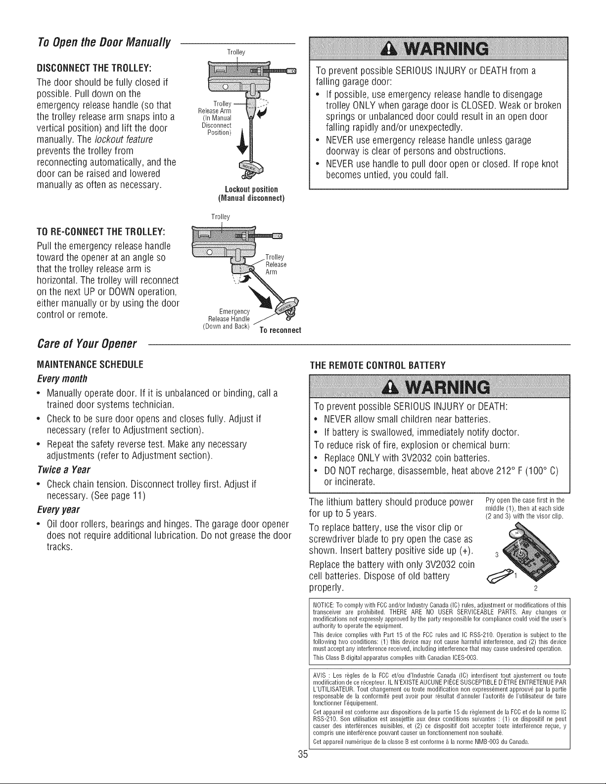
To Openthe Door Manually
DISCONNECTTHE TROLLEY:
The door should be fully closed if
possible. Pull down on the
emergency releasehandle (so that
the trolley releasearm snaps into a
vertical position) and lift the door
manually. The lockout feature
prevents the trolley from
reconnecting automatically, and the
door can be raised and lowered
manually as often as necessary.
Trolley
Trolle
ReleaseArm
(In Manual
Disconnect
Position)
Lockoutposition
(Manualdisconnect)
To prevent possible SERIOUSINJURYor DEATHfrom a
falling garagedoor:
. if possible, use emergency release handleto disengage
trolley ONLY when garage door is CLOSED.Weak or broken
springs or unbalanced door could result in an open door
falling rapidly and/or unexpectedly.
. NEVERuse emergency releasehandle unless garage
doorway is clear of persons and obstructions.
. NEVERuse handle to pull door open or closed. If rope knot
becomes untied, you could fall.
TO RE-CONNECTTHETROLLEY:
Pull the emergency releasehandle
toward the opener at an angle so
that the trolley releasearm is
horizontal. The trolley will reconnect
on the next UP or DOWNoperation,
either manually or by using the door
control or remote.
Careof YourOpener
Trolley
Release
Arm
ReieEa_e I_gaennd%Y__
J
(Down and Back) To reconnect
MAINTENANCESCHEDULE
Everymonth
* Manually operate door. If it is unbalancedor binding, call a
trained door systems technician.
. Checkto be sure door opens and closes fully. Adjust if
necessary(refer to Adjustment section).
. Repeatthe safety reversetest. Make any necessary
adjustments (refer to Adjustment section).
Twice a Year
_ Check chain tension. Disconnect trolley first. Adjust if
necessary. (See page 11)
Everyyear
, Oil door rollers, bearings and hinges. The garagedoor opener
does not require additional lubrication. Do not grease the door
tracks.
THEREMOTECONTROLBATTERY
To prevent possible SERIOUSINJURYor DEATH:
. NEVERallow small children near batteries.
. If battery is swallowed, immediately notify doctor.
To reduce risk of fire, explosion or chemical burn:
. ReplaceONLYwith 3V2032 coin batteries.
. DONOT recharge, disassemble, heat above 212° F (100° C)
or incinerate.
The lithium battery should produce power
for up to 5 years.
To replace battery, use the visor clip or
screwdriver blade to pry open the caseas
shown, insert battery positive side up (+).
Replacethe battery with only 3V2032 coin
cell batteries. Dispose of old battery
properly.
Pry open the case first in the
middle (1), then at each side
(2 and 3) with the visor clip.
3
2
NOTICE:To comply with FCCand/or Industry Canada(IC) rules, adjustment or modifications of this
transceiver are prohibited. THERE ARE NO USER SERVICEABLEPARTS. Airy changes or
modifications not expressly approved by the party responsiblefor compliance could void the user's
authority to operate the equipment.
This device complies with Part 15 of the FCCrules and IC RSS-210. Operation is subject to the
following two conditions: (1) this device may not cause harmful interference,and (2) this device
must accept any interferencereceived, including interferencethat may cause undesired operation.
This ClassB digital apparatuscomplies with CanadianICES-003.
35
AVIS : Les r_gles de la FCC et/ou d'lndustrie Canada (IC) interdisent tout ajustement ou toute
modification de ce r@epteur. IL N'EXISTE AUCUNE PIECE SUSCEPTIBLE D'ETRE ENTRETENUE PAR
L'UTILISATEUR, Tout changement ou toute modification non express6ment approuv6 par la partie
responsable de la conformit6 peut avoir pour r6sultat d'annuler I'autorit6 de rutilisateur de faire
fonctionner 1'6quipement,
Cet appareil est conforme aux dispositions de la partie 15 du r6glement de la FCC et de la norme IC
RSS-210. Son utilisation est assujettie aux deux conditions suivantes : (1) ce dispositif ne peut
causer des interf6rences nuisibles, et (2) ce dispositif dolt accepter toute interf6rence reque, y
compris une interf6rence pouvant causer un fonctionnement non souhait&
Cet appareil num6rique de la classe Best conforme 5 la norme NMB-003 du Canada.
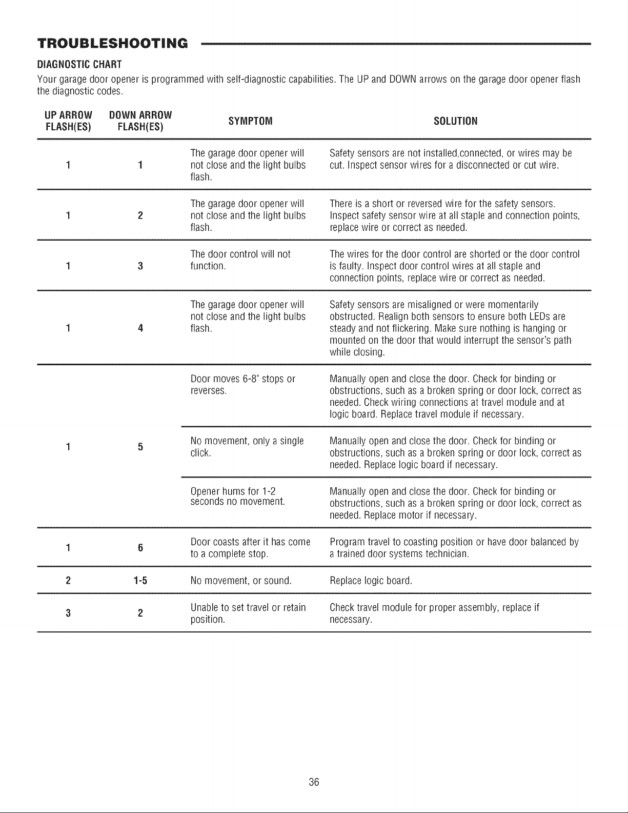
TROUBLESHOOTING
DIAGNOSTICCHART
Your garage door opener is programmed with self-diagnostic capabilities. The UP and DOWNarrows on the garage door opener flash
the diagnostic codes.
UP ARROW DOWNARROW
SYMPTOM SOLUTION
FLASH(ES) FLASH(ES)
The garagedoor opener will
not close and the light bulbs
flash.
Safety sensors are not installed,connected, or wires may be
cut. Inspect sensor wires for a disconnected or cut wire.
The garagedoor opener will
not close and the light bulbs
flash.
There is a short or reversed wire for the safety sensors.
Inspect safety sensor wire at all staple and connection points,
replacewire or correct as needed.
The door control will not
function.
The wires for the door control areshorted or the door control
is faulty. Inspect door control wires at all staple and
connection points, replace wire or correct as needed.
The garagedoor opener will
not close and the light bulbs
flash.
Safety sensors are misaligned or were momentarily
obstructed. Realign both sensors to ensure both LEDsare
steady and not flickering. Make sure nothing is hanging or
mounted on the door that would interrupt the sensor's path
while closing.
Door moves 6-8" stops or
reverses.
Manually open and close the door. Checkfor binding or
obstructions, such as a broken spring or door lock, correct as
needed. Checkwiring connections at travel module and at
logic board. Replacetravel module if necessary.
No movement, only a single
click.
Manually open and close the door. Checkfor binding or
obstructions, such as a broken spring or door lock, correct as
needed. Replace logic board if necessary.
Openerhums for 1-2
seconds no movement.
Manually open and close the door. Checkfor binding or
obstructions, such as a broken spring or door lock, correct as
needed. Replace motor if necessary.
Door coasts after it has come Program travel to coasting position or have door balanced by
1 6
to a complete stop. a trained door systems technician.
2 1-5 No movement, or sound. Replacelogic board.
Unableto set travel or retain Check travel module for proper assembly, replace if
3 2
position, necessary.
36
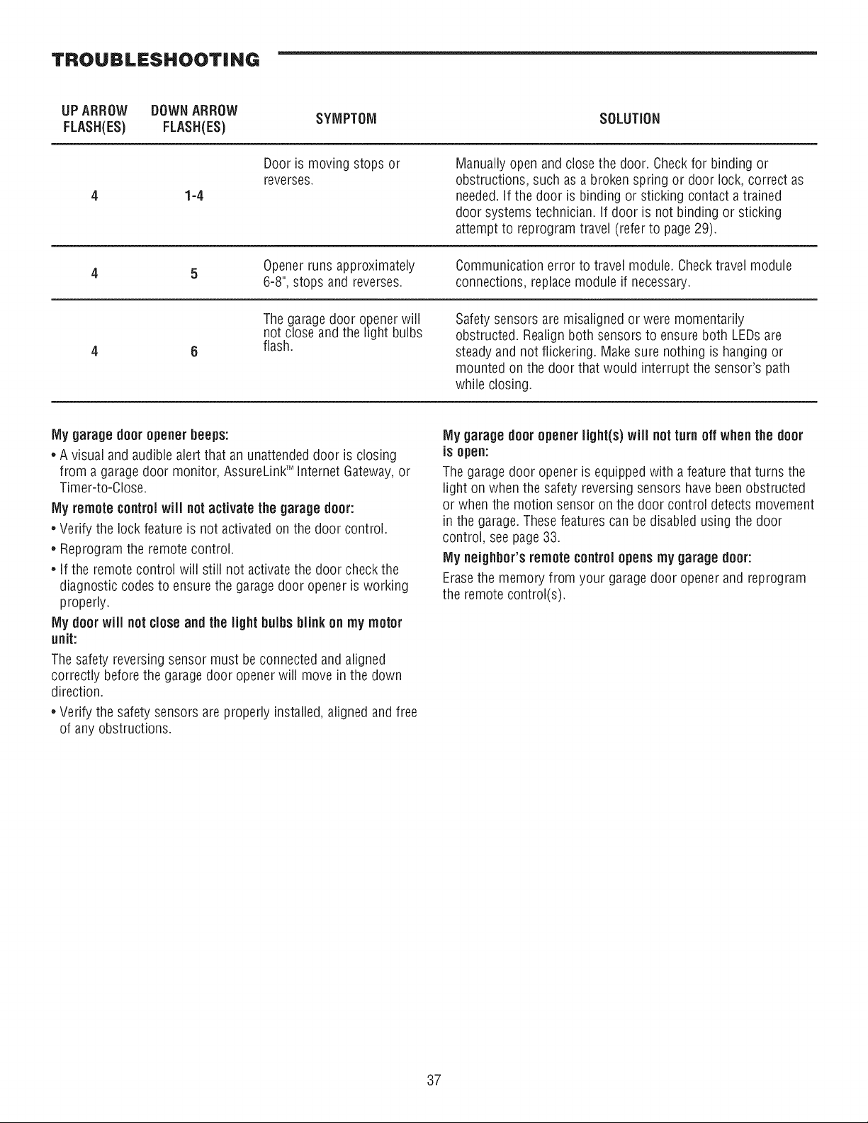
TROUBLESHOOTING
UP ARROW DOWNARROW
SYMPTOM SOLUTION
FLASH(ES) FLASH(ES)
1-4
Door is moving stops or
reverses.
Manually open and close the door. Checkfor binding or
obstructions, such as a broken spring or door lock, correct as
needed, if the door is binding or sticking contact a trained
door systems technician. If door is not binding or sticking
attempt to reprogram travel (refer to page 29).
Openerruns approximately
6-8", stops and reverses.
Communication error to travel module. Checktravel module
connections, replace module if necessary.
The garagedoor opener will
not close and the light bulbs
flash.
Safety sensors are misaligned or were momentarily
obstructed. Realign both sensors to ensure both LEDsare
steady and not flickering. Make sure nothing is hanging or
mounted on the door that would interrupt the sensor's path
while closing.
My garage door opener beeps:
• A visual and audible alert that an unattended door is closing
from a garage door monitor, AssureLinkTMInternet Gateway,or
Timer-to-Close.
My remote controlwill not activate the garage door:
• Verify the lock feature is not activated on the door control.
• Reprogram the remote control.
• If the remote control wiii still not activatethe door check the
diagnostic codes to ensure the garage door opener is working
properly.
My door will notclose and the light bulbs blink on rnymotor
unit:
The safety reversing sensor must be connected and aligned
correctly before the garage door opener will move in the down
direction.
• Verify the safety sensors are properly installed, aligned and free
of any obstructions.
My garage door opener light(s) will notturn off whenthe door
is open:
The garage door opener is equipped with a feature that turns the
light on when the safety reversing sensors have been obstructed
or when the motion sensor on the door control detects movement
in the garage. These features can be disabled using the door
control, see page 33.
IVlyneighbor'sremote controlopens rny garage door:
Erasethe memory from your garage door opener and reprogram
the remote control(s).
37
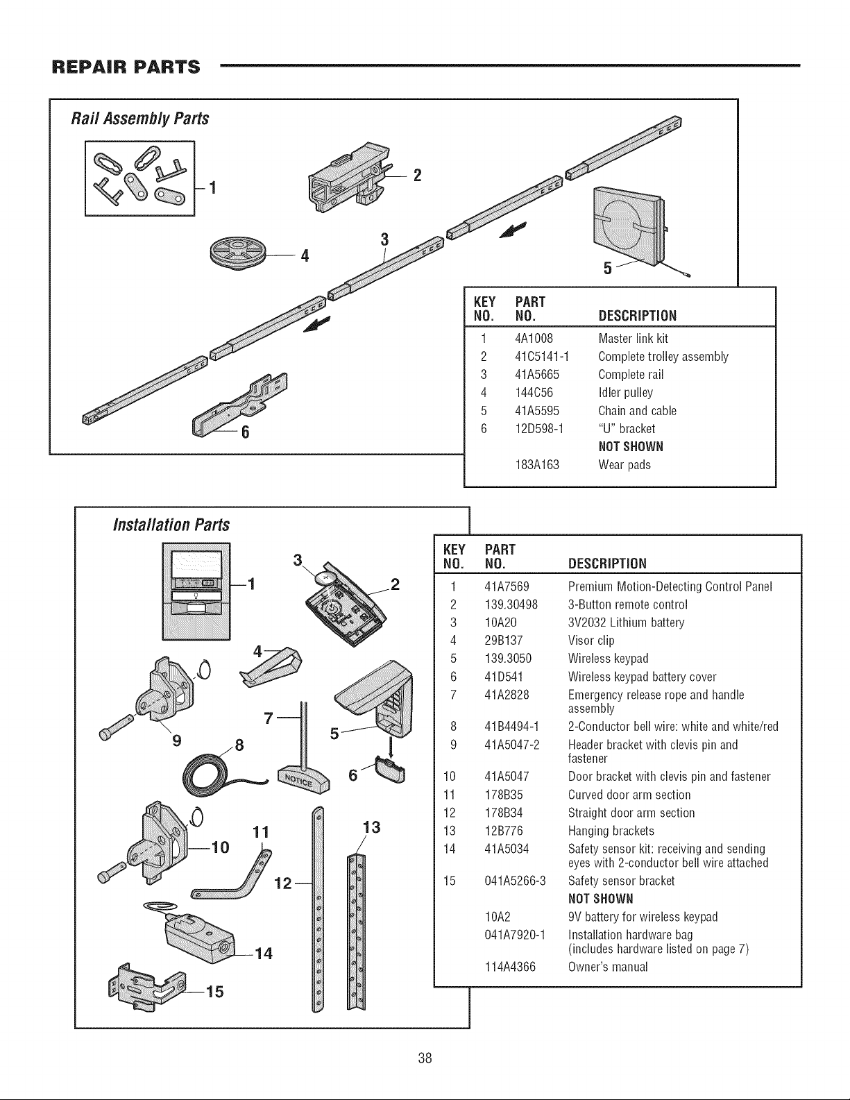
REPAIR PARTS
Raft Assemb/yParts
4
5
6
144C56
41A5595
12D598-1
183A163
Idler pulley
Chain and cable
"U" bracket
NOT SHOWN
Wear pads
/nsta//ationParts
14
3\
13
_]
KEY
NO.
1
2
3
4
5
6
7
8
9
10
11
12
13
14
15
PART
NO.
41A7569
139.30498
10A20
29B137
139.3050
41D541
41A2828
41B4494-1
41A5047-2
41A5047
178B35
178B34
12B776
41A5034
041A5266-3
10A2
041A7920-1
114A4366
DESCRIPTION
Premium Motion-Detecting Control Panel
3-Button remote control
3V2032 Lithium battery
Visor clip
Wireless keypad
Wireless keypad battery cover
Emergency release rope and handle
assembly
2-Conductor bell wire: white and white/red
Header bracket with clevis pin and
fastener
Door bracket with clevis pin and fastener
Curved door arm section
Straight door arm section
Hanging brackets
Safety sensor kit: receiving and sending
eyes with 2-conductor bell wire attached
Safety sensor bracket
NOT SHOWN
9V battery for wireless keypad
Installation hardware bag
(includes hardware listed on page 7)
Owner's manual
38
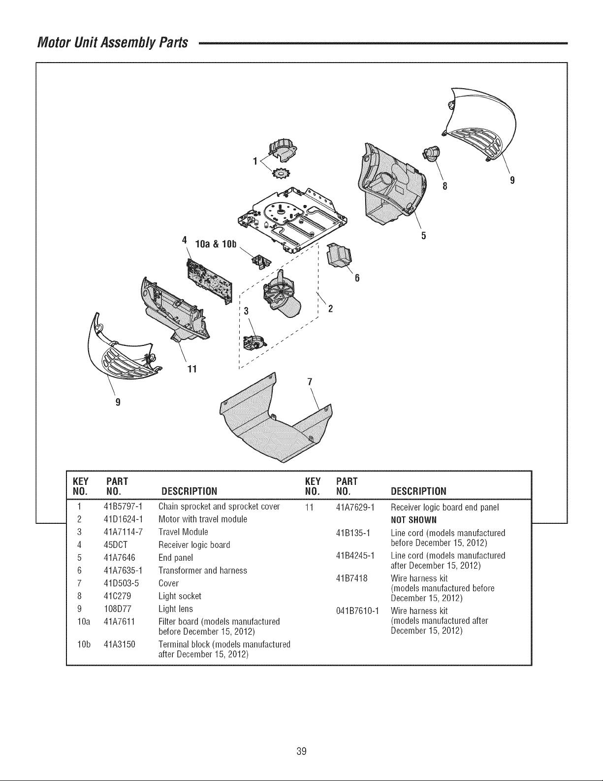
Motor Unit Assemb/yParts
KEY PART
NO, NO,
1 41B5797-1
2 41D1624-1
3 41A7114-7
4 45DCT
5 41A7646
6 41A7635-1
7 41D503-5
8 41C279
9 108D77
10a 41A7611
10b 41A3150
11
7
KEY PART
DESCRIPTION NO. NO. DESCRIPTION
Chain sprocket and sprocket cover 11 41A7629-1
Motor with travel module
Travel Module 41B135-1
Receiver logic board
End panel 41B4245-1
Transformer and harness
Cover 41B7418
Light socket
Light lens 041B7610-1
Filter board (models manufactured
before December 15, 2012)
Terminal block (models manufactured
after December 15, 2012)
Receiver logic board end panel
NOTSHOWN
Line cord (models manufactured
before December 15, 2012)
Line cord (models manufactured
after December 15, 2012)
Wire harness kit
(models manufactured before
December 15, 2012)
Wire harness kit
(models manufactured after
December 15, 2012)
39
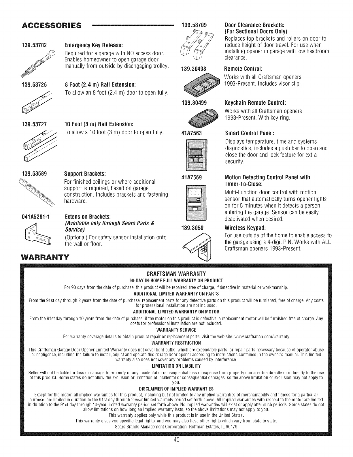
ACCESSORIES
139.53702
139.53726
139.53727
Emergency Key Release:
Required for a garagewith NO accessdoor.
Enableshomeowner to open garagedoor
manually from outside by disengaging trolley.
8 Foot (2.4 m) Rail Extension:
To allow an 8 foot (2.4 m) door to open fully.
18 Foot (3 m) Rail Extension:
To allow a 10 foot (3 m) door to open fully.
139.53709
139.30498
139.30499
41A7563
Door Clearance Brackets:
(For Sectional Doors0nly)
Replacestop brackets and rollers on door to
reduce height of door travel. For use when
installing opener in garagewith low headroom
clearance.
Remote Controh
Works with aii Craftsman openers
1993-Present. includes visor clip.
Keychain Remote Controh
Works with all Craftsman openers
1993-Present. With key ring.
Smart Control Paneh
Displaystemperature, time and systems
diagnostics, includes a push bar to open and
close the door and lock featurefor extra
security.
139.53589
Support Brackets:
For finished ceilings or where additional
support is required, based on garage
construction, includes brackets and fastening
hardware.
041A5281-1 ExtensionBrackets:
(Avai/afl/e on/y through Seam Parts &
Service)
(Optional) For safety sensor installation onto
the wall or floor.
WARRANTY
41A7569
139.3050
Motion Detecting Control Panel with
Timer-To-Close:
Multi-Function door control with motion
sensor that automatically turns opener lights
on for 5 minutes when it detects a person
entering the garage. Sensor can be easily
deactivatedwhen desired.
Wireless Keypad:
For use outside of the home to enableaccessto
the garageusing a 4-digit PiN. Works with ALL
Craftsmanopeners 1993-Present.
CRAFTSMANWARRANTY
90-BAYIN-HOMEFULLWARRANTYONPRODUCT
For 90 days from the date of purchase, this product will be repaired, free of charge, if defective in material or workmanship.
ADDiTiONAL LiMiTED WARRANTY ON PARTS
From the 91st day through 2 years from the date of purchase, replacement parts for any defective parts on this product will be furnished, free of charge. Any costs
for professional installation are not included.
ADDITIONAL LiMiTED WARRANTY ONMOTOR
From the 91st day through 10 years from the date of purchase, if the motor on this product is defective, a replacement motor will be furnished free of charge. Any
costs for professional installation are not included.
WARRANTYSERVICE
For warranty coverage details to obtain product repair or replacement parts, visit the web site: www.craftsman.com/warranty
WARRANTY RESTRiCTiON
This Craftsman Garage Door Opener Limited Warranty does not cover light bulbs, which are expendable parts, or repair parts necessary because of operator abuse
or negligence, including the failure to install, adjust and operate this garage door opener according to instructions contained in the owner's manual, This limited
warranty also does not cover any problems caused by interference,
LIMITATION ON LIABILITY
Seller will not be liable for loss or damage to property or any incidental or consequential loss or expensefrom property damage due directly or indirectly to the use
of this product, Some states do not allow the exclusion or limitation of incidental or consequential damages, so the above limitation or exclusion may not apply to
you.
DISCLAIMEROF IMPLIED WARRANTIES
Exceptfor the motor, all implied warranties for this product, including but not limited to any implied warranties of merchantability and fitness for a particular
purpose, are limited in duration to the 91st day through 2-year limited warranty period set forth above. All implied warranties with respect to the motor are limited
in duration to the 91st day through 10-year limited warranty period set forth above. No implied warranties will exist or apply after such periods. Some states do not
allow limitations on how long an implied warranty lasts, so the above limitations may not apply to you.
This warranty applies only while this product is in use in the United States.
This warranty gives you specific legal rights, and you may also have other rights which vary from state to state.
Sears Brands Management Corporation, Hoffman Estates, IL 60179
4O

NOTES
41
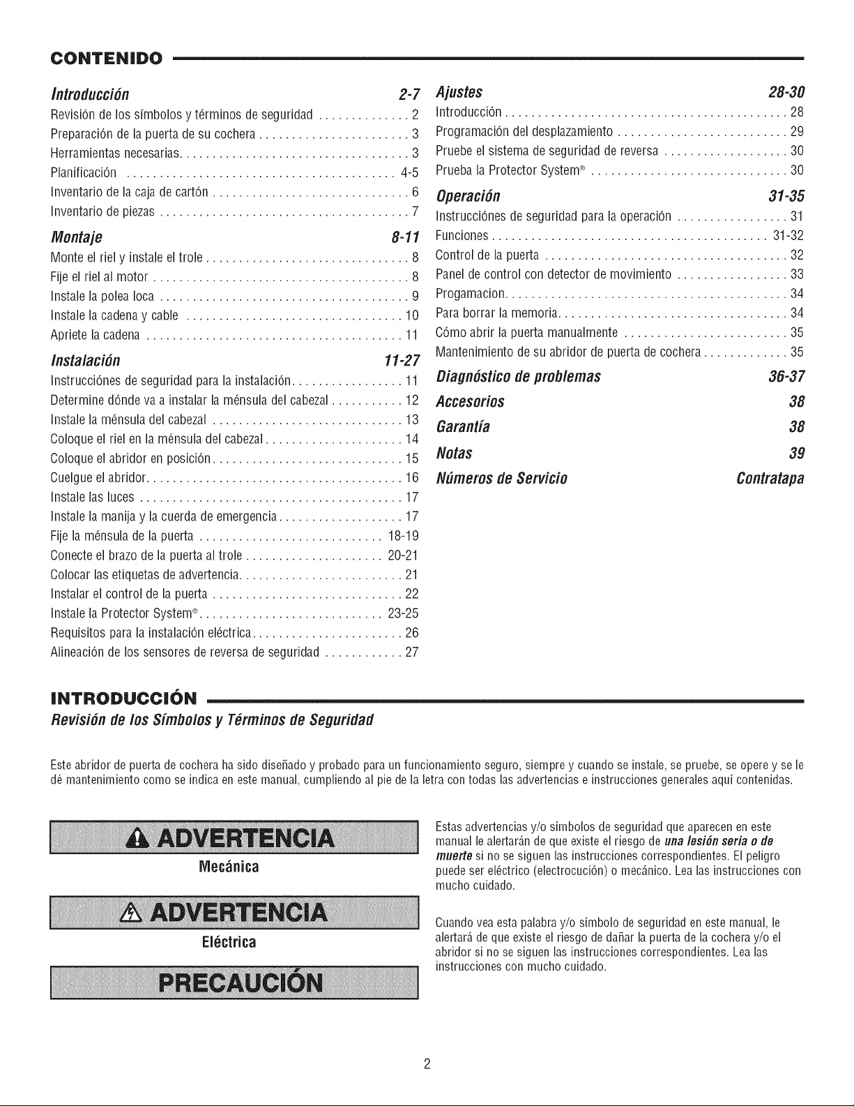
CONTENIDO
/ntroducci#n 2-7
RevisiOnde lossimbolos y t_rminos de seguridad .............. 2
PreparaciOndela puertade su cochera....................... 3
Herramientasnecesarias................................... 3
PlanificaciOn ......................................... 4-5
Inventariode la caja de carton .............................. 6
Inventariode piezas ...................................... 7
/Vlontaje 8-11
Monteel riel y instaleel trole ............................... 8
Fijeel riel al motor ....................................... 8
Instale la poleaIoca ...................................... 9
Instale la cadenay cable ................................. 10
Aprietela cadena ....................................... 11
Instalaci#n 11-27
InstrucciOnesde seguridadpara la instalaciOn................. 11
DeterminedOndeva a instalar la mensuladel cabezal........... 12
Instale la m_nsuladelcabezal ............................. 13
Coloqueel riel en la m_nsuladel cabezal..................... 14
Coloqueel abridor en posiciOn............................. 15
Cuelgueel abridor....................................... 16
Instale las luces ........................................ 17
Instale la manija y lacuerda de emergencia................... 17
Fije lamensula de la puerta ............................ 18-19
Conecteel brazode la puertaal trole ..................... 20-21
Colocarlas etiquetasdeadvertencia......................... 21
Instalarel controlde la puerta ............................. 22
Instale la ProtectorSystem®............................ 23-25
Requisitosparala instalaciOnel_ctrica....................... 26
AlineaciOnde los sensoresdereversade seguridad ............ 27
Ajustes 28-30
IntroducciOn........................................... 28
ProgramaciOndel desplazamiento.......................... 29
Pruebeel sistema de seguridadde reversa ................... 30
Pruebala ProtectorSystem® .............................. 30
Operaci#n 31-35
InstrucciOnesde seguridadpara la operaciOn................. 31
Funciones.......................................... 31-32
Controlde la puerta ..................................... 32
Panelde control con detectorde movimiento ................. 33
Progamacion........................................... 34
Paraborrar la memoria................................... 34
COmoabrir la puertamanualmente ......................... 35
Mantenimientodesu abridorde puertade cochera............. 35
Oiagn#stico de problemas 36-37
Accesorios 38
Garantia 38
Notas 39
N#meros de Servicio Contratapa
INTRODUCCI()N
Revisi#n de los Simbolos y Tbrminos de Seguridad
Este abridor de puerta de cochera ha sido dise_ado y probado para un funcionamiento seguro, siempre y cuando se instale, se pruebe, se opere y se le
d(_mantenimiento como se indica en este manual, cumpliendo al pie de la letra con todas las advertencias e instrucciones generales aqui contenidas.
Mec_nica
EI6ctrica
Estas advertencias y/o simbolos de seguridad que aparecen en este
manual le alertar_,nde que existe el riesgo de una lesidn seria o de
muerte si no se siguen las instruccionescorrespondientes. El peligro
puede ser el(_ctrico(electrocuciOn) o mecO,nico. Lea las instruccionescon
mucho cuidado.
Cuando vea esta palabra y/o simbolo de seguridad en este manual, le
alertar_,de que existe el fiesgo de daSar la puerta de la cochera y/o el
abridor si no se siguen las instrucciones correspondientes. Lea las
instruccionescon mucho cuidado.
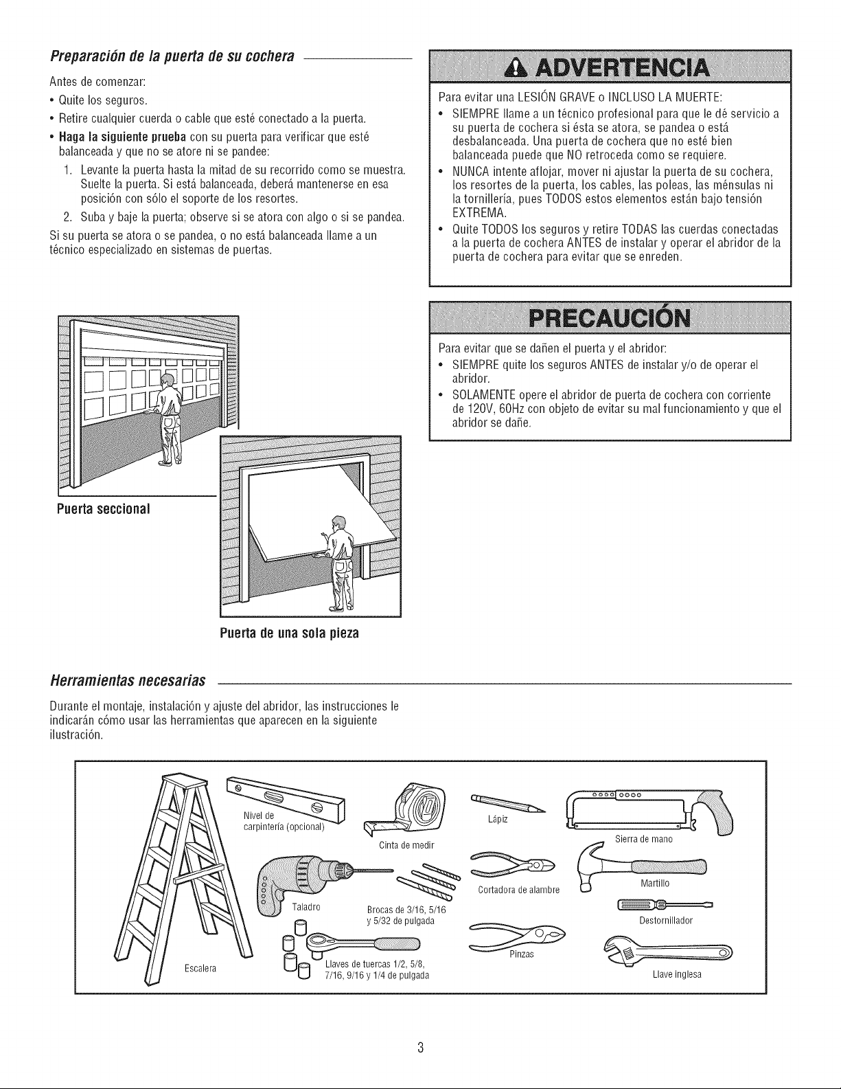
Preparaci6nde/a puerta de su cochem
Antes de comenzar:
• Quite los seguros.
• Retire cualquier cuerda o cable que est_ conectado a la puerta.
• Haga [a siguiente prueba con su puerta para verificar que est_
balanceaday que no se atore ni se pandee:
1. Levante la puerta hasta la mitad de su recorfido como se muestra.
Suelte la puerta. Si est6,balanceada,deber6,mantenerse en esa
posici6n con s6lo el soporte de los resortes.
2. Suba y baje la puerta; observe si se atora con algo o si se pandea.
Si su puerta se atora o se pandea, o no est6,balanceada[lame a un
t_cnico especializado en sistemas de puertas.
Para evitar una LESIONGRAVEo INCLUSOLA MUERTE:
• SIEMPRE Ilame a un t_cnico profesional para que le d_ servicio a
su puerta de cochera si _sta se atora, se pandea o est6,
desbalanceada. Una puerta de cochera que no est_ bien
balanceada puede que NO retroceda como se requiere.
• NUNCA intente aflojar, mover ni ajustar la puerta de su cochera,
los resortes de la puerta, los cables, las poleas, las m_nsulas ni
la tornillefia, pues TODOSestos elementos est6,nbajo tensi6n
EXTREMA.
• Quite TODOS los seguros y retire TODAS las cuerdas conectadas
a la puerta de cochera ANTES de instalar y operar el abridor de la
puerta de cochera para evitar que se enreden.
Para evitar que se daffen el puerta y el abfidor:
• SIEMPRE quite losseguros ANTESde instalar y/o de operar el
abridor.
• SOLAMENTEopere el abridor de puerta de cochera con corfiente
de 120V, 60Hz con objeto de evitar su mal funcionamiento y que el
abridor se daffe.
Puerta sectional
Puerta de una sola pieza
Herramientas necesafias
Durante el montaje, instalaci6n y ajuste del abridor, las instrucciones le
indicar6,nc6mo usar las herramientas que aparecen en la siguiente
ilustraci6n.
Escalera
Nivel de
carpinteria (opcional)
L_piz
Cinta de medir
Cortadora de alambre
de 3/16, 5/16
y 5/32 de pulgada
UO 7/16, 9/16 y 1/4 de pulga_Ja
Sierra de mano
Destornillador
Llave inglesa
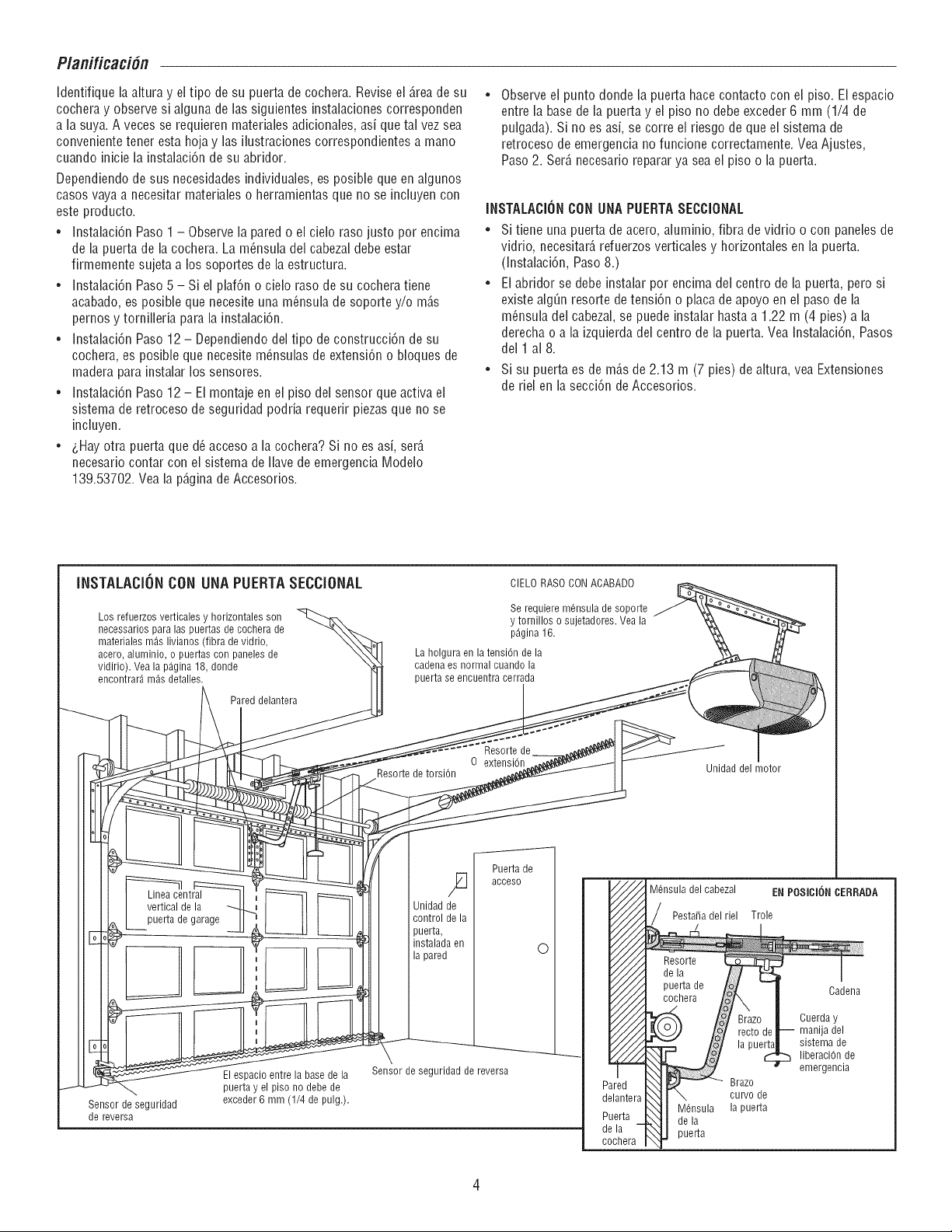
P/anificaci6n
Identifique la altura y el tipo de su puerta de cochera. Reviseel _,reade su
co@era y observe si alguna de las siguientes instalaciones corresponden
a la suya. A veces se requieren materiales adicionales, asi que tel vez sea
conveniente tener esta hoja y las Nustracionescorrespondientes a mano
cuando inicie la instaiaci6n de su abridor.
Dependiendo de sus necesidades individuaies, es posible que en algunos
casos vaya a necesitar materiales o herramientas que no se incluyen con
este producto.
• Instalaci6n Paso 1 - Observe la pared o el cielo raso justo por encima
de la puerta de la co@era. La m_nsula dei cabezal debe ester
firmemente sujeta a los soportes de la estructura.
• Instalaci6n Paso 5 - Si ei plaf6n o cielo raso de su cochera tiene
acabado, es posible que necesite una m_nsula de soporte y/o m_,s
pernos y torniiieria pare la instalaci6n.
• Instaiaci6n Paso 12 - Dependiendodei tipo de construcci6n de su
co@era, es posible que necesite m_nsulas de extensi6n o bloques de
madera pare instalar los sensores.
• Instalaci6n Paso 12 - El montaje en el piso del sensor que active el
sistema de retroceso de seguridad podria requerir piezas que no se
incluyen.
• _,Hayotra puerta que d_ acceso ala cochera? Si no es asi, ser_,
necesario contar con el sistema de Navede emergencia Modeio
139.53702. Vea la p6,ginade Accesorios.
Observe ei punto donde la puerta hace contacto con el piso. Elespacio
entre la base de la puerta y el piso no debe exceder 6 mm (1/4 de
pulgada). Si no es asi, se corre el riesgo de que el sistema de
retroceso de emergencia no funcione correctamente. Vea Ajustes,
Paso 2. Ser_,necesario reparar ya sea el piso o la puerta.
INSTALACiONCON UNA PUERTASECCiONAL
• Si tiene una puerta de acero, aluminio, fibre de vidrio o con paneles de
vidrio, necesitar_,refuerzos verticales y horizontales en la puerta.
(Instalaci6n, Paso8.)
• El abridor se debe instalar pot encima del centro de la puerta, pero si
existe alg0n resorte de tensi6n o place de apoyo en el paso de la
m_nsula del cabezal, se puede instalar haste a 1.22 m (4 pies) ala
derecha o ala izquierda dei centro de la puerta. Vea Instalaci6n, Pesos
del 1 al 8.
• Si su puerta es de m_,sde 2.13 m (7 pies) de altura, vea Extensiones
de riel en la secci6n de Accesorios.
INSTALACIONCONUNA PUERTASECCIONAL CIELO RASO CONACABADO
Los refuerzos verticales y horizontales son
necessarios pare las puertas de cochera de
materiales m_s livianos (libra de vidrio,
acero, aluminio, o puertas con paneles de
vidirio). Vea la p_.gina18, donde
encontrar_ m_s detalles.
Pared delantera
Se requiere m6nsula de soporte
y tornillos o sujetadores. Vea la
p_.gina16.
La holgura en la tensi6n de la
cadena es normal cuando la
puerta se encuentra cerrada
oe e,Se°nrtedes,0 . a dde,motor
Resorte d_ ......
Linea central
vertical de la
puerta de garage
Jnidad de
control de la
puerta,
instalada en
la pared
Puerta de
acceso
O
Sensor de seguridad
de reverse
El espacio entre la base de la
puerta y el piso no debe de
exceder 6 mm (1/4 de pulg.).
Sensor de seguridad de reverse
/_ M6nsula del cabezal EN POSICION CERRADA
c°cj I codeoo
V///A _--_ I°ol Brazo | Cuerday
_//////_ _/ rectodetJ manijadel
_/////_ _ /_/ lapuerta| sistemade
_ f_/ _ liberaciOn.de
Pared I :__ Brazo,
delantera _: ":1I \ curvode
, I' :_ I M6nsula la puerta
I_uer]:a--_ _ I dela
_era f _J puerta
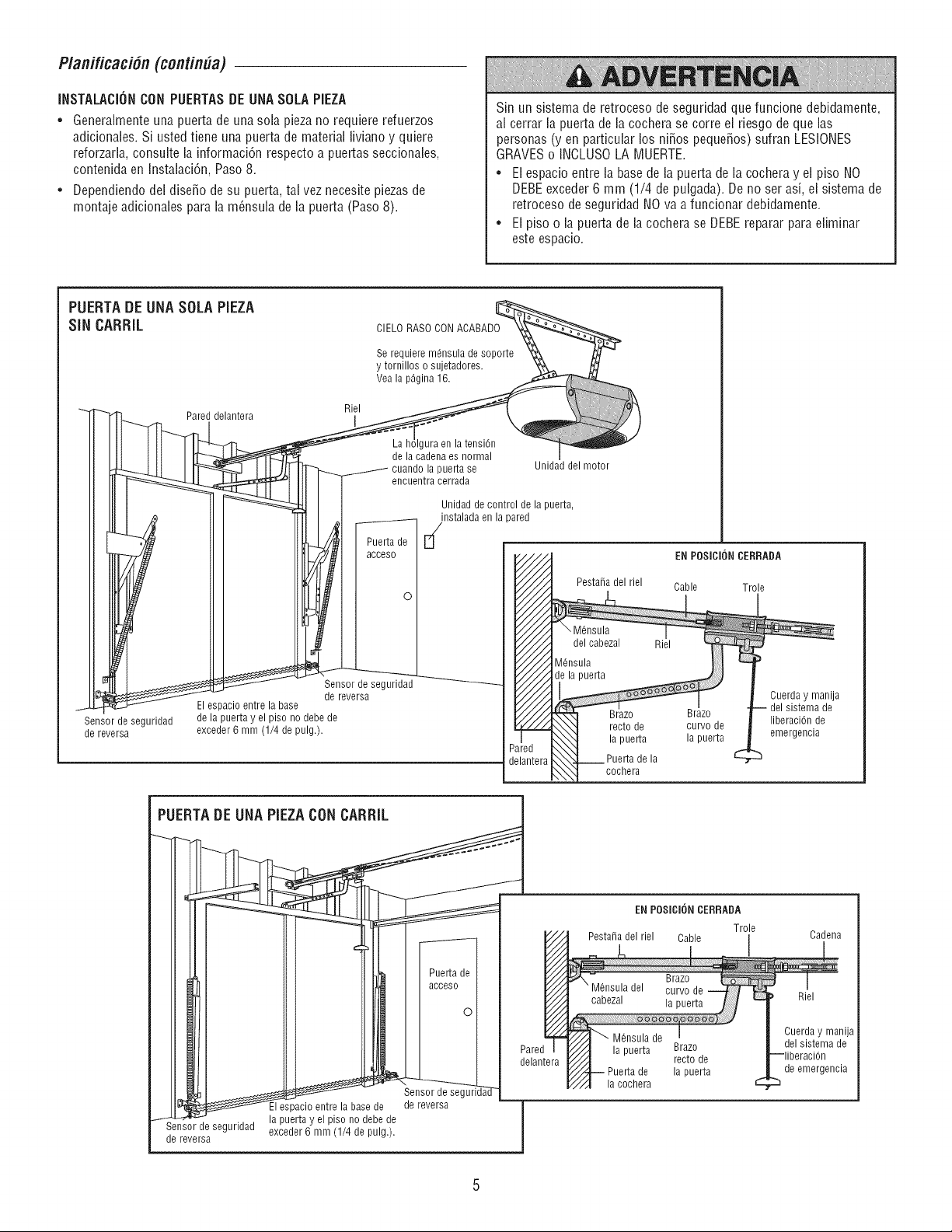
P/anificaci6n(continUa)
INSTALACIONCON PUERTASDE UNASOLA PIEZA
• Generalmente una puerta de una sola pieza no requiere refuerzos
adicionales. Si usted tiene una puerta de material liviano y quiere
reforzarla, consuite la informaci6n respecto a puertas seccionabs,
contenida en Instalaci6n, Paso 8.
• Dependiendo dei dise_o de su puerta, tal vez necesite piezas de
montaje adicionales para la m_nsula de la puerta (Paso 8).
Sin un sistema de retroceso de seguridad que funcione debidamente,
al cerrar la puerta de la cochera se corre el riesgo de que las
personas (yen particular los ni_os peque_os) sufran LESIONES
GRAVESo INCLUSOLA MUERTE.
• El espacio entre la basede la puerta de la cochera y el piso NO
DEBEexceder 6 mm (1/4 de pulgada). De no ser asi, el sistema de
retroceso de seguridad NO va a funcionar debidamente.
• El piso o la puerta de la cochera se DEBE reparar para eliminar
este espacio.
PUERTA DE UNA SOLA PIEZA __
SIN CARRIL CIELO RASO CONACABADO "k___
Se requiere m@sula de soporte X_ ,_ -
y tornillos o sujetadores. _,,_
Vea la p_gina 16.
Pared de_Riel
_a s_ Unidad del motor
II I e cuentracerra a
_-"'____ de control de la puerta,
Oo
--__ L!: F
Sensor de seguridad
de reversa
t El espacio entre la base
Sensor de seguridad de la puerta y el piso no debe de Brazo
de reversa exceder 6 mm (1/4 de pulg.), recto de
la puerta
Puerta de la
cochera
EN POSICIONCERRADA
Cable Trole
Brazo
curvo de
la puerta
Cuerda y manija
del sistema de
liberaciOn de
emergencia
_u _W _ Pealraenlera
_a y el piso no debe de
_,_,,rev,ersab_g...... exceder 6 mm (1/4 de pulg.). /
_1
EN POSICIONCERRADA
Trole
Pesta_a del riel Cable I
I
I
Brazo
recto de
la puerta
la cochera
Cadena
Riel
Cuerda y manija
del sistema de
de emergencia
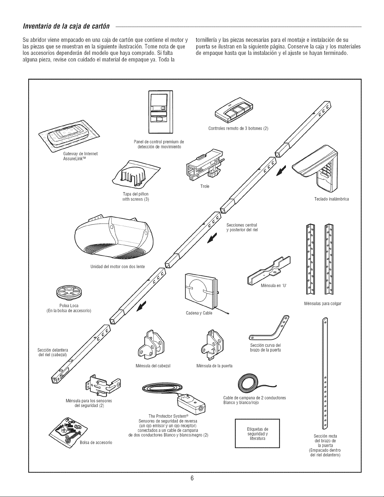
Inventario de la caja de cart#n
Su abridor viene empacado en una caja de cart6n que contiene el motor y
las piezasque se muestran en la siguiente ilustraci6n. Tome nota de que
los accesorios depender_,ndel modelo que haya comprado. Si falta
alguna pieza, revise con cuidado el material de empaque ya. Toda la
torniNeria y las piezas necesarias para el montaje e instalaci6n de su
puerta se ilustran en la siguiente p@ina. Conserve la caja y los materiales
de empaque hasta que la instalaci6n y el ajuste se hayan terminado.
GatewaydeInternet
AssureLinkTM
Panel de control premium de
detecci6n de movimiento
Tapa del piton
with screws (3)
0
Controles remoto de 3 botones (2)
Trole
Teclado inal_mbrica
@
Polea Loca
(En la bolsa de accesorio)
Unidad del motor con dos lente
Secci6ndelantera
del riel(cabezal)
M6nsula para los sensores
del seguridad (2)
Bolsa de accesorio
M6nsula del cabezal
@
M6nsula de la puerta
Sensores de seguridad de reversa
(un ojo emisory un ojo receptor)
conectados a un cable de campana
de dos conductores Blanco y blanco/negro (2)
Secciones central
y posterior del riel
SecciOncurva del
brazo de la puerta
@_._
Cable de campana de 2 conductores
Blanco y blanco/rojo
Etiquetas de
seguridad y
literatu ra
I,
d_
I,
I,
,%
%
M6nsulas para colgar
Secci6n recta
del brazo de
la puerta
(Empacado dentro
del riel delantero)
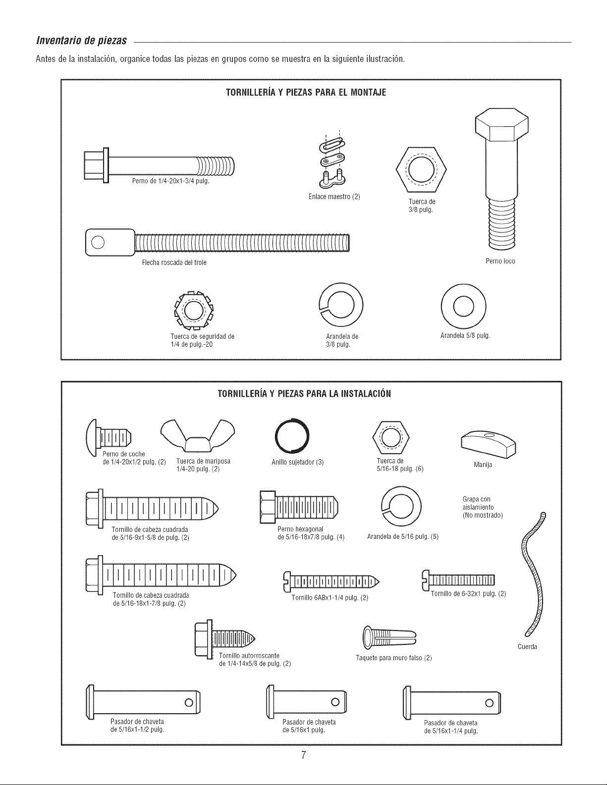
/nventario de piezas
Antes de la instalaci6n, organice todas las piezas en grupos como se muestra en la siguiente ilustraci6n.
TORNILLERiAY PIEZASPARAELIVIONTAJE
[©
Perno de 1/4-20xl-3/4 pulg.
Flecha roscada del trole
Enlace maestro (2)
Tuerca de
3/8 pulg.
Perno Ioco
Q
Tuerca de seguridad de
1/4 de pulg.-20
Arandela de
3/8 pulg.
Arandela 5/8 pulg.
TORNILLERiAY PIEZASPARALAINSTALACION
_oche
de 1/4-20xl/2 pulg.(2) Tuerca de mariposa
1/4-20 pulg.(2)
I lllllllll
de 5/16-9xl-5/8 de pulg. (2)
O
Anillo sujetador (3)
Perno hexagonal
de 5/16-18x7/8 pulg. (4)
Tuerca de
5/16-18 pulg. (6)
Arandela de 5/16 pulg. (5)
Tornillo de cabeza cuadrada
de 5/16-18xl-7/8 pulg. (2)
Tornillo 6ABx1-1/4 pulg. (2)
Manija
Tornillo autorroscante
de 1/4-14x5/8 de pulg. (2)
Taquete para muro falso (2)
Grapa con
aislamiento
(No mostrado)
lllllllllllllllllllll
Tornillo de 6-32xl pulg. (2)
Cuerda
Pasador de chaveta
de 5/16x1-1/2 pulg.
oi;
Pasador de chaveta
de 5/16xl pulg.
Pasador de chaveta
de 5/16x1-1/4 pulg.
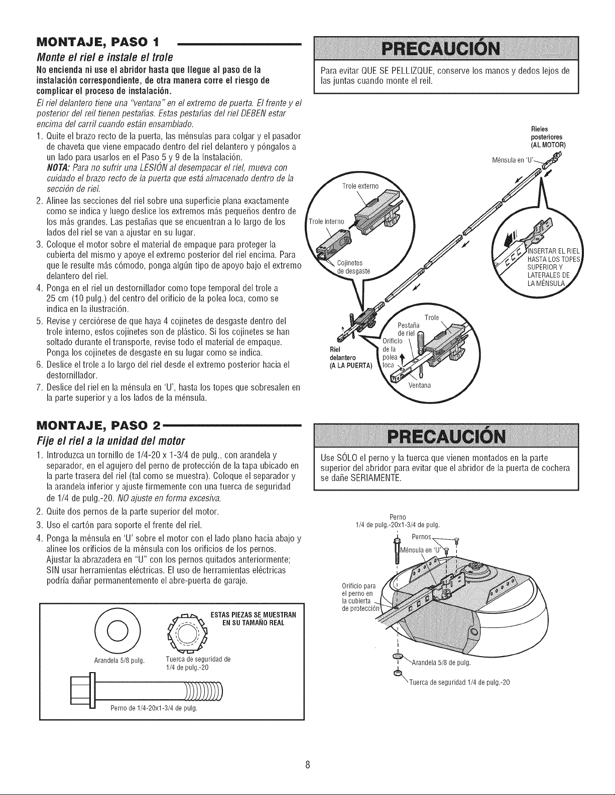
MONTAJE, PASO 1
Monte e/he/e inslale e/tro/e
No encienda ni use el abridor basraque Ileg.e al paso de la
instalaci6n correspondiente,de otra manera torte el riesgode
complicar el proceso de instalaci6n.
El riel delantero tiene una "ventana" en el extremo de puerta. El frente y el
posterior del reil tienen pestafias. Estas pest3fi3s del riel DEBENest3r
encim3 del carril cuando est_n ensambl3do.
1. Quite ei brazo recto de la puerta, las m(msulas para colgar y el pasador
de chavetaque viene empacado dentro del riei delantero y p6ngalos a
un lado para usarlos en ei Paso 5 y 9 de la Instalaci6n.
NOTA:Para no sufrir una LESIONal desempacar el riel, mueva con
cuidado el brazo recto de 13puert3 que est_ 31macenadodentro de 13
secci6n de rieL
2. Alinee las secciones dei riel sobre una superficie plana exactamente
como se indica y luego deslice los extremos mD,s peque_os dentro de
los mD.sgrandes. Las pesta_as que se encuentran a Io largo de los
lados del riel se van a ajustar en su lugar.
3. Coloque ei motor sobre ei material de empaque para proteger la
cubierta del mismo y apoye el extremo posterior dei riei encima. Para
que le resulte mD,s c6modo, ponga alg_n tipo de apoyo bajo el extremo
delantero del riel.
4. Ponga en el riel un destorniilador como tope temporal dei troie a
25 cm (10 pulg.) del centro del orificio de la polea Ioca, como se
indica en la ilustraci6n.
5. Revise y cerci6rese de que haya4 cojinetes de desgaste dentro del
trole interno, estos cojinetes son de plD.stico.Si los cojinetes se han
soltado durante ei transporte, revise todo ei material de empaque.
Ponga los cojinetes de desgaste en su lugar como se indica.
6. Deslice el troie a Io largo dei riel desde el extremo posterior hacia el
destornillador.
7. Deslice del riel en la m(msula en 'U', hasta los topes que sobresalen en
la parte superior y a los lados de la m_nsula.
Para evitar QUESE PELLIZQUE,conserve los manos y dedos lejos de
las juntas cuando monte el reil.
Rieles
posteriores
(AL MOTOR)
Trole externo
-role interno
ISERTAREL RIEL
HASTA LOSTOPES
\ Cojinetes SUPERIORY
desgaste LATERALESDE
f LA MENSULA
Trole
Pestafia \
Riel
delantero
(A LA PUERTA)
Ventana
MONTAJE, PASO 2
Fije el riel a la unidaddel motor
1. Introduzca un tornillo de 1/4-20 x 1-3/4 de pulg., con arandelay
separador, en el agujero del perno de protecci6n de latapa ubicado en
la partetrasera del riel (tal como se muestra). Coloque el separador y
la arandela inferior y ajuste firmemente con unatuerca de seguridad
de 1/4 de pulg.-20. NO 3juste en form3 excesiva.
2. Quite dos pernos de la parte superior del motor.
3. Uso el cart6n para soporte el frente dei riei.
4. Ponga la m(msula en 'U' sobre el motor con el lado piano hacia abajo y
alinee los orificios de la m(msula con los orificios de los pernos.
Ajustar ia abrazaderaen "U" con los pernos quitados anteriormente;
SiN usar herramientas el(_ctricas.El uso de herramientas ei(_ctricas
podfia daSar permanentemente el abre-puerta de garaje.
O ESTASPIEZASSE IVlUESTRAN
EN SUTAIVIAi(IOREAL
Arandela 5/8 pulg. Tuerca de seguridad de
1/4 de pulg.-20
_ Perno de 1/4-20xl-3/4 de pulg)_)
Use SOLO el perno y la tuerca que vienen montados en la parte
superior del abridor para evitar que ei abridor de la puerta de cochera
se dare SERIAMENTE.
Perno
1/4 de pulg.-2Oxl-3/4 de pulg.
M6nsula en
Orificio para
el perno en
la cubierta
I
_Arandela 5/8 de pulg.
_)L"Tuerca de seguridad 1/4 de pulg.-20
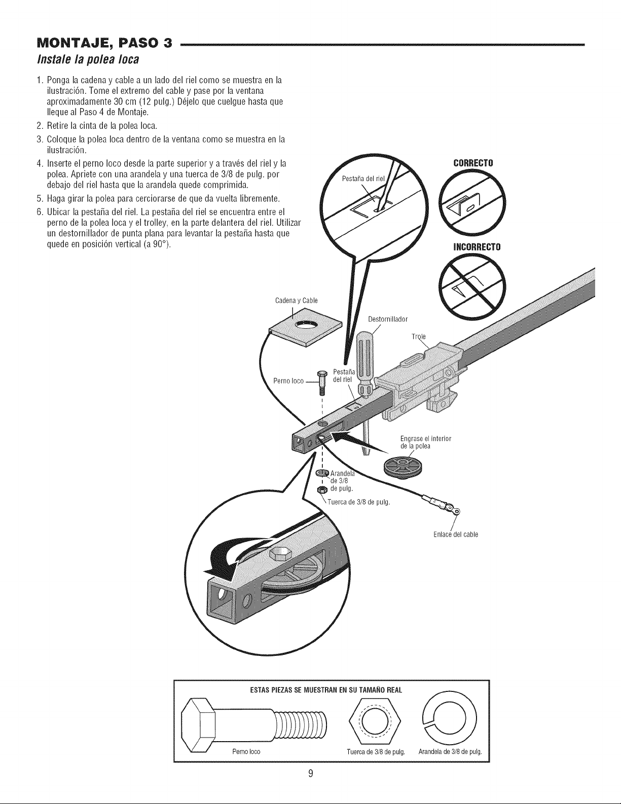
IViONTAJE PASO 3
/nsta/ela polea Ioca
1. Ponga la cadena y cable a un lado del riel como se muestra en la
ilustraci6n. Tome ei extremo del cable y pase pot la ventana
aproximadamente 30 cm (12 pulg.) D_jelo que cuelgue hasta que
Ileque al Paso 4 de Montaje.
2. Retire la cinta de la polea Ioca.
3. Coloque la polea Iocadentro de la ventana como se muestra en la
ilustraci6n.
4. Inserte el perno Ioco desde ia parte superior y a trav_s del riel y la
polea. Apriete con una arandela y una tuerca de 3/8 de pulg. pot
debajo del riel hasta que la arandelaquede comprimida.
5. Haga girar la polea para cerciorarse de que da vueita libremente.
6. Ubicar la pesta_a del riel. La pesta_a del riel se encuentra entre el
perno de la polea Ioca y el trolley, en la parte delantera del riel. Utilizar
un destornillador de punta plana para levantarla pesta_a hasta que
quede en posici6n vertical (a 90°).
Pesta_a del riel
CORRECTO
@
INCOFtRECTO
Cadena y Cable
Destornillador
Perno
Engraseel interior
de la polea
de pulg.
de 3/8 de pulg.
Enlace del cable
ESTAS PIEZAS SE IVIUESTRANEN SU TAIVlA_IOREAL
Perno Ioco Tuerca de 3/8 de pulg. Arandela de 3/8 de pulg,
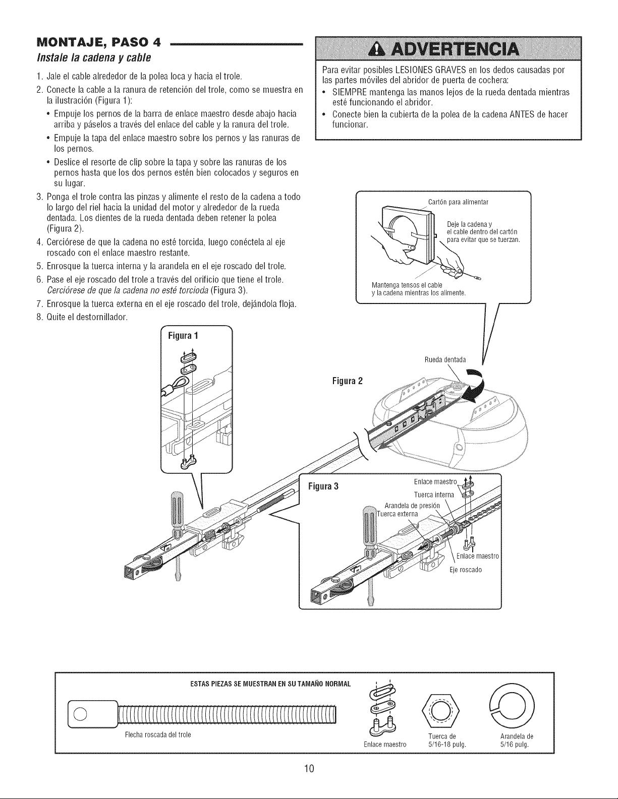
MONTAJE, PASO 4
Instale la cadenay cab/e
1. Jale el cable alrededor de la polea Ioca y hacia el trole.
2. Conecte la cable a la ranura de retenci6n del trole, como se muestra en
la ilustraci6n (Figura 1):
• Empuje los pernos de la barra de enlace maestro desde abajo hacia
arriba y p6,selosa trav(_sdel enlacedel cable y la ranura del trole.
• Empuje latapa del enlace maestro sobre los pernos y lasranuras de
los pernos.
• Deslice el resorte de clip sobre la tapa y sobre las ranuras de los
pernos hasta que los dos pernos est(m bien colocados y seguros en
su lugar.
3. Ponga el trole contra las pinzas y alimente el resto de la cadenaa todo
Io largo del riel hacia la unidad del motor y alrededor de la rueda
dentada. Los dientes de la rueda dentada deben retener la polea
(Figura 2).
4. Cerci6rese de que la cadena no est_ torcida, luegocon(_ctelaal eje
roscado con el enlace maestro restante.
5. Enrosque la tuerca interna y laarandela en el eje roscado del trole.
6. Pase el eje roscado del trole a trav_s del orificio que tiene el trole.
Cerci6resede que la cadena no estb torcioda (Figura3).
7. Enrosque la tuerca externa en el eje roscado del trole, dej6,ndolafioja.
8. Quite el destornillador.
Figura1
Para evitar posibles LESIONESGRAVESen los dedos causadaspor
las partes m6viles del abridor de puerta de cochera:
• SIEMPRE mantenga las manos lejosde la rueda dentada mientras
est_ funcionando el abridor.
• Conecte bien la cubierta de la polea de la cadenaANTES de hacer
funcionar.
Figura2
Cart6n para alimentar
____ De_ea_'aec_a y el ca rt6 n
ue se tuerzan.
Mantenga tensos el cable
y la cadena mientras los alimente.
Rueda dentada __
Figura3
/
Enlace maestro
Tuerca interna
Arandela de presi6n
externa
Eje roscado
[©
ESTAS PIEZASSE IVlUESTRANEN SU TAIVlA_IONORMAL
Flecha roscada del trole
Enlace maestro
Tuerca de
5/16-18 pulg.
Arandela de
5/16 pulg.
10
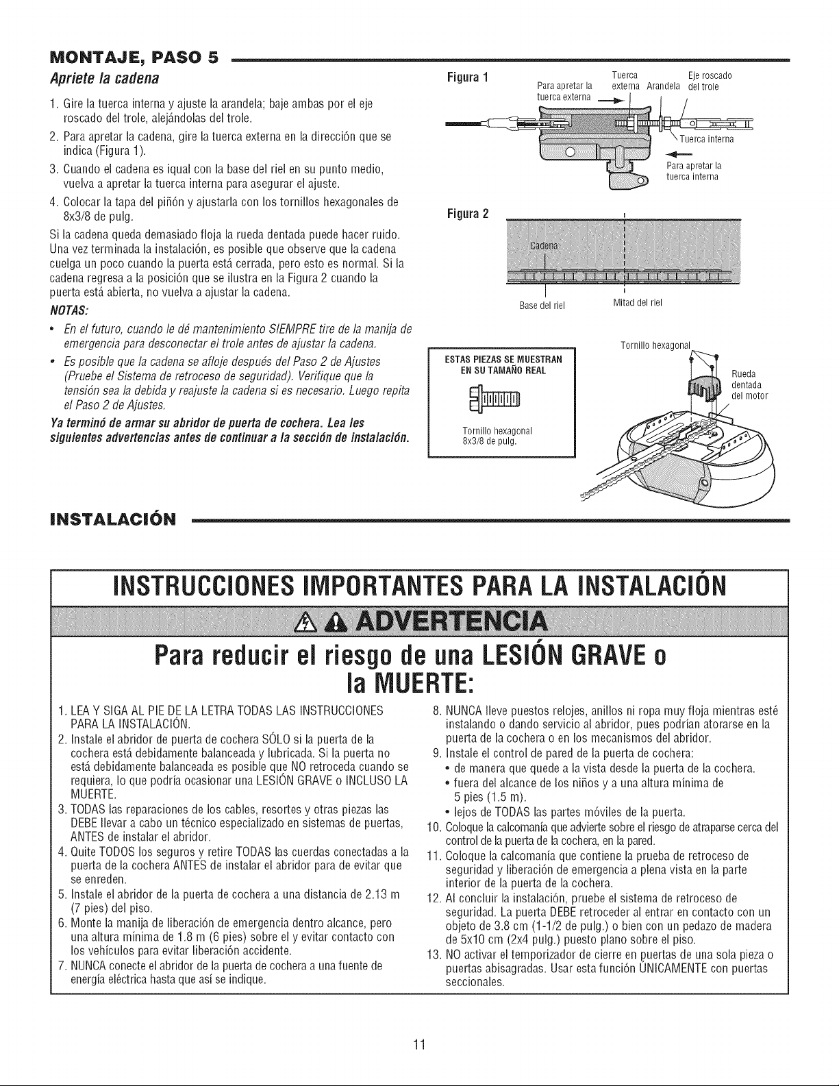
MONTAJE, PASO 5
Apriete/a cadena
1. Gire la tuerca interna y ajuste la arandela; baje ambas por el eje
roscado del trole, alej_,ndolasdel trole.
2. Para apretar la cadena, gire la tuerca externa en la direcci6n que se
indica (Figura 1).
3. Cuando el cadenaes iqual con la basedel riel en su punto medio,
vuelva a apretar la tuerca interna para asegurar el ajuste.
4. Colocar la tapa del pi_6n y ajustarla con los tornillos hexagonalesde
8x3/8 de pulg.
Si la cadenaqueda demasiado floja la rueda dentada puede hacer ruido.
Una vez terminada la instalaci6n, es posiNe que observe que la cadena
cuelga un poco cuando la puerta est,, cerrada, pero esto es normal. Si la
cadena regresa a la posici6n que se ilustra en la Figura 2 cuando la
puerta est,, abierta, no vuelva a ajustar la cadena.
NOTAS:
• En el futuro, cuando le d_ mantenimiento SIEMPRE tire de la manija de
emergencia para desconectar el trole antes de ajustar la cadena.
, Es posible que la cadena se afloje despubs del Paso 2 de Ajustes
(Pruebe el Sistema de retroceso de segufidad). Vefifique que la
tensiSn sea la debida y reajuste la cadena si es necesafio. Luego repita
el Paso2 de Ajustes.
Ya termin# de armar su abfidor de puerta de cocflera. Lea les
siguientes advertencias antes de continuara la secci#n de instalaci#n.
Figura1
Tuerca Eje roscado
Para apretar la externa Arandela del trole
tuerca externa
Figura2
Base del riel
ESTAS PIEZAS SE MUESTRAN
EN SUTAIVlA_IOREAL
Tornillo hexagonal
8x3/8 de pulg.
interna
Para apretar la
tuerca interna
Mitad del riel
Tornillo hexagonal
Rueda
dentada
del motor
INSTALACION
INSTRUCCIONESllVlPORTANTESPARALA INSTALACION
Para reducir el riesgo de una LESIONGRAVEo
la IVlUERTE:
1. LEAY SIGA AL PIE DE LA LETRATODASLAS INSTRUCCIONES
PARA LA INSTALACION.
2. Instaie el abridor de puerta de cochera SOLO si la puerta de la
cochera est,. debidamente balanceaday lubricada. Si ia puerta no
est,. debidamente balanceadaes posible que NO retroceda cuando se
requiera, Io que podria ocasionar una LESIONGRAVEo INCLUSOLA
MUERTE.
3. TODASlas reparaciones de los cables, resortes y otras piezas las
DEBEilevar a cabo un t_cnico especializado en sistemas de puertas,
ANTESde instalar el abridor.
4. Quite TODOSlos seguros y retire TODASlas cuerdas conectadas a la
puerta de la cochera ANTESde instalar el abridor para de evitar que
se enreden.
5. Instale el abridor de la puerta de cochera a una distancia de 2.13 m
(7 pies) del piso.
6. Monte la manija de liberaci6n de emergencia dentro alcance, pero
unaaltura minima de 1.8 m (6 pies) sobre el y evitar contacto con
los vehiculos paraevitar liberaci6n accidente.
7. NUNCAconecte el abridor de la puerta de cocheraa unafuente de
energia ei_ctricahasta que asi se indique.
8. NUNCAIleve puestos relojes, anillos ni ropa muy floja mientras est_
instalando o dando servicio al abridor, pues podrian atorarse en la
puerta de la cochera o en los mecanismos del abridor.
9. Instale ei control de pared de la puerta de cochera:
• de manera que quede a la vista desde la puerta de la cochera.
• fuera dei alcance de los ni_os y a una altura minima de
5 pies (1.5 m).
• lejos de TODASlas partes m6viles de la puerta.
10. Coloquelacalcomaniaqueadviertesobre el riesgode atraparsecercadel
control de lapuertade lacochera,en lapared.
11. Coloque la calcomania que contiene la prueba de retroceso de
seguridad y liberaci6n de emergencia a plena vista en la parte
interior de la puerta de la cochera.
12. AI concluir la instalaci6n, pruebe el sistema de retroceso de
seguridad. La puerta DEBEretroceder al entrar en contacto con un
objeto de 3.8 cm (1-1/2 de pulg.) o bien con un pedazode madera
de 5x10 cm (2x4 pulg.) puesto piano sobre ei piso.
13. NO activar eltemporizador de cierre en .puertasde una sola pieza o
puertas abisagradas. Usar esta funci6n UNICAMENTEcon puertas
seccionales.
11
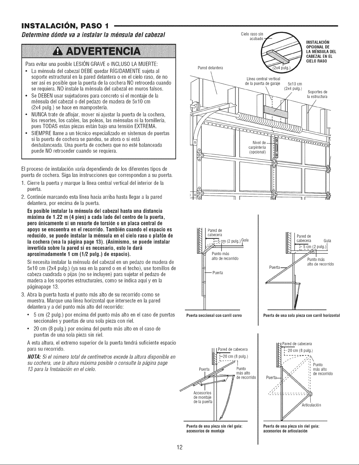
INSTALACION, PASO 1
Determined6ndeva a instalarla m nsulade/cabezal
Para evitar una posible LESIONGRAVEo INCLUSOLA MUERTE:
• La m_nsula del cabezalDEBEquedar RiGIDAMENTEsujeta al
soporte estructural en la pared delantera o en el cielo raso, de no
ser asi es posibb que la puerta de la cochera NO retroceda cuando
se requiera. NO instale la m_nsula del cabezal en muros falsos.
• Se DEBENusar sujetadores para concrete si el montaje de la
m_nsula del cabezalo del pedazode madera de 5x10 cm
(2x4 pulg.) se haceen mamposteda.
• NUNCAtrate de aflojar, mover ni ajustar la puerta de la cochera,
los resortes, los cables, las poieas, las m_nsuias ni la torniilefia,
puesTODAS estas piezasestD,n bajo una tensi6n EXTREMA.
• SIEMPRE Ilame a un t@nico especiaiizado en sistemas de puertas
si la puerta de cochera se pandea, se atora o si estD,
desbalanceada.Una puerta de cochera que no est_ balanceada
puede NO retroceder cuando se requiera.
El proceso de instahci6n vafia dependiendo de los diferentes tipos de
puerta de cochera. Siga las instrucciones que correspondan a su puerta.
1. Cierre la puerta y marque la Iinea central vertical del interior de la
puerta.
2. ContinUemarcando esta Iinea hacia arriba hasta Ilegar a la pared
dehntera, per encima de la puerta.
Espesible instalar la m_nsula del ¢abezal basra una distancia
m_xima de 1o22 m (4 pies} a ¢ada lade del centre de la puerta,
pete _nicamente si un reserte de tersi6n e un placa central de
apeye se encuentra en el recerride, Tambi_n cuande el espacie es
reducide, se puede instalar la m6nsula en el cieb rase e plaf6n de
la cochera(yea la p_gina page 13)o(Asimisme, se puede instalar
invertida sebre la pared si es necesafio, este le dar_
apreximadamente 1 cm (1/2 pulg,) de espacie),
Si necesita instaiar la m_nsula del cabezal en un pedazo de madera de
5x10 cm (2x4 pulg.) (ya sea en la pared o en el techo), use tornillos de
cabeza cuadrada o pijas (no se inciuyen) para sujetar ei pedazode
maderaa los soportes estructurabs, come se indica aqui y en la
p@inapage 13.
3. Abra la puerta hasta el punto mD,s alto de su recorrido come se
muestra. Marque una iinea horizontal que intersecte en la pared
delantera y a del punto mD,s alto del recorrido:
• 5 cm (2 pulg.) per encima del punto mD,s alto en el case de puertas
seccionales y puertas de una sola pieza con riei.
• 20 cm (8 pulg.) per encima del punto mD,s alto en el case de
puertas de una sola piezasin riel.
A esta altura, el extreme superior de la puerta tendrD,suficiente espacio
para su recorrido.
NOTA:Si el mimero total de centfmetros excede la altura disponible en
su cochera, use la altura mbxima posible o consulte la p@ina page
13 para la Instalaci6n en el cielo.
Pared delantera
Linea central vertical
de la puerta de garaje 5xl 0 cm
(2x4 pulg.)
INSTALACION
OPCIONALDE
LA MCNSULA DEL
CABEZALEN EL
CIELORASO
Soportes de
la estructura
Pared de
cabecera
Punto m_s
alto de recorrido
Puerta
Pnertaseccionalconcarrilcnrvo
Paredd
cabecera Guia
i_----
Punto m_s
alto de recorrido
T
Pnerta de nna sola pieza con carril horizontal
Puerta
Accesorios
de montaje
de la puerta
Pared de cabecera
1-20 cm (8 pulg.)
Punto
m6.salto
de recorrido
Pnerta de nna pieza sin riel gnia:
accesories de montaje
Pared de cabecera
,-20 cm (8 pulg.)
,- ', Punto
_, m_salto
" de recorrido
Pnerta de nna pieza sin riel gnia:
accesories de arlicnlaci6n
12
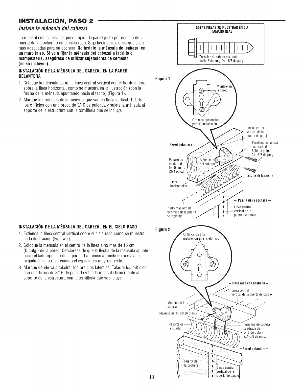
JNSTALACJON, PASO 2
/nsta/e /a m#,nsu/ade/cabeza/
La m6nsula del cabezalse puedefijar a la pared justo per encima de la
puerta de la cochera o en el cielo raso. Siga las instrucciones que sean
mAs adecuadaspara su cochera. No instaJeJam_nsuJadeJ cabezaJen
un mute false. Si va a fijar Ja m_nsuJadeJ cabezaJa JadriJlo o
mampostefia, aseg_rese de utiJizarsujetadoresde cemento
(no se incJuyen).
INSTALACIONDELA IVJENSULADELCABEZALENLA PARED
DELANTERA
1. Coloque la m_nsula sobre la finea central vertical con el borde inferior
sobre la linea horizontal, come se muestra en la ilustraci6n (con la
fiecha de la m_nsula apuntando hacia el techo) (Figura 1).
2. Marque los orificios de la m_nsula que van en finea vertical. Taladre
los orificios con una broca de 3/16 de pulgada y sujete la m_nsula al
soporte de la estructura con la tornillefia que se incluye.
Figura1
ESTASPIEZASSE P,'IUESTRANENSU
TAMA_IO REAL
Tornillos de cabezacuadrada
de 5/16 de pulg. 9xl-5/8 de pulg.
iNSTALACiONDELA MENSULADELCABEZALEN ELCIELORASO
1. Extienda la fineacentral vertical sobre el cielo raso come se muestra
en la ilustraci6n (Figura 2).
2. Coloque la m_nsula en el centre de la linea a no m_s de 15 cm
(6 pulg.) de la pared. Cerci6rese de que lafiecha de la m_nsula apunte
haciael lade opuesto de la pared. La m_nsula puede ser instalada
pegadaal cielo raso cuando el espacio es muy reducido.
3. Marque d6nde va a taladrar los orificios laterales. Taladre los orificios
con una broca de 3/16 de pulgada y fije la m_nsula firmemente al
soporte de la estructura con la tornilleria que se incluye.
-Pared delantera-
Pedazode
madera de
5x10 cm
(2x4 pulg.)
Linea
1
horizontales
/
1
I
Punto m4s alto del
recorrido de la puerta
de la garaje
Figura2
M6nsula del
cabezal "_-
M_ximo de 15 cm (6 pulg.)_
Resorte de-
la puerta
Linea central
vertical de la
puerta de garaje
Tornillos de cabeza
• cuadrada de
5/16 de pulg.-
9xl-5/8 de pulg.
Resortede lapuerta
- Puerta de la cechera -
Linea central
vertical de la
puerta de garaje
= Cieie rase con acabado =
_t_ Lineacentral
/_/ vertical de la puerta de garaje
Tornillosde cabeza
cuadradade
5/16depulg.-
9xl-5/8 depulg,
-Pared deiantera-
13
Linea central
vertical de la
puerta de garaje
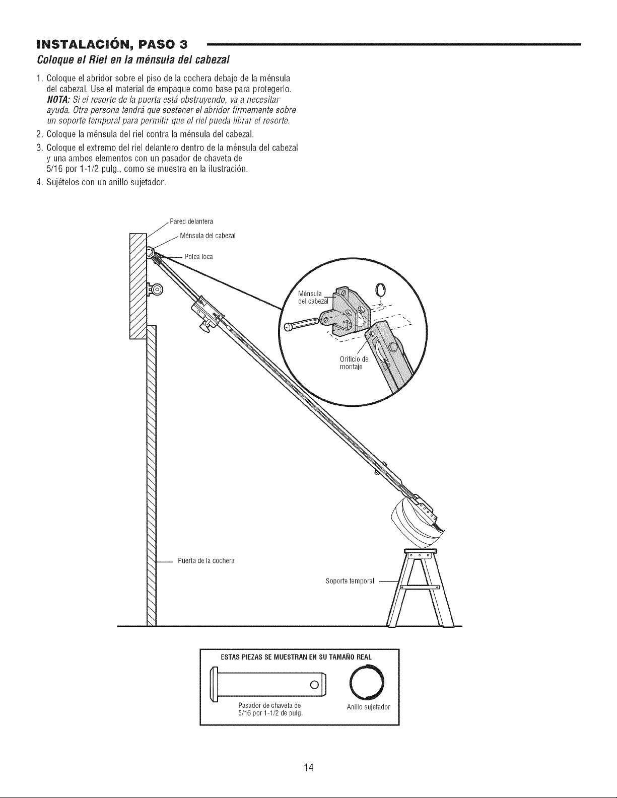
|NSTALAC|6N_ PASO :3
Coloqueel Riel en la m_nsula de/cabezal
1. Coloque el abridor sobre el piso de la co@era debajo de la m6nsula
del cabezal. Use el material de empaque como base para protegerlo.
NOTA:Si el resorte de la puerta estb obstruyendo, va a necesitar
ayuda. Otra persona tendr_ que sostener el abridor firmemente sobre
un soporte temporal para permitir que el riel pueda librar el resorte.
2. CoJoquela m_nsula del riel contra la m_nsula del cabezal.
3. Coloque el extremo del riel delantero dentro de la m_nsula del cabezal
y una ambos elementos con un pasador de chaveta de
5/16 por 1-1/2 pulg., como se muestra en la ilustraci6n.
4. Suj_telos con un anillo sujetador.
Pared delantera
M@sula del cabezal
Ioca
del
\
Orificio de
montaje
-- Puerta de la cochera
Soporte temporal --
ESTAS PIEZASSE iVIUESTRANEN SU TAIVIA_iOREAL
oD0
Pasador de chaveta de Anillo sujetador
5/16 por 1-1/2 de pulg.
14
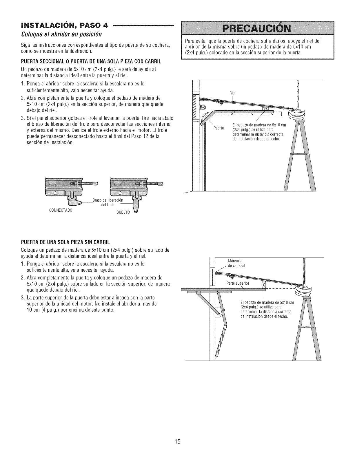
|NSTALAC|6N, PASO 4
Coloque el abfidor en posici6n
Siga las instrucciones correspondientes al tipo de puerta de su cochera,
como se muestra en la ilustraci6n.
PUERTASECCIONAL0 PUERTADE UNASOLA PIEZACON CARRIL
Un pedazode madera de 5x10 cm (2x4 pulg.) le ser_,de ayuda al
determinar la distancia ideal entre la puerta y el riel.
1. Ponga el abridor sobre la escalera; si la escalera no es Io
suficientemente alta, va a necesitar ayuda.
2. Abra completamente la puerta y coloque ei pedazode madera de
5x10 cm (2x4 pulg.) en la secci6n superior, de maneraque quede
debajo dei riei.
3. Si el panel superior golpea ei troie al levantar la puerta, tire hacia abajo
el brazo de liberaci6n del trole para desconectar ias secciones interna
y externa del mismo. Deslice el trole externo hacia el motor. Eltrole
puede permanecer desconectado hasta ei final del Paso12 de la
secci6n de Instalaci6n.
Para evitar que la puerta de cochera sufra da_os, apoye el riel del
abfidor de la misma sobre un pedazode madera de 5x10 cm
(2x4 pulg.) colocado en la secci6n superior de la puerta.
Riel
CONNECTADO
Brazo de liberaci6n
del trole
SUELTO
PUERTADE UNASOLA PiEZA SiN CARRiL
Coloque un pedazode madera de 5x10 cm (2x4 pulg.) sobre su ladode
ayuda ai determinar la distancia ideal entre la puerta y el riel.
1. Ponga ei abridor sobre la escaiera; si la escalera no es Io
suficientemente alta, va a necesitar ayuda.
2. Abra completamente la puerta y coioque un pedazode madera de
5x10 cm (2x4 pulg.) sobre su lado en la secci6n superior, de manera
que quede debajo del riel.
3. La parte superior de la puerta debe estar alineada con la parte
superior de la unidad dei motor. No instale ei abridor a m_,sde
10 cm (4 pulg.) por encima de este punto.
Mensula
de cabezal
El pedazo de madera de 5x10 cm
(2x4 pulg.) se utiliza para
determinar la distancia correcta
de instalaci6n desde el techo.
15
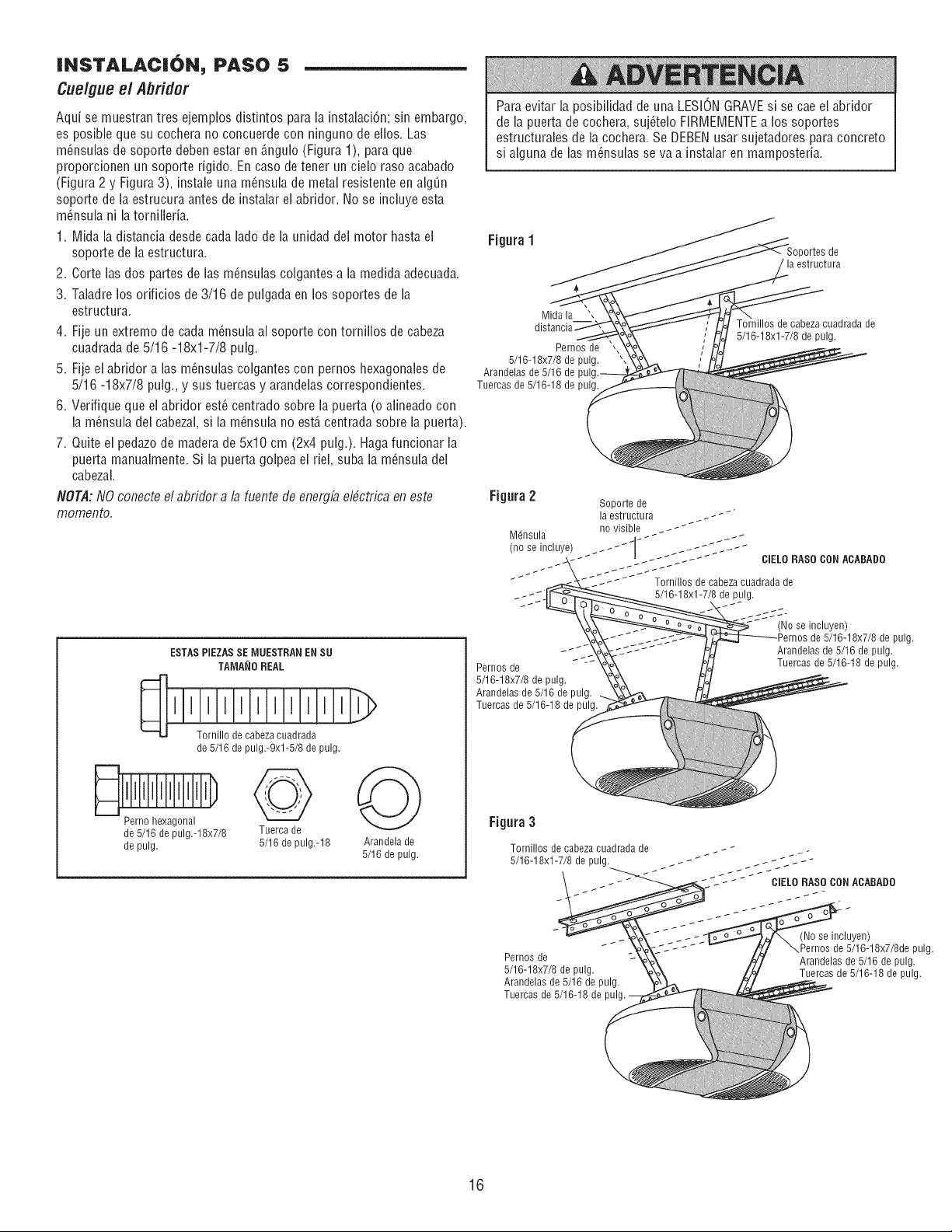
INSTALAC|ON, PASO 5
Cuelgueel Abridor
Aqui se muestran tres ejemplos distintos para la instalaci6n; sin embargo,
es posible que su cochera no concuerde con ninguno de eflos. Las
m_nsulas de soporte deben estar en _.ngulo(Figura 1), para que
proporcionen un soporte figido. En caso detener un cielo raso acabado
(Figura 2 y Figura 3), instale una m_nsula de metal resistente en algQn
soporte de la estrucura antes de instahr el abfidor. No se incluye esta
m_nsula ni latornillefia.
1. Mida ia distancia desde cada lado de la unidad del motor hasta el
soporte de la estructura.
2. Corte las dos partes de las m_nsulas colgantes a la medida adecuada.
3. Taladre los orificios de 3/16 de pulgada en los soportes de la
estructura.
4. Fije un extremo de cada m6nsula al soporte con tornillos de cabeza
cuadrada de 5/16 -18xl-7/8 pulg.
5. Fije el abridor alas m_nsulas colgantes con pernos hexagonales de
5/16 -18x7/8 pulg., y sus tuercas y arandelas correspondientes.
6. Verifique que ei abridor est_ centrado sobre la puerta (o alineado con
la m_nsula del cabezal, si la m_nsula no est,.centrada sobre la puerta).
7. Quite el pedazode madera de 5x10 cm (2x4 pulg.). Haga funcionar la
puerta manualmente. Si la puerta golpea el riel, suba la m_nsula dei
cabezal.
NOT,d: NOconecte el abridor a la fuente de energfael_ctrica en este
momento.
ESTAS PIEZASSE IVlUESTRANENSU
TAIVIA_IOREAL
de 5/16depulo.-9x1-5/8depulo.
de 5/16 de pulg.-18x7/8 Tuerca de
de pulg. 5/16 de pulg.-18
Arandela de
5/16 de pulg.
Para evitar la posibilidad de una LESIONGRAVEsi se cae el abridor
de la puerta de cochera, suj_telo FIRMEMENTEa los soportes
estructurales de la cochera. Se DEBENusar sujetadores para concreto
si alguna de las m_nsulas se va a instalar en mampostefia.
Figura1
)ortes de
Mida la ",
Pernos de
5/16-18x7/8 de pulg.
Arandelas de 5/16 de pul
Tuercas de 5/16-18 de pulg.
Tornillos de cabezacuadrada de
5/16-18xl-7/8 de pulg.
Figura2
Soporte de
la estructura _ _ __
Mensula no visible, .*_'_* _
(no se incluye) .... J7 _ _ .... _j_
jJ_" - .... LLL ..... CIELOBASe CON ACABADO
** ._ _--_-_ Tornillos de cabeza cuadrada de
.-_;Zl[- 0____ " 5/16-18xl-7/8 de pulg.
- (No se incluyen)
_o_ Pernos de 5/16-18x7/8 de pulg.
J-_ _o_ Arandelas de 5/16 de pulg.
Pernos de -- '_ Tuercas de 5/16-18 de pulg.
5/16-18x7/8 de pulg.
Arandelas de 5/16 de pulg.
Tuercas de 5/16-18 de pulg.
Figura 3
Tornillos de cabeza cuadrada de __. //_,_ _ _
5/16-18xl-7/8 de pulg. _ _
CIELO RASO CON ACABADO
Pernos de
5/16-18x7/8 de pulg.
Arandelas de 5/16 de pulg.
Tuercas de 5/16-18 de pul
(No se incluyen)
Pernos de 5/16-18x7/8de pulg.
Arandelas de 5/16 de pulg.
Tuercas de 5/16-18 de pulg.
16
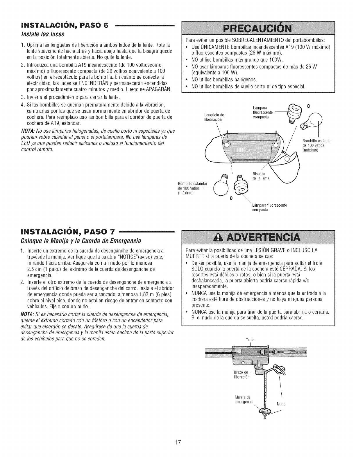
INSTALAC|ON, PASO 6
/nsta/e /as /uces
1. Optima las lengLietasde liberaci6n a ambos lados de la lente. Rote la
lente suavemente haciaatr6,sy hacia abajo hasta que la bisagra quede
en la posici6n totalmente abierta. No quite la lente.
2. Introduzca una bombilla A19 incandescente (de 100 voltioscomo
m6,ximo) o fiuorescente compacta (de 26 voltios equivalente a 100
voltios) en elrecept_.culopara la bombilla. En cuanto se conecte la
electricidad, las luces se ENCENDERANy permanecer6,nencendidas
por aproximadamente cuatro minutos y medio. Luego se APAGAR_,N.
3. Invierta el procedimiento para cerrar la lente.
4. Si las bombillas se queman prematuramente debido a la vibraci6n,
cambiarlas por las que se usan normalmente en abfidor de puerta de
cochera. Para reemplazo uso las bombilla para el abfidor de puerta de
cochera de A19, estandar.
NOTA: No use I_mparas halogenadas, de cueflo corto ni especialesya que
podrfan sobre calentar el panel o elportalbmpara. No use Ibmparas de
LED ya que pueden reducir elalcance o incluso el Mncionamiento del
control remoto.
Para evitar un posible SOBRECALENTAMIENTOdel portabombillas:
• Use UNICAMENTEbombillas incandescentesA19 (100 W m_ximo)
o fluorescentes compactas (26 W m_ximo).
• NO utiiice bombillas m6,sgrande que 100W.
• NO usar 16,mparasfluorescentes compactas de m6,sde 26 W
(equivalente a 100 W).
• NO utilice bombillas hal6genos.
• NO utilice bombillas de cuello cortoni de tipo especial.
L_.mpara
fluorescente --
Leng_eta de compacta
libearaci6n
/ Bombillo est_ndar
de 100 vatios
(m_ximo)
Bombillo est_.ndar
de 100 vatios --
(m_.ximo)
i Bisagra
@ @ de lalente
o
LAmparafluorescente
compacta
|NSTALAC|ON, PASO 7
Coloque la Manija y la Cuerda de Emergencia
1. Inserte un extremo de la cuerda de desenganchede emergencia a
trav_sde la manija. Verifique que la palabra "NOTICE"(aviso) este;
mirando hacia arriba. Asegurela con un nudo por Io menosa
2.5 cm (1 pulg.) del extremo de la cuerda de desenganche de
emergencia.
2. Inserte ei otro extremo de ia cuerda de desenganchede emergencia a
trav_s del orificio delbrazo de desenganche del carro. Instale el abridor
de emergencia donde pueda ser alcanzado, almenosa 1.83 m (6 pies)
sobre el nivel piso, donde no est_ en riesgo de entrar en contacto con
vehiculos. Fijelo con un nudo.
NOTA:Si es necesario cortar la cuerda de desenganchede emergencia,
queme el extremo cortado con un f6sforo o con un encendedorpara
evitar que elcord6n se desate. AsegLiresede que la cuerda de
desenganche de emergencia y la manija esten encima de 13parte superior
de los vehfculos para que no se enreden.
Para evitar la posibilidad de una LESIONGRAVEo INCLUSOLA
MUERTEsi la puerta de la cochera se cae:
• De ser posible, use la manija de emergencia para soltar el trole
SOLOcuando la puerta de la cochera est_ CERRADA.Si los
resortes est,. d(_bileso rotos, o bien si la puerta est6,
desbalanceada,la puerta abierta podda caerse r6,piday/o
inesperadamente.
• NUNCAuse la manija de emergencia a menos que la entradaa la
cochera est(_fibre de obstrucciones y no haya ninguna persona
presente.
• NUNCAuse la manija para tirar de la puerta paraabrirla o cerrarla.
Si el nudo de la cuerda se suelta, usted podda caerse.
Trole
Brazo de
liberaci6n
Manija de
emergencia Nudo
17
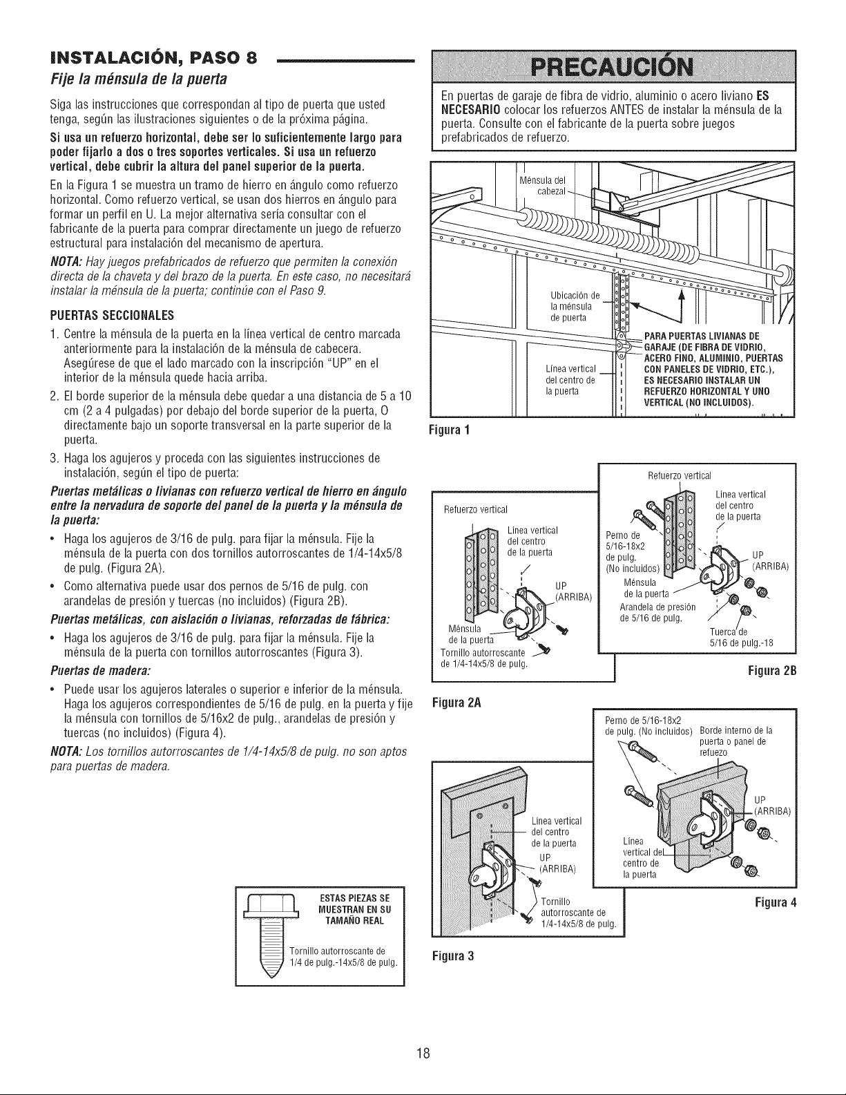
JNSTALACJON, PASO 8
Fije /a m_nsu/a de/a puerta
Siga las instrucciones que correspondan al tipo de puerta que usted
tonga, seg_n las ilustraciones siguientes o de la pr6xima p6,gina.
Si usa un refuerzohorizontal, debe set Io suficientemente Jargo para
poder fijarJo a dos o ires soportes verticaJesoSi usa un refuerzo
verticaJ,debe cubrir JaaJtura deJ paneJ superior de Ja puerta,
En la Figura 1 se muestra un tramo de hierro en _,ngulocomo refuerzo
horizontal. Como refuerzo vertical, se usan dos hierros en _,ngulopara
formar un perfil en U. La mejor alternativa soda consultar con el
fabricante de la puerta para comprar directamente un juego de refuerzo
estructural para instaiaci6n del mecanismo de apertura.
NOT,d: Hayjuegos prefabricados de refuerzo que permiten 13conexi6n
directa de la chaveta y del brazo de la puerta. En este caso, no necesit3r#
inst313r13m#nsul3 de 13puert3; continLie con el Paso 9.
PUERTASSECCiONALES
1. Centre ia m_nsuia de la puerta en la linea vertical de centro marcada
anteriormente para la instalaci6n de la m_nsuia de cabecera.
Aseg_resede que el lado marcado con ia inscripci6n "UP" en el
interior de la m_nsula quede hacia arriba.
2. El borde superior de la m_nsula debe quedar a una distancia de 5 a 10
cm (2 a 4 pulgadas) por debajo del borde superior de la puerta, O
directamente bajo un soporte transversal en la parte superior de la
puerta.
3. Haga los agujeros y proceda con las siguientes instrucciones de
instalaci6n, seg_n el tipo de puerta:
Puertas met_licas o livianas conrefuerzo vertical de flierro en _ngulo
entre la nervadura de soporte del panel de la puerta y la m_nsula de
la puerta:
• Haga los agujeros de 3/16 de pulg. para fijar la m_nsula. Fije la
m_nsula de la puerta con dos tornillos autorroscantes de 1/4-14x5/8
de pulg. (Figura 2A).
• Como alternativa puede usar dos pernos de 5/16 de pulg. con
arandelas de presi6n y tuercas (no inciuidos) (Figura 2B).
Puertas met_licas, con aislaci6n o livianas, reforzadas de f_brica:
• Haga los agujeros de 3/16 de pulg. para fijar la m_nsula. Fije la
m_nsula de la puerta con tornillos autorroscantes (Figura3).
Puertas de madera:
• Puede usar los agujeros lateraleso superior e inferior de la m_nsula.
Haga los agujeros correspondientes de 5/16 de pulg. en la puerta y fije
la m_nsula con torniilos de 5/16x2 de pulg., arandeias de presi6n y
tuercas (no incluidos) (Figura 4).
NOTA:Los tomillos autorrosc3ntes de 1/4-14x5/8 de pulg. no son 3ptos
par3 puert3s de mader3.
_4 ESTAS PIEZASSE
MUESTRAN EN SU
TAIVlANOREAL
rnillo autorroscante de
de pulg.-14x5/8 de pulg.
En puertas de garaje de fibra de vidrio, aluminio o acero liviano ES
NECESARIOcoiocar los refuerzos ANTESde instalar la m_nsula de la
puerta. Consuite con el fabricante de la puerta sobre juegos
prefabricados de refuerzo.
M@sula del
Lfnea vertical
del centro de
la puerta
__ PARA PUERTASLIVIANAS DE
GARAJE(DE EIBRA DEVIDRIO,
--ACERO FINO, ALUIVlINIO,PUERTAS
CONPANELESDE VIDRIO, ETC.),
ES NECESARIOINSTALARUN
REFUERZOHORIZONTALY UNO
VERTICAL(NO INCLUiOOS).
Figura1
Refuerzo vertical
Linea vertical
del centro
de la puerta
/
i
. ' UP
E,_(ARRIBA)
M nsula
de la puerta _ -
Tornillo autorroscante _
de 1/4-14x5/8 de pulg.
Figura2A
JJJJJJJJ
Figura3
Refuerzovertical
Perno de
5/16-18x2
de pulg.
(No incluidos',
Linea vertical
del centro
de la puerta
/
UP
M@sula
de la puerta
Arandela de presi6n
de 5/16 de pulg.
Tuerca/de
5/16 de pulg.-18
_IBA)
==j Figura2B
Linea vertical
del centro
de la puerta
UP
(ARRIBA)
Perno de 5/16-18x2
de pulg. (No incluidos) Borde interno de la
puerta o panel de
reluezo
Linea
vertical deL
centro de
la puerta
Tornillo
autorroscante de
1/4-14x5/8 de pulg. I
IBA)
Figura4
18
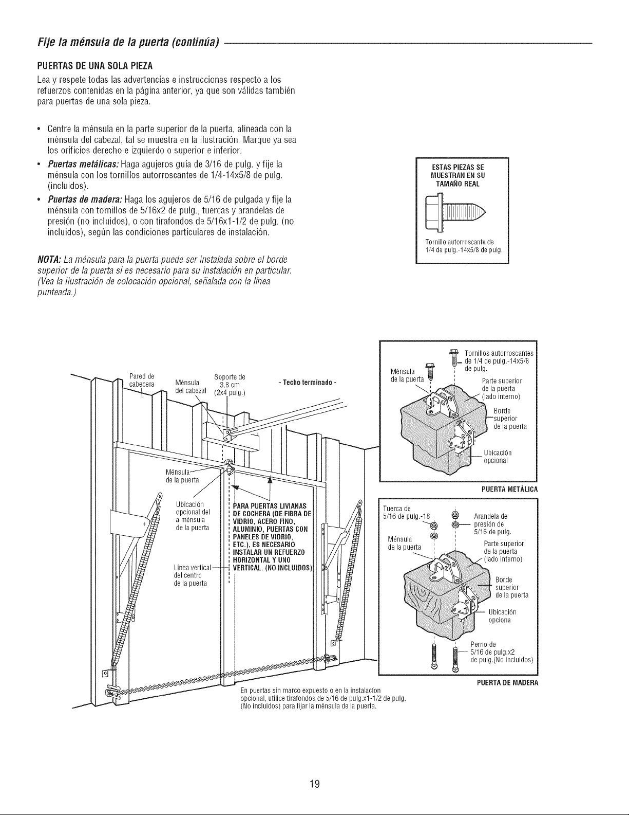
Fije la m_nsula de la puerta (contin#a)
PUERTASDEUNASOLA PIEZA
Lea y respetetodas las advertencias e instrucciones respecto a los
refuerzos contenidas en la pD,gina anterior, ya que son vDJidastambi_n
para puertas de una sola pieza.
• Centre la m_nsula en la parte superior de la puerta, alineadacon la
m_nsula del cabezal, tal se muestra en la ilustraci6n. Marque ya sea
los orificios derecho e izquierdo o superior e inferior.
• Puertas metd#icas: Haga agujeros guia de 3/16 de pulg. y fije la
m_nsula con los tornillos autorroscantes de 1/4-14x5/8 de pulg.
(incluidos).
• Puertas tie madera: Haga los agujeros de 5/16 de pulgada y fije la
m_nsula con tornillos de 5/16x2 de pulg., tuercas y arandelasde
presi6n (no incluidos), o con tirafondos de 5/16x1-1/2 de pulg. (no
incluidos), segOnlas condiciones particulares de instalaci6n.
NOTA:La mbnsula para la puerta puede ser instalada sobre el borde
superior de la puerta si es necesario para su instalaci6n en particular.
(Vea la ilustraci6n de colocaci6n opcional, sefialada con 13Ifnea
punteada.)
ESTAS PIEZASSE
[VlUESTRANEN SU
TAMANOREAL
Tornillo autorroscante de
1/4 de pulg.-14x5/8 de pulg.
Pared de Soporte de
cabecera M6nsula 3.8 cm
del cabezal pulg.)
de la puerta
Ubicaci6n
opcional del
a m6nsula
de la puerta
del centro
de la puerta
- Techo lerminado -
Tornillos autorroscantes
__ de 1/4 de pulg.-14x5/8
M6nsula _ _" de pulg.
de la puerta _, Parte superior
de la puerta
do interno)
Borde.
superior
, de la puerta
caci6n
ional
PUERTASLIVIANAS
DECOCRERA(DEFIBRA DE
VIDRIO, ACERORNO,
ALUMINIO, PUERTASCON
PANELESDE VlDRlO,
ETC.), ES NECESARIO
iNSTALARUN REFUERZO
HORIZONTALY UNO
VERTICAL.(NO INCLUIDOS
i
=
=
PUERTAMETALICA
Tuerca de
5/16 de pulg.-18
M6nsula ¢
de la puerta
Arandela de
_-- presi6n de
5/16 de pulg.
Parte superior
de la puerta
%_, ado interno)
:u°rdeer,or
_ de_a puerta
_ Ubicaci6n
_ opclona
.' Perno de
5/16 de pulg.x2
de pulg.(No incluidos)
PUERTADEMARERA
En puertas sin marco expuesto o en la instalacion
opcional, utilice tirafondos de 5/16 de pulg.xl-1/2 de pulg.
(No incluidos) para fijar la m6nsula de la puerta.
19
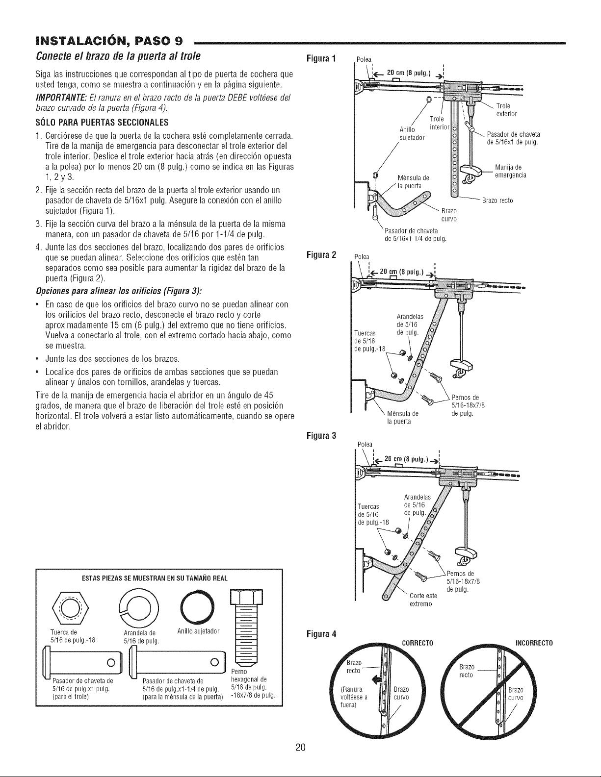
INSTALACION, PASO 9
Conecteel brazo de la puerta al trole
Siga las instrucciones que correspondan al tipo de puerta de cochera que
usted tenga, como se muestra a continuaci6n yen la p6,ginasiguiente.
IMPORTANTE"El ranura en el brazo recto de la puerta DEBE voltbese del
brazo curvado de la puerta (Figura 4).
SOLOPARAPUERTASSECCIONALES
1. Cerci6rese de que la puerta de la cochera est_ completamente cerrada.
Tire de la manija de emergencia para desconectar el trole exterior del
trole interior. Deslice el trole exterior hacia atr6,s(en direcci6n opuesta
a la polea) por Io menos 20 cm (8 pulg.) como se indica en las Figuras
1,2y3.
2. Fije la secci6n recta del brazo de la puerta al trole exterior usandoun
pasador de chaveta de 5/16xl pulg. Asegure la conexi6n con el anillo
sujetador (Figura 1).
3. Fije la secci6n curva del brazo a la m_nsula de la puerta de la misma
manera, con un pasador de chaveta de 5/16 por 1-1/4 de pulg.
4. Junte las dos secciones del brazo, Iocalizandodos pares de orificios
que se puedan alinear. Seleccionedos orificios que est_n tan
separados como sea posiNe para aumentar la rigidez del brazo de la
puerta (Figura 2).
Opciones para afinear los ofificies (Figura 3):
• En caso de que los orificios del brazo curvo no se puedan alinear con
los orificios del brazo recto, desconecte el brazo recto y corte
aproximadamente 15 cm (6 pulg.) del extremo que no tiene orificios.
Vuelva a conectarlo al trole, con el extremo cortado hacia abajo, como
se muestra.
• Junte las dos secciones de los brazos.
• Localice dos pares de ofificios de ambas secciones que se puedan
alinear y _nalos con tornillos, arandelas y tuercas.
Tire de la manija de emergencia hacia el abfidor en un 6,ngulode 45
grados, de manera que el brazo de fiberaci6n del trole est_ en posici6n
horizontal. Eltrole volver6,a estar listo autom6,ticamente,cuando se opere
el abridor.
ESTAS PIEZASSE IVIUESTRANENSU TAIVIA_IOREAL
Tuerca de
5/16 de pulg.-18
Paeadorde chavetade
5/16de pulg.xlpulg.
(paraeltrole)
Arandela de
5/16 de pulg.
O
Anillo sujetador
Pasador de chaveta de
5/16 de pulg.xl-1/4 de pulg.
(para la mensula de la puerta)
Perno
hexagonal de
5/16 de pulg.
-18x7/8 de pulg.
Figura1
Figura2
Figura 3
Figura 4
(
2O
Polea
20 cm (8 pulg.) .__,,
Brazo
curvo
de chaveta
de 5/16x1-1/4 de pulg.
Polea
I I
'_... 20 crn (8 pulg.) __
Arandelas /
de 5/16 /o_
Tuercas de pulg. /o/
de5/16 t /o/
de pulg.-18 \ /o/
la puerta
Arandelas
uercas de 5/16
de 5/16 de pulg.
de pulg.-18
Corte este
extremo
(Ranura
volteesea
CORRECTO
:Ul
/
Trole
exterior
Pasador de chaveta
de 5/16xl de pulg.
Manija de
emergencia
Brazo recto
_ Pernos de
5/16-18x7/8
de pulg.
SPernos de
5/16-18x7/8
depulg.
iNCORRECTO
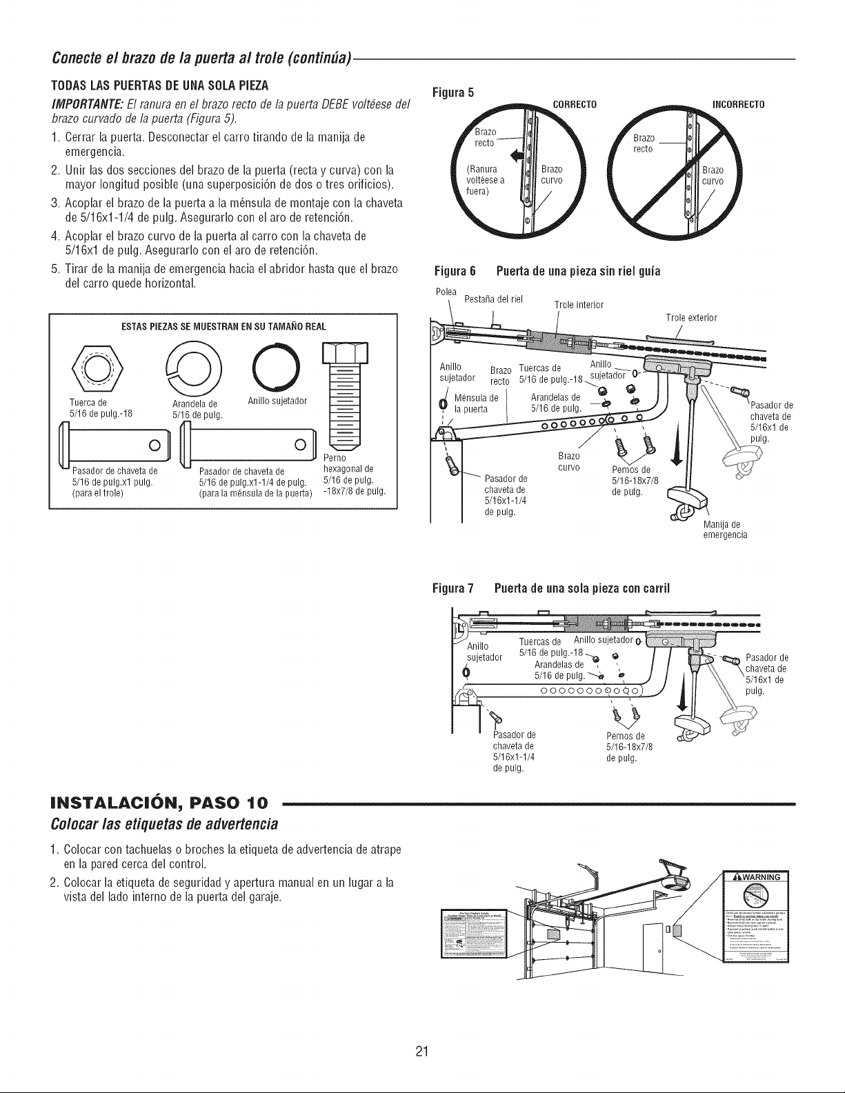
Conecte e/brazo de/a puerta al tro/e (contin#a)
TODASLAS PUERTASDEUHASOLA PiEZA
IMPORTANTE"El ranura en el brazo recto de la puerta DEBEvolt_ese del
brazo curvado de la puerta (Figura 5).
1. Cerrar la puerta. Desconectar el carro tirando de la manila de
emergencia.
2. Unir las dos secciones del brazo de la puerta (recta y curva) con la
mayor Iongitud posible (una superposici6n de dos o tres orificios).
3. Acoplar el brazo de la puerta a la m6nsula de montaje con la chaveta
de 5/16x1-1/4 de pulg. Asegurarlo con el aro de retenci6n.
4. Acoplar ei brazo curvo de la puerta al carro con ia chaveta de
5/16xl de pulg. Asegurarlo con el aro de retenci6n.
5. Tirar de la manila de emergencia hacia el abridor hasta que el brazo
dei carro quede horizontal.
ESTASPIEZASSE MUESTRANEN SU TAMA_IOREAL
Tuerca de
5/16 de pulg.-18
Pasadordechavetade
5/16de pulg.xlpulg.
(paraeltrole)
Arandela de
5/16 de pulg.
O
Anillo sujetador
ol
Pasador de chaveta de
5/16 de pulg.xl-1/4 de pulg.
(para la m6nsula de la puerta)
Perno
hexagonal de
5/16 de pulg.
-18x7/8 de pulg.
Figura5
(
CORRECT0
(Ranura 3r_ /
volt6esea "u_
/
Figura6 Puerta de aria pieza sin rieJguia
Polea
Pestafia del riel
Trole interior
Anillo Brazo Tuercas de Anillo
sujetador recto 5/16 de pulg.-18..._, jetad°r
_/ M6nsula de Arandelasde -_ _
la puerta 5/16 de pulg.
Pasador de
chaveta de
5/16xl -1/4
de pulg.
Brazo
curvo
Pernos de
5/16-18x7/8
de pulg.
Trole exterior
iNCORRECTO
--_Pasadorde
chaveta de
5/16xl de
pulg.
Manila de
emergencia
INSTALACi6N_ PASO IO
Colocar las etiquetas de advertencia
1. Colocar con tachuelas o broches la etiqueta de advertencia de atrape
en la pared cerca del control.
2. Colocar la etiqueta de seguridad y apertura manual en un lugar a la
vista del lado interno de la puerta dei garaje.
Figura7 Puerta de ariasola pieza concarriJ
chaveta de 5/16-18x7/8
5/16x1-1/4 de pulg.
de pulg.
21
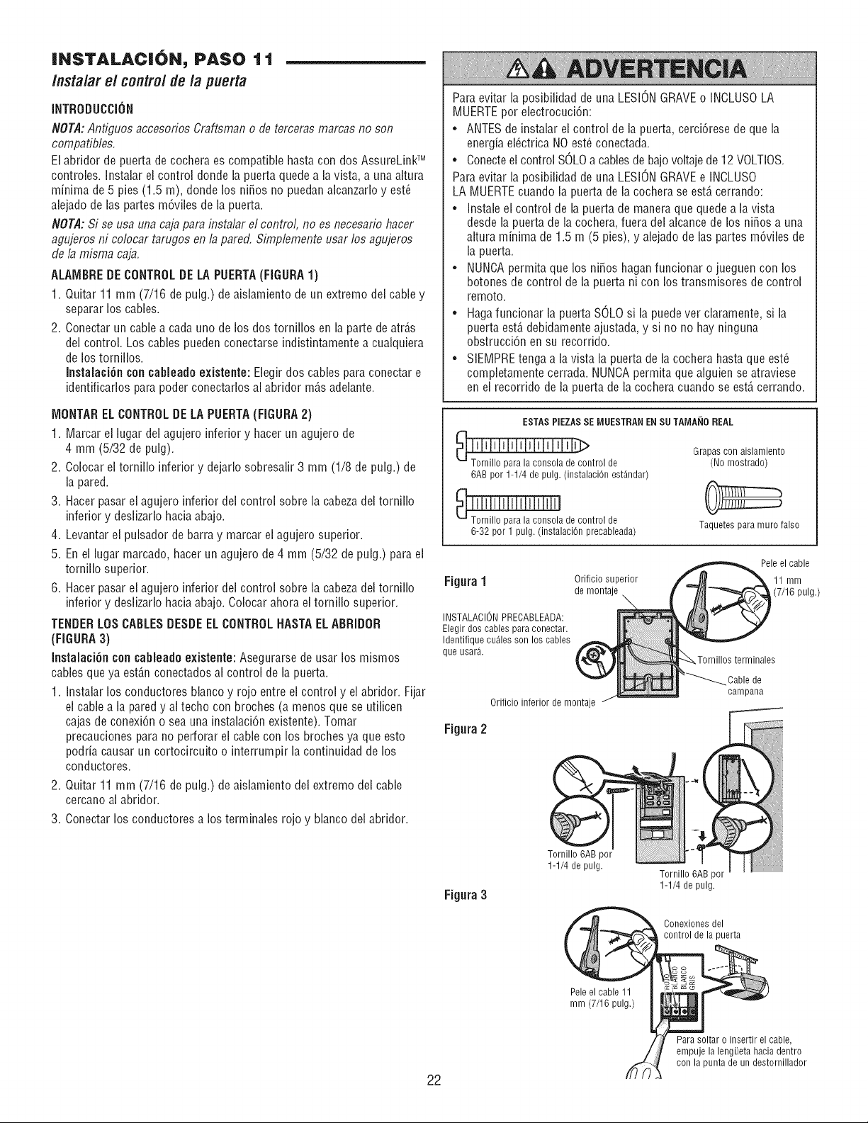
INSTALACION, PASO 1 1
Instalar el controlde la puerta
INTRODUCCION
NOTA:Antiguos accesorios Craftsman o de terceras mamas no son
compatibles,
El abridor de puerta de cochera es compatible hasta con dos AssureLinkTM
controles. Instalar ei control donde la puerta quede a la vista, a una aitura
minima de 5 pies (1.5 m), donde los ni_os no puedanalcanzarlo y est_
alejado de las partes m6viles de la puerta.
NOT,d: Si se usa una caja para instalar el control, no es necesafio hacer
agujeros ni colocar tarugos en la pared, Simplemente usar los agujeros
de la misma caja,
ALAIViBREDECONTROLDE LA PUERTA(FIGURA 1)
1. Quitar 11 mm (7/16 de pulg.) de aislamiento de un extremo del cable y
separar los cables.
2. Conectar un cable a cada uno de los dos tornillos en la parte de atr_,s
del control. Los cables pueden conectarse indistintamente a cualquiera
de los tornillos.
Instalaci6n concableado existente: Elegir dos cables para conectar e
identificarlos para poder conectarlos al abridor m_,sadelante.
IVIONTARELCONTROLDELA PUERTA(FIGURA 2)
1. Marcar el lugar del agujero inferior y hacer un agujero de
4 mm (5/32 de pulg).
2. Colocar el tornillo inferior y dejarlo sobresalir 3 mm (1/8 de pulg.) de
la pared.
3. Hacer pasar el agujero inferior del control sobre la cabezadel tornillo
inferior y deslizarlo hacia abajo.
4. Levantar el pulsador de barra y marcar el agujero superior.
5. En el lugar marcado, hacer un agujero de 4 mm (5/32 de pulg.) para el
torniilo superior.
6. Hacer pasar el agujero inferior del control sobre la cabezadei tornillo
inferior y desiizarlo hacia abajo. Colocar ahora el tornillo superior.
TENDERLOSCABLESDESDEELCONTROLNASTAELABRIDOR
(FiGURA 3)
Instalaci6n con cableadoexistente: Asegurarse de usar los mismos
cables que ya est_,nconectados al control de la puerta.
1. Instalar los conductores blanco y rojo entre el control y el abridor. Fijar
el cable a la pared y ai techo con broches (a menos que se utilicen
cajas de conexi6n o sea una instalaci6n existente). Tomar
precauciones para no perforar ei cable con los broches ya que esto
podfia causar un cortocircuito o interrumpir la continuidad de los
conductores.
2. Quitar 11 mm (7/16 de pulg.) de aislamiento del extremo del cable
cercano al abridor.
3. Conectar los conductores a los terminales rojo y blanco del abridor.
Para evitar la posibilidad de una LESIONGRAVEo INCLUSOLA
MUERTEpor electrocuci6n:
• ANTESde instalar el control de la puerta, cerci6rese de que la
energia el_ctrica NO est_ conectada.
• Conecteel control SOLOa cables de bajovoltaje de12 VOLTIOS.
Para evitar la posibilidad de una LESIONGRAVEe INCLUSO
LA MUERTEcuando la puerta de la cochera se est,, cerrando:
• Instale el control de la puerta de manera que quede a la vista
desde la puerta de la cochera, fuera del alcance de los ni_os a una
altura minima de 1.5 m (5 pies), y alejado de las partes m6viles de
la puerta.
• NUNCApermita que los ni_os haganfuncionar o jueguen con los
botones de control de la puerta ni con los transmisores de control
remoto.
• Haga funcionar la puerta SOLO si la puedever claramente, si la
puerta est,, debidamente ajustada, y si no no hay ninguna
obstrucci6n en su recorfido.
• SIEMPREtenga a la vista la puerta de la cochera hasta que est_
completamente cerrada. NUNCApermita que alguien se atraviese
en el recorrido de la puerta de la cochera cuando se est,. cerrando.
ESTAS PIEZASSE MUESTRAN EN SUTAMA_IO REAL
_ntrol de
6AB por 1-1/4 de pulg. (instalaci6n est_ndar)
111111111111111
paralaconsoladecontrolde
6-32porf pulg.(instalaci6nprecableada
Grapas con aislamiento
(No mostrado)
Taquetes para muro falso
Figura1
INSTALACION PRECABLEADA:
Elegir dos cables para conectar.
Identifique curies son los cables
que usarg.
Orificio inferior de montaje
Orificio superior
de montaje
\
Pele el cable
11 mm
(7/16 pulg.)
Tornillos terminales
_Cable de
campana
Figura2
Figura 3
1-1/4 de pulg.
Tornillo 6AB por
1-1/4 de pulg.
Conexiones del
control puerta
Pele el cable 11
mm (7/16 pulg.)
22
Para soltar o insertir el cable,
empuje la leng_eta hacia dentro
con la punta de un destornillador
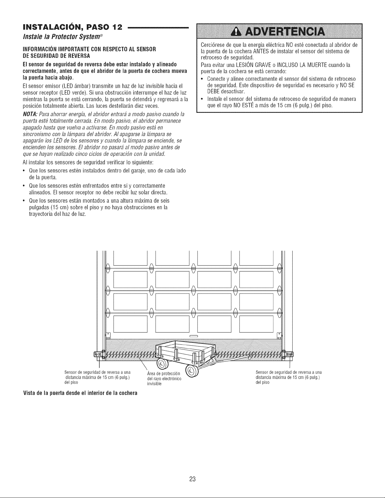
INSTALACi6N, PASO 12
Instale la Protector System®
INFORiVlACiONliVIPORTANTECON RESPECTOAL SENSOR
DESEGURiDAD DE REVERSA
Ei sensor de segufidad de reversa debe estar instaiado y aiineado
correctamente, antes de que el abridor de la puerta de cochera rnueva
la puerta hacia abajo,
El sensor emisor (LED6,mbar)transmite un haz de luz invisible hacia el
sensor receptor (LEDverde). Si una obstrucci6n interrumpe el haz de luz
mientras la puerta se est6,cerrando, ia puerta se detendr6,y regresar6,a la
posici6n totaimente abierta. Las luces destellar6,ndiez veces.
NOT,d: Para ahorrar energfa,el abridor entrar# a modo pasivo cuando la
puerta est# totalmente cerrada. En modo pasivo, el abridor permanece
apagado hasta que vuelva a acfivarse. En modo pasivo est# en
sincronismo con la I#mpara del abridor. AI apagarse la I#mpara se
apagar#n los LED de los sensores y cuando la I#mpara se enciende, se
encienden los sensores. El abridor no pasar# al modo pasivo antes de
que se hayan realizado cinco ciclos de operaci6n con 13unidad.
AI instalar los sensores de seguridad verificar Io siguiente:
• Que los sensores est_n instalados dentro del garaje, uno de cada lado
de la puerta.
= Que los sensores est_n enfrentados entre si y correctamente
alineados. El sensor receptor no debe recibir luz solar directa.
• Que los sensores est6,nmontados a una altura m_xima de seis
pulgadas (15 cm) sobre el piso y no haya obstrucciones en la
trayectoria del haz de luz.
Cerci6rese de que la energia ei_ctrica NO est_ conectadaai abridor de
la puerta de la cochera ANTES de instalar el sensor del sistema de
retroceso de seguridad.
Para evitar una LESIONGRAVEo INCLUSOLA MUERTEcuando la
puerta de la cochera se est6,cerrando:
• Conecte y alinee correctamente el sensor dei sistema de retroceso
de seguridad. Este dispositivo de seguridad es necesario y NO SE
DEBEdesactivar.
• Instale el sensor del sistema de retroceso de seguridad de manera
que el rayo NO ESTEa m6,sde 15 cm (6 pulg.) del piso.
Sensor de seguridad de reversa a una
distancia maxima de 15 cm (6 pulg.)
del piso
Vista de la puerta desde el interior de la cochera
Area de protecci6n
del rayo electrOnico
invisible
Sensor de seguridad de reversa a una
distancia maxima de 15 cm (6 pulg.)
del piso
23
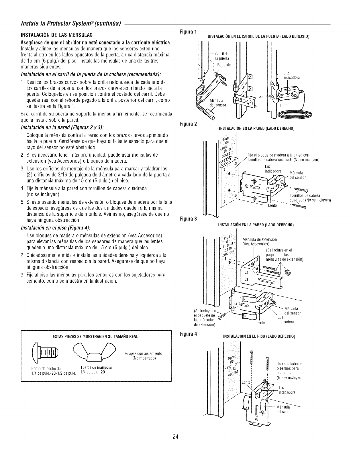
/nstale /a Protector System®(contin#a)
INSTALACiONDE LAS MleNSULAS
Aseg_resede que el abfidor no est_ conectadoa ia corfiente ei_ctfica.
Instale y aNneelas m_nsulas de manera que los sensores est_n uno
frente al otro en los lades opuestos de la puerta, a una distancia m_,xima
de 15 cm (6 pulg.) del piso. Instale las m_nsulas de una de las tres
maneras siguientes:
Instalaci6n en el carril de la puerta de la cochera (recomendada):
1. Deslice los brazes curves sobre la orilla redondeadade cada uno de
los carriles de la puerta, con los brazes curves apuntando hacia la
puerta. Col6quelos en su posici6n contra el costado del carril. Debe
quedar ras, con el reborde pegado a la oriNaposterior del carril, come
se ilustra en la Figura 1.
Si el carril de su puerta no soporta la m_nsulafirmemente, se recomienda
que la instale sobre la pared.
Instalacidn en la pared (Figuras 2 y 3):
1. Coloque la m_nsula contra la pared con los brazes curves apuntando
hacia la puerta. Cerci6rese de que haya suficiente espacio para que el
rayo del sensor no est_ obstruido.
2. Si es necesafio tenet m_,sprofundidad, puede usar m_nsulas de
extensi6n (veaAccesorios) o bloques de madera.
3. Use los orificios de montaje de la m_nsula para marcar y taladrar los
(2) orificios de 3/16 de pulgada de di_,metroa cada lade de la puerta a
una distancia m_xima de 15 cm (6 pulg.) del piso.
4. Fije la m_nsula a la pared con torniNos de cabezacuadrada
(no se incluyen).
5. Si est,, usando m_nsulas de extensi6n o bloques de madera per lafalta
de espacio, aseg_rese de que ias dos unidades queden a la misma
distancia de ia superficie de montaje. Asimismo, aseg_resede que no
haya ninguna obstrucci6n.
Instalaci6n en el pise (Figura 4):
1. Use bioques de madera o m_nsulas de extensi6n (vea Accesorios)
para eievar las m_nsulas de los sensores de manera que las lentes
queden a una distancia m_,ximade 15 cm (6 pulg.) dei piso.
2. Cuidadosamente mida e instale las unidades derecha y izquierda a la
misma distancia con respecto a la pared. Aseg_rese de que no haya
ninguna obstrucci6n.
3. Fije al piso las m_nsulas para los sensores con los sujetadores para
cemento, come se muestra en la ilustraci6n.
ESTASPIEZASSE IVlUESTRANENSU TAMA_IDREAL
Perno de coche de
1/4 de pulg.-20xt/2 de pulg.
Tuerca de mariposa
1/4 de pulg.-20
Grapas con aislamiento
(No mostrado)
Figura1
INSTALACI6N EN ELCARRIL DE LA PUERTA(LADe DERECNO)
Carril de
la puerta
Reborde
i
M6nsula
sensor
Figura2
Figura 3
INSTALACION ENLA PARED(LADe DERECRO}
Luz
indicadora
el
iri_
be
y.
J
(Se incluye en ..
el paquete de
las m6nsulas
de extensi6n)
Fije el bloque de madera a la pared con
cabeza cuadrada (No se incluyen)
Luz
indicadora M6nsula
sensor
Tornillos de cabeza
...... cuadrada (No se incluyen)
Lente ---"_
Figura4
INSTALACI6N EN LA PARED (LADe DERECND)
M6nsula de extensi6n
!_ (Vea Accesorios)
(Se incluye en el
I I _'1 paquete de las
_-_--_ /'_/J I rn6nsulas de extensi6n)
Lente indicadora
INSTALACION ENEL PISO (LADO DERECRO)
J
i _ Use sujetadores
_ _ o pernos para
, concrete
i
(No se incluyen)
Luz
indicadora
24
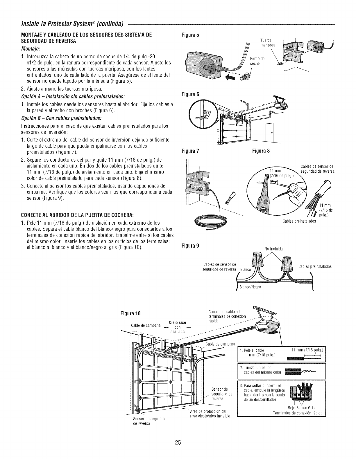
/nstale /a ProtectorSystem®(continUa)
IVIONTAJEY CABLEADODE LOSSENSORESDESSISTEIVlADE
SEGURIDADDE REVERSA
Montaje:
1. Introduzca la cabezade un perno de coche de 1/4 de pulg.-20
xl/2 de pulg. en la ranura correspondiente de cada sensor. Ajuste los
sensores alas m_nsulas con tuercas mariposa, con los lentes
enfrentados, uno de cada lade de la puerta. AsegQresede el lente del
sensor no quede tapado per la m_nsula (Figura 5).
2. Ajuste a mane lastuercas mariposa.
Opci6n A - Instalaci6n sin cables preinstalades:
1. Instale los cables desde los sensores hasta el abridor. Fije los cables a
la pared y el techo con broches (Figura 6).
Opcifin B - Con cables preinstalades:
Instrucciones parael case de que existan cables preinstalados para los
sensores de inversiCn:
1. Corte el extreme del cable del sensor de inversiCn dejando suficiente
largo de cable para que pueda empalmarse con los cables
preinstalados (Figura 7).
2. Separe los conductores del par y quite 11 mm (7/16 de pulg.) de
aislamiento en cada uno. En dos de los cables preinstalados quite
11 mm (7/16 de pulg.) de aislamiento en cada uno. Elija el mismo
color de cable preinstalado para cada sensor (Figura 8).
3. Conecte al sensor los cables preinstalados, usando capuchones de
empalme. Verifique que los colores sean los que correspondan a cada
sensor (Figura 9).
CONECTEAL ABRIDORDE LA PUERTADECOCHERA:
1. Pele 11 mm (7/16 de pulg.) de aislaciCn en cada extreme de los
cables. Separa el cable blanco del blanco/negro para conectarlos a los
terminales de conexiCn r_,pidadel abridor. Empalme entre si los cables
del mismo color. Inserte los cables en los orificios de los terminales:
el blanco al blanco y el blanco/negro al gris (Figura 10).
Figura5
Tue!ca [_
marlposa
_ _nh°ede
Figura B
i
Figura7 Figura8
Cables de sensor de
seguridad de reversa
11 mm
(7/16 de
pulg.)
Cables preinstalados
Figura9
No incluida
Cables de sensor de
seguridad de reversa Cables preinstalados
Figura 10
Cielo raso
Cable de campana = con
Conecte el cable a las
terminales de conexiCn
r_pida
Sensor de seguridad
de reversa
Sensor de
seguridad de
reversa
,_rea de protecciCn del
rayo electrCnico invisible
1. Pele el cable 11 mm
11 mm (7/16 pulg.) _ _)
2. Tuerza juntos los
[ cab es de m smo co or
3. Para soltar o insertir el
cable, empuje la leng_eta
hacia dentro con la punta
de un destornillador
Rojo Blanco Gris
Terminales de conexiCn r_pida
25
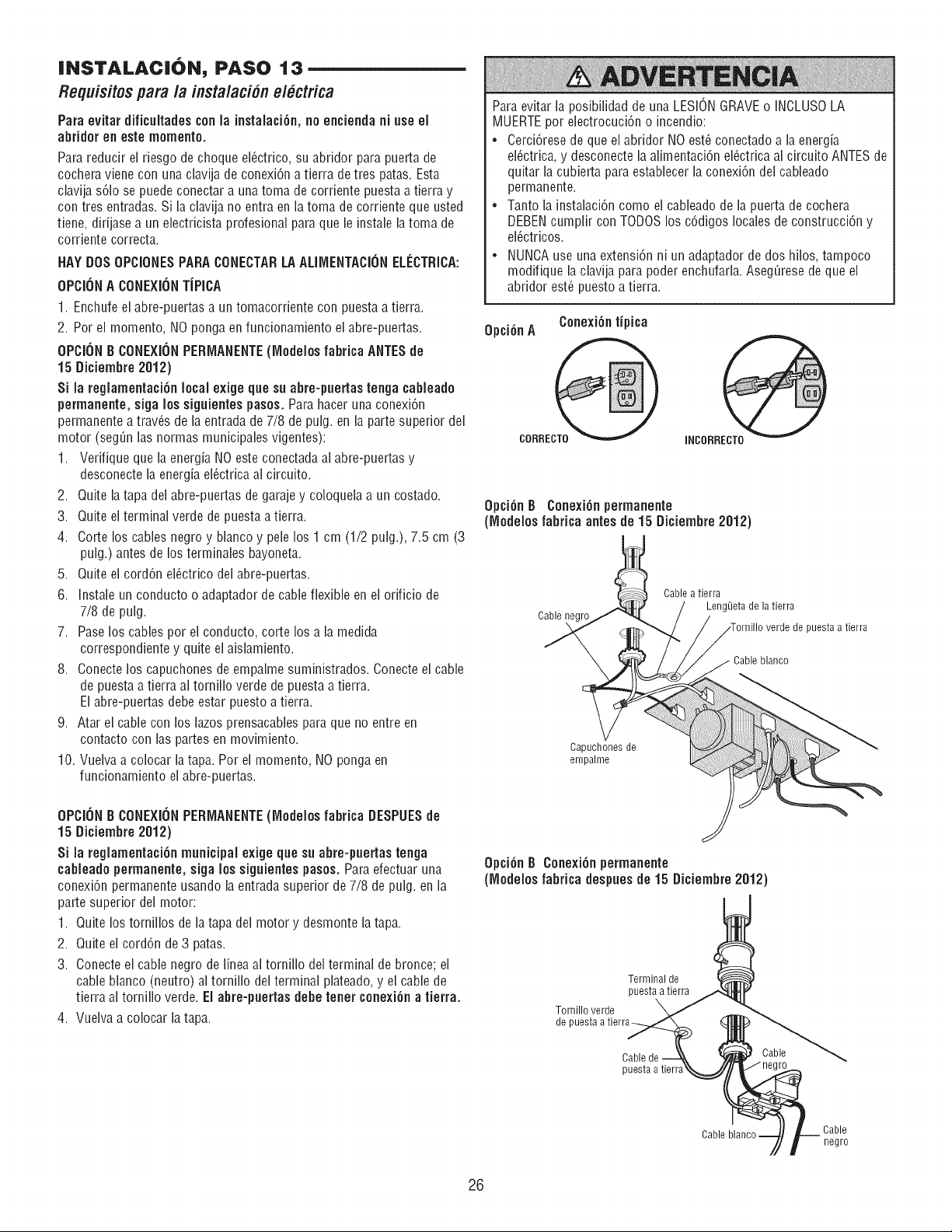
INSTALACI6N, PASO 13
Requisitespara la instalaci6nelbctrica
Para evitar dificultades conla instalaci6n, no encienda ni use el
abfidor en este memento.
Para reducir el riesgo de cheque el_ctrico, su abridor para puerta de
cochera viene con una clavija de conexi6n a tierra de tres patas. Esta
clavija s61ose puede conectar a una toma de corriente puesta a tierra y
con tres entradas. Si la clavija no entra en la toma de corriente que usted
tiene, difijase a un electricista profesional para que le instale latoma de
corriente correcta.
HAY DOS0PCIONES PARACONECTARLAALllVlENTACI6NELECTRICA:
OPCI6N A CONEXI6NTiPICA
1. Enchufe el abre-puertas a un tomacorriente con puesta a tierra.
2. Per el memento, NO ponga en funcionamiento el abre-puertas.
OPCll)N B CONEXIONPERIVlANENTE(IVledeles fabrica ANTESde
15 Diciembre 2012)
Si la regiamentaci6n local exige que su abre-puertas tenga cabieade
permanente, siga los siguientespasoso Para hacer una conexi6n
permanente a trav_s de la entrada de 7/8 de pulg. en la parte superior del
motor (seg_n las normas municipales vigentes):
1. Verifique que la energia NO este conectadaal abre-puertas y
desconecte la energia el_ctrica al circuito.
2. Quite la tapa dei abre-puertas de garaje y coloquela a un costado.
3. Quite el terminal verde de puesta a tierra.
4. Corte loscables negro y blanco y pelelos 1 cm (1/2 pulg.), 7.5 cm (3
pulg.) antes de los terminales bayoneta.
5. Quite ei cord6n el_ctrico del abre-puertas.
6. Instaleun conducto o adaptador de cableflexible en ei orificio de
7/8 de pulg.
7. Pase loscables per ei conducto, corte losa la medida
correspondiente y quite el aislamiento.
8. Conecte los capuchones de empalme suministrados. Conecte el cable
de puestaa tierra al tornillo verde de puestaa tierra.
Elabre-puertas debe estar puesto a tierra.
9. Atar el cable con los lazesprensacables para que no entre en
contacto con las partes en movimiento.
10. Vueiva a colocar latapa. Per el memento, NO ponga en
funcionamiento ei abre-puertas.
OPCI6N B CONEXI6N PERIVlANENTE(IVledelos fabrica DESPUESde
15 Diciembre 2012)
Si la regiamentaci6n municipal exige que su abre-puertas tenga
cableado permanente, siga los siguientespasos, Para efectuar una
conexi6n permanente usando la entrada superior de 7/8 de puig. en la
parte superior del motor:
1. Quite los tornillos de latapa del motor y desmonte latapa.
2. Quite ei cord6n de 3 patas.
3. Conecte el cable negro de linea al tornillo dei terminal de bronce; ei
cable bianco (neutro) al tornillo del terminal piateado, y el cablede
tierra al tornillo verde. EJabre-puertas debe tenet cenexi6na tierra,
4. Vueiva a colocar la tapa.
Para evitar la posibilidad de una LESIONGRAVEo INCLUSOLA
MUERTEper electrocuci6n o incendio:
• Cerci6rese de que el abridor NO est_ conectado a la energia
el_ctrica, y desconecte la alimentaci6n el_ctrica al circuito ANTES de
quitar la cubierta para establecer la conexi6n del cableado
permanente.
• Tanto ia instalaci6n come el cableadode la puerta de cochera
DEBENcumplir con TODOSlos c6digos locales de construcci6n y
el_ctricos.
• NUNCAuse una extensi6n ni un adaptador de dos hilos, tampoco
modifique la clavija para poder enchufafla. Aseg_rese de que el
abfidor est_ puesto a tierra.
0pci6nA
CORRECT0
Cenexi6n tipica
INCORRECTO
Opci6n B Cenexi6n permanente
(IVlodeJesfabfica antes de 15 Diciembre 2012)
Cable negro
Cable a tierra
Leng_]etade la tierra
puesta a tierra
Capuchones de
empalme
Opci6n B Conexi6n permanente
(IVledeJesfabfica despues de 15 Diciembre 2012)
Terminal de
puesta a tierra
Tornillo verde
de puesta a tierra
Cable
puesta a tierr8
Cable
Cable blanco Cable
negro
26
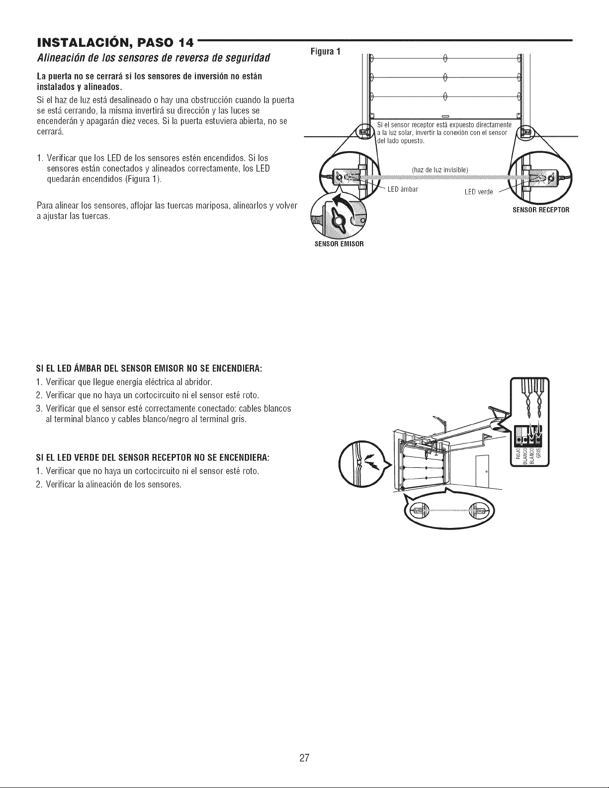
INSTALACiON, PASO 14
Alineaci6ndelossensoresde reversadeseguridad
La puerta no se cerrar_ si los sensores de inversi6n no est_n
instaladesy alineades.
Si el haz de luz est,, desalineado o hay una obstrucci6n cuando la puerta
se est&cerrando, la misma invertir_,su direcci6n y lasluces se
encender_,ny apagar_,ndiez veces. Si la puerta estuviera abierta, no se
cerrar_,.
1. Verificar que los LEDde los sensores est_n encendidos. Si los
sensores est_,nconectados y alineados correctamente, los LED
quedar_,nencendidos (Figura 1).
Para alinear los sensores, aflojar las tuercas mariposa, alinearlos y volver
a ajustar las tuercas.
Figura1
(
Si el sensor receptor est,. expuesto directamente
a la luz solar, invertir la conexiOn con el sensor
el lado opuesto.
de luz invisibll)
LED_mbar LED verde
SENSORRECEPTOR
SENSOREMISOR
SI EL LEDAMBAR DELSENSOREiVlISORNO SE ENCENDIERA:
1. Verificar que Ilegue energia el_ctrica al abridor.
2. Verificar que no haya un cortocircuito ni el sensor est_ roto.
3. Verificar que el sensor est_ correctamente conectado: cables blancos
al terminal blanco y cables blanco/negro al terminal gris.
Si EL LEDVERDEDEL SENSORRECEPTORNOSE ENCENDiERA:
1. Verificar que no haya un cortocircuito ni el sensor est_ roto.
2. Verificar la alineaci6n de los sensores.
27
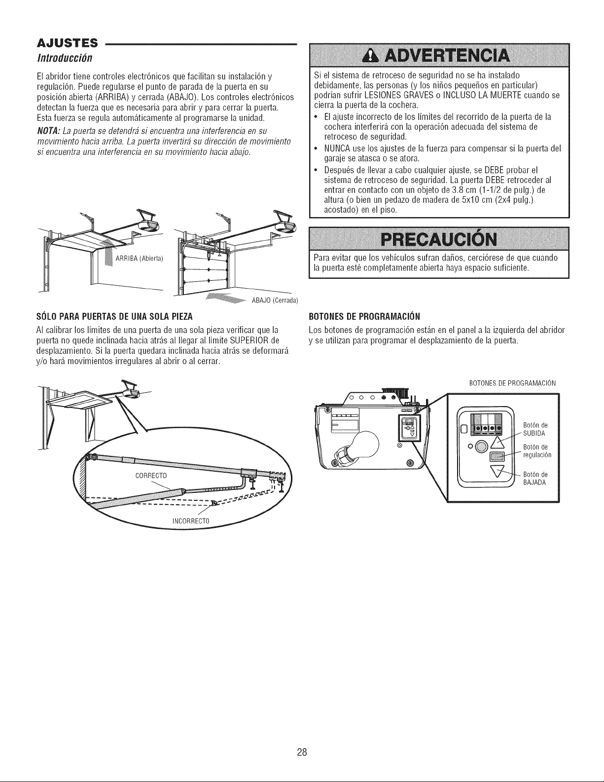
El abridor tiene controles electr6nicos que facilitan su instalaci6n y
reguhci6n. Puede reguhrse el punto de parada de la puerta en su
posici6n abierta (ARRIBA) y cerrada (ABAJO). Los controles electr6nicos
detectan la fuerza que es necesaria para abrir y para cerrar la puerta.
Esta fuerza se regula autom6,ticamenteal programarse la unidad.
NOT/I: La puerta se detendr_ si encuentra una interferencia en su
movimiento hacia arriba. La puerta inverfirb su direcci6n de movimiento
si encuentra una interferencia en su movimiento hacia abajo.
Si el sistema de retroceso de seguridad no se ha instalado
debidamente, las personas (y los ni_os peque_osen particular)
poddan sufrir LESIONESGRAVESo INCLUSOLA MUERTEcuando se
cierra la puerta de la cochera.
• Elajuste incorrecto de los limites del recorrido de la puerta de la
cochera interferir6, con la operaci6n adecuadadel sistema de
retroceso de seguridad.
• NUNCAuse los ajustes de la fuerza para compensar si la puerta del
garaje se atasca o se atora.
• Despu_sde Ibvar a cabo cualquier ajuste, se DEBEprobar el
sistema de retroceso de seguridad. La puerta DEBEretroceder al
entrar en contacto con un objeto de 3.8 cm (1-1/2 de pulg.) de
altura (o bien un pedazode madera de 5x10 cm (2x4 pulg.)
acostado) en el piso.
ARRIBA (Abierta) Para evitar que los vehiculos sufran da_os, cerci6rese de que cuando
la puerta est_ compbtamente abierta haya espacio suficiente.
ABAJO (Cerrada)
SOLOPARAPUERTASDE UNASOLAPIEZA
AI calibrar los fimites de una puerta de una sob piezaverificar que la
puerta no quede inclinada hacia atr6,sal Ilegar al limite SUPERIORde
desphzamiento. Si la puerta quedara inclinada hacia atr6,sse deformar6,
y/o bar6,movimientos irregulares al abrir o al cerrar.
CORRECTO
INCORRECTO
BOTONESDE PROGRAiVlACION
Los botones de programaci6n est6,nen el panel a la izquierda del abridor
y se utilizan para programar el desplazamiento de la puerta.
BOTONESDE PROGRAMACION
@
Bot6n de
/ SUBIDA
BotOnde
regulaciOn
_Bot6n de
BAJADA
28
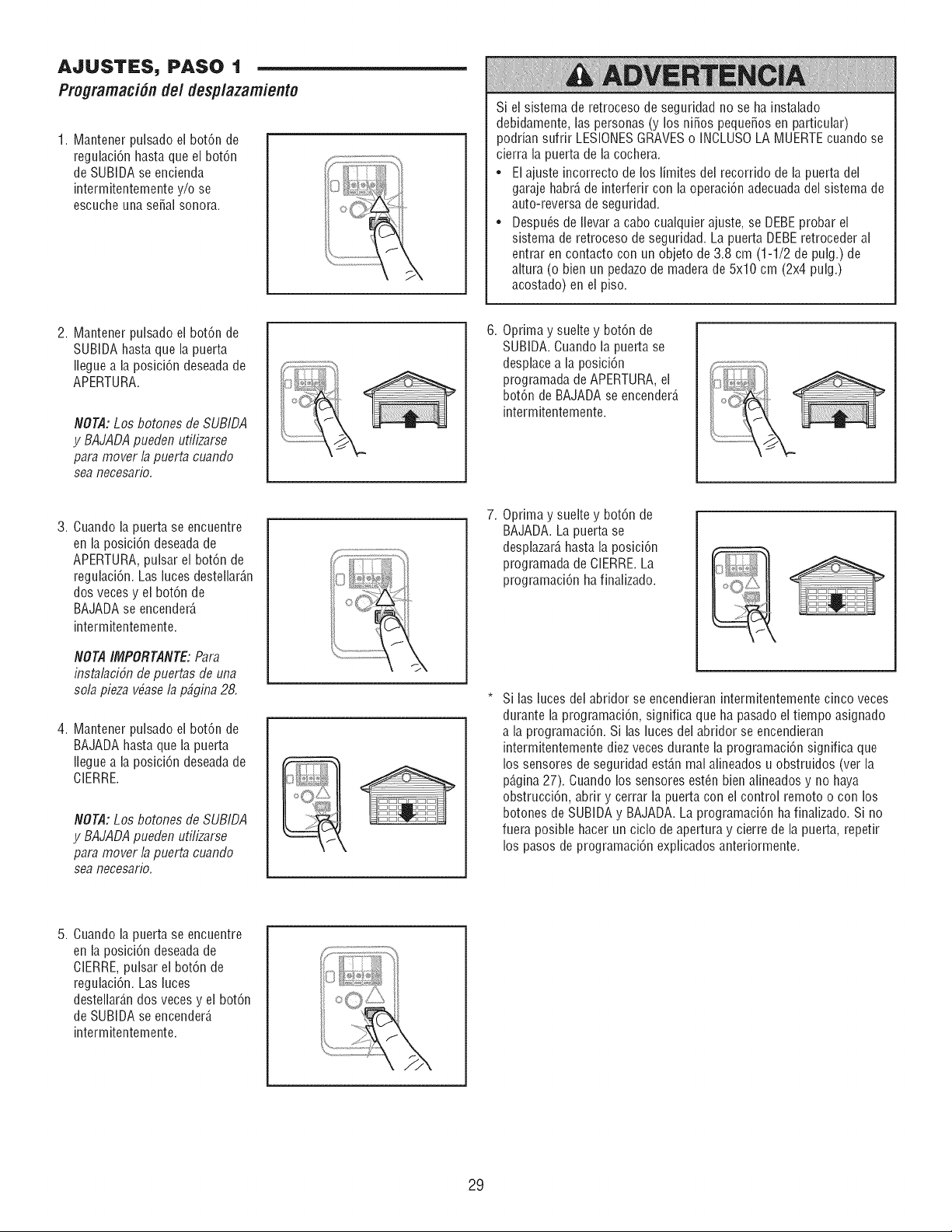
AJUSTES, PASO 1
Progmmaci6nde/desp/azamiento
1. Mantener pulsado el bot6n de
regulaci6n hasta que el bot6n
de SUBIDA se encienda
intermitentemente y/o se
escuche una sepal sonora.
2. Mantener pulsado el bot6n de
SUBIDA hasta que la puerta
Ilegue a la posici6n deseadade
APERTURA.
NOTA:Los botones de SUBIDA
y BAJADApueden utilizarse
para mover la puerta cuando
sea necesario.
3. Cuando la puerta se encuentre
en la posici6n deseadade
APERTURA,pulsar el bot6n de
regulaci6n. Las luces destellar6,n
dos veces y el bot6n de
BAJADAse encender6,
intermitentemente.
NOTAIMPORTANTE:Para
insta/aci6n de puertas de una
so/a pieza vbase/3 p_gina 28.
4. Mantener pulsado el bot6n de
BAJADAhasta que la puerta
Ilegue a la posici6n deseadade
ClERRE.
NOTA: Los botones de SUBIDA
y BAJADApueden uti/izarse
para mover/a puerta cuando
sea necesario.
5. Cuando la puerta se encuentre
en la posici6n deseadade
ClERRE,pulsar el bot6n de
regulaci6n. Las luces
destellar6,ndos veces y el bot6n
de SUBIDA se encender6,
intermitentemente.
Si el sistema de retroceso de seguridad no se ha instahdo
debidamente, las personas (y los ni_os peque_os en particular)
poddan sufrir LESIONESGRAVESo INCLUSOLA MUERTEcuando se
cierra la puerta de la cochera.
• El ajuste incorrecto de los limites del recorrido de la puerta del
garaje habr6,de interferir con la operaci6n adecuada del sistema de
auto-reversa de seguridad.
• Despu_s de Ilevar a cabo cualquier ajuste, se DEBEprobar el
sistema de retroceso de seguridad. La puerta DEBEretroceder al
entrar en contacto con un objeto de 3.8 cm (1-1/2 de pulg.) de
altura (o bien un pedazode madera de 5x10 cm (2x4 pulg.)
acostado) en el piso.
6. Oprima y suelte y bot6n de
SUBIDA. Cuando la puerta se
desphce a la posici6n
programada de APERTURA,el
bot6n de BAJADA se encender6,
intermitentemente.
7. Oprima y suelte y bot6n de
BAJADA. La puerta se
desplazar6,hasta la posici6n
programada de CIERRE.La
programaci6n ha finalizado.
Si las luces del abridor se encendieran intermitentemente cinco veces
durante la programaci6n, significa que ha pasado el tiempo asignado
a la programaci6n. Si las luces del abridor se encendieran
intermitentemente diez veces durante la programaci6n significa que
los sensores de seguridad est6,nmal afineados u obstruidos (ver la
p6,gina27). Cuando los sensores est_n bien alineados y no haya
obstrucci6n, abrir y cerrar la puerta con el control remoto o con los
botones de SUBIDA y BAJADA.La programaci6n ha finafizado. Si no
fuera posible hacer un ciclo de apertura y cierre de la puerta, repetir
los pasos de programaci6n explicados anteriormente.
29
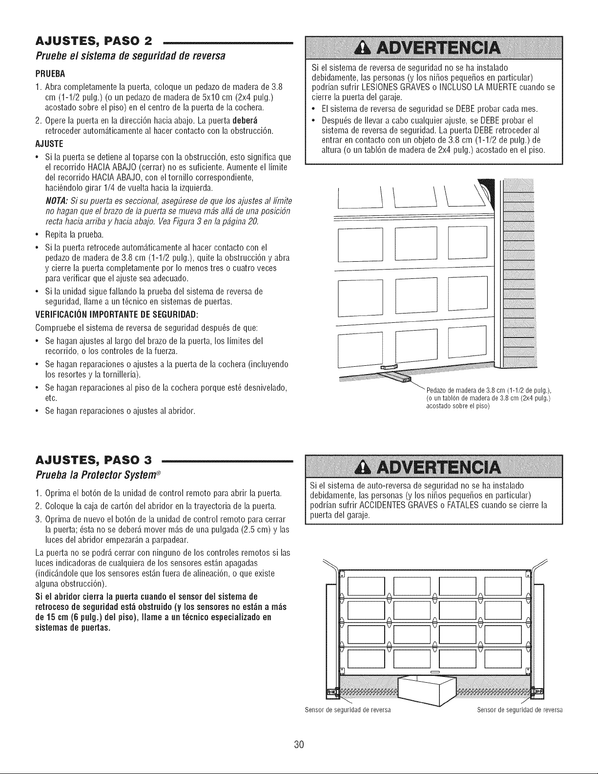
AJUSTES, PASO 2
Pruebee/sistema de seguridad de reversa
PRUEBA
1. Abra completamente la puerta, coloque un pedazode madera de 3.8
cm (1-1/2 pulg.) (o un pedazode madera de 5x10 cm (2x4 pulg.)
acostado sobre el piso) en el centro de la puerta de la cochera.
2. Opere la puerta en la direcci6n hacia abajo. La puerta deber_
retroceder autom6,ticamenteal hacer contacto con la obstrucci6n.
AJUSTE
• Si la puerta se detiene al toparse con la obstrucci6n, esto significa que
el recorrido HAClAABAJO (cerrar) no es suficiente. Aumente el limite
del recorrido HACIAABAJO,con el tornillo correspondiente,
haci_ndolo girar 1/4 de vuelta hacia la izquierda.
NOTA: Si su puerta es seccienal, asegLiresede que los ajustes al IfmM
no hagan que el braze de la puerta se mueva m#s all# de unapesici6n
recta hacia arriba y hacia abaje. VeaFigura 3 en la p#gina 20.
• Repita la prueba.
• Si la puerta retrocede autom_ticamente al hacer contacto con el
pedazode madera de 3.8 cm (1-1/2 pulg.), quite la obstrucci6n y abra
y cierre la puerta completamente por Io menos tres o cuatro veces
para verificar que el ajuste sea adecuado.
• Si la unidad sigue fallando la prueba del sistema de reversa de
seguridad, Ilame a un t_cnico en sistemas de puertas.
VERIFICACIONllVlPORTANTEDESEGURIDAD:
Compruebe el sistema de reversa de seguridad despu_s de que:
• Se haganajustes al largo del brazo de la puerta, los limites del
recorrido, o los controles de la fuerza.
• Se hagan reparacioneso ajustes a la puerta de la cochera (incluyendo
los resortes y la tornilleria).
• Se hagan reparacionesal piso de la cochera porque est_ desnivelado,
etc.
• Se hagan reparacioneso ajustes al abridor.
Si el sistema de reversa de seguridad no se ha instalado
debidamente, las personas (y los ni_os peque_os en particular)
podrian sufrir LESIONESGRAVESo INCLUSOLA MUERTEcuando se
cierre la puerta del garaje.
• El sistema de reversa de seguridad se DEBEprobar cada mes.
• Despu_s de Ilevar a cabo cualquier ajuste, se DEBEprobar el
sistema de reversa de seguridad. La puerta DEBEretroceder al
entrar en contacto con un objeto de 3.8 cm (1-1/2 de pulg.) de
altura (o un tabl6n de madera de 2x4 pulg.) acostado en el piso.
]
(o un tablOn de madera de 3.8 cm (2x4 pulg.)
acostado sobre el piso)
AJUSTES, PASO 3
Pruebala ProtectorSystem®
1. Oprima el bot6n de la unidad de control remoto para abrir la puerta.
2. Coloque la caja de cart6n del abridor en latrayectoria de la puerta.
3. Oprima de nuevo el bot6n de la unidad de control remoto para cerrar
la puerta; _sta no se deber_ mover m_s de una pulgada (2.5 cm) y las
luces del abridor empezar_n a parpadear.
La puerta no se podr_ cerrar con ninguno de los controles remotos si las
luces indicadoras de cualquiera de los sensores est6.napagadas
(indic6,ndoleque los sensores estAnfuera de alineaci6n, o que existe
alguna obstrucci6n).
Si el abridor cierra la puerta cuandoel sensor del sistema de
retrocesode seguridad est_ obstruido(y los sensoresno est_n a m_s
de 15 cm (6 pulgo)del piso), Ilame a un t_cnico especializado en
sistemas de puertas.
Si el sistema de auto-reversa de seguridad no se ha instalado
debidamente, las personas (y los ni_os peque_os en particular)
podrian sufrir ACCIDENTESGRAVESo FATALEScuando se cierre la
puerta del garaje.
Sensor de seguridad de reversa Sensor de seguridad de reversa
30
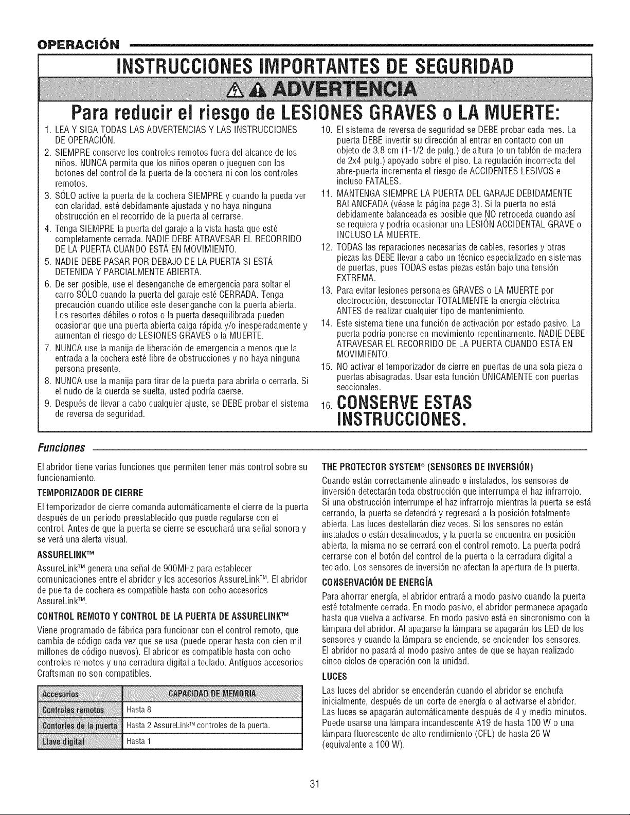
OPERACJ6N
INSTRUCCiONESllViPORTANTESDESEGURIDAD
Para reducirel
riesgode LESIONESGRAVESo LA IVIUERTE:
1. LEAY SIGA TODAS LAS ADVERTENCIASY LAS INSTRUCCIONES 10. El sistema de reversa de seguridad se DEBEprobar cada mes. La
DEOPERACION. puerta DEBEinvertir su direcciCn al entrar en contacto con un
2. SIEMPRE conserve los controles remotos fuera del alcance de los
ni_os. NUNCApermita que los ni_os operen o jueguen con los
botones del control de la puerta de la cochera ni con los controles
remotos.
3. SOLOactive la puerta de la cochera SIEMPREy cuando la pueda ver
con ciaridad, est_ debidamente ajustada y no haya ninguna
obstrucciCn en ei recorrido de la puerta al cerrarse.
4. Tenga SiEMPRE la puerta del garaje a ia vista hasta que est_
completamente cerrada. NADIEDEBEATRAVESAREL RECORRIDO
DELA PUERTACUANDOEST', EN MOVIMIENTO.
5. NADIEDEBEPASARPORDEBAJODE LA PUERTASI EST',
DETENIDAY PARCIALMENTEABIERTA.
6. Deset posible, use el desenganche de emergencia para soltar el
carro SOLOcuando la puerta del garaje est_ CERRADA.Tenga
precauciCncuando utilice estedesenganche con la puerta abierta.
Los resortes d_biies o rotos o la puerta desequilibrada pueden
ocasionar que una puerta abierta caiga rC,pida y/o inesperadamentey
aumentan el riesgo de LESIONESGRAVESo la MUERTE.
7. NUNCAuse la manila de liberaciCn de emergencia a menos que la
entrada a la cochera est_ fibre de obstrucciones y no haya ninguna
persona presente.
8. NUNCAuse la manila para tirar de la puerta para abrirla o cerrarla. Si
ei nudo de la cuerda se sueita, usted podria caerse.
9. Despu_sde Ilevar a cabo cualquier ajuste, se DEBEprobar el sistema
de reversa de seguridad.
objeto de 3.8 cm (1-1/2 de pulg.) de altura (o un tablCn de madera
de 2x4 pulg.) apoyado sobre el piso. La regulaciCnincorrecta del
abre-puerta incrementa el riesgo de ACCIDENTESLESIVOSe
incluso FATALES.
11. MANTENGASIEMPRELA PUERTADEL GARAJEDEBIDAMENTE
BALANCEADA(vCasela pC,gina page 3). Si la puerta no est,.
debidamente balanceadaes posible que NO retroceda cuando asi
se requiera y podda ocasionar una LESIONACCIDENTALGRAVEo
INCLUSOLA MUERTE.
12. TODASlas reparacionesnecesarias de cables, resortes y otras
piezas las DEBEIlevar a cabo un t_cnico especializadoen sistemas
de puertas, pues TODASestas piezasestC,n bajo una tensiCn
EXTREMA.
13. Para evitar lesiones personales GRAVESo LA MUERTEpot
electrocuciCn, desconectar TOTALMENTEla energia el_ctrica
ANTES de realizar cualquier tipo de mantenimiento.
14. Estesistema tiene una funciCn de activaciCn pot estado pasivo. La
puerta podria ponerse en movimiento repentinamente. NADIE DEBE
ATRAVESAREL RECORRIDODE LA PUERTACUANDOEST', EN
MOVIMIENTO.
15. NOactivar ei temporizador de cierre en ,puertasde una sola pieza o
puertas abisagradas. Usar estafunciCn UNICAMENTEcon puertas
seccionales.
16.CONSERVEESTAS
INSTRUCCiONES.
Funciones
El abridor tiene varias funciones que permiten tener mC,s control sobre su
funcionamiento.
TEiViPORIZADORDE CIERRE
Eltemporizador de cierre comanda automC,ticamente el cierre de la puerta
despuCsde un periodo preestabiecido que puede regularse con ei
control. Antes de que la puerta se cierre se escucharC,una sepal sonora y
se verC,una alerta visual.
ASSURELINKTM
AssureLinkTM genera una sepal de 900MHz para establecer
comunicaciones entre el abridor y los accesorios AssureLinkTM. El abridor
de puerta de cochera es compatible hasta con ocho accesorios
AssureLinkTM.
CONTROLREiVlOTOY CONTROLDELA PUERTADEASSURELiNKTM
Viene programado de fC,brica para funcionar con el control remoto, que
cambia de cCdigo cadavez que se usa (puede operar hasta con cien mil
millones de cCdigo nuevos). El abridor es compatible hasta con ocho
controles remotos y una cerradura digital a teclado. Antiguos accesorios
Craftsman no son compatibles.
Hasta 8
Hasta2 AssureLinkTMcontrolesde lapuerta.
Hasta1
THE PROTECTORSYSTEiVP(SENSORESDE INVERSI(}N)
Cuando estC,n correctamente alineado e instalados, los sensores de
inversiCn detectarC,n toda obstrucciCn que interrumpa el haz infrarrojo.
Si una obstrucciCn interrumpe el haz infrarrojo mientras la puerta se estC,
cerrando, ia puerta se detendrC,y regresarC,a ia posiciCn totalmente
abierta. Las iuces destellarC,n diez veces. Si los sensores no est_.n
instalados o estC,n desalineados,y la puerta se encuentra en posiciCn
abierta, la misma no se cerrarC,con ei control remoto. La puerta podrC,
cerrarse con el botCn del control de la puerta o la cerradura digital a
teclado. Los sensores de inversiCn no afectan laapertura de la puerta.
CONSERVACI(}NDEENERGiA
Para ahorrar energia, el abridor entrarC,a modo pasivo cuando la puerta
est_totalmente cerrada. En modo pasivo, el abridor permanece apagado
hasta que vuelva a activarse. En modo pasivo estC,en sincronismo con la
16,mparadel abridor. AI apagarse la 16,mparase apagarC,n los LED de los
sensores y cuando la 16,mparase enciende, se encienden los sensores.
El abridor no pasarC,al modo pasivo antes de que se hayan realizado
cinco ciclos de operaciCn con la unidad.
LUCES
Las luces del abridor se encenderC,n cuando el abridor se enchufa
inicialmente, despu_s de un corte de energia o al activarse el abridor.
Las luces se apagarC,n automC,ticamente despu_s de 4 y medic minutos.
Puedeusarse una 16,mparaincandescenteA19 de hasta 100 W ouna
16,mparafluorescente de alto rendimiento (CFL) de hasta 26 W
(equivalente a 100 W).
31
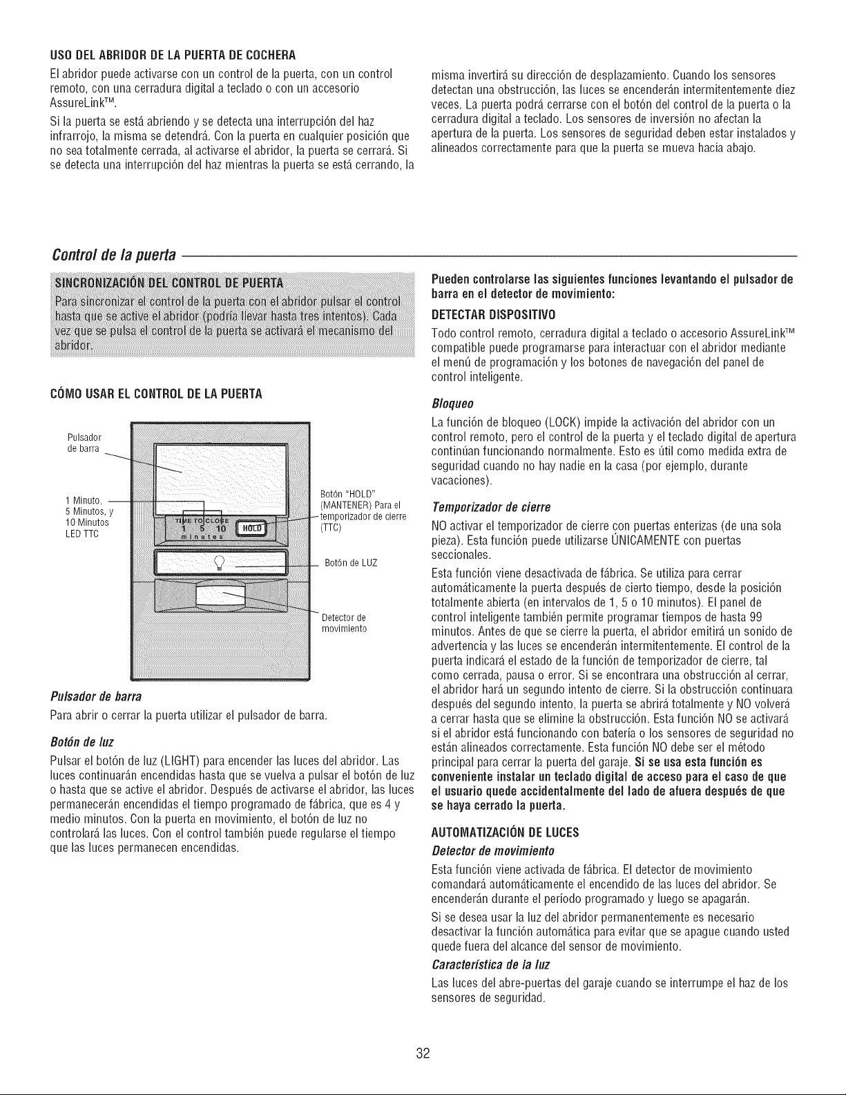
USO DELABRiDORDELA PUERTADE COCNERA
El abridor puede activarse con un control de la puerta, con un control
remote, con una cerradura digital a teclado o con un accesorio
AssureLinkTM.
Si la puerta se est6,abriendo y se detecta una interrupci6n del haz
infrarrojo, la misma se detendr6,.Con la puerta en cualquier posici6n que
no seatotalmente cerrada, al activarse el abridor, la puerta se cerrar6,.Si
se detecta una interrupci6n del haz mientras la puerta se est6,cerrando, la
misma invertir6,su direcci6n de desplazamiento.Cuando los sensores
detectan una obstrucci6n, las luces se encender6,nintermitentemente diez
veces. La puerta podr6,cerrarse con el bot6n del control de la puerta o la
cerradura digital a teclado. Los sensores de inversi6n no afectan la
apertura de la puerta. Los sensores de seguridad deben estar instalados y
alineados correctamente paraque la puerta se mueva haciaabajo.
Control de la puerta
COMOUSARELCONTROLDELAPUERTA
Pulsador
de barra
Bot6n "HOLD"
1 Minute, -- (MANTENER) Para el
5 Minutes, y )orizador de cierre
10 Minutes
LED TTC (TTC)
BotOn de LUZ
Detector de
movimiento
Pulsadorde barra
Paraabriro cerrarla puertautilizarel pulsadordebarra.
8otfin de luz
Pulsar el bot6n de luz (LIGHT) para encender las luces del abridor. Las
luces continuar6,n encendidas hasta que se vuelva a pulsar el bot6n de luz
o hasta que se active el abridor. Despu6s de activarse el abridor, las luces
permanecer6,nencendidas eltiempo programado def6,brica,que es 4 y
medio minutes. Con la puerta en movimiento, el bot6n de luz no
controlar6, las luces. Con el control tambi_n puede regularse el tiempo
que las luces permanecen encendidas.
Puedencontrolarselas siguientesfuncioneslevantandoel pulsadorde
batraenel detectorde movimiento:
DETECTARDISPOSmVO
TodDcontrol remote, cerradura digital a teclado o accesorio AssureLinkTM
compatible puede programarse para interactuar con el abridor mediante
el men_ de programaci6n y los botones de navegaci6n del panel de
control inteligente.
B/oqueo
La funci6n de bloqueo (LOCK) impide la activaci6n del abridor con un
control remote, pero el control de la puerta y el teclado digital de apertura
contin_an funcionando normalmente. Esto es Qtil come medida extra de
seguridad cuando no hay nadie en la casa (per ejemplo, durante
vacaciones).
Temporizador de cierre
NO activar el temporizador de cierre con puertas entefizas (de una sola
pieza). Estafunci6n puede utifizarse 0NICAMENTEcon puertas
seccionales.
Esta funci6n viene desactivada de f6,brica.Se utifiza para cerrar
autom6,ticamentela puerta despu_s de cierto tiempo, desde la posici6n
totalmente abierta (en intervalos de 1, 5 o 10 minutes). El panel de
control inteligentetambi_n permite programar tiempos de hasta 99
minutes. Antes de que se cierre la puerta, el abfidor emitir6,un sonido de
advertencia y las luces se encender6,nintermitentemente. El control de la
puerta indicar6,el estado de la funci6n de tempofizador de cierre, tal
come cerrada, pausa o error. Si se encontrara una obstrucci6n al cerrar,
el abridor har6,un segundo intento de cierre. Si la obstrucci6n continuara
despu_s del segundo intento, la puerta se abrir6,totalmente y NOvolver6,
a cerrar hasta que se elimine la obstrucci6n. Estafunci6n NOse activar6,
si el abridor est6,funcionando con bateda o los sensores de seguridad no
est6,nalineados correctamente. Esta funci6n NOdebe ser el m_todo
principal para cerrar la puerta del garaje. Si se usa esta funci6n es
convenienteinstalat un teclado digital de acceso para el caso de que
el usuarioquede accidentalmente del lade de afuera despu_s de que
se haya cerrado la puerta.
AUTOIVIATIZACIONDE LUCES
Detector de movimiento
Esta funci6n viene activada de f6,brica. El detector de movimiento
comandar6,autom_.ticamenteei encendido de las luces dei abridor. Se
encender6,ndurante el periodo programado y luego se apagar6,n.
Si se desea usar la luz dei abridor permanentemente es necesario
desactivar la funci6n autom6,ticapara evitar que se apague cuando usted
quede fuera del alcance dei sensor de movimiento.
Caracteristica de la luz
Las luces del abre-puertas del garaje cuando se interrumpeel haz de los
sensores de seguridad.
32
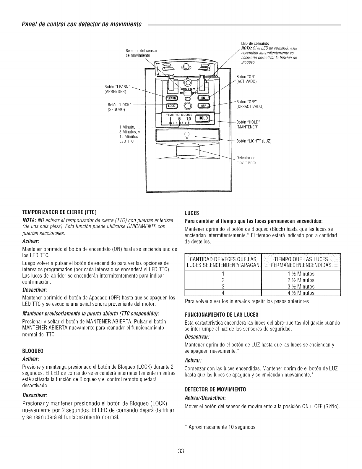
Pane/de control con detectorde movimiento
Selector del sensor
de movimiento
Bot6n "LEARN"_ -!
(APRENDER)
Bot6n "LOCK"
(SEGURO)
1 Minuto, --
LED de comando
. NOTA:Si el LED de comando estd
_ Bloqueo.
_[[Z[L ._ _ I Bot6n''ON''
_ J(ACTIVADO)
_ IBot6n "OFF"
_ iDESACTIVADO)
5 Minutos, y
10 Minutos
LED TTC
-- Bot6n "LIGHT" (LUZ)
__ Detector de
movimiento
TEMPORIZADORDECIERRE(TTC)
NOT,d: NO activar el temporizador de cierre (TTC) con puertas enterizas
(de una sola pieza). Esta funci6n puede ufilizarse UNICAMENTEcon
puertas seccionales.
Activar:
Mantener oprimido el bot6n de encendido (ON) hasta se encienda uno de
los LEDTTC.
Luego volver a pulsar ei bot6n de encendido para ver las opciones de
intervalos programados (pot cada intervalo se encender_,ei LED TTC).
Las luces del abridor se encender_,nintermitentemente para indicar
confirmaci6n.
Besactivar:
Mantener oprimido el bot6n de Apagado (OFF)hasta que se apaguen los
LEDTTC y se escuche una sepal sonora proveniente del motor.
Mantenerprovisofiamentela puertaaflierta (TTCsuspendido):
Presionary soltar el bot6nde MANTENERABIERTA.Pulsarel bot6n
MANTENERABIERTAnuevamenteparareanudarelfuncionamiento
normaldel TTC.
BLOQUEO
Activar:
Presione y mantenga presionado el bot6n de Bloqueo (LOCK)durante 2
segundos. El LED de comando se encender_,intermitentemente mientras
est_ activada la funci6n de Bloqueo y el control remoto quedar_,
desactivado.
Desactivar:
Presionar y mantener presionado el bot6n de Bloqueo (LOCK)
nuevamentepor 2 segundos, El LEDde comando dejard de titilar
y se reanudardel funcionamiento normal.
LUCES
Para cambiar el tiempo que ias iuces permanecen encendidas:
Mantener oprimido el bot6n de BIoqueo (Block) hasta que las luces se
enciendan intermitentemente.*El tiempo estar_,indicadopor la cantidad
de destellos.
CANTIDADDE VECESQUELAS TIEMPO QUELAS LUCES
LUCESSEENCIENDENY APAGAN
1
2
3
4
PERMANECENENCENDIDAS
1 ½ Mlinutos
2 ½ Minutos
3 ½ Mlinutos
4 ½ Minutos
Para volver a vet los intervalos repetir los pasosanteriores.
FUNCIONAiVlIENTODE LAS LUCES
Esta caracteristica encender_,ias luces dei abre-puertas dei garaje cuando
se interrumpeel haz de los sensores de seguridad.
Desactivar:
Mantener oprimido ei bot6n de LUZ hasta que las luces se enciendan y
se apaguen nuevamente.*
AcUvar:
Comenzar con las luces encendidas. Mantener oprimido el bot6n de LUZ
hasta que las luces se apagueny se enciendan nuevamente.*
DETECTORDE IVIOVllVIIENTO
ActivaffDesacfivar:
Mover el bot6n del sensor de movimiento a la posici6n ON u OFF(SFNo).
* Aproximadamente 10 segundos
33
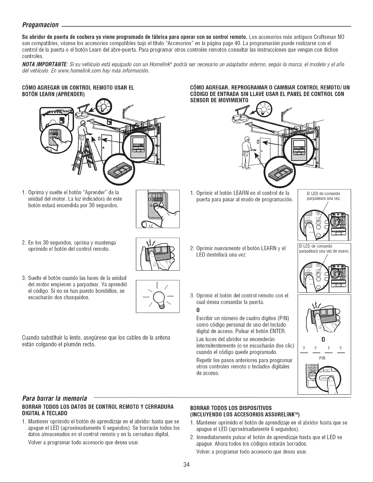
Progamacion
Su abfidor de puerta de cocheraya viene programadode f_brica para operar consu control remote. Los accesorios m_s antiguos Craftsman NO
son compatibles, v_anse los accesofios compatibles bajo el titulo "Accesorios" en la p_,ginapage40. La programaciGn puede reafizarsecon el
control de la puerta o el botGn Learn del abre-puerta. Para programar otros controles remotos consultar las instruccionesque vengan con dichos
controles.
NOTAIMPORTANTE:Si su vehfculo est_ equipado con un Homelinl(_ podrfa ser necesario un adaptador externo, segLinla mama, el modelo y el afio
del vehfculo. En www.homelink.com hay mbs informaciGn.
COMOAGREGARUN CONTROLREIVIOTOUSAREL
BOTONLEARN(APRENDER)
COIVlOAGREGAR,REPROGRAiVlAR0 CAMBIARCONTROLREiVIOTO/UN
CODIGODE ENTRADASIN LLAVEUSAR ELPANELDE CONTROLCON
SENSORDE IVlOVllVlIENTO
1. Optima y suelte el bot6n "Aprender" de la
unidad del motor. La luz indicadorade este
botGn estar_,encendida per 30 segundos.
1. Oprimir el botGn LEARNen el control de la ElLEDdecomando
puerta para pasar al mode de programaciGn, parpadear_unavez.
2. En los 30 segundos, optima y mantenga
oprimido el bot6n del control remote.
2. Oprimir nuevamente el botGn LEARNy el
LED destellar_,una vez.
El LED de comando nuevo.
parpadear_,una vez de
3. Suelte el botGn cuando las luces de la unidad
del motor empiecen a parpadear. Ya aprendi6
ei cGdigo. Si no se han puesto bombillos, se
escuchar_,ndos chasquidos.
Cuandosubstituir la lente, asegQresequelos cablesde la antena
est_,ncolgandoel plumOnrecto.
,
Oprimir el botGn del control remote con el
cual desea comandar la puerta.
O
Escribir un n_mero de cuatro digitos (PIN)
come cGdigo personal de use del teclado
digital de acceso. Pulsar el botGn ENTER.
Las luces del abridor se encender_,n
intermitentemente (o se escuchar_,ndos clic)
cuando el cGdigoquede programado.
Repetir los pasos antefiores para programar
otros controles remote o teclados digitales
de acceso.
Para better la memoria
BORRARTODOSLOS DATOSDECONTROLREIVlOTOY CERRADURA
DIGITALA TECLADO
1. Mantener oprimido el botGn de aprendizajeen el abridor hasta que se
apague el LED (aproximadamente 6 segundos). Se borrar_,ntodos los
dates almacenados en el control remote y en la cerradura digital.
Volver a programar todo accesorio que desea usar.
BORRARTODOSLOSDISPOSmVOS
(INCLUYENDOLOSACCESORIOSASSURELINKTM)
0
? ? ? ?
PIN
1. Mantener oprimido el botGn de aprendizajeen el abridor hasta que se
apague el LED (aproximadamente 6 segundos).
2. Inmediatamente pulsar el botGnde aprendizaje hasta que el LED se
apague. Ahora todos los cGdigos estar_,nborrados.
Volver a programar todo accesorio que desea usar.
34
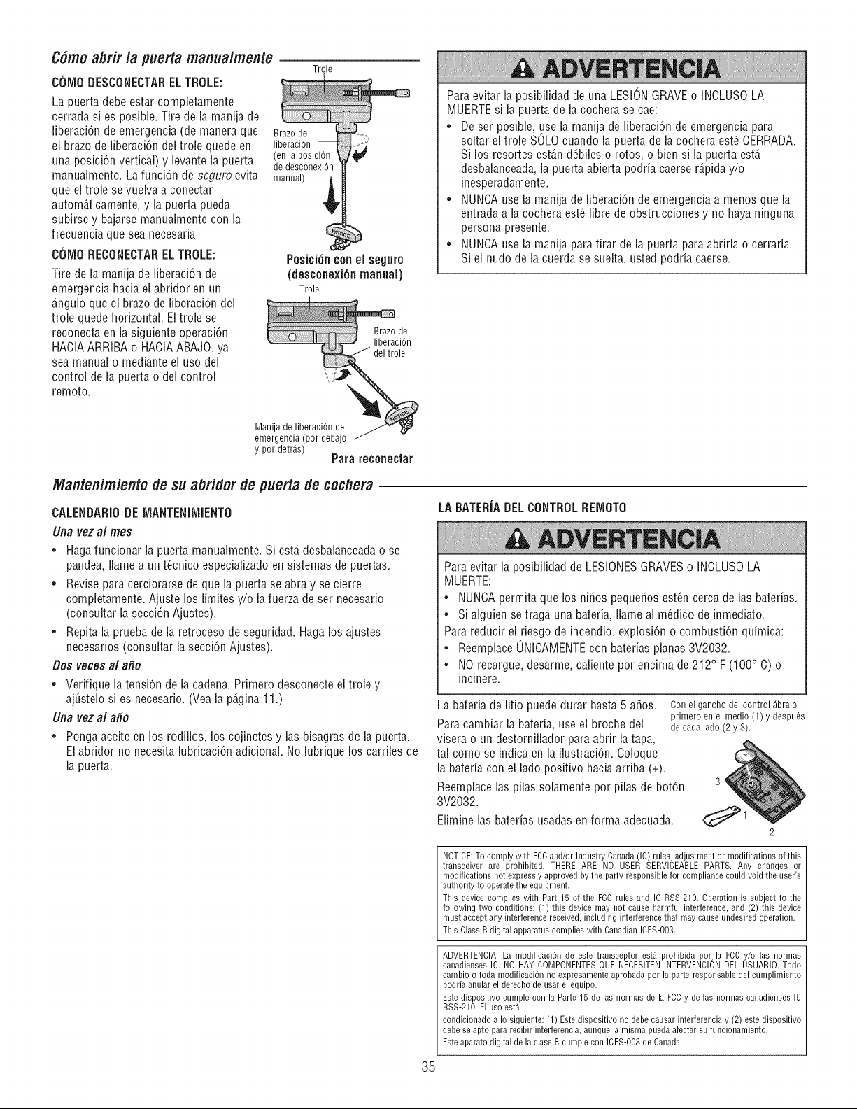
C6mo abrir la puerta manualmente
COIVIODESCONECTARELTROLE:
Trole
La puerta debe estar completamente
cerrada si es posible. Tire de la manija de
fiberaciOnde emergencia (de manera que
el brazo de fiberaciOndel trole quede en
una posiciOn vertical) y levante la puerta
manualmente. La funciOn de seguro evita
que el trole se vuelva a conectar
automO,ticamente, y la puerta pueda
subirse y bajarse manualmente con la
frecuencia que sea necesaria.
COMO RECONECTAREL TROLE:
Tire de la manija de fiberaciOnde
emergencia hacia el abridor en un
6.nguloque el brazo de fiberaciOndel
trole quede horizontal. El trole se
reconecta en la siguiente operaciOn
HACIAARRIBA o HAClA ABAJO,ya
sea manual o mediante el uso del
control de la puerta o del control
remoto.
Brazo de
liberaciOn
(en la posiciOn
de desconexiOn
manual)
Posicibncon el seguro
(desconexi6nmanual)
Trole
Brazo de
liberaci6n
del trole
Para evitar la posibilidad de una LESIONGRAVEo INCLUSOLA
MUERTEsi la puerta de la cochera se cae:
• De ser posible, use la manija de fiberaciOnde emergencia para
soltar el trole SOLO cuando la puerta de la cochera est6 CERRADA.
Si los resortes estO,n d_biles o rotos, o bien si la puerta estO,
desbalanceada,la puerta abierta podda caerse rO,pida y/o
inesperadamente.
• NUNCAuse la manija de liberaciOnde emergencia a menos que la
entrada a la cochera est_ fibre de obstrucciones y no haya ninguna
persona presente.
• NUNCAuse la manija para tirar de la puerta paraabrirla o cerrarla.
Si el nudo de la cuerda se suelta, usted podria caerse.
Manija de liberaciOn de
emergencia (por debajo
y por detrgs)
Pata teconectar
Mantenimientode su abridorde puerta de cochera
CALENDARIODE IVlANTENilVlIENTO
Llna vez al mes
• Haga funcionar la puerta manualmente. Si est6,desbalanceadao se
pandea, Ilamea un t_cnico especializado en sistemas de puertas.
• Revise para cerciorarse de que ia puerta se abra y se cierre
completamente. Ajuste los limites y/o la fuerza de ser necesario
(consultar la secci6n Ajustes).
• Repita la prueba de la retroceso de seguridad. Hagalos ajustes
necesarios (consultar la secci6n Ajustes).
Dos veces al afio
• Verifique la tension de la cadena. Primero desconecte el trole y
aj_stelo si es necesario. (Vea la pO,gina 11.)
Una vez al afio
• Ponga aceite en los rodillos, los cojinetes y las bisagras de la puerta.
El abridor no necesita lubricaciOn adicional. No lubrique los carriles de
la puerta.
LABATER[ADELCONTROLREIVIOTO
Para evitar la posibilidad de LESIONESGRAVESo INCLUSOLA
MUERTE:
• NUNCApermita que los ni_os peque_os est_n cerca de las batedas.
• Si alguien setraga una bateda, Ilameal m_dico de inmediato.
Para reducir el riesgo de incendio, explosion o combustion quimica:
• Reemplace 0NICAMENTEcon batedas planas 3V2032.
• NO recargue, desarme, caliente por encima de 212° F (100° C) o
incinere.
La bateda de litio puede durar hasta 5 a_os.
Para cambiar la bateda, use el broche del
visera o un destornillador paraabrir latapa,
tal como se indica en la ilustraci6n. Coloque
la bateda con el lado positivo haciaarriba (+).
Reemplace las pilas solamente pot pilas de bot6n
3V2032.
Elimine las batefias usadas en forma adecuada.
Con el gancho del control _.bralo
primero en el medio (1) y despu6s
de cada lado (2 y 3).
2
NOTICE:To comply with FCCand/or Industry Canada(IC) rules, adjustment or modifications of this
transceiver are prohibited. THERE ARE NO USER SERVICEABLEPARTS. Airy changes or
modifications not expressly approved by the party responsiblefor compliance could void the user's
authority to operate the equipment.
This device complies with Part 15 of the FCCrules and IC RSS-210. Operation is subject to the
following two conditions: (1) this device may not cause harmful interfereuce,and (2) this device
must accept any interferencereceived, includiug iuterferencethat may cause undesired operation.
This ClassB digital apparatuscomplies with CanadianICES-O03.
ADVERTENCIA: La modificacibn de este transceptor est5 prohibida por la FCC y/o las normas
canadieuses IC. NO HAY COMPONENTES QUE NECESITEN INTERVENCION DEL USUARIO. Todo
cambio o toda modificacibn no expresamente aprobada por la parte responsable del cumplimiento
podria anular el derecho de usar el equipo.
Este dispositivo cumple con la Parte 15 de las normas de la FCC y de las uormas canadienses IC
RSS-BIO. El uso est5
condicionado a Io siguiente: (1) Este dispositivo no debe causar interferencia y (2) este dispositivo
debe se apto para recibir iuterferencia, aunque la misma pueda afectar su funcionamiento.
Este aparato digital de la clase B cumple con ICES-O03 de Canada.
35
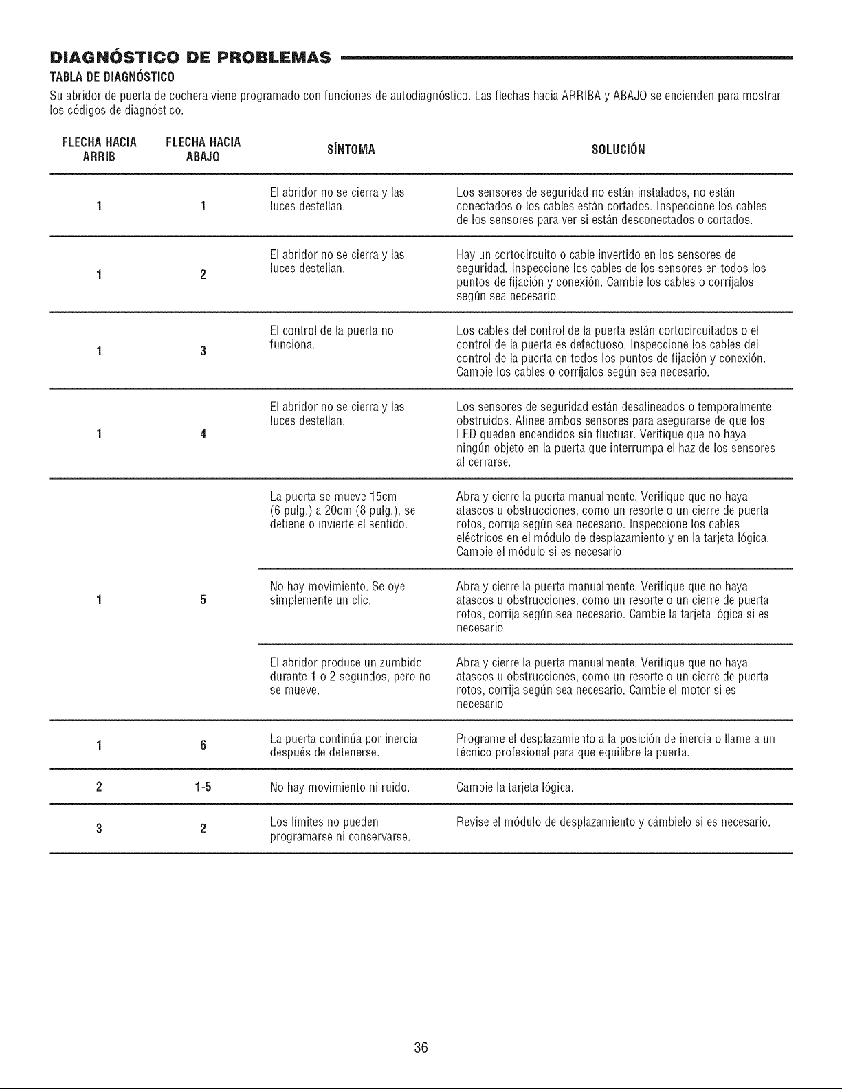
DIAGNOST|CO DE PROBLEMAS
TABLA DE DIAGN6STICO
Su abridor de puerta de cochera viene programado con funciones de autodiagn6stico. Las flechas hacia ARRIBA y ABAJO se encienden para mostrar
los c6digos de diagn6stico.
FLECHAHACIA FLECHAHACIA S[NTOIVlA SOLUCION
ARRIB ABAJO
El abridor no se cierra y las
luces destellan.
Los sensores de seguridad no est_.ninstalados, no est_.n
conectados o los cables est6,ncortados. Inspeccione los cables
de los sensores para ver si est6,ndesconectados o cortados.
El abridor no se cierra y las
luces destellan.
Hay un cortocircuito o cable invertido en los sensores de
seguridad. Inspeccioneloscables de lossensores en todos los
puntos de fijaci6n y conexi6n. Gamble los cables o cordjalos
segQnsea necesario
El control de la puerta no
funciona.
Los cables del control de la puerta est_.ncortocircuitados o el
control de la puerta es defectuoso. Inspeccione los cables dei
control de ia puerta en todos los puntos de fijaci6n y conexi6n.
Cambie los cables o corrijalos seg_n sea necesario.
El abridor no se cierra y las
luces destellan.
Los sensores de seguridad est6,ndesalineadoso temporalmente
obstruidos. Alinee ambos sensores para asegurarse de que los
LED queden encendidos sin fluctuar. Verifique que no haya
ning_n objeto en la puerta que interrumpa el haz de los sensores
al cerrarse.
La puerta se mueve 15cm
(6 pulg.) a 20cm (8 pulg.), se
detiene o invierte ei sentido.
Abra y cierre la puerta manualmente. Verifique que no haya
atascos u obstrucciones, como un resorte o un cierre de puerta
rotos, corrija seg_n sea necesario. Inspeccione los cables
el_ctricos en el m6dulo de desplazamiento yen la tarjeta 16gica.
Cambie el m6dulo si es necesario.
No hay movimiento. Se oye
simplemente un clic.
Abra y cierre la puerta manualmente. Verifique que no haya
atascos u obstrucciones, como un resorte o un cierre de puerta
rotos, corrija seg_n sea necesario.Cambie la tarjeta 16gicasi es
necesario.
El abridor produce un zumbido
durante 1 o 2 segundos, pero no
se mueve.
Abra y cierre la puerta manualmente. Verifique que no haya
atascos u obstrucciones, como un resorte o un cierre de puerta
rotos, corrija seg_n sea necesario.Cambie el motor si es
necesario.
1 6 La puerta continua por inercia Programe el desplazamiento a la posici6n de inercia o Ilame a un
despu_s de detenerse, t_cnico profesional para que equilibre la puerta.
2 1-5 No hay movimiento ni ruido. Cambie la tarjeta 16gica.
Los limites no pueden Revise el m6dulo de desplazamientoy c6,mbielosi es necesario.
3 2
programarse ni conservarse.
36
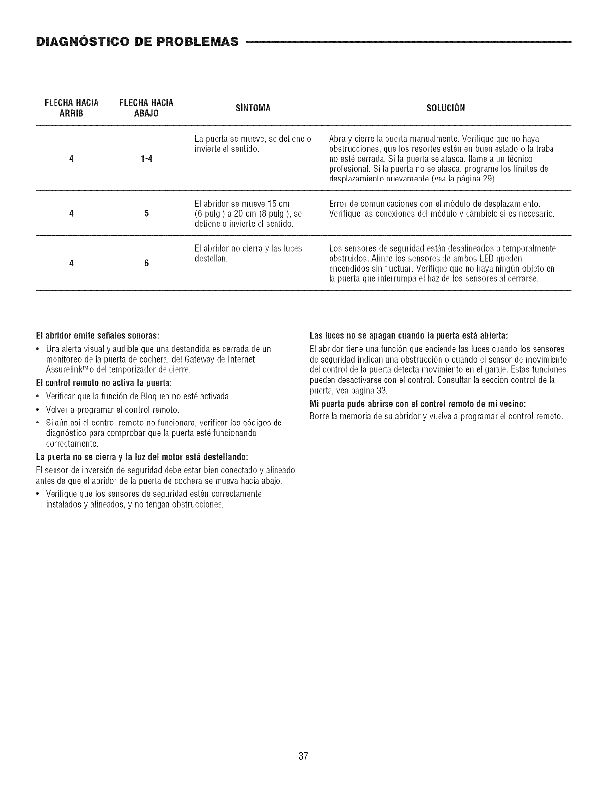
DIAGN6STICO DE PROBLEMAS
FLECHAHACIA FLECHAHACIA S[NTOMA SOLUCION
ARRIB ABAJO
1-4
La puerta se mueve, se detiene o
invierte el sentido.
Abra y cierre la puerta manualmente. Verifique que no haya
obstrucciones, que los resortes est_n en buen estado o la traba
no est_ cerrada. Si la puerta se atasca, Ilame a un t_cnico
profesional. Si la puerta no se atasca, programe los limitesde
desplazamiento nuevamente(vea la p6,gina29).
El abridor se mueve 15 cm
(6 pulg.) a 20 cm (8 pulg.), se
detiene o invierte el sentido.
Error de comunicaciones con el m6dulo de desplazamiento.
Verifique las conexiones del m6dulo y c6,mbielosi es necesario.
El abridor no cierra y las luces
destellan.
Los sensores de seguridad est_n desalineadoso temporalmente
obstruidos. Alinee lossensores de ambos LEDqueden
encendidos sin fluctuar. Verifique que no haya ningQn objeto en
la puerta que interrumpa el haz de los sensores al cerrarse.
Ei abridor emite so,ales sonoras:
• Una alerta visual y audible que una destandida es cerrada de un
monitoreo de la puerta de cochera, del Gatewayde Internet
AssurelinkTModel tempofizador de cierre.
El controlremote no activa la puerta:
= Verificar que la funci6n de BIoqueo no est6 activada.
• Volver a programar el control remoto.
• Si a_n asi el control remoto no funcionara, vefificar los c6digos de
diagn6stico para comprobar que la puerta est_ funcionando
correctamente.
La puertano se cierra y la luz del motor est_ destellando:
El sensor de inversi6n de segufidad debe estar bien conectado y alineado
antes de que el abridor de la puerta de cochera se mueva haciaabajo.
• Verifique que lossensores de segufidad est_n correctamente
instalados y alineados, y no tengan obstrucciones.
Las lutes no se apagan cuando la puerta est_ abierta:
EI abridor tiene una funci6n que enciende las luces cuando los sensores
de seguridad indican una obstrucci6n o cuando ei sensor de movimiento
del control de ia puerta detecta movimiento en el garaje. Estas funciones
pueden desactivarse con ei control. Consultar la secci6n control de la
puerta, vea pagina33.
IVlipuerta pude abrirse conel controlremoto de mi vecino:
Borre la memoria de su abridor y vueiva a programar ei control remoto.
37
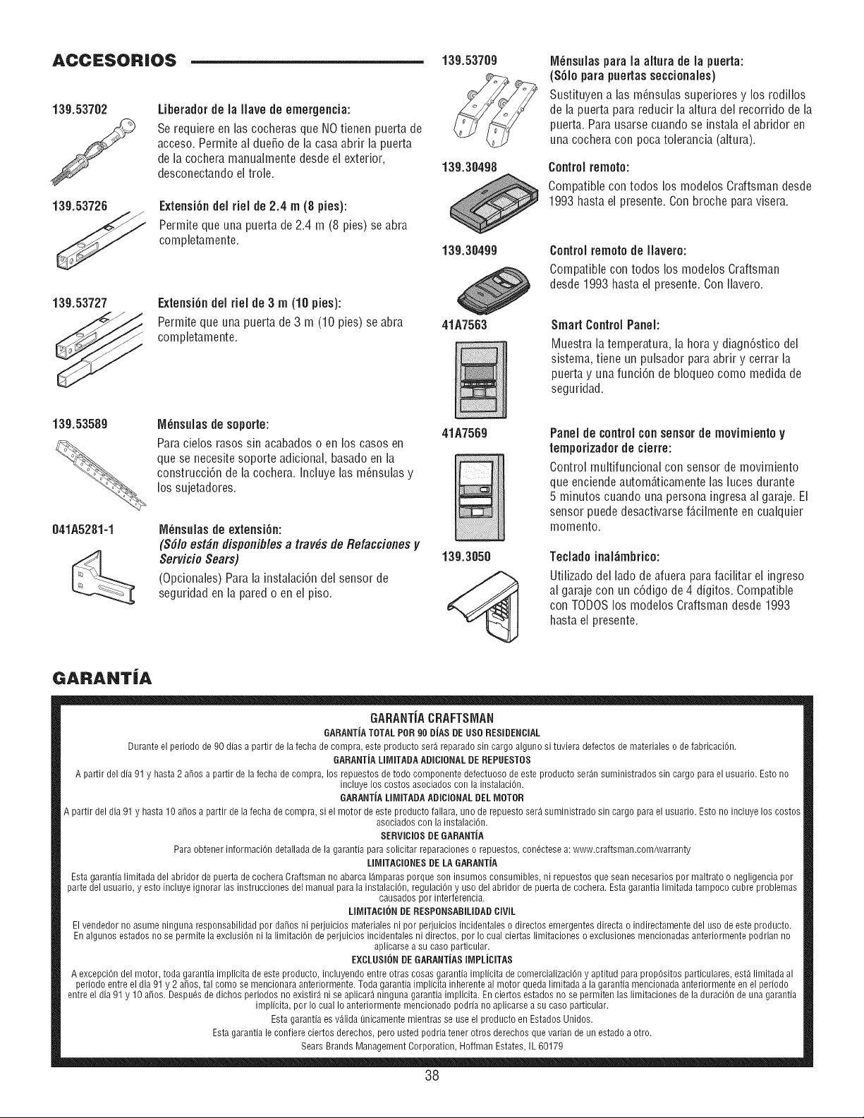
ACCESORIOS
139.53726
Liberador de la llave de emergencia:
Se requiere en las cocheras que NO tienen puerta de
acceso. Permite al dueSo de la casa abfir la puerta
de la cochera manualmente desde el exterior,
desconectando eltrole.
Extensi6n del riel de 2.4 m (8 pies):
Permite que una puerta de 2.4 m (8 pies) se abra
completamente.
139.53727
Extensi6n del rieJ de 3 m (10 pies):
Permite que una puerta de 3 m (10 pies) se abra
completamente.
139.53589
041A5281-1
M_nsuJas de soporte:
Para cielos rases sin acabados o en los cases en
que se necesite soporte adicional, basado en la
construcci6n de la co@era. Inciuye las m_nsuias y
los sujetadores.
M_nsulasde extensi6n:
(S61oestdn disponib/esa tray, s tie Refaccienes y
Servicio Sears)
(Opcionales) Para la instalaci6n del sensor de
seguridad en la pared o en el piso.
139.5370g
139.30498
139.30499
41A7563
41A7569
139.3050
IVl_nsulaspara la altura de la puerta:
(S61opara puertas seccionales)
Sustituyen a las m_nsulas superiores y los rodillos
de la puerta para reducir la altura del recorrido de la
puerta. Para usarse cuando se instalael abfidor en
una cochera con poca tolerancia (altura).
ControJ remote:
Compatible con todos los modelos Craftsman desde
1993 hasta el presente. Con broche para visera.
Control remote de llavero:
Compatible con todos los modelos Craftsman
desde 1993 hasta el presente. Con flavero.
Smart Control Paneh
Muestra la temperatura, la hera y diagn6stico del
sistema, tiene un pulsador para abrir y cerrar la
puerta y una funci6n de bloqueo come medida de
seguridad.
PaneJde controJcon sensorde movimiento y
tempofizador de cierre:
Control multifuncional con sensor de movimiento
que enciendeautom_,ticamentelas luces durante
5 minutes cuando una persona ingresa al garaje. EJ
sensor puede desactivarsef_,cilmenteen cualquier
memento.
Tedado inaJ_mbrico:
Utilizado del lade de afuera para facilitar el ingreso
al garaje con un c6digo de 4 digitos. Compatible
con TODOSlos modelos Craftsman desde 1993
hasta el presente.
GARANTiA
GARANTJACRAFTSMAN
GARANTJATOTAL POR90 DJAs DE USe RESIDENCIAL
Durante el periodo de 90 dias a partir de la fecha de compra, este producto ser_. reparado sin cargo alguno si tuviera defectos de materiales o de fabricaci6n.
GARANTJA LIMITADA ADICIONAL DE REPUESTOS
A partir del dia 91 y hasta 2 a_os a partir de la fecha de compra, los repuestos de todo componente defectuoso de este producto ser4n suministrados sin cargo para el usuario. Esto no
incluye los costos asociados con la instalaci6n.
GARANTJA LIMITADAADICIONAL DEL MOTOR
A partir del dia 91 y hasta 10 a_os a partir de la fecha de compra, si el motor de este producto fallara, uric de repuesto ser4 suministrado sin cargo para el usuario. Esto no incluye los costos
asociados con la instalaci6n.
SERVIClOSDE GARANTJA
Para obtener informaciOn detallada de la garantia para solicitar reparaciones o repuestos, con6ctese a: www.craftsman.com/warranty
LIMITACIONES DELA GARANTiA
Esta garantia limitada del abridor de puerta de cochera Craftsman no abarca 14mparasporque son insumos consumibles, ni repuestos que sean necesarios per maltrato o negligencia per
parte del usuario, y esto incluye ignorar las instrucciones del manual para la instalaci6n, regulaciOn y use del abridor de puerta de cochera. Esta garantia limitada tampoco cubre problemas
causados per interferencia.
LIMITACION DE RESPONSABILIDADCIVIL
El vendedor no asume ninguna responsabilidad per da_os ni perjuicios materiales ni per perjuicios incidentales o directos emergentes directa o indirectamente del use de este producto.
En algunos estados no se permite la exclusi6n ni la limitaciOn de perjuicios incidentales ni directos, per Io cual ciertas limitaciones o exclusiones mencionadas anteriormente podrian no
aplicarse a su case particular.
EXCLUSI{)NDE GARANTJAS IMPLJCITAS
A excepciOn del motor, toda garantia implicita de este producto, incluyendo entre otras cosas garantia implicita de comercializaci6n y aptitud para propOsitos particulares, est_ limitada al
periodo entre el dia 91 y 2 a_os, tal come se mencionara anteriormente. Toda garantia implicita inherente al motor queda limitada a la garantia mencionada anteriormente en el periodo
entre el dia 91 y 10 a_os. Despues de dichos periodos no existir4 ni se aplicar4 ninguna garantia implicita. En ciertos estados no se permiten las limitaciones de la duraciOn de una garantia
implicita, per Io cual Io anteriormente mencionado podria no aplicarse a su case particular.
Esta garantia es v_.lida Qnicamente mientras se use el producto en Estados Unidos.
Esta garantia le confiere ciertos derechos, pero usted podria tener otros derechos que varian de un estado a otro.
Sears Brands Management Corporation, Hoffman Estates, IL 60179
38

NOTAS
39

Your Home
For troubleshooting, product manuals and expert advice:
www.managemylife.com
For repair- in your home - of all major brand appliances,
lawn and garden equipment, or heating and cooling systems,
no matter who made it, no matter who sold it!
For the replacement parts, accessories and
owner's manuals that you need to do-it-yourself.
For Sears professional installation of home appliances
and items like garage door openers and water heaters.
1-800-4-MY-HOME ® (1-800-469-4663)
Call anytime, day or night (U.S.A. and Canada)
www.sears.com www.sears.ca
Our Home
For repair of carry-in items like vacuums, lawn equipment,
and electronics, call anytime for the location of your nearest
Sears Parts & Repair Service Center
1-800-488-1222 (U.S.A.) 1-800-469-4663 (Canada)
www.sears.com www.sears.ca
To purchase a protection agreement on a product serviced by Sears:
1-800-827-6655 (U.S.A.) 1-800-361-6665 (Canada)
Para pedir servicio de reparaciBn
a domicilio, y para ordenar piezas:
1-888-SU-HOGAR ®
(1-888-784-6427)
www.sears.com
Au Canada pour service en fran(_ais:
1-800-LE-FOYER Mc
(1-800-533-6937)
www.sears.ca
114A4366E
TM
@ Registered Trademark / Trademark of KCD IP, LLC in the United States, or Sears Brands, LLC in other countries
@ Marca Registrada/TM Marca de F_brica de KCD IP, LLC en Estados Unidos, o Sears Brands, LLC in otros paises
MC MS
Marque de commerce / Marque d@0s_e de Sears Brands, LLC
©2013 KCP IP, LLC