Loading ...
Loading ...

3
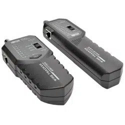
Locating a Short or Breakage in a Non-Powered Cable
RJ45 Wire Mapping
Notes:
• Set the volume from 6-8 when locating a short or breakage.
• Locating a short or breakage can only be performed on a non-powered cable.
• The included headphones can be used when in a noisy environment to ensure you are hearing
the tone from the Remote Probe Unit.
• Flip the light switch on the side of the Remote Probe Unit to turn on the light for use in dark
areas.
1. Flip the switch on the Main Tester to the Scan position. The Status LED will flash to
indicate the Main Tester is ready for operation.
2. Connect the included alligator clip adapter to the corresponding port on the Main
Tester.
• When locating a short, connect both alligator clips to the bare wires on the cable
being tested.
• When locating a breakage, connect the red alligator clip to one of the bare wires,
leaving the black alligator clip free.
3. Flip the switch on the Remote Probe Unit to the Scan position. The Power LED will
illuminate to indicate the Remote Probe Unit is ready for operation.
4. Run the probe of the Remote Probe Unit along the cable. The tone will sound,
indicating that the area where the probe is currently located is undamaged. Continue
running the probe along the cable until the tone stops, which will be the location of
the short or breakage.
1. Flip the switch on the Main Tester to the Test position. The Verify LED will flash to
indicate the Main Tester is ready for operation.
2. Flip the switch on the Remote Probe Unit to the Scan position. The Power LED will
illuminate to indicate the Remote Probe Unit is ready for operation.
3. Connect RJ45 cable from the RJ45 port of the Main Tester to the RJ45 port of the
Remote Probe Unit.
4. The Pin LEDs on the Main Tester and Remote Probe Unit will illuminate per below.
Note: When performing a Wire Mapping operation, pressing the SET button will change the
speed at which the LEDs flash.
• Good Cable – When a UTP cable is properly wired, the LEDs on both units will
flash in sequence from 1 through 8. For a good STP cable, the LEDs will flash in
sequence from 1 through 8, including G.
• Short – In the case of a short, the LED(s) of the pin(s) in which a short is present
will not illuminate on the Remote Probe Unit. The LEDs on the Main Tester unit will
all continue to illuminate.
• Open – In the case of an open pin, the LED(s) of the open pin(s) will remain off on
both the Main Tester and Remote Probe Unit.
15-11-220-9334E1.indd 3 12/9/2015 3:45:00 PM
Loading ...