Loading ...
Loading ...
Loading ...
7
Controls and Connectors
y [LIMIT] indicator
Indicates (lit in red) that the limiter is on when the output
voltage of the amplifier has exceeded the maximum level,
or when excessive integral power consumption is
detected. If this indicator stays lit, lower the input level.
u [SIGNAL] indicator
Indicates (lit in green) when an audio signal exceeding
the threshold has been detected.
i [PROTECTION] indicator
Indicates (lit in red) when the protection circuit is active.
The protection circuit will be activated and the speaker
outputs will be muted in the situations listed below.
• If amplifier overheating is detected
• If overcurrent is detected
• When turning the power on; the protection circuit will be
activated for a few seconds to prevent noise. The indi-
cator turns off when the power supply has started nor-
mally.
If the protection circuit has engaged, waiting until the
amplifier cools down or powering off and on again will
return to normal operation. If the unit does not return to
normal operation, please contact your Yamaha dealer.
o [POWER] indicator
Indicates (lit in green) when the [ / ] (power) (!5) switch
is turned on.
!0 [D-CONTOUR] indicator
Indicates (lit in yellow) when the [D-CONTOUR] switch
(!1) is set to [FOH/MAIN] or [MONITOR].
!1 [D-CONTOUR] switch
Selects one of the D-CONTOUR (Dynamic CONTOUR)
presets.
[FOH/MAIN]: Boosts the high and low frequency compo-
nents so that the frequency response is suitable for a
main speaker.
[MONITOR]: Reduces the low frequency range, which
could otherwise tend to be boomy if the speaker is set
directly on the floor. This enables you to hear mid and
high frequency ranges clearly when using as a floor
monitor.
[OFF]: Turns off D-CONTOUR. This is a generic frequency
response setting.
!2 [HPF] switch
Selects the cutoff frequency of the high pass filter. If you
set this switch to [120Hz] or [100Hz], the low frequency
components below each threshold will be cut. If you use
the unit alone, set this switch to [OFF]. If you plan to use
the unit along with a subwoofer, we recommend that you
set this switch to [120Hz] or [100Hz].
!3 Vent
The unit contains a cooling fan.
!4 [AC IN] socket
Connect the supplied power cord in the order below.
Before connecting the power cord, make sure that the
DHR power is turned off.
1. Insert the plug of the power cord into this socket.
2. Plug the other end of the cord into the AC outlet.
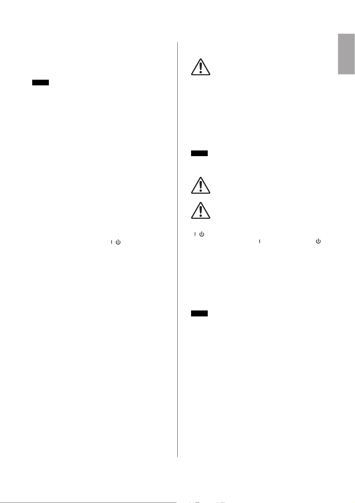
!5 [ / ] (power) switch
Turns the power supply on [ ] or sets it to standby [ ].
First, turn on the power of the connected sound source
(external device), then the unit. When turning off the
power, reverse the order by turning off the power of the
unit first and then the connected sound source (external
device).
Integral power consumption refers to the sum of power provided
to the speaker driver per unit time.
NOTE
CAUTION
Do not block the vents. This product has ventila-
tion holes at the rear to prevent the internal tem-
perature from becoming too high. Inadequate
ventilation can result in overheating, possibly
causing damage to the product(s), or even fire.
When removing the power cord, perform this procedure in
reverse order.
WARNING
Use only the supplied power cord.
CAUTION
Turn off the power before you connect or discon-
nect the power cord.
NOTICE
Even when the switch is in the standby position, a small
amount of electricity is still flowing to the unit.
• Rapidly turning the unit on and off in succession can cause it to
malfunction. After turning the unit off, wait for about 5 seconds
before turning it on again.
• If you are using multiple units, turn on the power to each unit
one by one. If you turn on the power to multiple units simultane-
ously, a temporary drop in the power voltage may occur, possi-
bly resulting in abnormal operation of the units.
NOTE
NOTE
Loading ...
Loading ...
Loading ...