Owner's Manual
Model No. 875.199330
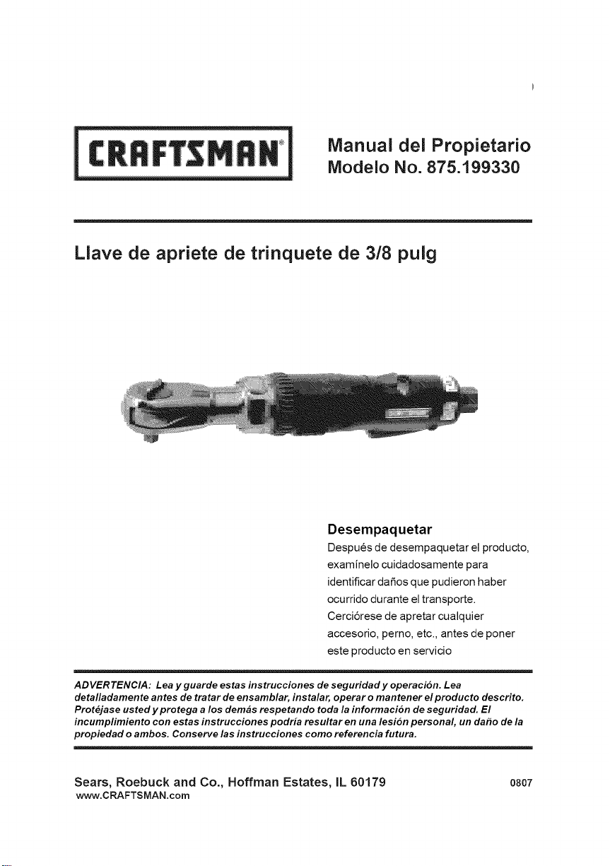
3/8-in. Ratchet Wrench
Unpacking
When unpacking this product, carefully
inspect for any damage that may have
occurred during transit. Make sure any
loose fittings, bolts, etc. are tightened
before putting this product into service.
WARNING: Please read and save these safety and operating instructions. Read carefully
before attempting to assemble, install, operate or maintain the product described.
Protect yourself and others by observing all safety information. Failure to comply with
instructions could result in personal injury and/or property damage! Retain instructions
for future reference.
Sears, Roebuck and Co., Hoffman Estates, IL 60179 o807
www.CRAFTSMAN.com
Owner's Manual Model No. 875.199330 Owner's Manual Mode! No. 875.199330
_, Features & Benefits
_, Specifications
_, Product Warranty
_, Compressor Requirements
Important Safety Instructions
_, Installation and Operation
_, Maintenance
_, Exploded View Drawing & Parts List
_, Troubleshooting
The Craftsman Model 875.199330 3/8"
Drive Ratchet Wrench is designed for
applications such as automotive repair,
general assembly, transmission teardown
and maintenance. Features include a lever
throttle for speed control and low profile
ratchet head height (without socket) for
use in close-quarter applications. 360°
swivel exhaust directs air away from
operator.
Drive size ........................................... 3/8"
Free speed (No Load) .............. 160 RPM
Max Torque ................................ 50 ft. Ibs.
Weight ........................................... 2.3 Ibs.
Overall length ..................................... 10"
Average air consumption ........ 4.0 SCFM
Recommended hose size .......... 3/8" I.D.
Air inlet ....................................... 1/4" NPT
Maximum Air Pressure .................. 90 PSI
ONE YEAR FULL WARRANTY ON
CRAFTSMAN TOOL
If this Craftsman tool fails to give complete
satisfaction within one year from the date
of purchase, RETURN IT TO ANY SEARS
STORE OR OTHER CRAFTSMAN
OUTLET IN THE UNITED STATES FOR
FREE REPLACEMENT.
If this Craftsman tool is ever used for
commercial or rental purposes, this
warranty applies for only 90 days from the
date of purchase.
This warranty does not include
expendable parts, such as lamps,
batteries, bits or blades.
This warranty gives you specific legal
rights, and you may also have other rights
which vary from state to state.
Sears, Roebuck and Co.,
Hoffman Estates, IL 60179
Light Use - 17 Gallon
Typical Use - 26 Gallon
Heavy Use - 33 Gallon Professional
Read Operating Instructions
Please become familiar with all the
instructions and warnings before
operating any pneumatic tool,
Always Wear Approved Eye Protection
Impact resistant eye protection should
meet or exceed the standards set forth in
ANSI Z87.1, Occupational and
Educational Eye and Face Protection.
Look for marking Z87.1 on your eye
protection to ensure that it is an approved
style.
Hearing Protection is Recommended
Hearing protection should be used when
the noise level exposure equals or
exceeds an 8 hour time-weighted average
sound level of 85dBA. Process noise,
reflective surfaces, other tools being
operated nearby, all add to the noise level
in a given work area. If you are unable to
determine your noise level exposure, we
recommend the use of hearing protection.
Avoid Prolonged Exposure to Vibration
Pneumatic tools can vibrate during use.
Prolonged exposure to vibration or very
repetitive hand and arm movements can
cause injury. Discontinue the use of any
tool if you experience tingling, numbness,
discomfort or pain in your hands or arms.
You should consult your physician before
resuming use of tool.
90 PSI Maximum
This tool is designed to operate at an air
pressure of 90 pounds per square inch
gauge pressure (90 PSI) maximum, at the
tool. Use of higher air pressure can, and
may cause injury. Also, the use of higher
air pressure places the internal
components under loads and stresses
they were not designed for, causing
premature tool failure.
California Prop 65
Some dust created by power sanding,
sawing, grinding, drilling and other
construction activities contains
chemicals known to cause cancer, birth
defects or other reproductive harm.
Some examples of these chemicals are:
Lead from lead based paint, crystalline
silica from bricks and cement and other
masonry products, arsenic and
chromium from chemically-treated
lumber.
Your risk from those exposures varies,
depending on how often you do this
type of work. To reduce your exposure
to these chemicals: work in a well
ventilated area, and work with approved
safety equipment, such as dust masks
that are specifically designed to filter
out microscopic particles.
ENG-2 ENG-3

Owner's Manual Model No. 875.199330 Owner's Manual Mode! No. 875.199330
Disconnect the air tool from air supply
before changing tools or attachments,
servicing and during non-operation.
Do not wear loose fitting clothing,
scarves, or neck ties in work area. Loose
clothing may become caught in moving
parts and result in serious personal injury.
Do not wear jewelry when operating
any tool. Jewelry may become caught in
moving parts and result in serious
personal injury.
Do not depress trigger when connecting
the air supply hose.
Never trigger the tool when not applied
to a work object.
Attachments must be securely
attached. Loose attachments can cause
serious injury.
Protect air lines from damage or
puncture.
Never point an air tool at oneself or any
other person. Serious injury could occur.
Check air hoses for weak or worn
conditions before each use. Make sure all
connections are secure.
Use attachments designed for use with
air powered tool. Always examine
accessories before mounting for chips,
cracks, or signs of damage.
Never use mounted points or other
accessories that have been dropped or
exposed to water, solvent or extreme
temperature changes. It is a good practice
to operate the tool in a protected
enclosure for one minute after mounting
any accessory.
Always use accessories with an RPM
rating that meets or exceeds the tool
RPM rating.
Never carry a tool by the hose or pull
the hose to move the tool or a
compressor. Keep hoses away from
heat, oil and sharp edges. Replace any
hose that is damaged, weak or worn.
Release all pressure from the system
before attempting to install, service,
relocate or perform any maintenance.
Keep all nuts, bolts and screws tight
and ensure equipment is in safe working
condition.
Inhalation hazard: Abrasive tools, such
as grinders, sanders and cut-off tools
generate dust and abrasive materials
which can be harmful to human lungs
and respiratory system. Always wear
MSHA/NIOSH approved, properly fitting
face mask or respirator when using
such tools.
Some materials such as adhesives and
tar, contain chemicals whose vapors
could cause serious injury with
prolonged exposure. Always work in a
clean, dry, well ventilated area.
Tools which contain moving elements,
or drive other moving tools, such as
grinding wheels, sockets, sanding
discs, etc., can become entangled in
hair, clothing, jewelry and other loose
objects, resulting in severe injury.
Never wear loose fitting apparel which
contains loose straps or ties, that could
become tangled in moving parts of the
tool. Remove any jewelry, watches, etc.,
which might become caught by the
tool. Keep hands away from moving
parts. Tie up or cover long hair.
Tools which cut, shear, drill, staple,
punch, chisel, etc. are capable of
causing serious injury. Keep the
working part of the tool away from
hands and body.
After an air tool has been lubricated, oil
will discharge through the exhaust port
during the first few seconds of
operation. Thus, the exhaust port must
be covered with a towel before applying
air pressure.
Always make sure that tool accessories
meet or exceed the tools reccomended
output.
improperly maintained tools and
accessories can cause serious injury.
Maintain the tool with care. A properly
maintained tool, with sharp cutting
edges, reduces the risk of binding and
is easier to control.
There is a risk of bursting if the tool is
damaged. Check for misallgnment or
binding of moving parts, breakage of
parts and any other condition that
affects the tool's operation. If damaged,
have the tool serviced before using.
Disconnect tool from air supply before
servicing or changing sockets.
When tightening, do not torque down
the nuts or bolts with the ratchet as
typically done with a hand wrench. This
can damage the tool by breaking parts
in the ratchet mechanism.
ENG-4 ENG-5
Owner's Manual Model No. 875.199330 Owner's Manual Mode! No. 875.199330
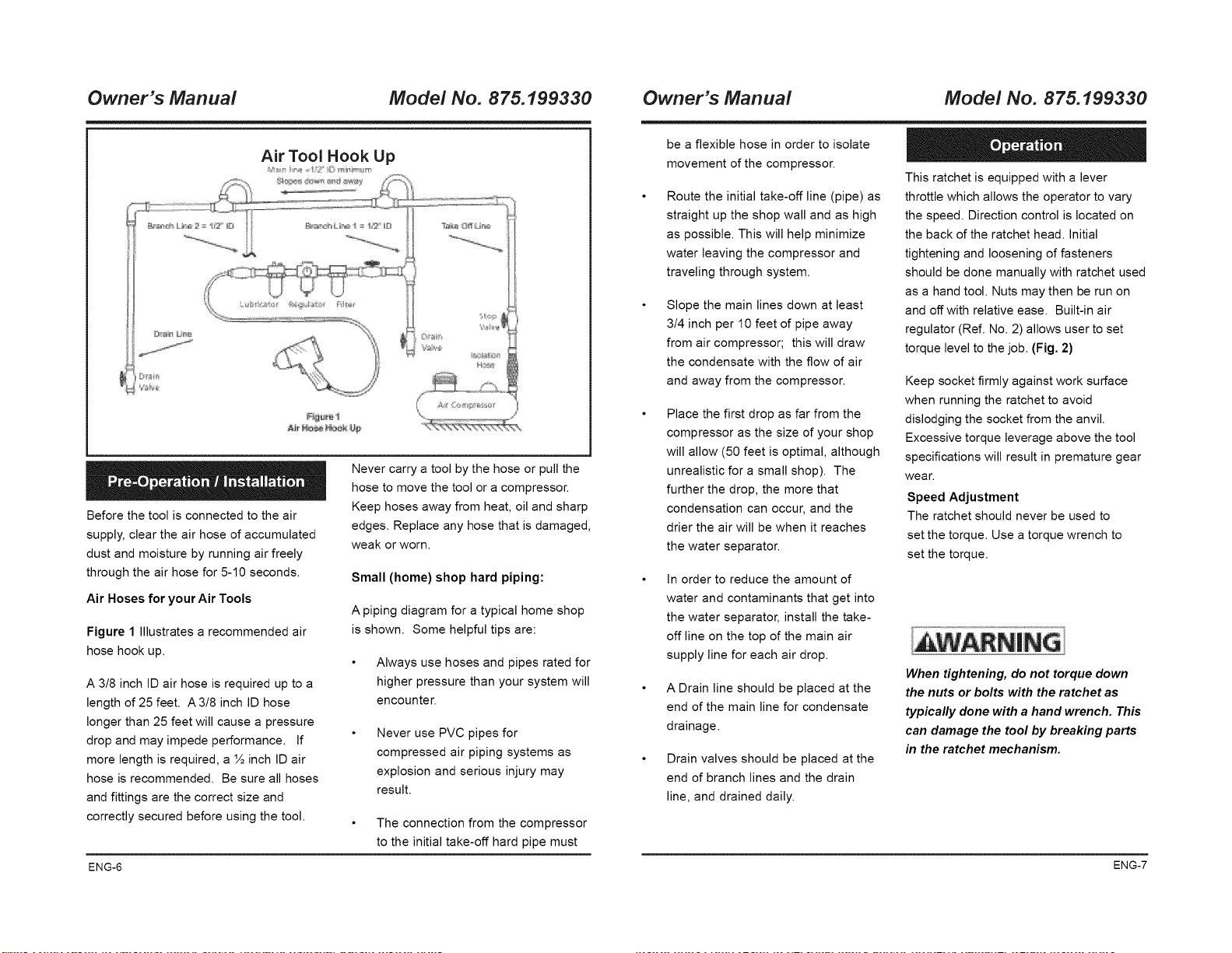
Air Tool Hook Up
Before the tool is connected to the air
supply, clear the air hose of accumulated
dust and moisture by running air freely
through the air hose for 5-10 seconds.
Air Hoses for your Air Tools
Figure 1 Illustrates a recommended air
hose hook up.
A 3/8 inch ID air hose is required up to a
length of 25 feet. A 3/8 inch ID hose
longer than 25 feet will cause a pressure
drop and may impede performance. If
more length is required, a ½ inch ID air
hose is recommended. Be sure all hoses
and fittings are the correct size and
correctly secured before using the tool.
Never carry a tool by the hose or pull the
hose to move the tool or a compressor.
Keep hoses away from heat, oil and sharp
edges. Replace any hose that is damaged,
weak or worn.
Small (home) shop hard piping:
A piping diagram for a typical home shop
is shown. Some helpful tips are:
Always use hoses and pipes rated for
higher pressure than your system will
encounter.
Never use PVC pipes for
compressed air piping systems as
explosion and serious injury may
result.
The connection from the compressor
to the initial take-off hard pipe must
be a flexible hose in order to isolate
movement of the compressor.
Route the initial take-off line (pipe) as
straight up the shop wall and as high
as possible. This will help minimize
water leaving the compressor and
traveling through system.
Slope the main lines down at least
3/4 inch per 10 feet of pipe away
from air compressor; this will draw
the condensate with the flow of air
and away from the compressor.
Place the first drop as far from the
compressor as the size of your shop
will allow (50 feet is optimal, although
unrealistic for a small shop). The
further the drop, the more that
condensation can occur, and the
drier the air will be when it reaches
the water separator.
In order to reduce the amount of
water and contaminants that get into
the water separator, install the take-
off line on the top of the main air
supply line for each air drop.
A Drain line should be placed at the
end of the main line for condensate
drainage.
Drain valves should be placed at the
end of branch lines and the drain
line, and drained daily.
This ratchet is equipped with a lever
throttle which allows the operator to vary
the speed. Direction control is located on
the back of the ratchet head. Initial
tightening and loosening of fasteners
should be done manually with ratchet used
as a hand tool. Nuts may then be run on
and off with relative ease. Built-in air
regulator (Ref. No. 2) allows user to set
torque level to the job. (Fig. 2)
Keep socket firmly against work surface
when running the ratchet to avoid
dislodging the socket from the anvil.
Excessive torque leverage above the tool
specifications will result in premature gear
wear.
Speed Adjustment
The ratchet should never be used to
set the torque. Use a torque wrench to
set the torque.
When tightening, do not torque down
the nuts or bolts with the ratchet as
typically done with a hand wrench. This
can damage the tool by breaking parts
in the ratchet mechanism.
ENG-6 ENG-7
Owner's Manual Model No. 875.199330 Owner's Manual Mode! No. 875.199330
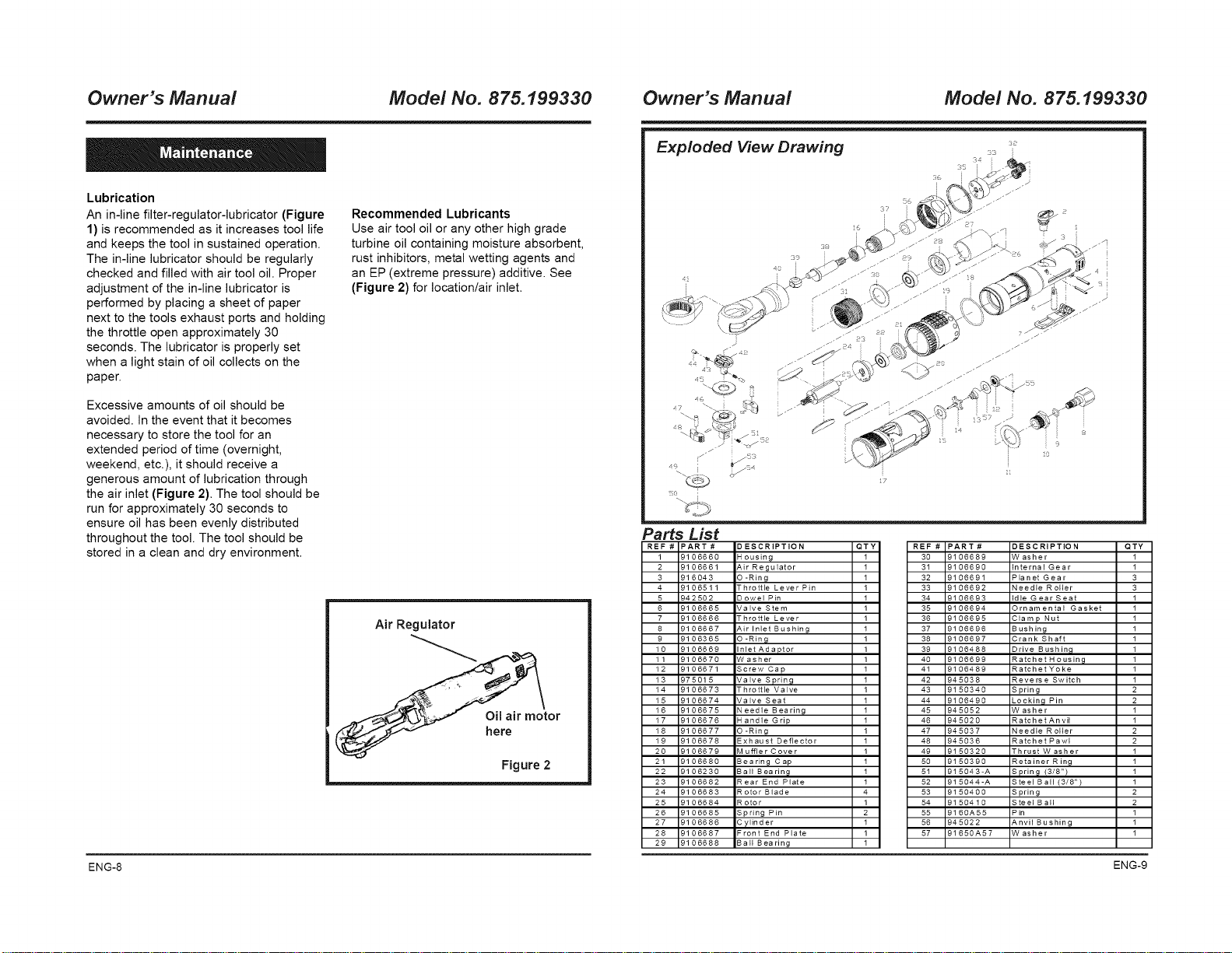
Lubrication
An in-line filter-regulator-lubricator (Figure
1) is recommended as it increases tool life
and keeps the tool in sustained operation.
The in-line lubricator should be regularly
checked and filled with air tool oil. Proper
adjustment of the in-line lubricator is
performed by placing a sheet of paper
next to the tools exhaust ports and holding
the throttle open approximately 30
seconds. The lubricator is properly set
when a light stain of oil collects on the
paper.
Excessive amounts of oil should be
avoided. In the event that it becomes
necessary to store the tool for an
extended period of time (overnight,
weekend, etc.), it should receive a
generous amount of lubrication through
the air inlet (Figure 2). The tool should be
run for approximately 30 seconds to
ensure oil has been evenly distributed
throughout the tool. The tool should be
stored in a clean and dry environment.
Recommended Lubricants
Use air tool oil or any other high grade
turbine oil containing moisture absorbent,
rust inhibitors, metal wetting agents and
an EP (extreme pressure) additive. See
(Figure 2) for location/air inlet.
Air Regulator
or
ere
Figure 2
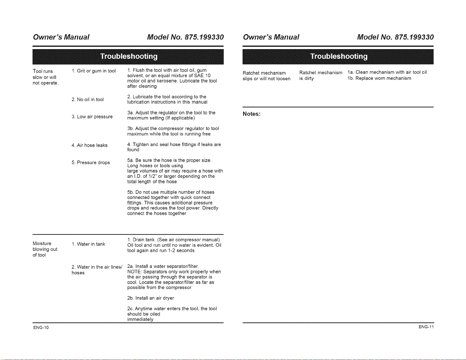
Exploded View Drawing
2
Parts List
REF# PART# DESCRIPTION QTY
1 8106660 _ ousing 1
2 8106661 _dr Regulator 1
3 816043 D-Ring 1
4 8106511 Throttle Lever Pin 1
5 942502 Dowel Pin 1
6 8106665 dalve Stem 1
7 8106666 Throttle Lever 1
8 8106667 _dr Inlet Bushing 1
9 8106365 D-Ring 1
10 8106669 nlet Adaptor 1
11 8106670 Hasher 1
12 8106671 Screw Cap 1
13 875015 dalve Spring 1
14 8106673 Throttle Valve 1
15 8106674 dalve Seat 1
16 8106675 _ eedle Bearing 1
17 8106676 4andle Grip 1
18 8106677 D-Ring 1
19 8106678 Exhaust Deflector 1
20 8106679 Vluffler Cover 1
21 8106680 8earing Cap 1
22 8106230 3all Bearing 1
23 8106682 Rear End Plate 1
24 8106683 Rotor Blade 4
25 8106684 Rotor 1
26 8106685 Spring Pin 2
27 8106686 £ylinder 1
28 8106687 =font End Plate 1
29 8106688 3all Bearing 1
REF
30
3I
32
33
34
35
36
37
38
39
40
41
42
43
44
45
46
47
48
49
50
5I
52
53
54
55
56
57
PART #
9106688
9106680
9106681
9106682
9106683
9106694
9106695
9106696
9106697
9106488
9106699
9106489
945038
9150340
9106490
945052
945020
945037
945036
9150320
9150390
915043-A
9I 5044-A
9150400
9150410
9160A55
945022
91650A57
DESCRIPTION
JV asher
internal Gear
=la n et Gear
_ eedle Roller
die G ear Seat
Drnamental Gasket
31amp Nut
8ushing
3rank Shaft
Drive B ushin,q
Ratch et H ousing
Ratchet Yoke
Reverse Switch
Spring
_o ckin,q Pin
JV asher
Ratchet Anvil
Meedle Roller
Ratchet Pawl
Thrust W asher
Retainer Ring
Spring (3/8" /
SteeJ BaH (3/8")
Spring
Steel B all
= in
_,nvil Bushing
JV asher
QTY
1
1
88
11
1
11
11
1
19
1
99
11
1
19
1
1
ENG-8 ENG-9
Owner's Manual Model No. 875.199330
Tool runs
slow or will
not operate.
1. Grit or gum in tool
1. Flush the tool with air tool oil, gum
solvent, or an equal mixture of SAE 10
motor oil and kerosene. Lubricate the tool
after cleaning
2. No oil in tool
2. Lubricate the tool according to the
lubrication instructions in this manual
3. Low air pressure
3a. Adjust the regulator on the tool to the
maximum setting (If applicable)
3b. Adjust the compressor regulator to tool
maximum while the tool is running free
4. Air hose leaks
4. Tighten and seal hose fittings if leaks are
found
5. Pressure drops
5a. Be sure the hose is the proper size.
Long hoses or tools using
large volumes of air may require a hose with
an I.D. of 1/2" or larger depending on the
total length of the hose
5b. Do not use multiple number of hoses
connected together with quick connect
fittings. This causes additional pressure
drops and reduces the tool power. Directly
connect the hoses together
Owner's Manual Model No. 875.199330
Ratchet mechanism Ratchet mechanism la. Clean mechanism with air tool oil
slips or will not loosen is dirty lb. Replace worn mechanism
Notes:
Moisture
blowing out
of tool
ENG-10
1. Water in tank
1. Drain tank. (See air compressor manual).
Oil tool and run until no water is evident. Oil
tool again and run 1-2 seconds
2. Water in the air lines/
hoses
2a. Install a water separator/filter.
NOTE: Separators only work properly when
the air passing through the separator is
cool. Locate the separator/filter as far as
possible from the compressor
2b. Install an air dryer
2c. Anytime water enters the tool, the tool
should be oiled
immediately
ENG-11
Manual del Propietario
Modelo No. 875.199330
Llave de apriete de trinquete de 3/8 pulg
Desempaquetar
Despues de desempaquetar el producto,
examinelo cuidadosamente para
identificar daSos que pudieron haber
ocurrido durante el transporte.
Cerci6rese de apretar cualquier
accesorio, pemo, etc., antes de poner
este producto en servicio
ADVERTENCIA: Lea y guarde estas instrucciones de seguridad y operaci6n. Lea
detalladamente antes de tratar de ensamblar, instalar, operar o mantener el producto descrito.
Prot_jase usted y protega a los demas respetando toda la informaci6n de seguridad. El
incumplimiento con estas instrucciones podria resultar en una lesi6n personal, un daho de la
propiedad o ambos. Conserve/as instrucciones como referencia futura.
Sears, Roebuck and Co., Hoffman Estates, IL 60179 o807
www.CRAFTSMAN.com
Manual del Propietario Modelo No. 875.199330 Manual del Propietario Modelo No. 875.199330
Caracteristicas y operaci6n
Especificaciones
Garantia del producto
Requisites del compresor
Instrucciones de seguridad importantes
Instalaci6n y operaci6n
Mantenimiento
Piano de vista despiezada y lista de
piezas
Localizaci6n y soluci6n de fallas
La Ilave de trinquete con mando de 3/8
pulgada Craftsman, Modelo
875.199330,esta dise_ada para las
aplicaciones come la reparaci6n de
autom6viles, el ensamble en general, el
desmontaje y el mantenimiento de la
transmisi6n. Entre las caracteristicas se
incluyen un acelerador con palanca para el
control de la velocidad y altura del cabezal
del trinquete de bajo perfil (sin caquillo) para
usar en las aplicaciones donde se trabaja
bien cerca. El escape giratorio de 360° aleja
el aire del operario.
GARANTiA COMPLETA POR UNANO DE
HERRAMIENTACRAFTSMAN
Siesta herramienta Craftsman falla en
proporcionarle una satisfacci6n completa
dentro de un a_o a partir de su fecha de
compra, DEVUELVALAA CUALQUIER
TIENDASEARS U OTROS ESTABLECl-
MIENTOS DE SEARS EN LOS ESTADOS
UNIDOS, PARA UN REEMPLAZO GRATIS.
Siesta herramienta Craftsman alguna
vez se usa para fines comerciales o de
alquiler, esta garantia se aplica
solamente per 90 dias a partir de la fecha
de compra.
Esta garantia no incluye las piezas
consumibles, come lamparas, baterias,
brocas u hojas.
Esta garantia le proporciona derechos
legales especificos, y usted puede tener
tambien otros derechos que varian de
estado a estado.
Sears, Roebuck and Co.,
Hoffman Estates, IL60179, EE.UU.
Tamar_o del accionador ............................... 3/8"
Velocidad libre (sin carga) ................... 160 RPM
Par terser max ......................... 50 pies per libra
Peso .................................................... 2.3 libras
Longitud total ................................................ 10"
Consume promedio de aire ............... 4.0 SCFM
Tamar_o recomendado
para la manguera .............. Di& int. de 3/8 pulg
Admisi6n de aire .......................... 1/4 pulg NPT
Presi6n de aire maxima .......................... 90 PSI
Pocouse -17 galones
Use regular -26 galones
Usepesado -33 galones profesional
Lea las instrucciones de operacion
Familiaricese con todas las instrucciones y
advertencias antes de usar cualquiera
herramienta neumatica.
Use siempre proteccion adecuada para
los ojos
La protecci6n ocular resistente al impacto
debera satisfacer o superar las normas
especificadas enANSI Z87. t, bajo el titulo
Protecci6n ocular y facial ocupacional y
educativa. Busque la marca Z87.1 en su
protector de los ojos para asegurar que es
un estilo aprobado.
90 PSIG MAXIMO
Esta herramienta esta dise_ada para
operar a una presi6n neumatica maxima de
indicador de 90 libras per pulgada cuadrada
(90 PSI), en la herramienta. El use de una
presi6n de aire mayor puede y podra
causar lesiones. Tambien, el use de una
presi6n neumatica mayor somete a los
componentes internes a cargas y tensiones
para las cuales no fueron dise_ados,
causando una falla prematura de la
herramienta.
Se recomienda proteccion de los oidos
La protecci6n de los oidos debe usarse
cuando la exposici6n de nivel de sonido
iguala o excede un nivel promedio
ponderado per tiempo, de 8 horas, de
85dBA. El ruido del proceso, superficies
reflectoras, otras herramientas operadas
en la cercania, todos agregan al nivel de
ruido en un &rea determinada de trabajo. Si
no es posible determinar la exposici6n al
nivel de ruido, se recomienda usar
protecci6n auditiva.
Evite la exposicion prolongada a la
vibracion.
Las herramientas neumaticas pueden
vibrar durante su use. La exposici6n
prolongada alas vibraciones o los
movimientos muy repetidos de manes y
brazes pueden causar lesiones. Interrumpa
el use de cualquier herramienta si
experimenta cosquilleo, adormecimiento,
malestar o dolor en las manes o brazes.
Debera consultar con su medico antes de
seguir usando la herramienta.
Proyecto de ley 65 de California
Algunos pelves creados per el lijado,
aserrado, desgastado, taladrado y otras
actividades de construcci6n contienen
substancias quimicas conocidas come
causantes de c_ncer, defectos de
nacimiento u otras lesiones en el
sistema de reproducci6n. Algunos
ejemplos de esas sustancias quimicas
sent
PIomo de pinturas que contienen plomo
silice cristafino de ladrillos, cemento y
otros productos de alba#ileria ars_nico
y creme de madera quimicamente
tratada
Su riesgo de esas exposiciones varia,
dependiendo de cuan a menudo usted
electra este tipo de trabajo. Para reducir
su exposici6n a estos materiales: trabaje
en un _rea bien ventilada y con los
equipos de protecci6n aprobados, come
m_scaras de polvo que est_n
especificamente dise#adas para ffltrar
particulas microsc6picas.
SPA-2 SPAG
Manual del Propietario Modelo No. 875.199330 Manual del Propietario Modelo No. 875.199330
Desconecte la herramienta del
suministro de aire antes de cambiar
herramientas o accesorios, darle servicio o
durante el tiempo que no este funcionando.
No use ropa suelta, bufandas o corbatas
en el area de trabajo. La ropa suelta podria
quedar atrapada en las piezas en
movimiento y resultar en una lesi6n
personal grave.
No use joyas mientras usa la
herramienta. Lasjoyas podrian quedar
atrapadas en las piezas en movimiento y
resultar en una lesi6n personal grave.
No presione el disparador cuando este
conectando la manguera de suministro de
aire.
No apriete el disparador de la
herramienta cuando no se aplique a un
objeto de trabajo.
Los aeeesorios deben aeoplarse de
forma segura. Los accesorios sueltos
pueden causar una lesi6n grave.
Protega las lineas de aire eontra los
dafios y punciones.
Nunca apunte una herramienta
neumatiea a sus propia persona ni a
ninguna otra persona. Podria ocurrir una
lesi6n grave.
Revise las mangueras de aire en busca
de eondieiones d_biles o de desgaste
antes de cada uso. AsegQrese de que todas
las conexiones esten bien afianzadas.
Use accesorios dise#ados para utilizar
con ia herramienta el#ctrica neumatica,
Siempre examine los accesorios antes
del montaje en busca de astiiias, grietas
o indicios de algtJn da#o,
Nunca use puntos montados u otros
accesorios que se han caido o se han
expuesto al agua, disolventes o cambios
extremos de temperatura. Es bueno usar la
herramienta en un alojamiento protegido por
un minuto despu_s de montade cualquier
accesorio.
Siempre use accesorios ciasificados
para revoiuciones por minutos (RPM)
que cumplan o excedan con ia
ciasificaci6n de RPM de ia herramienta.
Nunca Ileve una herramienta por la
manguera ni nunca tire de la manguera
para mover una herramienta o un
compresor. Mantenga las mangueras
alejadas del calor, aceite y bordes
afilados. Reemplace cualquier manguera
que est# da#ada, d#bil o desgastada.
Libere toda la presion del sistema antes
de tratar de instalar, dar servicio,
reubicar o realizar cualquier
mantenimiento.
Mantenga todas las tuercas, pernos y
tornillos apretados, y asegure que el
equipo este en condiciones de trabajo
seguras.
Peligro de inhalaci6n: Las herramientas
abrasivas, como molinillos, lijadoras y
herramientas de core, generan polvo y
materiales abrasivos que pueden ser
da#inos para los pulmones y el sistema
respiratorio de las personas. Siempre
use una m#scara facial o respirador con
buen ajuste, que est@ aprobado pot
MSHA/NIOSH, cuando utilice tales
herramientas.
Algunos materiales, como adhesivos y
alquitr#n, continen compuestos
quimicos cuyos vapores podrian causar
una grave lesi6n con la exposici6n
prolongada. Trabaje siempre en un #rea
fimpia, seca y bien ventilada.
Las herramientas que cortan, cizailan,
barrenan, apilan, punzonan, cincelan,
etc. pueden causar una lesi6n grave.
Mantenga la pieza de trabajo de la
herramienta alejada de las manos y el
cuerpo.
Las herramientas que contienen piezas
m6viles, o que impulsan a otras
herramientas m6viies, como ruedas
amoiadoras, cubos, discos iijadores,
etc., pueden enredarse en el pelo, ropa,
joya y otros objetos sueltos, resultando
en una grave iesi6n.
Nunca use ropa suelta que contengan
correas o corbatas, que podrian quedar
atrapados en ias piezas m6viies de la
herramienta. Quitese cuaiquierjoya,
reloj, etc. que podria ser atrapado pot ia
herramienta. Mangenga las manos
aiejadas de ias piezas m6viles. Rec6jase
o c_brase elpelo.
Despu_s de lubricar la herramienta
neum#tica, el aceite ser# descargado
pot el puerto de escape durante los
primeros segundos de operaci6n. Por
Io tanto, el puerto de escape debe estar
tapado con una toafla antes de aplicar
presi6n de aire.
Siempre asegt_rese de que los
accesorios de la herramienta cumplan o
excedan la salida recomendada para las
herramientas.
Las herramientas y accesorios mai
mantenidos pueden causar una lesi6n
grave. D#le mantenimiento a la
herramienta con cuidado. Estas
herramientas de corte con el
mantenimiento adecuado, con bordes
de corte afilados, reducen el riesgo de
atasco y son m_s f_ciies de controlar.
Antes de prestar servicio o cambiar los
casquiilos desconecte ia herramienta del
suministro de aire.
Si la herramienta est# da#ada existe el
peligro de que explote repentinamente.
Revise los desajustes o atascos de las
piezas m6vfles, roturas de las piezas y
cualquier otra condici6na que afecte el
funcionamiento de la herramienta. Si la
misma est# da#ada, haga que se led#
mantenimiento antes de usarla.
Cuando est_n apretadas, no apriete mas
las tuercas y los persnos con una Ilave
como se hace tipicamente con una Ilave
de mano. Esto puede da#ar la
herramienta rompiendo las piezas del
mecanismo de trinquete.
SPA4 SPA4
Manual del Propietario
Modelo No. 875.199330
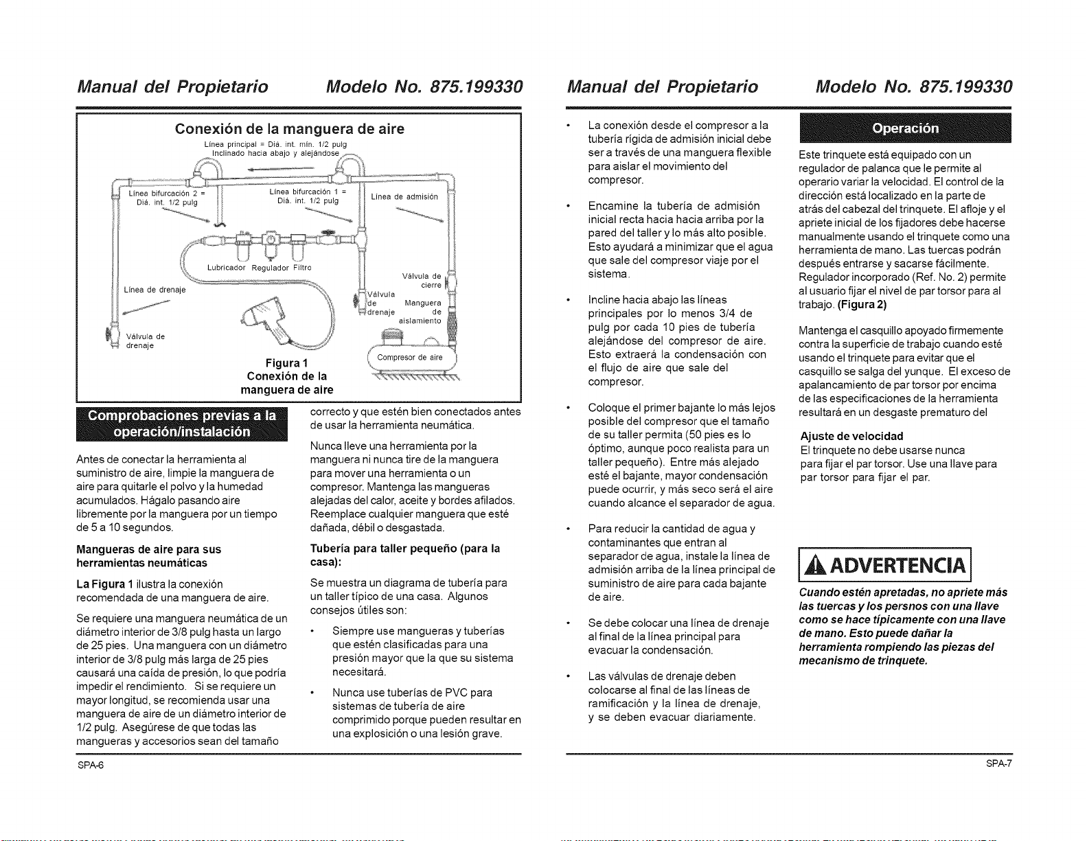
Cone×i6n de la manguera de aire
Linea principal = Di& int rain. 1/2 pulg
Inclinado hacia abajo y alejandose
Linea bifurcaci6n 2 = Linea bifurcaci6n 1 =
Dia. int. 1/2 pulg Di& int. 1/2 pulg Linea de admision
Lubricador Regulador Filtro
Linea de drenaje
Valvula de
drenaje
Figura 1
Conexion de la
manguera de aire
Antes de conectar la herramienta al
suministro de aire, limpie la manguera de
aire para quitarle el polvo y la humedad
acumulados. Hagalo pasando aire
libremente por la manguera por un tiempo
de 5 a 10 segundos.
Mangueras de aire para sus
herramientas neumaticas
La Figura 1 ilustra la conexi6n
recomendada de una manguera de aire.
Se requiere una manguera neumatica de un
diametro interior de 3/8 pulg hasta un largo
de 25 pies. Una manguera con un diametro
interior de 3/8 pulg mas larga de 25 pies
causara una caida de presi6n, Ioque podria
impedir el rendimiento. Si se requiere un
mayor Iongitud, se recomienda usar una
manguera de aire de un diametro interior de
1/2 pulg. AsegQrese de que todas las
mangueras y accesorios sean del tamafio
Valvula de
Jalvula
Manguera
je de
aisiamiento
correcto yque esten bien conectados antes
de usar la herramienta neum&tica.
Nunca Ileve una herramienta por la
manguera ni nunca tire de la manguera
para mover una herramienta o un
compresor. Mantenga las mangueras
alejadas del calor, aceite y bordes afilados.
Reemplace cualquier manguera que este
dafiada, debil o desgastada.
Tuberia para taller peque_o (para la
casa):
Se muestra un diagrama de tuberia para
un taller tipico de una casa. Algunos
consejos Otiles son:
Siempre use mangueras ytuberias
que esten clasificadas para una
presi6n mayor que la que su sistema
necesitar&.
Nunca use tuberias de PVC para
sistemas de tuberia de aire
comprimido porque pueden resultar en
una explosici6n o una lesi6n grave.
Manual del Propietario
Modelo No. 875.199330
La conexi6n desde el compresor a la
tuberia rigida de admisi6n inicial debe
ser a traves de una manguera flexible
para aislar el movimiento del
compresor.
Encamine la tuberia de admisi6n
inicial recta hacia hacia arriba por la
pared del taller y Io m&s alto posible.
Esto ayudar& a minimizar que el agua
que sale del compresor viaje por el
sistema.
Incline hacia abajo las lineas
principales por Io menos 3/4 de
pulg por cada 10 pies de tuberia
alej&ndose del compresor de aire.
Esto extraer& la condensaci6n con
el flujo de aire que sale del
compresor.
Coloque el primer bajante Io mas lejos
posible del compresor que el tamafio
de su taller permita (50 pies es Io
6ptimo, aunque poco realista para un
taller pequefio). Entre mas alejado
este el bajante, mayor condensaci6n
puede ocurrir, y mas seco sera el aire
cuando alcance el separador de agua.
Este trinquete esta equipado con un
regulador de palanca que le permite al
operario variar la velocidad. El control de la
direcci6n esta Iocalizado en la parte de
atras del cabezal del trinquete. El afloje y el
apriete inicial de los fijadores debe hacerse
manualmente usando el trinquete como una
herramienta de mano. Las tuercas podran
despues entrarse y sacarse facilmente.
Regulador incorporado (Ref. No. 2) permite
al usuario fijar el nivel de par torsor para al
trabajo. (Figura 2)
Mantenga el casquillo apoyado firmemente
contra la superficie de trabajo cuando este
usando el trinquete para evitar que el
casquillo se salga del yunque. El exceso de
apalancamiento de par torsor por encima
de las especificaciones de la herramienta
resultara en un desgaste prematuro del
Ajuste de velocidad
El trinquete no debe usarse nunca
para fijar el par torsor. Use una Ilave para
par torsor para fijar el par.
Para reducir la cantidad de agua y
contaminantes que entran al
separador de agua, instale la linea de
admisi6n arriba de la linea principal de
suministro de aire para cada bajante
de aire.
Se debe colocar una linea de drenaje
al final de la linea principal para
evacuar la condensaci6n.
Las v&lvulas de drenaje deben
colocarse al final de las lineas de
ramificaci6n y la linea de drenaje,
y se deben evacuar diariamente.
ADVERTENC|A i
Cuando est_n apretadas, no apriete mas
las tuercas y los persnos con una Ilave
como se hace tipicamente con una Ilave
de mano. Esto puede da#ar la
herramienta rompiendo las piezas del
mecanismo de trinquete.
SPA4 SPA-7
Manual del Propietario Modelo No. 875.199330 Manual del Propietario Modelo No. 875.199330
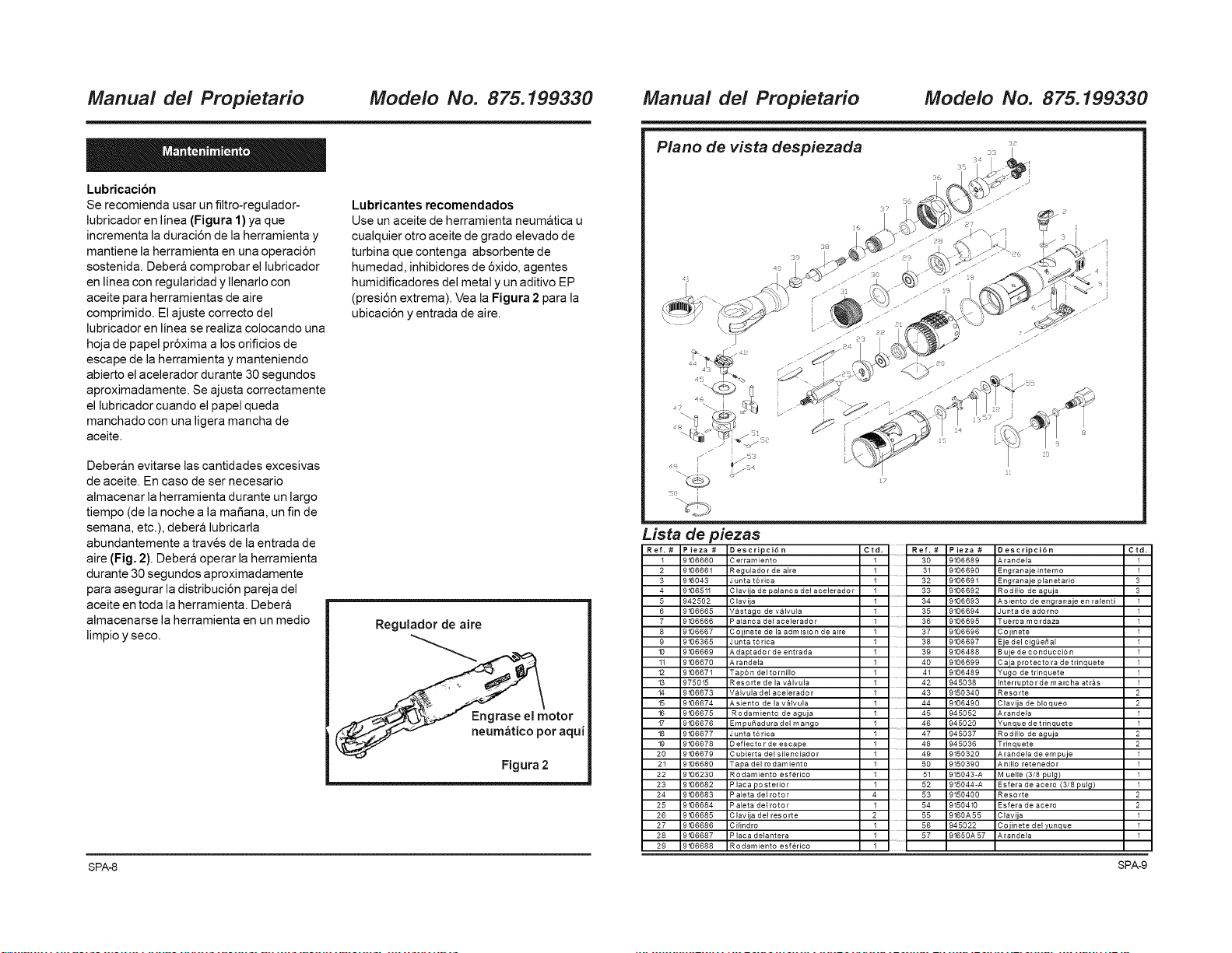
Lubricacion
Se recomienda usar un filtro-regulador-
lubricador en linea (Figura 1) ya que
incrementa la duraci6n de la herramienta y
mantiene la herramienta en una operaci6n
sostenida. Deber& comprobar el lubricador
en linea con regularidad yIlenarlo con
aceite para herramientas de aire
comprimido. El ajuste correcto del
lubricador en linea se realiza colocando una
hoja de papel pr6xima a los orificios de
escape de la herramienta y manteniendo
abierto el acelerador durante 30 segundos
aproximadamente. Se ajusta correctamente
el lubricador cuando el papel queda
manchado con una ligera mancha de
aceite.
Deberan evitarse las cantidades excesivas
de aceite. En caso de ser necesario
almacenar la herramienta durante un largo
tiempo (de la noche a la mafiana, un fin de
semana, etc.), debera lubricarla
abundantemente a traves de la entrada de
aire (Fig. 2). Debera operar la herramienta
durante 30 segundos aproximadamente
para asegurar la distribuci6n pareja del
aceite en toda la herramienta. Debera
almacenarse la herramienta en un medio
limpio y seco.
Lubricantes recomendados
Use un aceite de herramienta neumatica u
cualquier otro aceite de grado elevado de
turbina que contenga absorbente de
humedad, inhibidores de 6xido, agentes
humidificadores del metal y un aditivo EP
(presi6n extrema). Vea la Figura 2 para la
ubicaci6n y entrada de aire.
Regulador de aire
Figura 2
Piano de vista despiezada
[fJ
I
I
Lista de piezas
Ref.# Pieza # Descripci6n Ctd. Ref.# Pieza # Descripci6n Ctd.
1 9106660 C erramiento 1 39 9106689 Arandela 1
2 9106661 Regulado r de aire 1 31 9106690 Engranaje interno 1
3 916943 Junta t6rica 1 32 9106691 Engranaje planet ario 3
4 9106511 C lavija de palanca del acelerado r 1 33 9106692 Rodillo de aguja 3
5 942502 Clavija 1 34 9106693 A siento de engranaje en ralenti 1
6 9106665 Vastago de valvula 1 35 9106694 Junta de adorno 1
7 9106666 P alanca del acelerado r 1
8 9106667 Cojinete de la admisi6 n de aire 1
9 9106365 Junta torica 1
10 9106669 Adaptado r de entrada
1t 9106679 A randela
12 9106671 Tap6 n del to rnillo
13 975015 Reso rte de la valvula
14 9106673 Valvula del acelerado r
15 9106674 Asiento de la valvula
16 9106675 Rodamiento de aguja
17 9106676 Empu_adura del mango
18 9106677 Junta torica
1) 9106678 D efiecto r de escape
29 9106679 C ubierta del silenciado r
21 9106689 Tapa del ro damiento
22 9106239 Ro damiento esferico
23 9106682 Placa posterior
24 9106683 P aleta del rotor
25 9106684 P aleta del rotor
26 9106685 Clavija del reso rte
27 9106686 Cilindro
28 9106687 P laca delant era
29 9106688 Ro damiento esferico
36 9106695 Tuerca mo rdaza 1
37 9106696 Cojinete 1
38 9106697 Eje del cigQe5 al 1
1 39 9106488 B uje de co nducci6 n 1
1 .... 40 9106699 C aia pro tecto ra de t rinquete 1
1 41 9106489 Yugo de trinquete 1
1 42 945038 Interrupto rde m archa atras 1
1 43 9159349 Resorte 2
1 44 9106490 Clavija de bloqueo 2
1 45 945052 Arandela 1
1 46 945020 Yunque de t rinquete 1
47 945037 Rodillo de aguja 2
48 945036 Trinquete 2
1 49 9159329 Arandela de em puje 1
1 50 9150390 A nillo retenedo r 1
51 915943-A M uelle (3/8 pulg) 1
52 915044-A Esfera de acero (3/8 pulg) 1
4 53 9150499 Resorte 2
1 54 9150410 Esfera de acero 2
2 55 9160A55 Clavija 1
1 56 945022 Cojinete del yunque 1
1 57 91659A 57 Arandela 1
1
SPA4 SPA-9
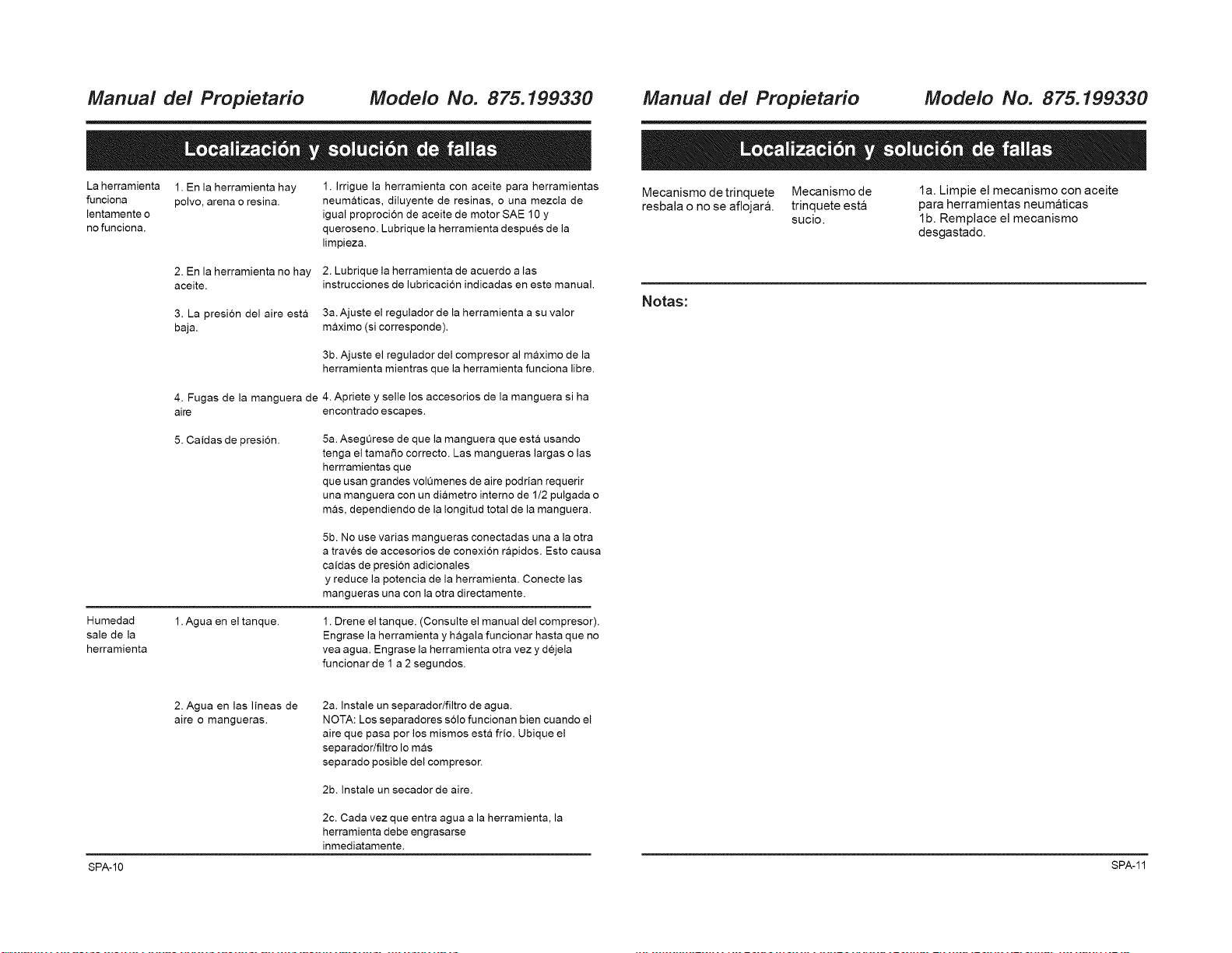
Manual del Propietario Modelo No. 875.199330 Manual del Propietario Modelo No. 875.199330
La herramienta 1. En la herramienta hay
funciona polvo, arena o resin&
lentamente o
no funciona.
1. Irrigue la herramienta con aceite para herramientas
neumaticas, diluyente de resinas, o una mezcla de
igual proproci6n de aceite de motor SAE 10 y
queroseno. Lubrique la herramienta despues de la
limpieza.
2. En la herramienta no hay 2. Lubrique la herramienta de acuerdo a las
aceite, instrucciones de lubricaci6n indicadas en este manual.
3. La presi6n del aire esta
baja.
3a.Ajuste el regulador de la herramienta a su valor
maximo (si corresponde).
3b. Ajuste el regulador del compresor al maximo de la
herramienta mientras que la herramienta funciona libre.
4. Fugas de la manguera de 4. Apriete y selle los accesorios de la manguera si ha
aire encontrado escapes.
5. Caidas de presi6n.
5a. Asegurese de que la manguera que esta usando
tenga el tama_o correcto. Las mangueras largas o las
herrramientas que
que usan grandes volumenes de aire podrian requerir
una manguera con un diametro interne de 1/2 pulgada o
mas, dependiendo de la Iongitud total de la manguera.
Humedad
sale de la
herramienta
5b. No use varias mangueras conectadas una a la otra
a traves de accesorios de conexi6n rapidos. Esto causa
caidas de presion adicionales
y reduce la potencia de la herramienta. Conecte las
mangueras una con la otra directamente.
1. Agua en el tanque. 1. Drene el tanque. (Consulte el manual del compresor).
Engrase la herramienta y hagala funcionar hasta que no
vea agua. Engrase la herramienta otra vez y dejela
funcionar de 1 a 2 segundos.
2. Agua en las lineas de
aire o mangueras.
2a. Instale un separador/filtro de agua.
NOTA: Los separadores s61ofuncionan bien cuando el
aire que pasa por los mismos esta frio. Ubique el
separador/filtro Io mas
separado posible del compresor.
2b. Instale un secador de aire.
2c. Cada vez que entra agua a la herramienta, la
herramienta debe engrasarse
inmediatamente.
Mecanismo de trinquete
resbala o no se aflojar&
Mecanismo de
trinquete esta
sucio.
la. Limpie el mecanismo con aceite
para herramientas neumaticas
lb. Remplace el mecanismo
desgastado.
Notas:
SPA-10 SPA-11

Your Home
For repair - in your home - of all major brand appliances,
lawn and garden equipment, or heating and cooling systems,
no matter who made it, no matter who sold it!
For the replacement parts, accessories and
owner's manuals that you need to do-it-yourself.
For Sears professional installation of home appliances
and items like garage door openers and water heaters.
1-800-4-MY-HOME ® (1-800-469-4663)
Call anytime, day ornight (U.S.A. and Canada)
www.sears,com www.sears.ca
For expert home solutions advice: www.managemyhome.com
Our Home
For repair of carry-in items like vacuums, lawn equipment,
and electronics, call or go on-line for the location of your nearest
Sears Parts & Repair Service Center
1-800-488-1222 (U.S.A.) 1-800-469-4663 (Canada)
Call anytime, day or night
www.sears.com www.sears.ca
To purchase a protection agreement on a product serviced by Sears:
1-800-827-6655 (U.S.A.) 1-800-361-6665 (Canada)
Para pedir servicio de reparaci6n Au Canada pour service en frangais:
a domicilio, y para ordenar piezas: 1-800-LE-FOYER M°
1-888-SU-HOGAR ® (1-800-533-6937)
(1-888-784-6427) www.sears.ca
Sesit
® Registered Trademark / i_ Trademark / s_ Se_[ce Mark of Seats Brands, LLC
® Marca Reg strada / TM Marca de F_bfica / SM Marca de Servic[o de Sears Brands, LLC
w Marque de commerce / _ Marque d_pos_e de Sears Brands, LLC © Sears Brands, LLC