Installation Manual
VRF AIR-CONDITIONER
(HEAT RECOVERY)
IMPORTANT:
THANK YOU FOR PURCHASING THIS CENTRAL AIR
CONDITIONERS. READ AND UNDERSTAND THIS
MANUAL BEFORE USING TH AIR CONDITIONERS.
KEEP THIS MANUAL FOR FUTURE REFERENCE.
Outdoor Unit
Basic Units:
CHV6-072URB
CHV6-096URB
CHV6-120URB
CHV6-144URB
CHV6-168URB
CHV6-192URB
Combination
Modules:
CHV6-216~456URB

Dear user:
Thank you for choosing and using our products. For your better understanding and use of this product, be sure to read
and comply with the following related matters before use
This manual should be considered as a permanent part of the air conditioning equipment and should remain with
the air conditioning equipment.
This manual gives a common description and information for this air conditioner which you operate as well for other
models. pursues a policy of continuing improvement in design and performance of products.The right is
therefore reserved to vary specifications without notice.
cannot anticipate every possible circumstance that might involve a potentia
l hazard. This air conditioner is
designed for standard air conditioning only. Do not use this heat recovery air conditioner for other purposes such as
drying clothes, refrigerating foods or for any other cooling or heating process. Do not install the unit in the following
places. It may cause a fire, deformation, corrosion or failure.
*
Places where oil (including machinery oil) sprays
*
●
●
●
●
●
●
Temperature
●
CAUTION
●
DANGER
WARNING
NOTE
: DANGER indicates a hazardous situation which, if not avoided, will result in death or serious injury.
:WARNING indicates a hazardous situation which, if not avoided, could result in death or serious injury.
:CAUTION, used with the safety alert symbol, indicates a hazardous situation which, if not avoided,
could result in minor or moderate injury.
:NOTE is useful information for operation and/or maintenance.
regions,or places with high acidity or alkalinity.
Do not install the unit in the place where silicon gas drifts. If the silicon gas attaches to the surface of heat exchanger, the fin
surface repels water. As a result, drain water splashes outside of the drain pan and splashed water runs inside of electrical
box. In the end, water leakage or electrical devices failure may occur.
Do not install the unit in the place where the breeze directly catches the animals and plants. It could adversely affect the
animals and plants.
Installation and service engineering must comply with local standards, laws and regulations.
As the“public inaccessible appliances”, the indoor units are required to be installed at a height of no lower than 8.2ft.(2.5m).
The installation of the air conditioner can only be carried out by dealer or professional, and self installation by user may
cause water leakage, electric shock or a fire.
●
If you have any questions, contact your dealer or designated service center of .
●
To protect the environment, please do not discard the product at will, and can provide recycling services in
accordance with the relevant provisions of the country and provide replaceable parts in accordance with national standard
requirements.
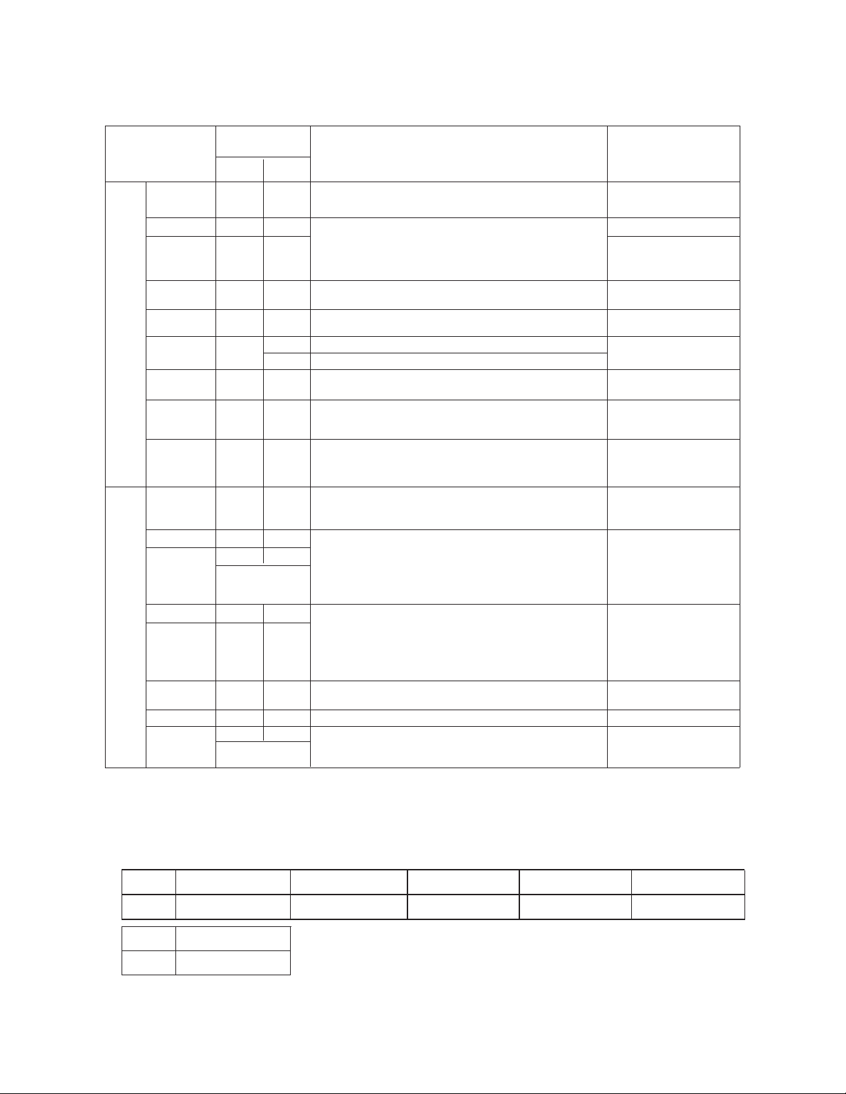
This air conditioner has been designed for the following temperatures. Operate the air conditioner within this range.
●
I
*
Places where a lot of sulfide gas drifts suc
h as a hot spring.
*
Places where flammable gas may g
enerate or flow.
Places where strong salty wind blows such as coast
IMPORTANT NOTICE
Signal words (R, RI and CUTI) are used to identify levels of hazard seriousness.
Definitions for identifying hazard levels are provided below with their respective signal words:
Indoor
Outdoor
Indoor
Outdoor
Cooling
Operation
Heating
Operation
Maximum
Minimum
DX Indoor Unit
89/73
(32/23)
69/59
(21/15)
126
(52)*
14
(-10)
80
(27)
59
(15)
6
(16.5)
-13
(-25)**
o
F DB/
o
F WB
(
o
C DB/
o
C WB)
o
F DB
(
o
C DB)
o
F DB
(
o
C DB)
o
F WB
(
o
C WB)
o
F(
o
C)
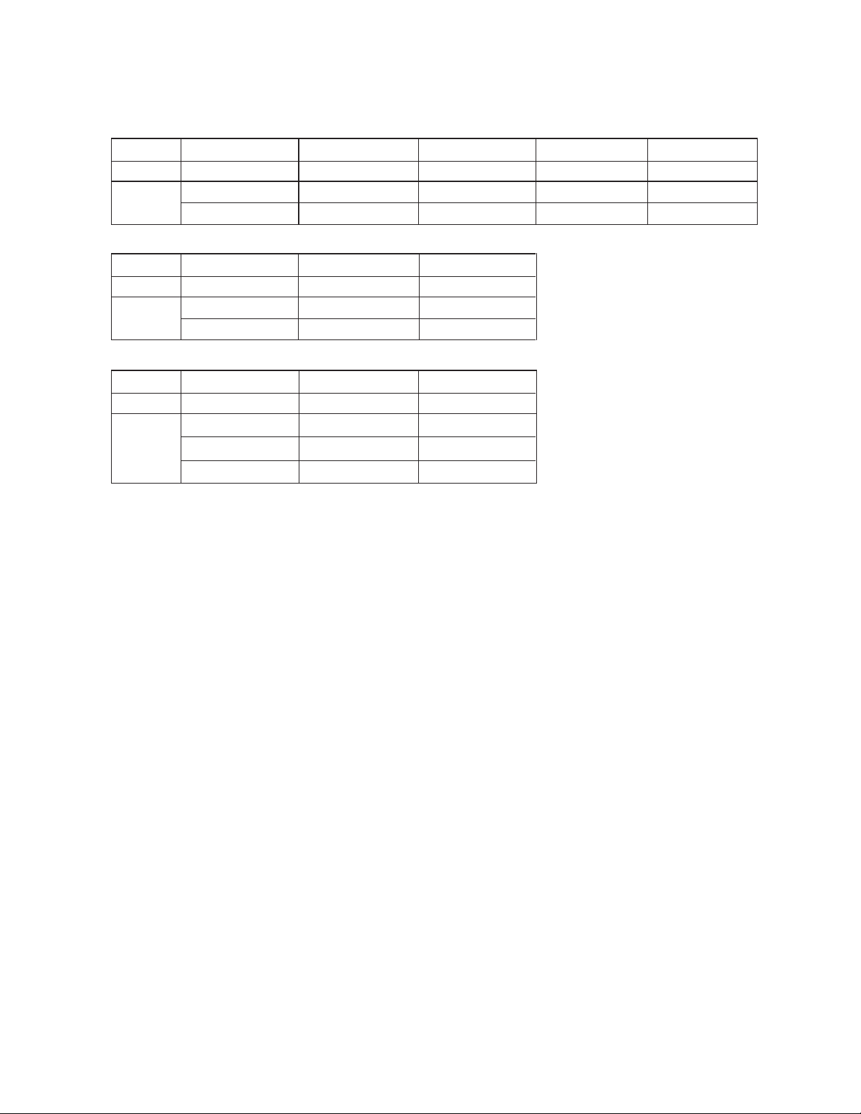
Water Inlet
Outdoor
Water Inlet
Cooling
Operation
Heating
Operation
Maximum
Minimum
Water Module
Outdoor
77
(25)
50
(10)
130
(54)
50
(10)
()
50
(10)
-13
(-25)
**
110
(43)
o
F
(
o
C)
o
F DB
(
o
C DB)
o
F
(
o
C)
NOTES:
(*) 118
o
F(48
o
C )DB ~ 126
o
F(52
o
C) DB, Operation Control Range
(**) -4
o
F(-20
o
C) WB ~-13
o
F (-25
o
C) WB, Operation Control Range
DB:Dry Bulb, WB:Wet Bulb
o
F WB
(
o
C
B)

●
●
●
●
●
●
●
●
●
●
●
●
Do not use any sprays such as insecticide, lacquer, hair spray or other flammable gases within approximatel
y 3.28ft.(1m) from
the system.
If circuit breaker is often activated, stop the system and contact your dealer or service contractor.
Check that the ground wire is securely connected. If the unit is not correctly grounded, it leads electric shock. Do not connect
the ground wiring to gas piping, water piping, lighting conductor or ground wiring for telephone.
Before performing any brazing work, check to ensure that there is no flammable material around. When charging refrigerant be
sure to wear leather gloves to prevent cold injuries.
Protect the wires, electrical parts, etc. from rats or other small animals. If not protected, rats may gnaw at unprotected parts
and which may lead to a fire.
Fix the cables securely. External forces on the terminals could lead to a fire.
Provide a sufficiently strong foundation. If not, the unit may fall down and it may lead to injuries.
Perform electrical work according to Installation Manual and all the relevant regulation and standards.
If the instructions are not followed, an electrical failure and fire may occur due to insufficient capacity and inadequate
performance. Use specified cables between units and choose the cables correctly. If not, an electrical failure or a fire may
break out.
Ensure that the outdoor unit is not covered with ice and snow before use.
●
DANGER
Do not perform installation work, refrigerant piping work, drain pump, drain piping and electrical wiring connection without
referring to our installation manual. If the instructions are not followed, it may result in a water leakage, electric shock or a fire.
In case of a fire, cut off the power immediately; do not touch the electrical parts by hand to avoid electric shock hazard. These
products are equipped with electrical parts. Do not pour water into the indoor or outdoor unit. Otherwise, it will cause a serious
electrical failures.
Do not open the service cover of the indoor or outdoor units without turning OFF the main power supply, otherwise it may
cause a serious safety accident. (In any case, users of the equipment are not allowed to open the service cover).
Do not touch or adjust safety devices inside the indoor unit or outdoor units. If these devices are touched or readjusted, it
may cause a serious accident.
Refrigerant R410A for this unit is incombustible, non-toxic and odorless; however if the refrigerant is leaked and is contacted
with fire, toxic gas will generate. Also because the R410A is heavier than air, the floor surface will be filled with it, which could
cause difficulty with breathing due to insufficient air. Turn OFF the main switch, extinguish any naked flames and contact your
service contractor, if refrigerant leakage occurs. Do not charge oxygen, acetylene or other flammable and poisonous gases
into the refrigerant cycle when performing a leakage test or an air-tight test. These types of gases can cause an explosion. It
is recommended that nitrogen be used for these types of tests.
Refrigerant safety leakage standards for construction and operation systems are determined in accordance with local
regulations or standards.
Use an ELB (Earth Leakage Breaker, with an actuation time of 0.1 second or less) at or above medium induction speed,
otherwise it may cause an electric shock or a fire.
For installation, firmly connect the refrigerant pipe before the compressor starts operating.
For maintenance, relocation and disposal, remove the refrigerant pipe after the compressor stops.
Do not perform a short-circuit of the protection device such as a pressure switch when operating. It may cause a fire and
explosion.
II
WARNING
● Do not step on or put any objects on the product.
● Do not put any foreign matters on the unit or inside the unit.
●
Do not install the indoor unit, outdoor unit, remote control switch and cable within approximately 9.8ft.(3m) from strong
electromagnetic wave radiators such as medical equipment.
● Starting the unit after longtime idleness requires the compressor temperature to meet the starting requirements or reach
a certain heating time.
CAUTION
This appliance can be used by children aged from 8 years and above and persons with reduced physical, sensory or mental
capabilities or lack of experience and knowledge if they have been given supervision or instruction concerning use of the
appliance in a safe way and understand the hazards involved. Children shall not be made by children without supervision.
The A-weighted emission sound pressure level at workstations does not exceed 70 dB(A).
Cancer and reproductive harm-www.P65Warnings.ca.gov.
Take measures to ensure that the refrigerant limitations in ASHRAE Standard 15 (Canada: B52) or other local codes, are
followed. If refrigerant gas has leaked during the installation work, ventilate the room immediately.
●
●
●
●
●
●
●
●
●
●

CHECKING PRODUCT RECEIVED
●
●
Upon receiving this product, inspect it for any shipping damage.
Claims for damage in a written form, either apparent or concealed, should be filed immediately with the shipping
company.
Check the model number, electrical characteristics (power supply, voltage and frequency) and accessories to
determine if they are correct. The standard utilization of the unit shall be explained in these instructions.
Please contact your local agent, as the occasion arises.
’s liability shall not cover defects arising from the alteration performed by a customer without
’s consent in a written form.
I
The heating capacity of the outdoor is decreased according to the air temperature. Therefore, it is recommended
that auxiliary equipment be used in the field when the unit is installed in a low temperature region.
The repair and maintenance of this air conditioner can only be carried out by the professionals.
N OTE:
*
*
●
●
It is recommended to ventilate the room every 3 to 4 hours.
● In some cases, the air conditioner may not operate properly under the following cases.
●
In case the power supplied by the power transformer is less than or equal to the electric power of the air conditioner.
In case the large power-consuming equipment is too close to the power supply wiring for the air conditioner, so that
surge voltage may be inducted in the power supply wiring of the air conditioner.

1.
Structure .................................................................................... .........................................................................................
1.1 Outdoor Unit & Refrigerant Cycle
.................................................................................................................................
TABLE OF CONTENTS
2.
Before Installation ................................................................................................................................................
1.2 Necessary Tools and Instrument List for Installation
...................................................................................................
V
3.
Transportation and Handling ................................................................................................................................
3.1 Transportation
...............................................................................................................................................................
3.2 Handling Method
...........................................................................................................................................................
4.
Outdoor Unit Installation ......................................................................................................................................
4.1 Accessories Factory-Supplied
......................................................................................................................................
4.2 Installation environment
..............................................................................................................................................
4.3 Foundation
...................................................................................................................................................................
4.4 Drainage
.......................................................................................................................................................................
5.Refrigerant Piping Work .......................................................................................................................................
5.1 Piping Materials
...........................................................................................................................................................
5.2 Flaring and Joint
..........................................................................................................................................................
5.3 Caution about Outdoor Unit Installation
.......................................................................................................................
5.4 Piping Connection for System
......................................................................................................................................
6.Electrical Wiring ..................................................................................................................................................
6.1 General Check
.............................................................................................................................................................
6.2 Electrical Wiring
...........................................................................................................................................................
6.3 Electrical Wiring Connection
........................................................................................................................................
6.5 DIP Switch Setting of Outdoor Unit
.............................................................................................................................
7.Additional Refrigerant Charge .............................................................................................................................
7.1 Air-Tight Test
...............................................................................................................................................................
7.2 Vacuuming
...................................................................................................................................................................
7.3 Charging Operation ......................................................................................................................................................
8.Test Run .............................................................................................................................................................
8.1 Before Test Run
...........................................................................................................................................................
8.2 Test Run
.......................................................................................................................................................................
6. Electrical Wiring Connection of The System
...............................................................................................................
1
1
1
2
4
4
5
6
6
6
7
8
11
11
12
13
15
19
19
20
21
22
25
28
28
29
30
3
3
3

1 6
2
7
12
17
3
8
13
18
4
9
14 19
5
1.Structure
1.1 Outdoor Unit & Refrigerant Cycle
Regarding structure drawings and refrigerant cycle diagram, please refer to Technical Catalogue.
No.
Tool
No.
Tool
No.
Tool
Handsaw
Phillips Screwdriver
No.
Vacuum Pump
Refrigerant Gas Hose
Megohmmeter
Copper Pipe Bender
Plier
Pipe Cutter
Brazing Kit
Hexagon Wrench
Spanner
Charging Cylinder
Control Valve
Cutter for Wires
Gas Leak Detector
Leveller
Clamper for Solderless
Terminals
Hoist (for Indoor Unit)
Ammeter
Voltage Meter
Note: Use tools and measuring instruments exclusively for the new refrigerant R410A in case of direct
contact with the refrigerant.
The design pressure for this product is 601psi(4.15MPa).
To avoid accidental mixing of the different refrigerant or different refrigerant oil, the sizes of the charging
connections have been changed. It is necessary to prepare the foll
owing tools before performing installation.
Tool
The pressure of refrigerant R410A is 1.4 times higher than that of conventional refrigerant, impurities such as
moisture, oxide film, and grease affect R410A easily. Be sure to remove any moisture, dust, different refrigerant
or refrigeration oil from the refrigerant cycle. Otherwise, it may lead to explosion, injury, leakage, electric shock
or a fire.
10
11
15
16
20
1
1.2 Necessary Tools and Instrument List for Installation
DANGER
2
Capacity
kBtu/h(RT)
96(8RT)
120(10RT)
144(12RT)
168(14RT)
Model
192(16RT)
CHV6-072URB
CHV6-096URB CHV6-120URB
CHV6-144URB
CHV6-168URB
CHV6-192URB
(6RT)
Measuring Instrument
and Tool
R407C
R410A
Reason of Non-Interchangeability
and Attention (★
: Strictly Required)
Application
Pipe Cutter
Chamfering
Reamer
○
——
Cutting Pipe
Removing Burrs
Flaring Tool
○ ○■
Flaring for Tubes
Extrusion -
Adjustment
Gauge
■
*
R410A requires high pressure resistance piping and larger
flaring. In case of material 1/2H, flaring is not
available.(The flaring tools for R410A are applicable to
R407C)
Dimensional Control
of Tube after Flaring
Pipe Bender
○ ○
*
In case of material 1/2H, bending is not available. Use elbow
for bend and braze.
Bending
Expanding
Tool
○ ○
*
In case of material 1/2H, expanding of tube is not available.
Use joint for connecting tube.
Expanding Tubes
Torque
Wrench
*
For Φ1/2in., Φ5/8in. of R410A, spanner size is up to 5/64in.
Connection of Flare Nut
Brazing Tool
○ ○
*
Perform brazing work properly (adjustable flame and heating
method, filler applicable)
Nitrogen Gas
○
*
Strict control against contamination (Blow nitrogen during
brazing.)
Prevention from Oxidation
during Brazing Air-tight test
Refrige-
rant
Pipe
Lubrication Oil
(for Flare
Surface)
■
* Use a synthetic oil which is equivalent to the oil used in the
refrigerant cycle.
* Synthetic oil absorbs moisture quickly.
Applying Oil to the Flared
Surface
Refrigerant
Cylinder
●
■
*
Check the cylinder for the corresponding refrigerant.
★Liquid refrigerant charging is required regarding zeotropic
refrigerant.
Refrigerant Charging
Vacuum Pump
○
★The current pumps are applicable. However, it is required to
mount a vacuum pump adapter which can
prevent reverse flow
when a vacuum pump stops, resulting in no reverse oil flow.
Vacuum Pumping
Vacuum Pumping, Vacuum
Holding, Refrigerant Charg-
ing and Check of Pressures
Control Valve
● ■
Charging
Hose
● ■
Charging
Cylinder
×
*
Use the weight scale when charging
Refrigerant Charging
Weight Scale
○ ○
——
Measure refrigerant quantity
●
※■
Adapter for
Vacuum
Pump Reverse
Flow prevention
Refrige-
rant
Charge
Vacuum
Drying
Interchangeable
with R410A
*
The current gas leakage detector (R22) is not applicable due
to different detecting method.
Refrigerant Charging Gas
Leakage Check
■
For Φ1/4in.,Φ3/8.、Φ3/4in., spanner size is the same.
○
*
No interchangeability is available due to higher pressures
when compared with R22. Connection diameter is different:
R410A: UNFl/2, R407C: UNF7/16
★Do not use old ones to the different refrigerant. Otherwise,
mineral oil will flow into the cycle and cause sludges, resulting
in clogging or compressor failure.
※ interchangeable with R407C
●
※■
Interchangeable
with R410A
*
■: only for Refrigerant R410A (not interchangeable with R22)
○ : interchangeable with current R22
× : Prohibited
● : only for Refrigerant R407C (not interchangeable with R22)
○
○
○
●
○
Brazing for Tubes
Refrigerant
Gas Leakage
Detector
Interchangeability
with
R22
2.Before Installation
Line-Up of Outdoor Unit
【Basic Unit】
Capacity
kBtu/h(RT)
Model
×
-
【Combination Module】
※
3
Combination
Capacity
kBtu/h(RT)
Model
Combination
Capacity
kBtu/h(RT)
Model
Combination
Capacity
kBtu/h(RT)
Model
456(38RT)
CHV6-456URB
CHV6-168URB
CHV6-144URB
CHV6-144URB
432(36RT)
CHV6-432URB
CHV6-144URB
CHV6-144URB
CHV6-144URB
408(34RT)
CHV6-408URB
CHV6-144URB
CHV6-144URB
384(32RT)
CHV6-384URB
CHV6-192URB
CHV6-192URB
360(30RT)
CHV6-360URB
CHV6-192URB
CHV6-168URB
336(28RT)
CHV6-336URB
CHV6-168URB
CHV6-168URB
312(26RT)
CHV6-312URB
CHV6-168URB
CHV6-144URB
288(24RT)
CHV6-288URB
CHV6-144URB
CHV6-144URB
264(22RT)
CHV6-264URB
CHV6-144URB
CHV6-120URB
240(20RT)
CHV6-240URB
CHV6-120URB
CHV6-120URB
216(18RT)
CHV6-216URB
CHV6-120URB
CHV6-096URB
CHV6-120URB
3.Transportation and Handling
3.1 Transportation
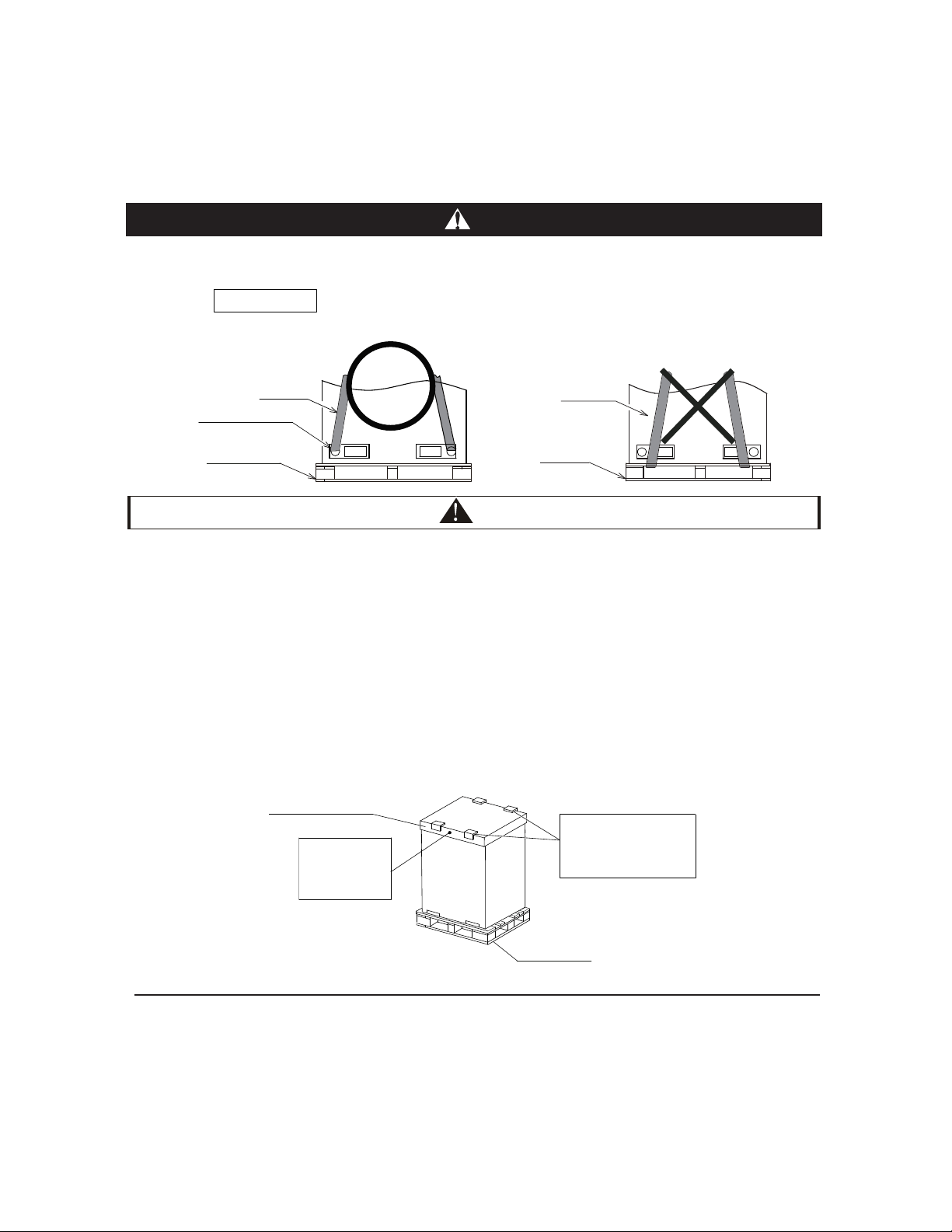
1.Transportation and Storage
Due to the limited strength of corrugated paper frame, pay attention to the followings in order
to prevent the unit from deformation.
● Do not step on or put any objects on the product.
● Apply two lifting wires onto the outdoor unit, when lifting by crane.
● Do not stack the product when storing.
2.Transportation and Wire Rope
● To protect the unit, do not remove any packing.
● Do not stack or put any objects on the product.
● Apply wire ropes on the both side of the unit as shown in the figure.
CAUTION
4
Rope Position
CORRECT
INCORRECT
Transport the product as close to the installation location as practical before unpacking. When using
a crane, hang the unit according to the description on the label attached to the outdoor unit.
Corrugated
Paper Frame
Do not remove
corrugated
paper frame and
plastic bands
Apply ropes on the splints
or corrugated paper with
thickness greater than
19/32in.(15mm).
Wooden Pallet
Do not hang the unit by the ropes at the wooden pallet.
DANGER
Wire Rope
Wooden Pallet
Wire Rope
Apply wire ropes through
circular holes
Wooden Pallet
NOTE
Do not apply
excessive
for
c
e (
both s
ides)
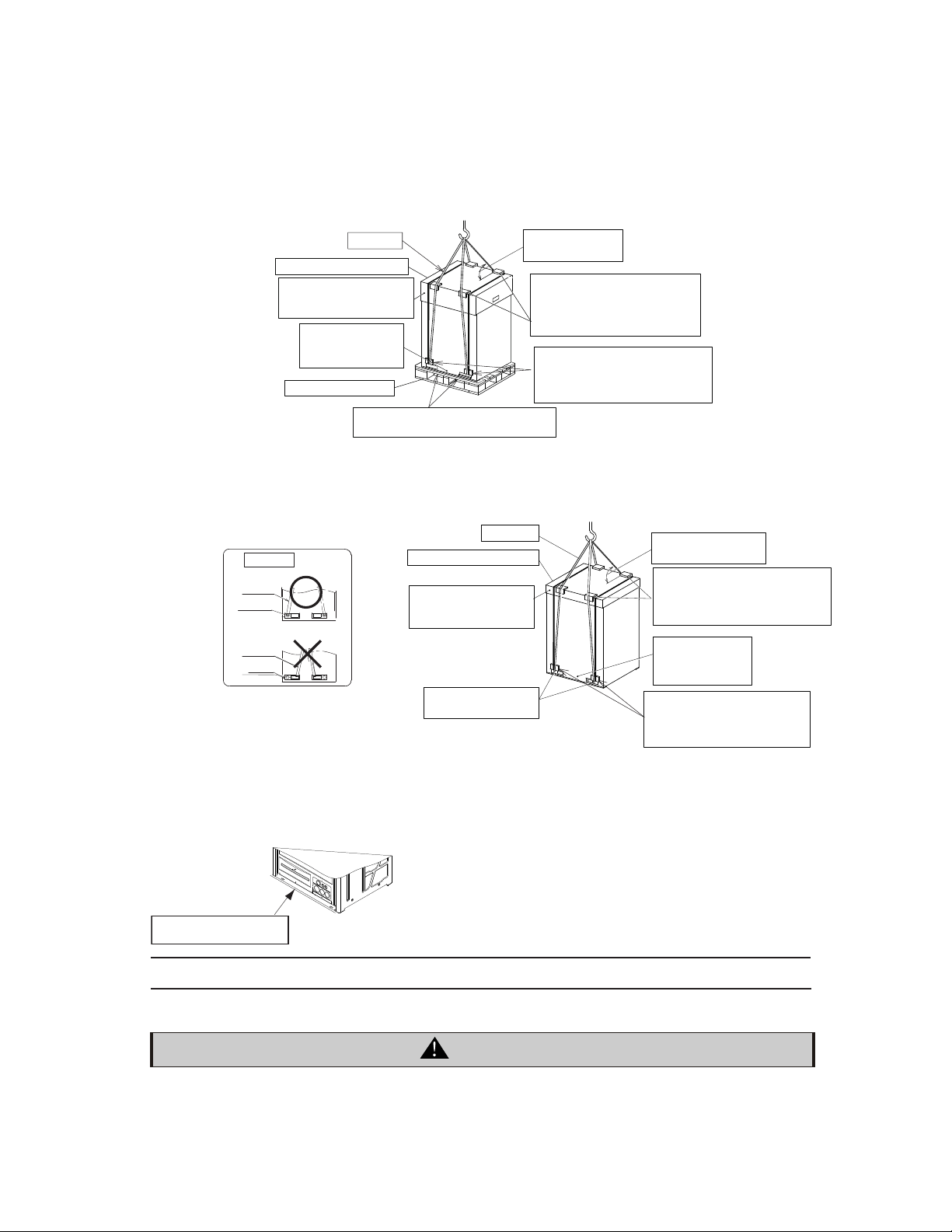
When hanging the unit, ensure a balance of the unit, check to ensure safety and lift up smoothly.
Do not remove any packing materials.
Hang the unit with two wire ropes, as shown in Fig. 3.1.
(3)Hang the unit without wooden pallet, as shown in Fig.3.2.
*Do not push the bottom base by fork.
*Do not use roller.
In case of transportation after unpacking, protect the unit with splints or cloth.
3.2 Hanging Method
WARNING
Check to ensure that no foreign matters left in the outdoor unit before installation and test run.
Otherwise, a fire, failure or personal injury, etc. may occur.
5
Fig. 3.1 Hanging Work for Transportation
CORRECT
Rope Position
Wire Rope
INCORRECT
Wire Rope
Square Hole
Apply wire ropes
through circular holes
Do not remove
corrugated paper frame
and plastic bands
Wire Rope
Corrugated Paper Frame
Apply rope on the splints or
corrugated paper with thickness
greater than 19/32in. (15mm)
Angle of wire rope
greater than 60°
Do not apply any
force
(Both Sides)
Do not apply excessive force the square holes with forks or
other materials. The bottom of the unit may be deformed.
Do not apply
any force .
(Both Sides)
Do not remove
corrugated paper frame
and plastic bands
Corrugated Paper Frame
Wooden Pallet
Wire Rope
Carefully guide the sling belts through
both side slots of the wooden pallet.
Bottom corners: Attach four
5/8in (15mm) thick cardboard
padding on both sides at
this point for protection.
Apply rope on the splints
or corrugated paper with
thickness greater than
19/32in. (15mm).
Angle of wire rope
than 60°
Bottom corners: Attach four
5/8in (15mm) thick cardboard
padding on both sides at
this point for protection.
Circular Hole
Fig. 3.2 Hanging Work without Wooden Pallet
4.Outdoor Unit Installation
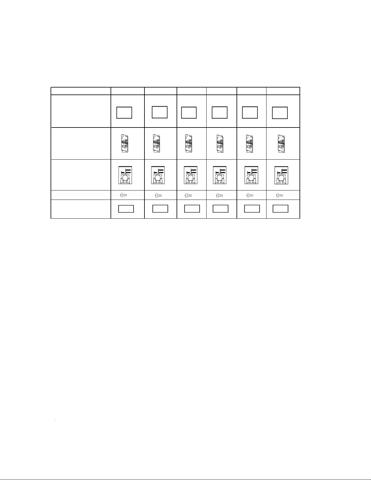
4.1 Factory-Supplied Accessories
Check to ensure that the following accessories are packed with the outdoor unit.
Table 4.1 Factory-Supplied Accessories
6
NOTE:
If any of these accessories are not packed with the unit, please contact your contractor.
NOTES:
4.2 Installation
1.Do not install the outdoor unit where there is a high level of oil mist, flammable gases, salty air or harmful
gases such as sulphur and an acid or alkaline environment.
2.Do not install the outdoor unit where the electromagnetic wave is directly radiated to the electrical control box.
3.Install the outdoor unit as far as possible, at least 9.8ft.(3m) from the electromagnetic wave radiator.
nit:in.(mm)
1.
2.
3.
72 96 120 144 168 192
Accessory
Accessory
pipe pouch
Screw (Spare)
Installation Manual
×3
×3
×3
×3
×3
×3
Electrical
accessory pouch
Fastener pouch
×1
×1
×1
×1
×1
×
1
×
1
×
1
×
1
×
1
×
1
×
1
×
1
×
1
×
1
×
1
×
1
×
1
(1) Install the outdoor unit in a dry well ventilated environment.
(2) Install the outdoor unit where it is in the shade or a place where not be exposed to direct sunshine
or direct radiation from high temperature heat source.
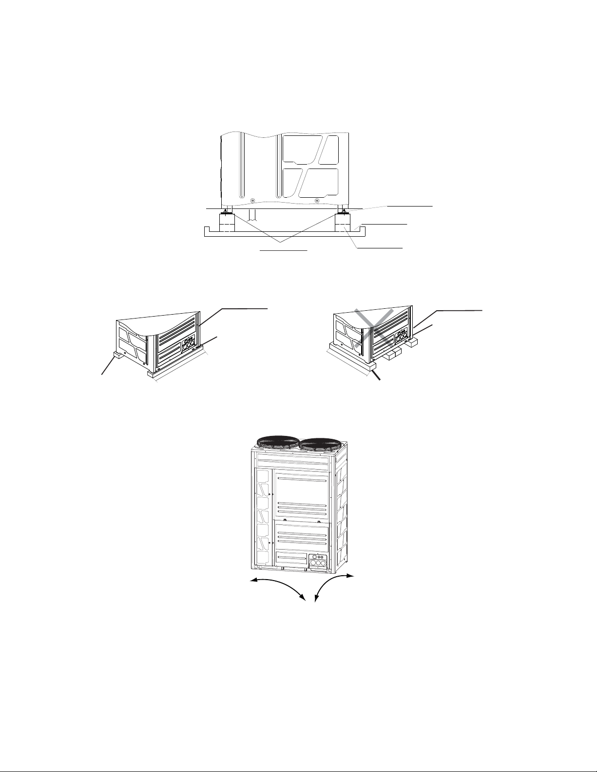
(3) Install the outdoor unit where the sound or the discharge air from the outdoor unit does not affect
neighbors or surrounding ventilation.
The operating sound at the rear or right/left side is 3 to 6dB(A) higher than the value in the catalog at the
front side.
(4) Install the outdoor unit in a space with limited access to general public.
(5) Check to ensure that the foundation is flat, level and sufficiently strong.
(6) Do not install the outdoor unit where dust or other contamination could block the outdoor heat exchanger.
(7) When installing the outdoor unit in snow-covered areas, mount the field-supplied hoods on the top of the
outdoor unit and the inlet side of the heat exchanger.
(8) In heating or defrosting operation, drain water is discharged. Provide adequate drainage around the
foundation. If installing the unit on a roof or a veranda, avoid draining in or over walkways to prevent
water dripping on people or the formation of ice in winter. In case of installing such a place, provide the
additional drainage around the foundation.
(9) Do not install the outdoor unit in a space where a seasonal wind directly blows to the outdoor heat
exchanger or a wind from a building space directly blows to the outdoor fan.
unit:in.(mm)
left and right
front and rear
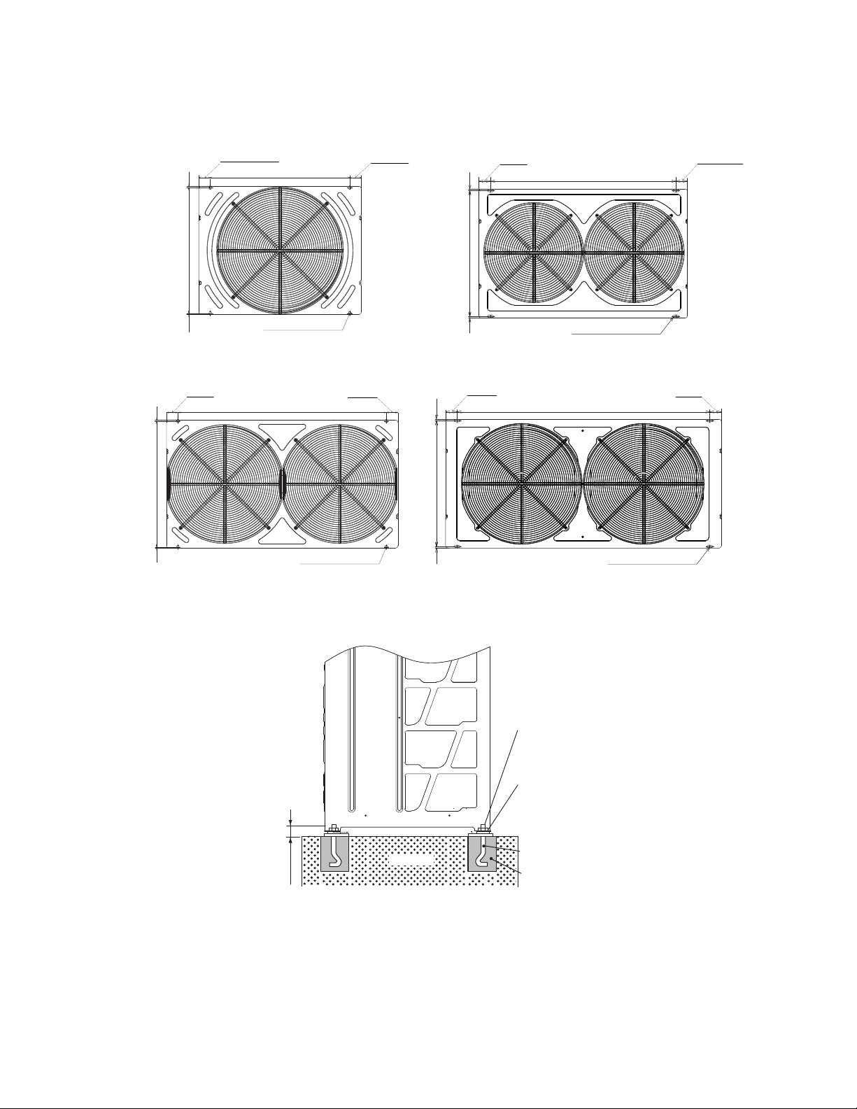
4.3 Foundation
*Provide concrete foundation as shown in the figure.
*Do not provide concrete foundation as shown below.
The foot of the outdoor unit may be deformed.
(3) Install the outdoor unit in the front-rear and right-left direction horizontally with a level gauge. Check to
ensure that the gradient in four directions (front, rear, right and left) is within
24/64in.(10mm).
(4) Provide a strong and correct foundation so that:
a. the outdoor unit is not on an incline.
b. no abnormal sound.
c. the outdoor unit will not fall down due to a strong wind or earthquake.
●Concrete Foundations
(1) The height of the foundation should be 5-29/32in.(150mm ) higher than
the ground level.
(2) Provide a drainage ditch around foundation for smooth drain.
7
Mortar Hole
Φ3-15/16(100)×Depth 5-29/32(150)
Drainage
Width 3-15/16(100)×Depth 25/32(20)
Drainage
Vibration Proof Mat
CORRECT
Front Side of Unit
Foot
Width
Foundation
Foot
Width
Front Side of Unit
INCORRECT
Foundation
2-31/64(63)
2-31/64(63)
24-9/16(624)
Model: 1
44-168
unit: in.(mm)
(5) When installing the outdoor unit, fix the unit by anchor bolts (field-supplied).
Nut
Washer
Anchor Bolt
M12
Filled with Mortar
3-15/16(100)
Mortar
4.4 Drainage
Drainage is discharged during heating and defrosting operation, and so is rain
water. Pay attention to the following:
(1) Choose a place where well drainage is available, or provide a drain ditch.
8
Model: 1
92
unit: in.(mm)
Secure the outdoor unit with the anchor bolts.
2-43/64
(68)
Model:
72-96
unit: in.(mm)
2-43/64
(68)
31-31/32
(812)
2-43/64
(68)
Model:
120
unit: in.(mm)
2-43/64
(68)
42-21/64
(1075)
43/64
(17)
43/64
(17)
28-17/64
(718)
43/64
(17)
43/64
(17)
28-17/64
(718)
Hole of Anchor Bolt
4×25/32(20)×19/32(
15)
Hole of Anchor Bolt
4×25/32(20)×19/32(15)
Hole of Anchor Bolt
4×25/32(20)×19/32(
15)
Hole of Anchor Bolt
4×25/32(20)×19/32(15)
43/64
(17)
43/64
(17)
28-17/64
(718)
57-41/64
(1464)
2-43/64
(68)
2-43/64
(68)
28-17/64
(718)
43/64
(17)
43/64
(17)
47-29/32
(1217)
2-43/64
(68)
2-43/64
(68)
(2)
Do not install the unit over the walkways. Condensate may fall on people.
In case of installing the unit in such a place, provide the additional drain pan.
(3)
When drain piping is necessary for the outdoor unit, use the drain boss set (Optional, DC-01Q).
Do not use drain boss and drain pan kit in the cold area. The drain water in the drain pipe may be frozen
and then crack the drain pipe.
(4) When installing the unit on a roof or a veranda, drain water sometimes turns to ice on a cold morning.
Therefore, avoid draining into an area where people often use because it is slippery.
9
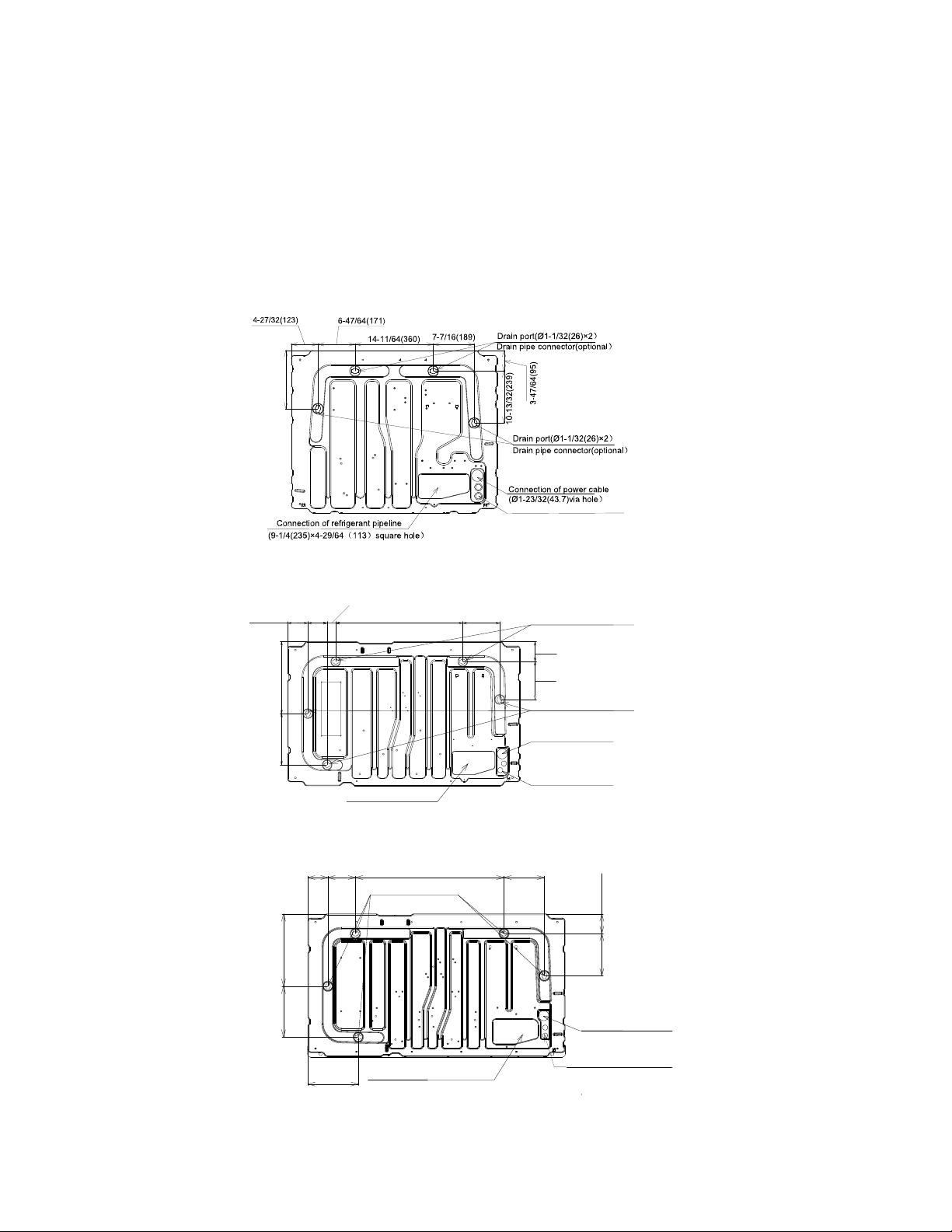
unit: in.(mm)
Model: 72-96
Model: 120
unit: in.(mm)
unit: in.(mm)
(8-21/32(220)×4-23/32(120) square hole)
Model: 144-168
Connection of communication cable
(Ø55/64(22)×2 via hole)
0-3/64(268)
4-9/64(105)
25-63/64(660)
7-9/16(
192
)
Drain port
(Φ1-1/32(26)x 2)
Drain pipe connector (optional)
Drain port (Φ1-1/32(26)×2)
Drain pipe connector (optional)
Connection of power cable
(Φ1-23/32(43.7) via hole)
Connection of communication cable
(Ø
55/64(22)×2 via hole)
Connection of Refrigerant pipeline
14-45/64(373)
10-33/64(267)
4-1/16(103)
1-49/64(45)
3-15/16
(100)
7-3/4(197)
Drain port (Φ1-1/32(26)×5)
Drain pipe connector
(optional)
Connection of power cable
Connection of Refrigerant pipeline
(9-
2
1/4(23
)×-3/64(128) square
hole)
8-11/32(212
)
30-45/64(780)
4-9/64(105)
5-45/64(145
)
10-
7/16(265
)
14-61/64(380)
8-47/64(222)
10-33/64(267)
4-1/16(103)
(Φ1-23/32(43.7) via hole)
Connection of communication cable
(
Ø
5
5/
64
(2
2
)
×2 via hole)
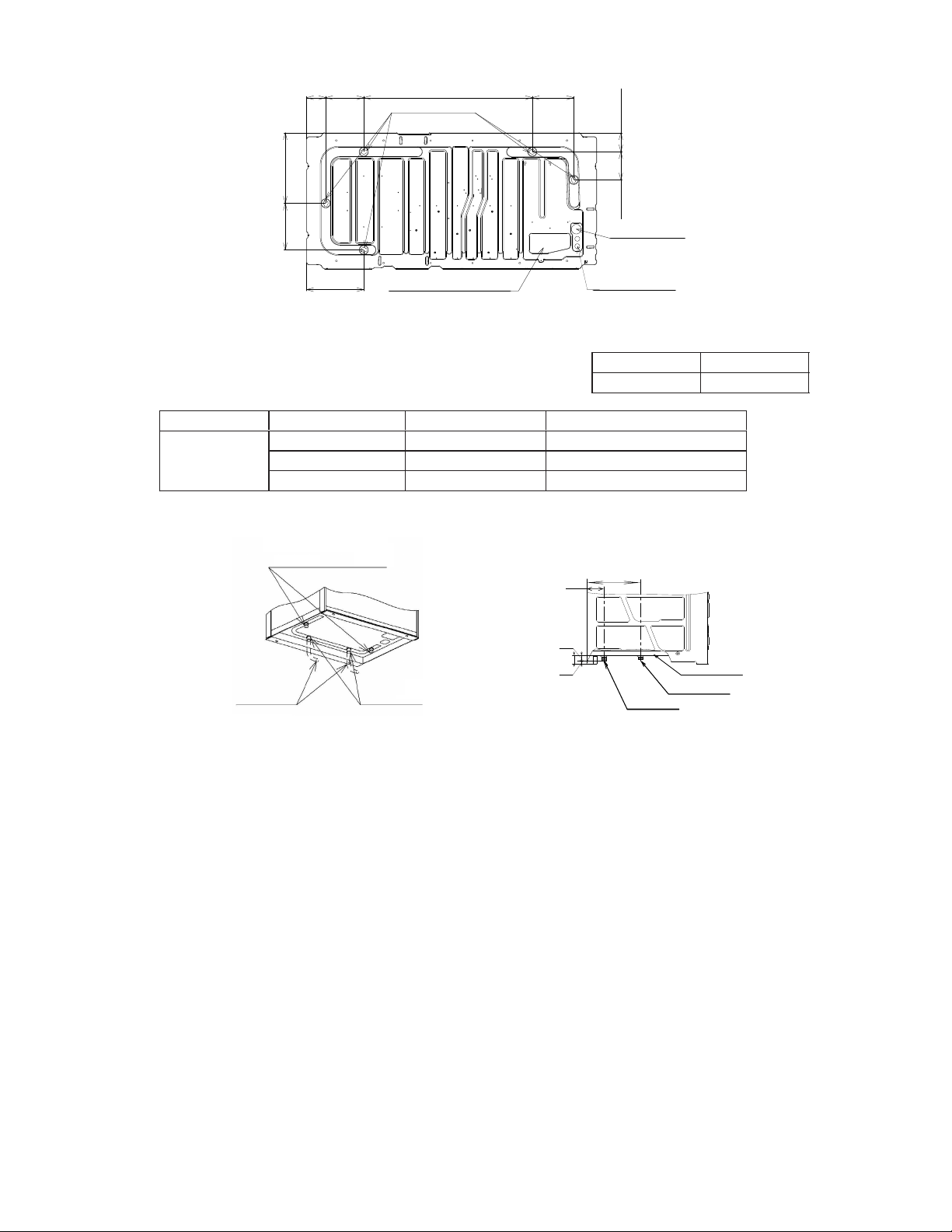
DC-01Q
DC-01Q
1
1
4
Name Model
Drain Boss
Model
Parts Name
Application
Drain Cap
Rubber Cap
Drain Boss
Connecting for Drain Piping
Embolization for Drain Hole
Sealing for Boss and Cap
Installation Position
Example: Model 72
● Drain Boss (Optional Parts)
The drain boss is for the drain pipe connection in order to use
outdoor unit bottom base as a drain pan.
Component Formation of Drain Boss
Q'ty
Drain Cap Position (2 Places)
Drain pipe
(Field-Supplied)
Drain Boss Position (2 Places)
(Outdoor Unit Rear Side)
Side view
(Front Side)
Bottom Base
Drain Cap
Drain Boss
Rear Side
3-47/64(95)
12-61/64(329)
2-3/64(52)
2-23/64(60)
5/16(8)
10
Model: 192
unit: in.(mm)
Drain port (
Φ1-1/32(26)×
5)
Drain pipe connector
(optional)
Connection of power
cable (Φ1-23/32(43.7)
via hole)
Connection of
communication cable
(
Ø
5
5/
64(22)×2 via hole)
Connection of Refrigerant pipeline
(
8-/4(225)×4-
/4(108)
square hole)
8-31/32(228)
36-17/32(928)
4-11/64(10
6
)
8-15/64(209)
12-
13/32(315)
15-5/16(389)
10-1/8(257)
6-1/16(154)
4-11/64(106)
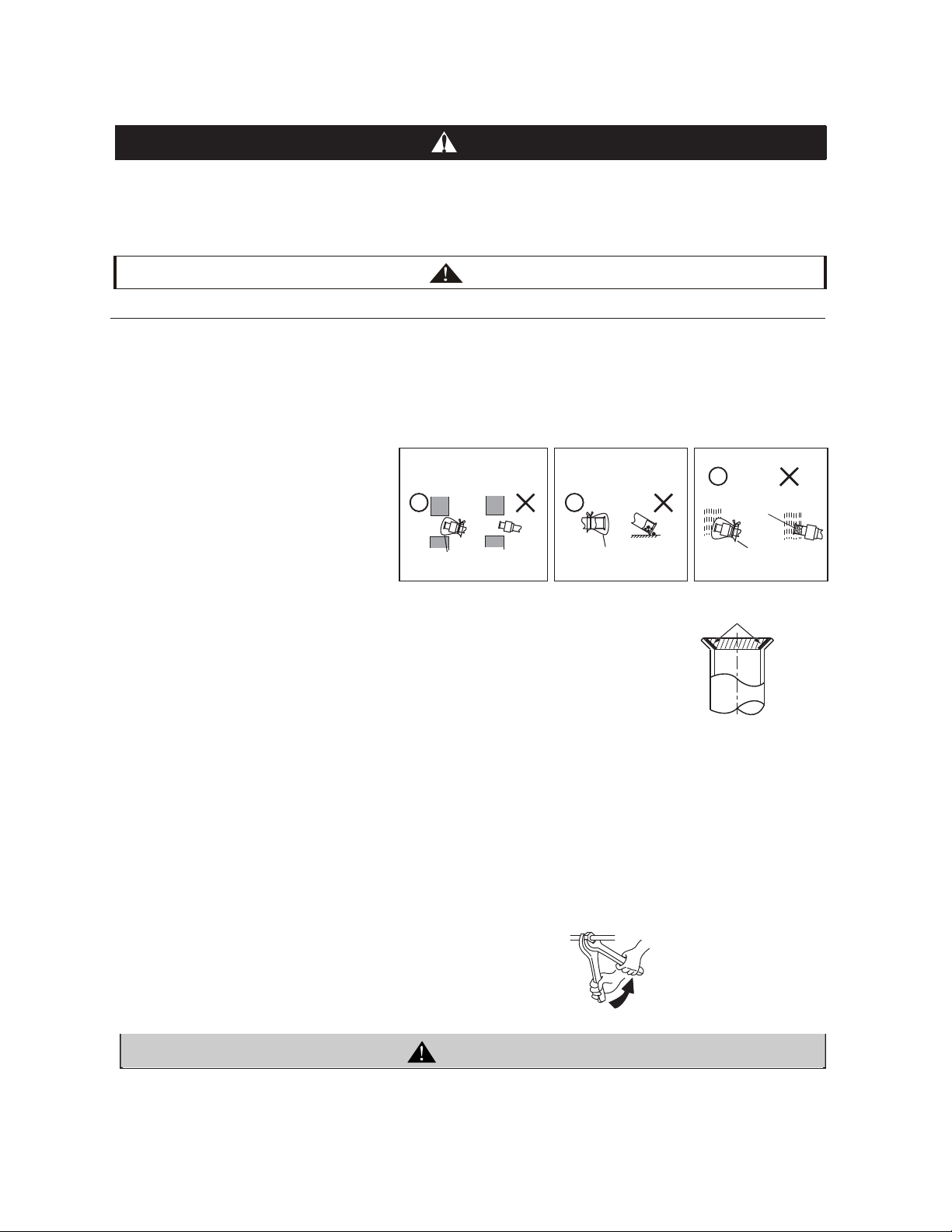
When installing pipe through the wall, secure
a cap at the end of the pipe.
Correct Incorrect
Hole Hole
Attach a cap or vinyl tape.
Do not place the pipe directly on the
ground
Correct Incorrect
Attach a cap or vinyl tape.
Correct
Incorrect
Rain water can enter
Attach a cap or
vinyl bag with
rubber band.
with two
●Use refrigerant R410A in the refrigerant cycle.
Do not charge oxygen, acetylene or other flammable and poisonous gases into the refrigerant cycle when
performing a leakage test or an air-tight test. These types of gases are extremely dangerous and can cause
an explosion. It is recommended that compressed air, nitrogen be used for these types of tests.
●Check to ensure that no pressure exists inside the stop valve before removing the flange
5.Refrigerant Piping Work
5.1 Piping Materials
(1) Prepare copper pipes to be supplied in the locality.
(2) Select the piping size from the Technical Catalog.
(3) Select clean copper pipes. Make sure there is no dust and moisture inside the pipes. Purge pipes with nitrogen
●Cautions for Refrigerant Pipe Ends
●Cautions for Piping Connection Work
(1) Connect the indoor/outdoor units with refrigerant pipes. Fix the pipes and pay attention
(2) Apply refrigerant oil slightly on the sheet surface of the pipe and flare nut before the
NOTE:
Refrigerant oil is field-supplied.
●When tightening the flare nut, use two
.
Apply Refrigerant Oil
DANGER
CAUTION
Ensure to connect the piping among the units in the same refrigerant cycle.
Do not apply excessive force to the flare nut when tightening. Otherwise, the flare nut may crack due to
aged deterioration and refrigerant leakage may occur. Use the specified tightening torque.
11
【Model: FVC68D】
WARNING
or dry air to remove any dust or foreign matters before connecting pipes. Do not use any tools which produce a
lot of swarf such as a saw or a grinder.
not to contact with weak materials such as ceiling. Otherwise, vibration of piping may
give off abnormal sound.
flaring work. Then tighten the flare nut by two spanners with the specified tightening
torque. Perform the flaring work on the liquid piping then on the gas piping. Check
the gas leakage after the flaring work.
(3) In case the temperature and humidity inside the ceiling exceed 80.5°F/RH80%, apply additional insulation
(approx. 3/8in. thickness) to the accessory insulation. It prevents dew condensation on the surface of the
insulation (refrigerant pipe only).
(4) Perform the air-tight test (601psi for the test pressure).
(5) Perform cold insulation work by insulating and taping the flare connection and reducer connection. Also
insulate all the refrigerant pipes.

12
1/64(0.4)~1/32(0.8)R
FA
Fd
90
o
+
2
o
B
Flare Nut
unit:in.(mm)
1/2H material
Thickness Material
1/32(0.8)
O material
1/32(0.8)
1/32(0.8)
3/64(1.0)
3/64(1.0)
3/64(1.0)
3/64(1.0)
3/64(1.0)
3/64(1.1)
3/64(1.35)
1/16(1.45)
1/16(1.55)
5/64(2.0)
5/64(2.0)
Diameter
1/2H material
Φ1/4(6.35)
Φ3/8(9.53)
Φ1/2(12.7)
Φ5/8(15.88)
Φ3/4(19.05)
Φ7/8(22.2)
Φ1(25.4)
Φ1-1/8(28.6)
Φ1-1/4(31.75)
Φ1-1/2(38.1)
Φ1-5/8(41.3)
Φ1-3/4(44.5)
Φ2(50.8)
Φ2-1/8(53.98)
O material
O material
O material
1/2H material
1/2H material
1/2H material
1/2H material
1/2H material
1/2H material
1/2H material
1/2H material
R410A
5.2 Flaring and Joint
Flaring Dimension
Perform the flaring work as shown below.
(*)It is impossible to
perform flaring work with
1/2H material. In this
case, use an accessory
pipe (with a flare)
Joint Selection
If you use 1/2H material, you can not perform flaring work. In this case, use a joint selected from the chart below.
45
o
+
2
o
Piping Thickness and Material
Use the pipe as below.
●
●
●
Diameter (Φd)
R410A
1/4(6.35) 23/64(9.1)
3/8(9.53) 33/64(13.2)
1/2(12.7) 21/32(16.6)
5/8(15.88) 25/32(19.7)
3/4(19.05)
(*)
A
1/64
+0
unit:in.(mm)
<Minimum Thickness of Joint (in.(mm))>
Diameter R410A
Φ1/4(6.35) 1/64(0.5)
Φ3/8(9.53) 1/32(0.6)
Φ1/2(12.7) 1/32(0.7)
Φ5/8(15.88) 1/32(0.8)
Φ3/4(19.05) 1/32(0.8)
Φ7/8(22.2) 1/32(0.9)
Φ1(25.4) 1/32(0.95)
Φ1-1/8(28.6) 3/64(1.0)
Φ1-1/4(31.75) 3/64(1.1)
Φ1-1/2(38.1) 3/64(1.35)
Φ1-5/8(41.3) 1/16(1.45)
Φ1-3/4(44.5) 1/16(1.55)
Φ2(50.8) 5/64(2.0)
Φ2-1/8(53.98) 5/64(2.0)
< Flare Nut Dimension B (in.(mm))>
Diameter
R410A
Φ1/4(6.35) 43/64(17)
Φ3/8(9.53)
55/64(22)
Φ1/2(12.7) 1-1/32(26)
Φ5/8(15.88) 1-9/64(29)
Φ3/4(19.05)
1-27/64(36)
13
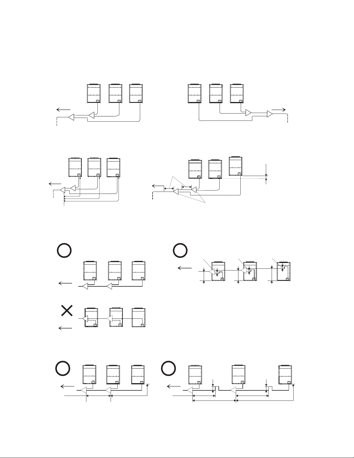
Outdoor Unit Alignment
Taking three-module combination of outdoor unit as an example.
Align the outdoor unit from large capacity as A>B>C, and outdoor Unit "A" should be located at the indoor
unit side.
Piping Work between Outdoor Units
(1) Piping Length between Manifold Pipe (at outdoor unit side) and outdoor unit should be LA<LB<LC<32.8ft.(10m).
LA LB LC
Unit
A
Unit
B
Unit
C
Outdoor
Outdoor
Outdoor
Outdoor
Unit
C
Outdoor
Unit
B
Outdoor
Unit
A
A
B
C
Oil Trap
Min. 7-7/8(200)
11-11/13
(300)
Max.
5.3 Caution about Outdoor Unit Installation
(2)
Taking three-module combination of outdoor unit as an example.
Place the Manifold Pipe lower than the outdoor unit piping connection.
In case that the Manifold Pipe is placed higher than the outdoor unit piping connection, keep a distance of
11-13/16in.(300mm)(max.) between the Manifold Pipe and the bottom of the outdoor unit. Also, provide the oil trap
(Min.7-7/8in.(200mm)) between the Manifold Pipe and the bottom of the outdoor unit.
(3) In case the piping length between the outdoor is 6.6ft.(2m) or more, the oil trap should be provided for the gas pipe so
that the accumulation of the refrigerant may not occur.
Indoor Unit Side
Indoor Unit Side
Indoor Unit Side
Indoor Unit Side
Outdoor
Unit
Outdoor
Unit
Outdoor
Unit
A
Outdoor
Unit
B
Outdoor
Unit
C
Outdoor
Unit
Keep the direct distance
of 19-11/16(500)mm or
more after the Manifold
Pipe
Max. lift difference
between outdoor
units is no more than
3-15/16in.(100mm)
Manifold Pipe
Indoor Unit Side
Oil Trap
Oil Trap
Max.
Max.
Indoor Unit Side
Indoor Unit Side
Indoor Unit Side
Indoor Unit Side
Less than 6.6ft.(2m)
Less than 6.6ft.(2m)
* Less than 6.6ft.(2m)
*6.6ft.(2m) or longer
Oil Trap
Oil Trap
Less than 6.6ft.(2m)
6.6ft.(2m)or longer
Less than 6.6ft.(2m)
6.6ft.(2m) or longer
Outdoor Unit Capacity: A≥B≥C
Outdoor Unit Capacity: A≥B≥C Outdoor Unit Capacity: A≥B≥C
unit: in.(mm)
nit:in.(mm)
Min. 7-7/8(200)
Min. 7-7/8(200)
11-11/13
(300)
11-11/13
(300)
Min. 7-7/8(200)
Min. 7-7/8(
200)
14
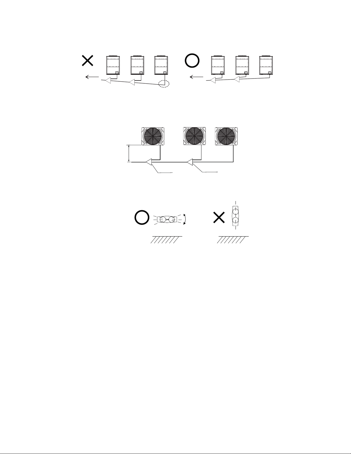
(5) For servicing, in case that the pipe is placed frontward of the outdoor unit, secure Min.19-11/16in.(500mm) between the
(6) Direction of Manifold Pipe
Place the Manifold Pipe horizontally toward the ground (within±15°) as shown in the figure.
(4) Place the outdoor unit pipe horizontally or with down gradient toward indoor unit side, or refrigerant oil may accumulate in the
Indoor Unit Side
Indoor Unit Side
Refrigerant oil accumulates in the pipe
Not more than 15
°
Min. 19-11/16in.500mm
Manifold pipe
Manifold pipe
Outdoor Unit
Outdoor Unit
Outdoor Unit
19-111600
15
Front Side
Bottom Side
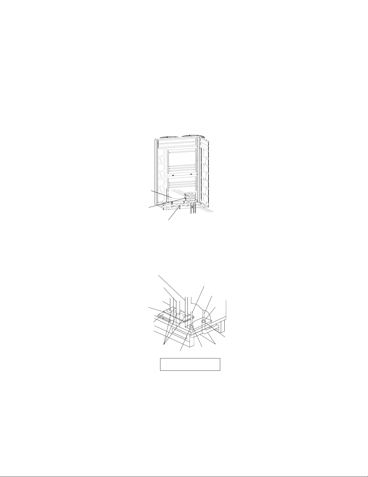
Apply insulation and check
that no clearance exists.
Piping Cover 1
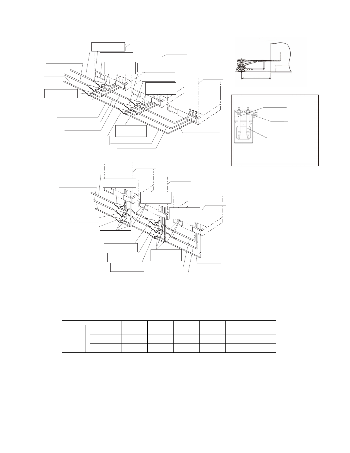
5.4 Piping Connection
Perform piping connection for each outdoor unit.
NOTE:
Ensure that the refrigerant pipes are connected to a unit in the same refrigerant cycle.
Prepare the refrigerant pipe in the field for the piping work.
Piping Direction
Fix the pipes adequately in order to avoid vibration and excessive force to the valve
(1) The pipes are available to connect in three directions from the bottom base.
Front side: gash the piping cover 1 with a boxcutter and connect directly through the service lid at the front unit
Bottom side: connect directly from the piping cover 2 on the bottom base
Rear side: connect from the piping cover 2 on the bottom base, then pass through the bottom base to open a hole
and connect.
●
Rear Side
Bottom Base
Power Supply Wiring
Seal
Seal
Seal
Rubber Bush
Conduit
Transmission Wiring
Liquid Piping
Gas Piping
(High/Low Pressure)
Gas Piping
(Low Pressure)
Rubber Bush
Packing
●
(2) Operation of the stop valve should be performed according to Item 5.4.1.
(3) If the piping is connected from the front side, completely seal the connecting piping with insulation pipe in
order to prevent the ingress of water or snow into the conduit.
(4) If the piping is connected from the bottom or rear side, completely seal the pipe passing through the bottom
of outdoor unit with insulation conduit in order to prevent ingress of water or snow into the conduit.
16
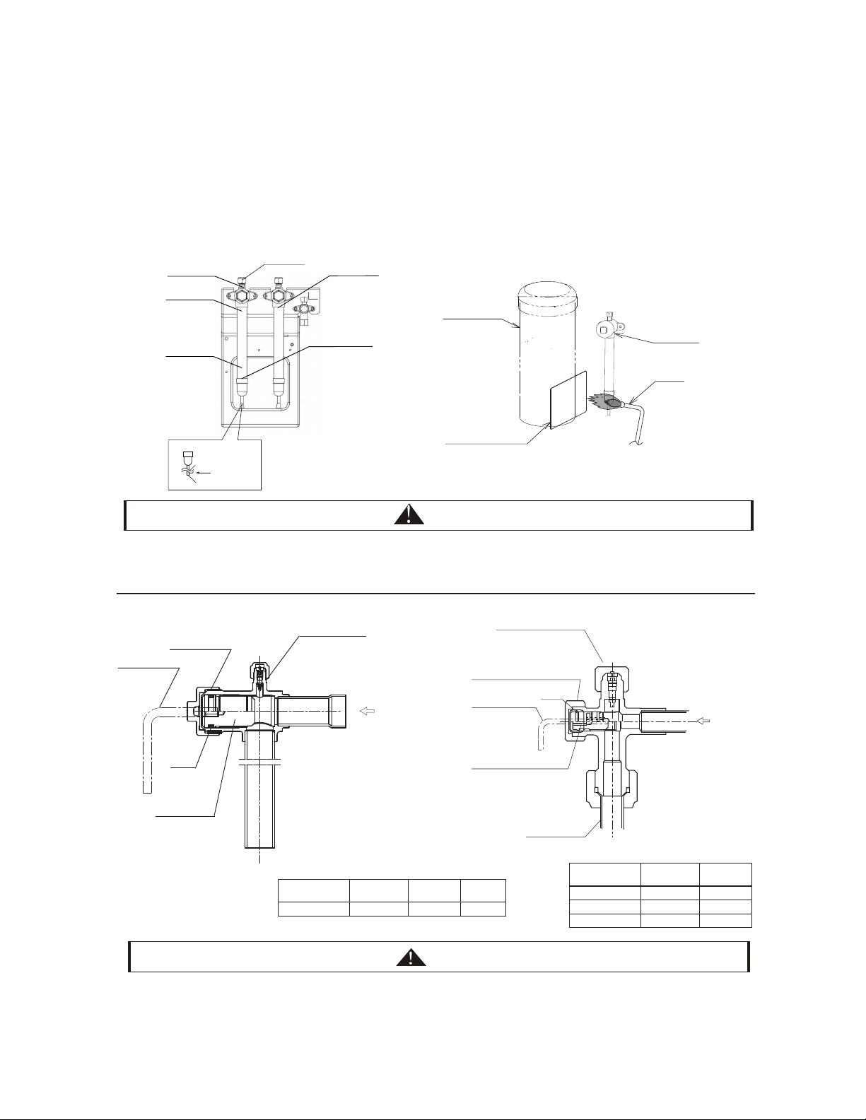
Sound-Proof Cover
Metal Plate for Protection
Burner
Stop Valve
Service Port
Gas Pipe
Brazing Portion of
Closing Pipe
Low Pressure
Gas Valve
Spindle
Stop valve is detailed as below:
Details of Closing Pipe
Cut from here
Φ1/4in. Pipe
Liquid Valve
<Gas Valve>
(1) Make sure that all the stop valves are closed completely;
(2) Connect the charging hose to the service port and release gas from the gas pipe;
(3) Cut off the end of the closing pipe (Φ1/4in.) and check that no gas exists inside the gas pipe;
(4) Remove the stop valve cover;
(5) Remove the closing pipe from the brazing portion by using a burner. Pay attention to the flame from the burner
not to burn the stop valve body.
CAUTION
Fig. 5.2
Check Joint for Service Port
Only the charge hose can be
connected. Tightening
torque: 33.3ft·lbs(15 N·m)
Cap Tightening torque: e
ft·lbs(N·m)
Spindle Valve
Counterclockwise......open
Clockwise......close
Refrigerant Piping
Refrigerant Pressure
5.4.1 Stop Valve
●
● Ensure that there is no gas inside the pipe when removing the closing pipe. Otherwise, the pipe may be blown out and
it may lead to injuries.
●
Protect the return oil pipe and sound-proof cover of the compressor with the metal plate when using a burner.
O-ring
High Low
Pressure Gas Valve
Model
Torque d
ft·lbs(N·m)
Torque e
72~96
5.2(7)
7.4(10)
22.1(30)
9.6(13)
25.8(35)
18.4(25)
120
144~192
●
Do not apply an excessively big force to the spindle valve at the end of opening, otherwise the stop valve will be
damaged.
●
At the test run, fully open the spindle. If not, the devices will be damaged.
CAUTION
ft·lbs(N·m)
Check Joint for Service Port
Only the charge hose can be
connected Tightening
torque: a ft·lbs(N·m)
Cap Tightening torque: b N·m
O-ring
Allen Wrench
Open/Close
spindle valve
Spindle Valve
Counterclockwise......open
Clockwise......close
Tightening torque: c ft·lbs
(N·m)
Refrigerant Pressure
Gas Valve
Model
Torque a
ft·lbs(N·m)
Torque b
72~192
11.1(15)
40.5(55)
ft·lbs(N·m)
Torque c
ft·lbs(N·m)
22.1(30)
Allen Wrench
Open/Close
spindle valve
Tightening torque: d ft·lbs
(N·m)

17
5.4.2 Piping Connection
(1)
Make sure that the stop valves are closed completely.
(2) Protect the compressor and sound-proof cover with metal plate when brazing the gas pipe as shown in Fig. 5.2. Pay
attention to the flame from the burner not to burn the stop valve body.
(3) Connect the indoor unit and the outdoor unit with refrigerant piping. Prevent the refrigerant piping from touching
weak parts of the building such as wall, ceiling, etc. Abnormal sound may give off due to vibration of the piping.
(4) As for the flaring work of the field pipe, use the specified tightening torque in Table 5.3. Purge nitrogen gas into the
pipe when brazing.
(5) Insulate the gas pipe and liquid pipe completely.
(6) Mount the piping cover equipped with the outdoor unit after the piping connection. If not, the unit may be damaged
due to the ingress of snow or rain water.
Table 5.3 Flare Nut Tightening Work
Required Tightening Torque
Pipe Size
Tightening Torque (ft·lbs(N·m))
Φ6.35 (1/4)
10~13(1418)
Φ9.53 (3/8)
25~31(3442)
Φ12.7 (1/2) 50~62(68~84)
Φ15.88 (5/8) 63~77(85~104)
Φ19.05 (3/4) 90~110(122~149)
NOTES:
< Front Side Piping Connection >
< Downward Piping Connection >
1. Ensure that the closing pipe of the gas stop valve(1 place) is removed firstly.
2. Refer to the item 5.2 for flaring work.
Construction Example
< Heat Pump System >
NOTE:
Min.19-11/16in.
(500mm)
Outdoor unit A
Outdoor unit B
Outdoor unit C
High/Low pressure Gas Piping
(Field-Supplied)
Liquid Piping
(Field-Supplied)
Manifold Pipe 1
(Liquid)
Bending Pipe
(Field-Supplied)
Manifold Pipe 2
(High/Low Pressure Gas)
Manifold Pipe 2(Liquid)
Liquid Piping
(Field-Supplied)
High/Low pressure
Gas Piping(Field-Supplied)
Outdoor unit B
Outdoor unit C
Outdoor unit A
High/Low pressure Gas Piping
(Field-Supplied)
Liquid Piping
(Field-Supplied)
Bending Pipe
(Field-Supplied)
Liquid Piping
(Field-Supplied)
High/Low pressure
Gas Piping(Field-Supplied)
High/Low pressure
Gas Piping(Field-Supplied)
Liquid Piping
(Field-Supplied)
(Field-Supplied)
Bending Pipe
Manifold Pipe 2(Liquid)
Manifold Pipe 2(Liquid)
This piping connection is NOT
used in heat pump system
(2-pipe)
There are three piping connections in the outdoor
units
In case of heat pump system, there are only two
piping connections.
Manifold Pipe 2
(High/Low pressure Gas)
Manifold Pipe 1
(High/Low pressure Gas)
Accessory Piping
(Field-Supplied)
Accessory Piping
(Field-Supplied)
Manifold Pipe 1
(High/Low pressure Gas)
<View-P>
High/Low Pressure
Gas Piping
Liquid Piping
< Heat Recovery System >
< Front Side Piping Connection >
< Downward Piping Connection >
NOTE:
The figure shows the case that the refrigerant pipes are pulled out from the front side piping
cover. They can be also pulled out from the bottom base hole.
Piping Size For Outdoor Unit
18
72 96 120 144 168
Low Pressure Gas 3/4(19.05) 7/8(22.2) 1(25.4) 1(25.4)
High/Low
Pressure Gas
5/8(15.88)
Liquid 3/8(9.53) 1/2(12.7)
Model (kBtu/h)
Piping
Size
(φmm)
a
Min.19-11/16in.
(500mm)
192
5/8(15.88)
Outdoor Unit A
Outdoor Unit B
Outdoor Unit C
Low Pressure Gas Piping
(Field-Supplied)
Low Pressure Gas Piping
(Field-Supplied)
Low Pressure Gas Piping
(Field-Supplied)
High/Low Pressure Gas
Piping (Field-Supplied)
High/Low Pressure Gas
Piping (Field-Supplied)
High/Low Pressure Gas
Piping (Field-Supplied)
Liquid Piping (Field-Supplied)
Manifold Pipe 2
(Liquid)
Liquid Piping (Field-Supplied)
Liquid Piping
(Field-Supplied)
Manifold Pipe 2 (Low
Pressure Gas)
Manifold Pipe 1 (Low
Pressure Gas)
Manifold Pipe 2 (High/
Low Pressure Gas)
Manifold Pipe 1 (High/
Low Pressure Gas)
Manifold Pipe
1
(Liquid)
Bending Pipe
Bending Pipe
(Field-Supplied)
(Field-Supplied)
(Field-Supplied)
(Field-Supplied)
Bending Pipe
Bending Pipe
Outdoor Unit C
Low Pressure Gas Piping
(Field-Supplied)
High/Low Pressure Gas
Piping (Field-Supplied)
Liquid Piping
(Field-Supplied)
Manifold Pipe 2 (Low
Pressure Gas)
Manifold Pipe 1 (Low
Pressure Gas)
Manifold Pipe 2 (High/
Low Pressure Gas)
Manifold Pipe 1 (High/
Low Pressure Gas)
Manifold Pipe 2 (Liquid)
Manifold Pipe 1 (Liquid)
Low Pressure Gas Piping
(Field-Supplied)
High Pressure Gas Piping
(Field-Supplied)
Liquid Piping
(Field-Supplied)
Outdoor Unit B
Accessory Pipe
Gas Accessory Pipe
(Field-Supplied)
(Field-Supplied)
(Field-Supplied)
(Field-Supplied)
Outdoor Unit A
Bending Pipe
Bending Pipe
unit:in.(mm)
3/8(9.53)
3/4(19.05)
7/8(22.2)
7/8(22.2)
7/8(22.2)
7/8(22.2)
1/2(12.7)
1/2(12.7)
1-1/8(28.6)
1-1/8(28.6)
Low Pressure Gas
Piping
There are three piping connections in outdoor
units
High/Low Pressure
Gas Piping
Liquid Piping
<View-P>
NOTE:
I.

6.Electrical Wiring
●Turn OFF the main power switch to the indoor unit and the outdoor unit and wait for more than 10 minutes before
electrical wiring or a periodical check is performed.
●Check to ensure that the indoor fan and the outdoor fan have stopped before electrical wiring work or a periodical
check is performed.
●Protect the wires, electrical parts, etc. from rats or other small animals. If not, rats may gnaw at unprotected parts,
which may lead to a fire.
●Avoid the wirings from touching the refrigerant pipes, plate edges and electrical parts inside the unit. If not, the
wires will be damaged and at the worst, a fire will break out.
●Use a medium sensing speed type ELB (Earth Leakage Breaker, activation speed of 0.1 sec. or less). If not, it will
cause an electric shock or a fire.
●Fix the cables securely. External forces on the terminals could lead to a fire.
●It is forbidden to use the terminal block of air conditioner power supply to extend power line to other indoor units .
Use the power distribution box to extend the power supply wiring on the inner side of the air conditioner. Pay
attention to the wiring capacity calculation, otherwise, the wiring capacity is too small and a fire may break out.
●Tighten screws with the following torque.
M4:0.7 to 1.0 ft·lbs(1.0~1.3 N·m)
M5:1.5 to 1.8 ft·lbs(2.0~2.4 N·m)
M6:3.0 to 3.7 ft·lbs(4.0~5.0 N·m)
M8:6.6 to 8.1 ft·lbs(9.0~11.0 N·m)
M10:13.3 to 17 ft·lbs(18.0~23.0 N·m)
6.1 General Check
(1)Make sure that the field-selected electrical components (main power switches, fuse, wires, conduit
connectors and wire terminals) comply with National Electrical Code (NEC).
●Supply electrical power to each outdoor unit. An ELB, fuse and main switch should be used for each
outdoor unit. Otherwise, it
may lead to an electric shock, or a fire may break out
●The power supply for the indoor unit and outdoor unit should be provided separately.
Connect a power supply wiring to each indoor unit to be connected to the same outdoor unit.
(2)Check to ensure that the power supply voltage is within ±10% of the rated voltage.
If the power supply voltage is excessively low, the system does not start due to the voltage drop.
(3) Check the size of the electrical wires.
The air conditioner may not operate properly under the following
.
●In case that the air conditioner has to share power transformer with device of high electricity consumption*
●In case that the power source wires for the device* and the air conditioner are adjacent to each other.
* lift, container crane, rectifier for electric railway, inverter power device, arc furnace, electric furnace, large-
sized induction motor and large-sized switch.
For the cases mentioned above, induction surge of the power supply wiring for the air conditioner may occur
due to a rapid change in electricity consumption of the device and an activation of switch. Therefore check the
local regulations and standards before performing electrical work in order to protect the power supply wiring
of the air conditioner.
(5)Check to ensure that the earth wire of the outdoor unit is connected.
WARNING
19
(2)
(3)
(4)
6.2 Electrical Wiring Connection
WARNING
20
Table 6.1 Minimum Wire Sizes for Power Source on Field
Model
Outdoor Unit Inverter 1 Inverter 2 Fan Motor
Hz Voltage Max. Min. MCA MOP Max. Fuse MOC MOC FLA
(Hz) (V) (V) (V) (A) (A) (A) (A) (A) (A)
CHV6-072URB 60 208/230 253 188 34.3 45 25.2 - 2.8
CHV6-096URB 60 208/230 253 188 41.2 50 30.7 - 2.8
CHV6-120URB 60 208/230 253 188 49.3 60 37 - 1.5×2
CHV6-144URB 60 208/230 253 188 60.1 80 24.2 24.2 2.8×2
CHV6-168URB 60 208/230 253 188 62.3 80 25.2 25.2 2.8×2
CHV6-192URB 60 208/230 253 188 78.1 100 32.2 32.2 2.8×2
45
50
60
80
80
100
Model
Wiring Size
Power Supply
Wiring
Ground
Wiring
Communication
Cable
(AWG) (AWG) (AWG)
8 18
8 18
6 18
4 18
4 18
2 18
CHV6-072URB
CHV6-096URB
CHV6-120URB
CHV6-144URB
CHV6-168URB
CHV6-192URB
8
8
6
4
4
2
MCA: Minimum Circuit Ampacity (A)
MOP: Maximum Overcurrent Protective Device (A)
MOC: Maximum Operating Current (A)
FLA: Fan Motor Running Ampacity (A)
Note the following when selecting wiring:
● Use the charts below to select appropriate sized breakers / fuses / overcurrent protection switches and
wiring in accordance with local codes.
(2) Electrical Characteristics
● Ensure communication cable is a minimum of AWG18 (0.82mm
2
), 2-Conductor, Stranded Copper.
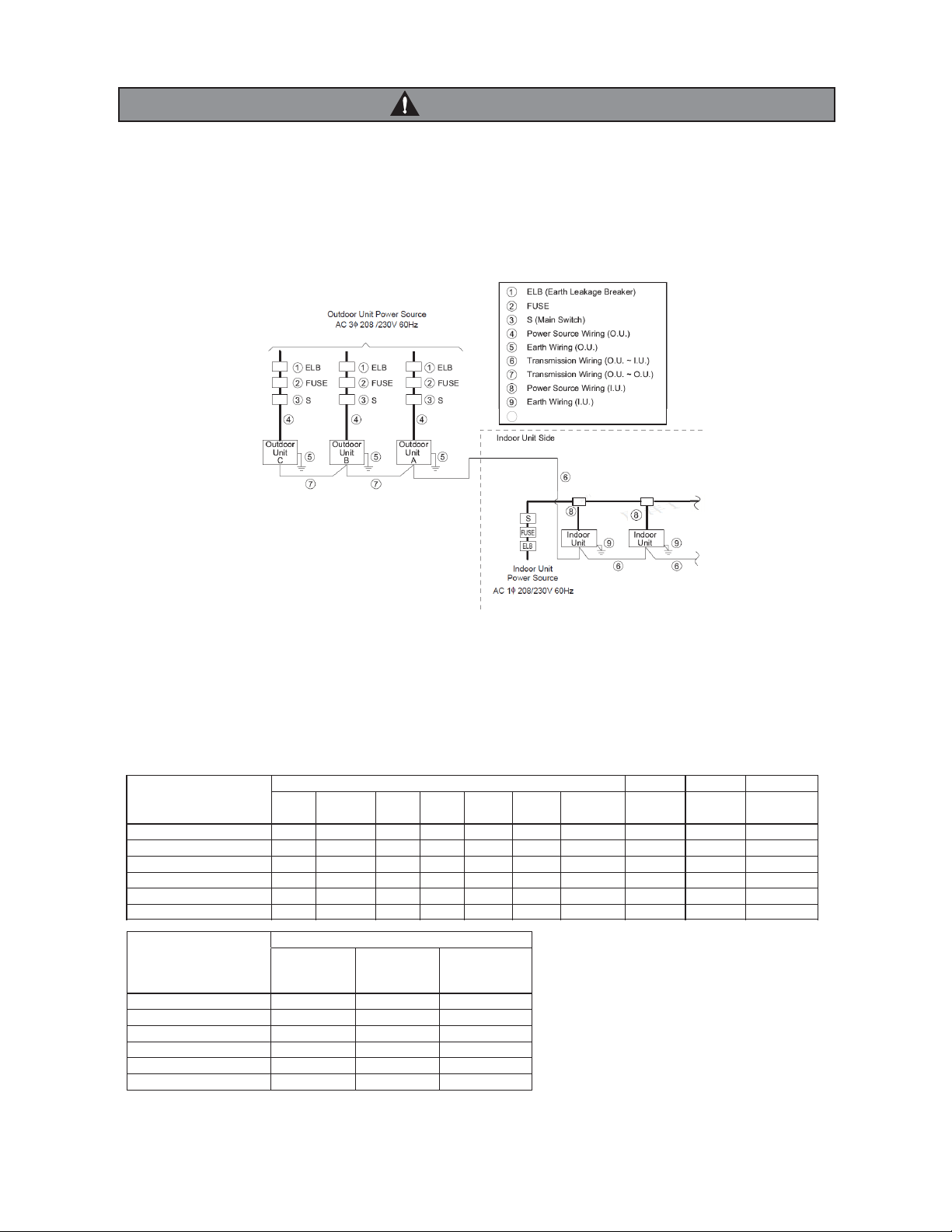
The ELB (earth leakage breaker), FUSE and S (main switch) must be installed to the each power
source of outdoor unit. If not, it may cause an electrical shock or a fire.
Perform the electrical work according to the regulations of each region and this manual
NOTE:Supply the power source of outdoor units and indoor units respectively.
(1) Power Supply Wiring
Supply the power sources to the each outdoor unit respectively. Power source wiring is fundamentally according to
this method.
Distribution Box
10

CAUTION
Install a multi-pole main switch with a space of 1/8in.(3mm) or more between each phase.
NOTES:
1) When the power supply wiring is longer, select the minimum wiring size of which the voltage drop is within 2%.
2) Power supply voltage should be satisfied with the followings:
supply voltage: rated voltage within +10%
starting voltage: rated voltage within -15%
operating voltage: rated voltage within ±10%
imbalance between phases: within 3%
3) Do not connect the earth wire to the gas pipe, water pipe, lightening conductor.
Gas pipe: an explosion and ignition may occur when gas leaks.
Water pipe: there is no effect of earth wire when a hard vinyl pipe is used.
Lightening conductor: the earth electric potential abnormally increases when a lightening conductor is used.
6.3 Electrical Wiring Connection
Connect the electrical wirings according to the following figure.
21
the cord band base onto the with the short screw, the cord band base and short screw are .
in the fastener pouch
wiring through the hole on the mounting plate and mount the cord band with the long screw to secure power
wiring and earth wring; then connect power lines to Terminal on TB1, and earth wire connect to the terminal in the
electrical control box.
rap transmission wiring between indoor and outdoor units twice around the small magnet ring in electrical
accessory pouch, then connect to Terminal 1 and 2 of TB2 on PCB1. As for transmission wiring between
outdoor units of the same refrigerant system, please connect to Terminal 3 and 4 of TB2 on PCB1.
Tighten screws on the terminal board
Earth Wire
for O.U.
to O.U.
TB2
PCB1
Shielded Twist
Pair Cable from
Indoor Unit
to Outdoor Unit
Shielded Twist
Pair Cable for
between Outdoors
Transmission
Cord Clamp
for I.U.
to O.U.
1
2
3
4
L2 L3L1
Ground
Wiring
Terminal Block for
Power Supply Wiring
(TB1)
Ground Wiring
Terminal (Connect
securely cable.)
Attach
insulation
sleeve.
Power Supply WiringΦ1-/32(Φ43.7)
Operating Wiring
Φ(Φ)
(Knock-out Hole)
NOTE: seal hermetically the entry of the conduit by using putty
or etc. to avoid the ingress of water.
Cord Band
Long Screw
Cord Band Base
Short
Screw
Cord Band
NOTE: refer to the above picture for the installation of cord band and cord band
base. all parts above are in the fastener pouch
Terminal Board for
Transmission Wiring
Cord Clamp
Terminal Board
For Power Supply
(for Transmission Wiring)
Transmission Wiring
(install small magnet ring)
Cord Clamp
Power Supply Wiring
(install big magnet ring)
(for
Wiring)
Cord Clamp
Connection Hole of
Transmission Wiring
Connection Hole of
Power Supply Wiring
Earth Wiring
Cord Band
22
Pay attention to the followings to run through the cables under the unit using conduit tube. (The guard
plater is required to remove before performing piping and wiring works.)
1
1
.
.
Do not lead the power supply wiring and transmission wiring through the same conduit. Moreover, keep a
distance of at least 1-31/32(50mm) between the power supply wiring and transmission wiring
2
2
.
.
Cut cross line at rubber bush and securely attach it to the knock-out hole for cable protection.
3
3
.
.
Attach the guard plate to avoid entrance of rats or other small animals into the unit.
4
4
.
.
Avoid the wirings from touching the refrigerant pipes, plate edges and electrical parts inside the unit.
Completely seal the end of conduit tube with sealing materials to avoid the ingress of rain into the conduit.
Make a drain hole at the lowest part of the conduit tube.
CAUTION
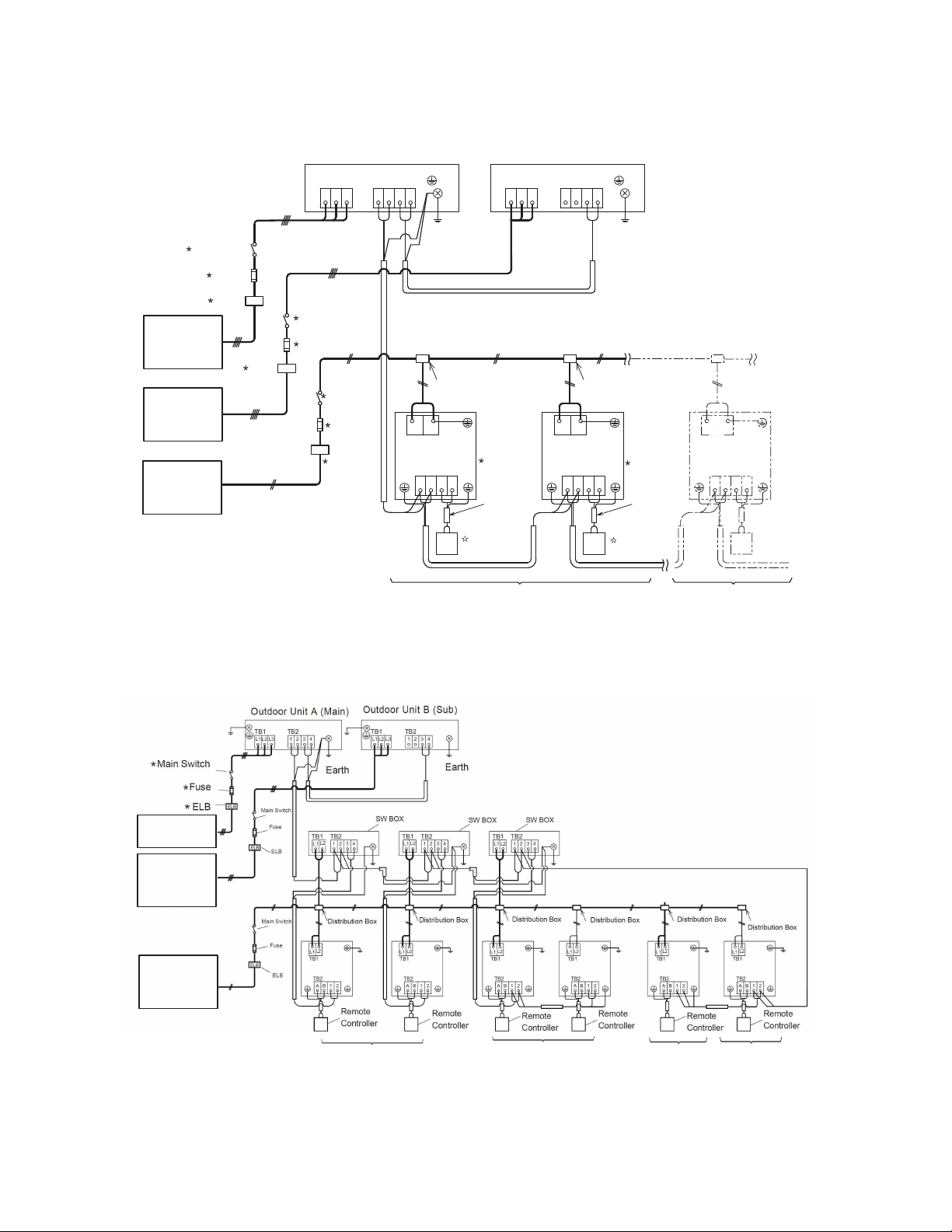
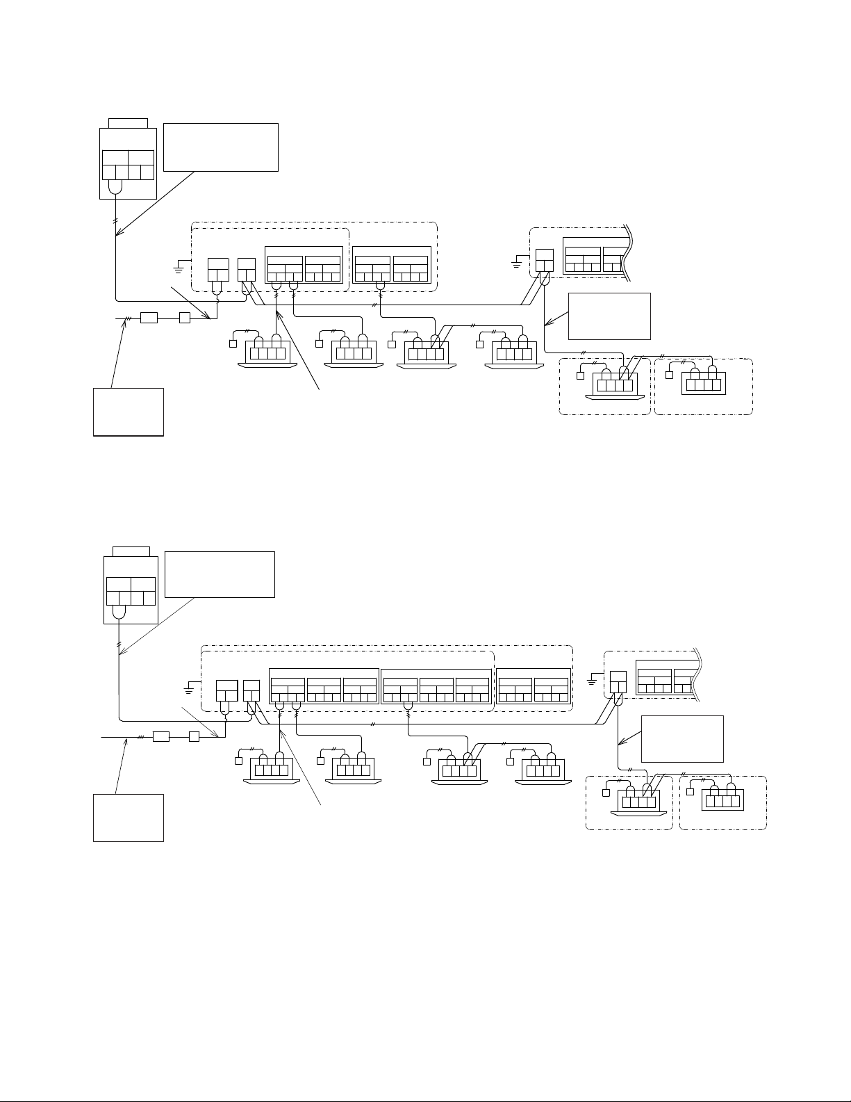
(1)Connect power supply wiring to each outdoor unit. Connect an ELB, fuse and main switch () to each outdoor
unit.
(2)Connect power supply wiring to each indoor unit to be connected to the same outdoor unit. Connect an ELB,
fuse and main switch() to each indoor unit group.
(
(
3
3
)
)
Connect the transmission wiring between indoor units and outdoor units, as shown in figure.
Connect the transmission wiring in the same refrigerant cycle. (In case that the refrigerant pipe of indoor unit
is connected to the outdoor unit, connect the transmission wiring to the same indoor unit.) Connecting the
refrigerant pipe and transmission wiring to the systems of different refrigerant cycle may lead to malfunction.
(
(
5
5
)
)
Use 2-core lead wires such as shielded twist pair cable for the transmission wiring. (Do not use 3-core or
over.)
(
(
7
)
)
The transmission wiring is required to be separated from the power supply wiring. Keep a distance of at least
1-31/32in.(50mm) between the transmission wiring and the power supply wiring, and also a distance of min.
49.2ft.(5m) between the transmission wiring and power supply wiring of other electrical device. If the above is
not secured, put the power supply wiring into the metal conduit to separate from other wirings.
Connect the following transmission wiring to Terminal 1 and 2 of TB2 in the outdoor unit A (main unit).
For the combination modules, DSW settings of Main and Sub are required.
Alarm occurs if the transmission wires between outdoor units are connected to Terminal 1 and 2 for H-
NET.
In case that alarm is indicated on the LCD of Main outdoor unit, follow the "7-segment" display when the
ain outdoor unit checking.
Perform function setting from Main outdoor unit.
When indoor units are connected to the SW BOX, refer to technical handbook for wiring.
Tightly secure the power source wiring by using the cord clamp inside the unit.
.4 Electrical Wiring Connection of The System
(9)Do not connect the power supply wiring to terminal board for transmission wiring (TB2). Printed circuit
board may be damaged.
(10) Connect the earth wire for outdoor/indoor units. The earth wiring work under the condition of 100 Ω
(max.) ground resistance should be performed by a qualified person.
NOTES:
● between outdoor unit and indoor unit
● between outdoor unit and indoor unit in other refregerants cycles
CAUTION
4
4
.
.
Screw
S
ize Tightening Torque
M4
M5
1.5~
1.8 ft·lbs(2.0~2.4N·m)
M6
M8
M10
3.0~3.7 ft·lbs(
4.0~5.0N·m)
6.6~8.1 ft·lbs(9.0~11.0N·m)
13.3~17 ft·lbs(18.0~23.0N·m)
0.7~1.0 ft·lbs(1.0~1.3N·m)
<Tighten screws for the terminal board according to the following table.>
1.
2.
3.
4.
5.
(3)
(4)
(5)
(7)
(8)
1.
2.
3.
4.
TS
6 UH-T
No.1 System Indoor Units
(or Water Modules)
Remote
Controller
ELB
Main Switch
Main Switch
Remote
Controller
No.0 Unit
TB2
(Shielded
Twist Pair
Cable)
No.1 Unit
Distribution Box
Fuse
ELB
Fuse
TB1
208/230V
3~ 60Hz
Outdoor Unit A (Main)
TB1
TB2
L1 L2 L3 1 2 3 4
Outdoor Unit B (Sub)
TB1 TB2
1234L1 L2 L3
12AB 12AB
TB2
TB1
ELB
ELB
ELB
Earth
Earth
ELB
Main Switch
Fuse
Distribution Box
Remote
Controller
(Shielded
Twist Pair
Cable)
Remote
Controller
No. 0 System Indoor Units (or Water Modules)
208/230V
3~ 60Hz
< Heat Pump System & Heat Recovery System Without Switch Box >
< Heat Recovery System with Switch Box>
For Single Branch SW BOX
Heat Recovery Indoor Units
(or Water Modules)
Cooling Only
Indoor Units
23
Heating Only
Water Modules
Heat Recovery Indoor Units
Connected to the same branch
208/230V
3~ 60Hz
208/230V
3~ 60Hz
208/230V
1~ 60Hz
208/230V
1~60Hz
L1
L2
L1 L2
For Multi Branch SW BOX
24
32 41
H-LINK
Outdoor
Connect communication
cable from outdoor unit to
the outdoor terminal
block(TB2) in Switch Box.
Cooling Only Indoor Unit
Indoor Unit A Indoor Unit B
Communication cable
RCS:Remote Control Switch
( )
Indoor Units F
When multiple Indoor Units are connected to the
same branch, they are controlled with same operation
mode.
SPMBB-8/85
SPMBB-4/45
BA21
BA21
BA21
BA21BA21
Switch Box
Outdoor
1 2
TB2
Outdoor
1 2
TB2
Indoor
Indoor
TB3 TB4
PCB1
AB C
3456 78
TB3 TB4
PCB2
3456 789
EF GH
Indoor Indoor
TB3 TB4
PCB1
3 4 5 6 7 8 9 10
AB CD
RCS
RCS
RCS
RCS
…
RCS
…
Power
Supply
L2
TB1
ELB S
Main Switch
and Fuse
Earth
Leakage
Breaker
Power Supply Wiring
Indoor Indoor
10
(a) SPMBB-4/45/SPMBB-8/85
Heating Only Water Module
BA21
RCS
(Non-Polarity)
(DC5V)
or Water Module A
or Water Module B
Connect communication
cable from cooling only
water module to the outdoor
terminal block (TB2) in
Switch Box.
indoor unit and heating only
1234
H-LINK
Outdoor Unit
Outdoor
Connect communication cable from
outdoor unit to the outdoor terminal
block(TB2) in Switch Box.
Cooling Only Indoor Unit
Indoor Unit A Indoor Unit B
Indoor Units H
RCS:Remote Control Switch
( )
SPMBB-16/85
SPMBB-12/85
BA21BA21
BA21BA21
1 2
TB2
TB5
1112
EF
Indoor
TB3 TB4
PCB1
3 4 5 6 7 8 9 10
AB CD
RCS
RCSRCS
……
RCS
TB5
1112
GH
TB3 TB4
PCB2
3 4 5 6 7 8 9 10
I
J
KL
TB3 TB4
PCB3
3 4 5 6 7 8 9 10
MN 0 P
Power
Supply
L2
TB1
ELB S
Main Switch
and Fuse
Earth
Leakage
Breaker
Power Supply Wiring
Outdoor
Indoor Indoor
Indoor
Indoor Indoor
Indoor Indoor
(b) SPMBB-12/85/SPMBB-16/85
Switch Box
1 2
TB2
TB3 TB4
PCB1
AB C
3456 78
Outdoor
Indoor Indoor
Heating Only Water Module
BA21
RCS
BA21
RCS
Communication cable
(Non-Polarity)
(DC5V)
or Water Module A
or Water Module B
When multiple Indoor Units are connected to the
same branch, they are controlled with same operation
mode.
Connect communication
cable from cooling only
water module to the outdoor
terminal block (TB2) in
Switch Box.
13 14
13 14
indoor unit and heating only
L1
L1
208/230V
1~ 60Hz
208/230V
1~ 60Hz
●
NOTE
By using switch DSW4, the unit starts or stops 10 to 20 seconds after the switch is operated.
Number this outdoor unit to distinguish from other outdoor units for service and maintenance.
And write the number in the box on the right.
Do not touch any other electrical parts when operating switches on the PCB.
6.5 DIP Switch Setting of Outdoor Unit
TURN OFF all power sources before setting.
Without turning OFF, the switches do not work and the contents of the setting are invalid. However, DSW4-
No.1, 2, 4 can work during power source is ON. The mark of “ ” indicates the position of dip switches.
●
NOTES:
• When multiple indoor units are connected to the same single SW BOX, they are controlled with the same operation
mode.
• When multiple indoor units are connected to the same branch of the multi SW BOX, they are controlled with the
same operation mode.
• Do not apply excessive voltage to the communication cable DC5V (non-polarity) between the outdoor unit and the
SW BOX, between the SW BOX and the indoor unit or between SW BOXES.
• Use 2-conductor (at the most) shielded communication cable.
• Connect the communication cable for the outdoor unit to terminals “1” and “2” on TB2 in the SW BOX.
• Connect the communication cable for the cooling only indoor unit or heating only water module to the terminal “1” and
“2” on TB2 in the SW BOX.
• For a SW BOX in the same refrigerant cycle, an electrical power supply can be supplied by one main switch.
• Do not connect the power supply wiring to the terminal block for transmission cable.
• Connect the ground wiring for the outdoor/indoor units and SW BOX. When ground resistance is less than 100 Ω,
ground wiring work should be performed by the qualified electrician.
• Do not run communication cable along with power supply wirings in the SW BOX. Separate communication cables
from the power supply wirings.
• Water module should be connected to an exclusive branch of the SW BOX. .
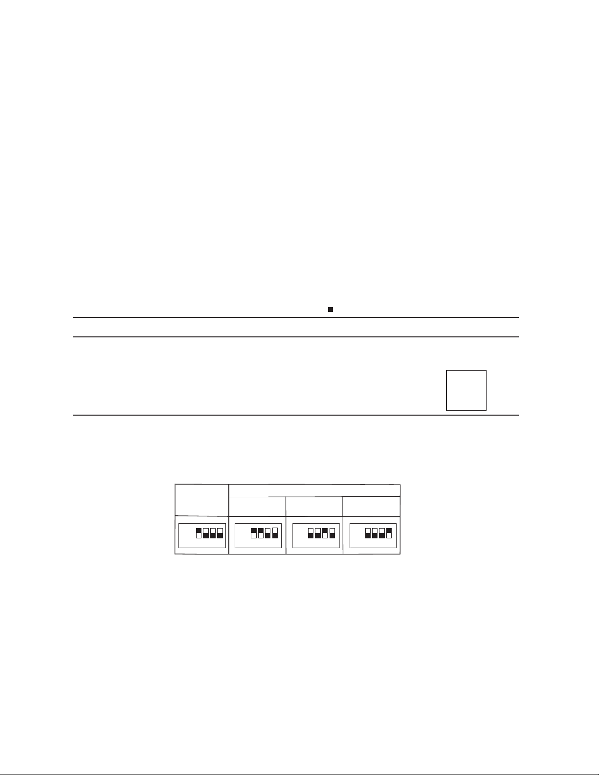
Setting for Transmitting
It is required to set the outdoor unit Nos., refrigerant cycle Nos. and terminal resistance for this H-NET system.
Setting of Outdoor Unit No.
In case of the combination module, set DSW6 as shown below.
●
●
ON
OFF
1 2 3 4
ON
OFF
1 2 3 4
ON
OFF
1 2 3 4
ON
OFF
Basic Unit
(Before Shipment)
Combination Module
(No.0) (Main)
(No.2)
(No.3)
Outdoor Unit A
Outdoor Unit BOutdoor Unit C
1 23
25
●
●
Setting for British Unit
Before shipment, No.4 pin of DSW7 is set at “OFF”, metric units can be used;
set the No.4 pin of DSW7 at “ON” to use the British units.
OFF
ON
OFF
1 2
DSW10
Outdoor
DSW10
Outdoor
DSW10 DSW10DSW10 DSW10
12
DSW10
1 2
DSW10
ON
OFF
12
DSW10
ON
OFF
Setting of Terminal Resistance
DSW10
Set Position 1 on DSW10 to
OFF to cancel setting of
terminal resistance.
Set Position 1 on DSW10 to
OFF to cancel setting of
terminal resistance.
Outdoor Unit
Outdoor Unit
(Main) (Sub)
(Sub)
(Main) (Sub)
Outdoor Unit
Outdoor Unit
Communication cable
(H-NET)
Communication cable
(H-NET)
Communication cable
(H-NET)
Indoor
Unit
Indoor
Unit
Indoor
Unit
Indoor
Unit
Unit A
Unit B
Unit C
Outdoor
Unit A
Unit B
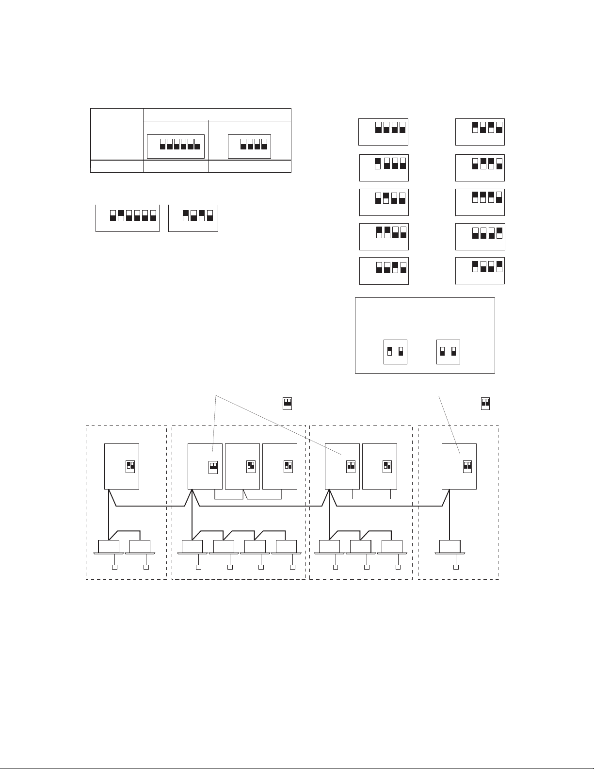
1 2 3 4 5 6
ON
OFF
DSW1 DSW8
1234
ON
56
OFF
Setting Switch
10 digit 1 digit
Outdoor Unit
1 2 3 4
ON
OFF
1234
ON
OFF
Turn ON No. 1 and No. 3 pins
(The settings in binary system shall be
only valid for 0~9 and it will alarm once
exceeding.)
0~9 Binary System Dip Setting Method for DSW8
Setting of Refrigerant Cycle No.
In the same refrigerant cycle, set the refrigerant cycle No. for the outdoor units as shown below.
NOTE: In the same refrigerant cycle, set the same refrigerant cycle No. for the outdoor unit and the indoor unit.
Ex: In Case of Setting Refrigerant Cycle No. 25
DSW1 and DSW8 setting before shipment is 0.
Maximum in setting refrigerant cycle No. is 63.
Setting of Terminal Resistance
Before shipment, No.1 pin of DSW10 is set at the “ON”side. In
the case that the outdoor units quantity in the same H-NET is
2 or more, set No. 1 pin of DSW10 at the “OFF” side from the
2nd refrigerant group outdoor unit. If only one outdoor unit is
used, no setting is required.
1 2
1 2
Outdo
or
●
●
26
0 5
6
7
8
4
1
2
3
9
1 2 3 4
ON
OFF
ON
OFF
1 2 3 4
ON
OFF
1 2 3 4
ON
OFF
1 2 3 4
ON
OFF
1 2 3 4
ON
OFF
1 2 3 4
ON
OFF
1 2 3 4
ON
OFF
1 2 3 4
ON
OFF
1 2 3 4
ON
OFF
1 2 3 4
Turn ON No. 2 pins
ON
Before Shipment
Cancellation
12
12
12
1 2
1 2
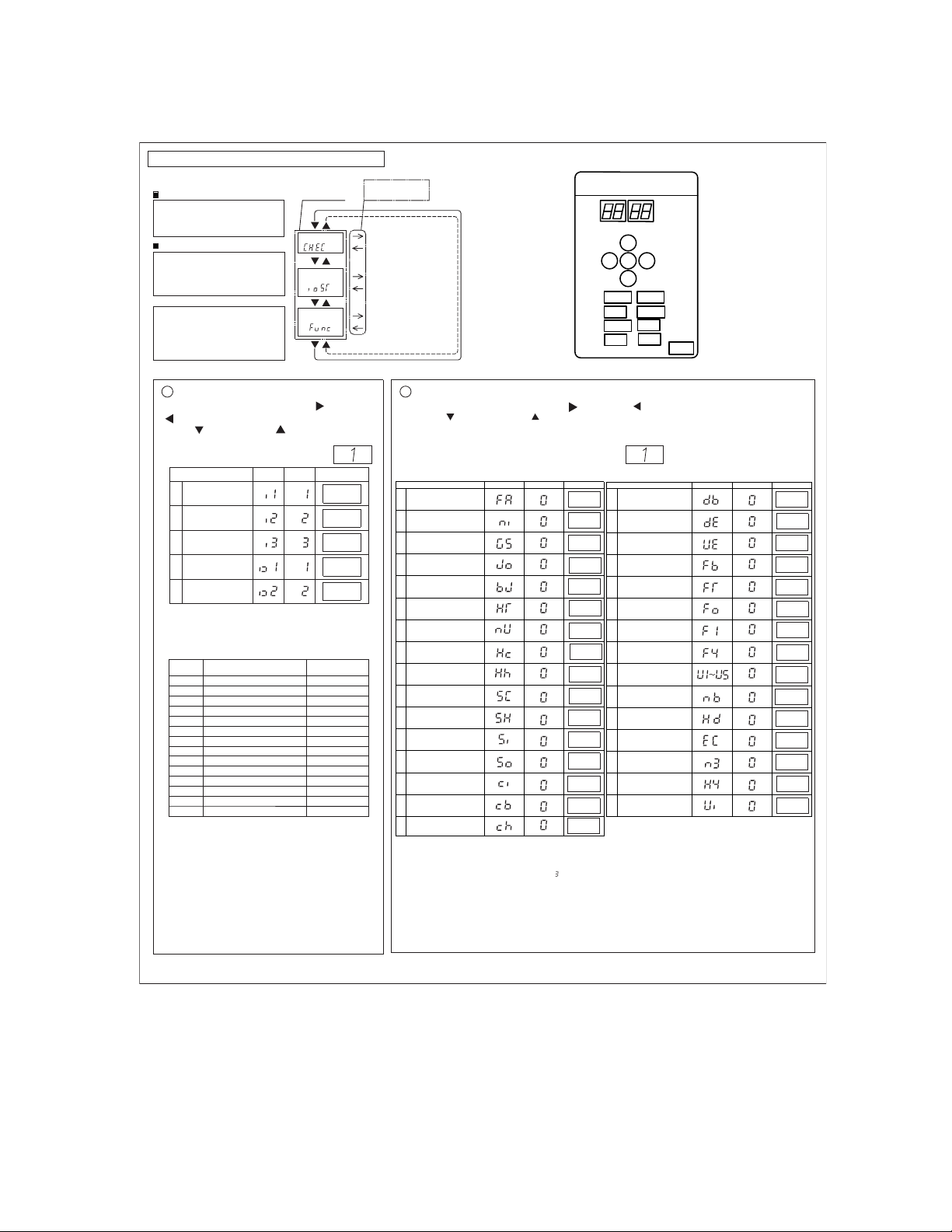
2
1
2
3
4
5
SEG1SEG2
1
“
”
(Setting before shipment)
Before shipping, the input/output function settings are
specified to each input/output terminal according to above table.
Function Setting
External Input/Output and Function Setting
Start of Setting
Turn ON DSW4-No.4.
Press PSW1 for at least3 seconds.
“Menu Mode” will be indicated.
End of Setting
Press PSW1 for at least 3 seconds.
The display indication become to
normal indication.
Turn OFF DSW4-No.4.
NOTE:
Release “Menu Mode” after the
setting is completed.
Otherwise, the air conditioner
may not operate properly.
Menu Mode
Press PSW1 once.
Check Mode
External Input and
Output
Function Setting
For more details,
refer to “Checking of
Outdoor Unit by PCB”
in the Service Manual.
For the setting mode,
refer to ① below.
For the function setting,
refer to ② below.
By pressing the push-switches PSW3 ( )and PSW5
( ), the function No. can be selected.
PSW4 ( ): forward, PSW2 ( ): backward
Fill out the selected function setting No. in
the box of the table as shown on the right.
<Example>
Item
SET
Input Setting 1
Input Setting 2
Input Setting 3
CN17[1-2 pin]
CN17[2-3 pin]
CN18[1-2 pin]
Input Setting 1
CN16[1-2 pin
Input Setting 2
CN16[1-3 pin]
The same input/output function setting can not be set to
different input/output terminals.
If set, a setting of larger function number is became invalid.
˷Function Setting˹
By pressing the push-switches PSW3 ( ) and PSW5 ( ), the setting can be changed.
PSW4 ( ): forward, PSW2 ( ): backward
Refer to the Technical Catalog for more details.
Fill out the selected function setting No. in the
space of the table as shown.
LJExample Lj
●
”
[External Input and Output Setting]
Setting External Input/Output Functions
“
“
”
SEG2 SEG1
PSW3
PSW2
PSW1
PSW4
PSW5
DSW6
DSW5
DSW4
DSW2
DSW3
DSW7
DSW1
DSW8
DSW10
Arrangement of Dip
Switch Setting
Note:
(1)The function setting of "n3" must be set to correct value according to the quantity of water module connected,
otherwise, ALARM 37 may be triggered. (For example, in case of the quantity of water module in a system is
three, then the value of "n3" should be set to " ". )
(2)The function setting of "H4" must be set to correct value according to the type of water module connected:
H4=0 (default) : water module should be used in a three pipes heat recovery system.
H4=2: water module should be used in a two pipes heat pump system.
27
(2)The function setting of "Ui" can be set according to application requirement:
Ui=0 (default) : performance balance between indoor unit and water module.
Ui=1: indoor unit has priority on performance.
SEG2 SEG1 SET
1
Fan Intermittent Operation
durin
g Heating Thermo-OFF
2
Night-Shift
3
Cancellation
of
Outdoor
Ambient Temperature Limit
4
Defrost
for
Cold Area
(Chan
ge of Defrost Condition)
5
SLo (Fan
Speed)
Defrost Setting
6
Canc
ellation
of
Hot Start
7
Prior
ity
Capacity Mode
8
Frequency Control
(
Control Target Value for
Cool
ing Compressor)
9
Frequency Control
(Control Target Value for
Heating)
10
Indoor
Expansion Valve
(Control Target Value for
Cooling)
11
Indoor
Expansion Valve
(Control Target Value for
Heating)
12
Indoor Expansion Valve
(Opening during Heating
Operation Stoppage)
13
Indoor Expansion Valve
Opening during Heating
Thermo-OFF
14
Indoor Expansion Valve
Initial Opening during Heating
Thermo-ON
15
Indoor Expansion Valve
Initial Opening for Cooling
16
Outdoor Expansion Valve
Initial Opening for Heating
Item
SEG2 SEG1 SET
17
Sound Reduced Function
18
Demand Function Setting
19
Wave Function Setting
20
Protection of Decrease in
Outlet Temperature for Cooling
21 Reserved
22
Adjustment of Fan Rotation
(for multiple installation)
23
Min. Indoor Exp-Valve
Opening Setting at Heating
Functions SW-OFF
24 Snow Model Setting
25 Indoor VIP Function
26 Automatic Night-Shift
27
Height Difference
Setting
28
Economic Fuction
Setting
29
Quantity of Water
Module Connected
30 Type of Water Module
31
Performance Balance
between Indoor Unit and
Water Module
Item
10
1
2
4
5
6
7
8
9
11
12
13
-
-
-
-
-
-
-
-
-
Function
Input
No.
Output
Fixing Heating Operation Mode
Demand Stoppage
Forced Stoppage
Demand Current Control 40%
Demand Current Control 60%
Demand Current Control 70%
Demand Current Control 80%
Demand Current Control 100%
Low Noise Setting 1
Low Noise Setting 2
Low Noise Setting 3
Fixing Cooling Operation Mo
de
Compressor ON Signal
Outdoor Fan Motor Start/Stop
Frost Signal
3
Warning signal
0
No set
No set
Operation Signal

7.
Additional Refrigerant Charge
7.1
Air-Tight Test
Liquid Valve
Cap
Tightening Torque: b N·m
O-ring
Hexagonal Wrench
Used to open/close
spindle valve
Refrigerant
Pressure
Spindle Valve
Counterterclockwise......Open
Clockwise......Close
Refrigerant Piping
<Gas Valve>
Tighening Torque: a N·m
Procedure
Completion of
Ref. Piping
Charging
Nitrogen Gas
Check of Pressure
Decrease
Pass
Fix Leakage
(1)Check to ensure that the stop valves are closed completely before air-tight test.
<Tightening Check of Stop Valves>
After connecting the pipe, remove the cap of stop valve for liquid.
Check Joint for Service Port
For charging additional refrigerant only
Valve-closing torque: 11.1ft·lbs (15 N·m)
(2) Connect the indoor units and the outdoor unit with field-supplied refrigerant piping.
Suspend the refrigerant piping at specified points and prevent the refrigerant piping from touching weak
parts of the building such as wall, ceiling, etc.. Vibration of the piping may give abnormal sound.
(3) Connect the manifold gauge to a vacuum pump or a nitrogen cylinder and the check joint of the
liquid stop valves and gas stop valves with charging hoses.
(4) Apply nitrogen gas pressure of 601psi(4.15MPa).
Do not open the stop valves.
(5) Check for any gas leakage at the flare nut connections, or brazed parts by use of a foaming agent or
gas leak detector.
(6) Mount the piping insulation materials after connecting the pipe.
DANGER
Be sure to use Nitrogen Gas for air-tight test. If other gases such as oxygen gas, acetylene gas or
fluorocarbon gas are accidentally used, it may cause explosion or gas intoxication.
28
Model
Torque a
ft·lbs(N·m)
Torque b
72~96
5.2(7)
7.4(10) 22.1(30)
9.6(13) 25.8(35)
18.4(25)
120
144~192
ft·lbs(N·m)
<Liquid Valve>
Check Joint for Service Port
Only the charge hose can be
connected
Tightening torque: a ft·lbs(N·m)
Cap Tightening torque: b N·m
O-ring
Allen Wrench
Open/close
spindle valve
Spindle Valve
Counterclockwise......open
Clockwise......close
Tightening torque: c ft·lbs
(N·m)
Refrigerant Pressure
Gas Valve
Model
Torque a
ft·lbs(N·m)
Torque b
72~192
11.1(15)
40.5(55)
ft·lbs(N·m)
Torque c
ft·lbs(N·m)
22.1(30)

Fig. 7.1 Air-Tight Test
(1) Connect manifold gauge and vacuum pump to the check joints.
(2) Continue vacuum pumping for one to two hours until the pressure reaches
-14.5Psi(-0.1MPa /-756mmHg)or lower.
After vacuum pumping, stop the valve of manifold gauge, stop the vacuum pump and leave it for one hour.
Check to ensure that the pressure in the manifold gauge does not increase.
(3) Tighten the cap of check joint after vacuum pumping.
NOTES:
1. If tools or measuring instruments come into contact with the refrigerant, use the tools or the
measuring instruments exclusively for R410A.
2. If vacuum degree of -14.5Psi(-0.1MPa /-756mmHg) is not available, it is considered that there is a
gas leakage. Check for any gas leakage once again. If no leakage exists, operate the vacuum
pump for one to two hours.
7.2 Vacuuming
29
Stop Valve
(Liquid Piping)
Stop Valve
(High/Low Pressure Gas Piping)
Stop Valve
(Low Pressure Gas Piping)
High/Low Pressure Gas Piping
Liquid Piping
Insulation
Switch BOX
[Cover the gas and liquid piping with insulation.]
Switch BOX
Outdoor Unit
Vacuum Pump
Siphonic Refrigerant Cylinder
(R410A)
Weigher
Nitrogen Tank
(for Nitrogen Blow during Brazing
and Air Tight Test)
Indoor Unit
Manifold Pipe
Manifold
Gauge
Insulation
Outdoor Unit
Stop Valve
Manifold
Gauge
Vacuum Pump
Nitrogen Tank
(for Nitrogen Purging during
Brazing and Air Tight Test)
Siphonic Refrigerant Cylinder
(R410A)
Weigher
High/Low
Pressure Gas Piping
Liquid Piping
(Liquid Piping
Stop Valve
(High/Low Pressure Gas Piping)
Stop Valve
(Low Pressure Gas Piping)
Manifold Pipe
Insulation
Indoor Unit
(or Water Module)
[Cover the gas and liquid piping with
insulation.]
(or Water Module)
Low Pressure
Gas Piping
< Heat Pump System >
< Heat Recovery System >
Stop Valve
Insulation
(Field-Supplied)
Refrigerant Piping
(Field-Supplied)
Fig. 7.2 Insulation on Pipes
Insulate the refrigerant pipes as shown in Fig.7.2. After
connecting the refrigerant piping, seal the refrigerant pipes
by using the field-supplied insulation material. Insulate the
unions and flare nuts at the piping connections completely.
Insulate the liquid piping and gas piping completely to
avoid decreasing of performance and dewing on the
surface of the pipe.
●
CAUTION
(1)
(2)
(3)
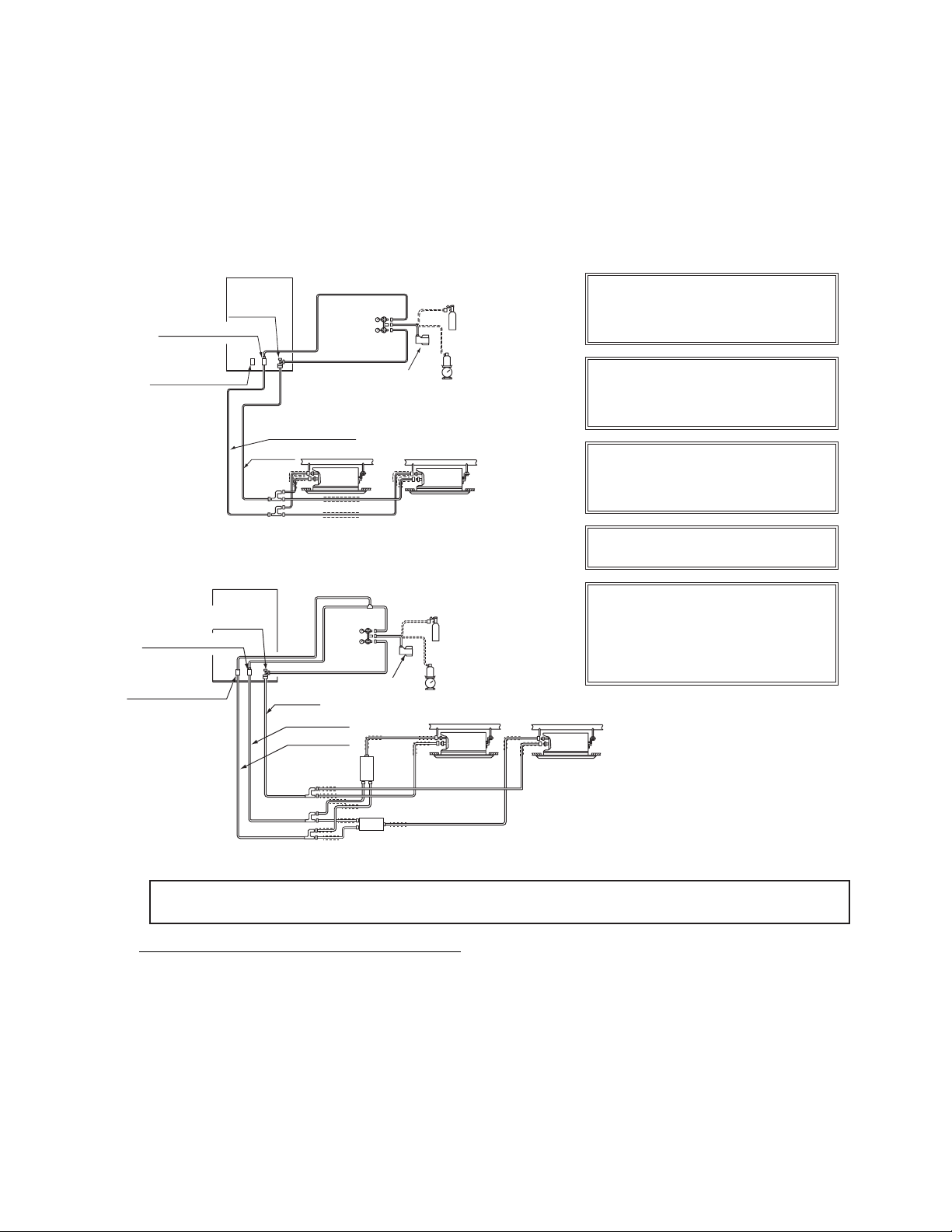
30
Charge the correct refrigerant quantity.
If not, compressor may be damaged
due to an excessive or insufficient
refrigera
nt charge.
Refrigerant charging from check joint of
gas stop valve may lead to compressor
failure. Be sure to charge refrigerant
from the check joint of liquid stop valve.
Insulate the liquid piping and gas piping
completely to avoid decreasing of
performance and dewing on the surface
of the pipe.
Insulate the flare nut and union of the
piping connection with insulation.
Check to ensure that there is no gas
leakage. If a severe refrigerant leakage
occurs, it will cause difficulty with
breathing or harmful gases would
generate when contacting with fire in the
room
Stop Valve
(Liquid Piping)
Stop Valve
(High/Low Pressure Gas Piping)
Stop Valve
(Low Pressure Gas Piping)
High/Low Pressure Gas Piping
Liquid Piping
Insulation
Switch BOX
[Cover the gas and liquid piping with insulation.]
Switch BOX
Outdoor Unit
Vacuum Pump
Siphonic Refrigerant Cylinder
(R410A)
Weigher
Nitrogen Tank
(for Nitrogen Purging during
Brazing and Air Tight Test)
Indoor Unit
Manifold Pipe
Manifold
Gauge
Insulation
Outdoor Unit
Stop Valve
Manifold
Gauge
Vacuum Pump
Nitrogen Tank
(for Nitrogen Purging during
Brazing and Air Tight Test)
Siphonic Refrigerant Cylinder
(R410A)
Weigher
High/Low
Pressure Gas Piping
Liquid Piping
(Liquid Piping
Stop Valve
(High/Low Pressure Gas Piping)
Stop Valve
(Low Pressure Gas Piping)
Manifold Pipe
Insulation
< Heat Recovery System >
Indoor Unit
(or Water Module)
[Cover the gas and liquid piping with insulation.]
(or Water Module)
Low Pressure
Gas Piping
7.3 Charging Operation
After vacuum pumping, check that the gas and liquid stop valves are completely closed.
Charge additional refrigerant (tolerance: 1.1lbs(0.5kg)) from the check joint of liquid stop valve. If the
specified refrigerant quantity can not be charged, follow the procedure below.
Fully open the stop valve for gas side
(In case of heat recovery system, fully open the stop valve for
high/low pressure and low
pressure gas pipe).
(2)
RTotally Charged Refrigerant Quantity in System (kg)
VRoom Volume for each Indoor Unit (ft
3
)
CCritical Concentration 0026lbs/ft
3
02
)
●
Special Attention Regarding Refrigerant Gas Leakage
Pay attention to the critical gas concentration to avoid accidental refrigerant gas leakage before installing
air conditioning systems.
≤
(1)
(2)
(2)
Operate the compressor in cooling mode and charge refrigerant (tolerance: 1.1lbs(0.5kg)) from the
check joint of the liquid stop valve. At this time,
the
liquid stop valve is slightly opened.
(3)
(3)
(3)
After refrigerant charge, fully open the stop valve for both liquid and gas sides.
* This value should be decided according to the each country’s regulationIS197SHR
S1Iis higher than , take the following actions:
1) Provide a gas leakage detector and fan controlled by its gas leakage detector.
2) Provide effective opening in the wall or door for ventilation to next door so that the critical gas concentrationcan
be maintained lower than the above value. (n opening 0.15% of floor surface at
the lowerpart of a door.)
8.
Test Run
Test run should be performed according to Item 8.2. And use the Table 8.1 for recording test run.
(1) Check to ensure that the refrigerant piping and transmission between outdoor unit, SW BOX, indoor units or water
modules are connected to the same refrigerant cycle. If not, it will cause an abnormal operation and a serious accident.
Check that the dip switch setting of the refrigerant cycle number and the unit number for the indoor units and water modules
apply to the system. Confirm that the dip switch setting on the printed circuit board of the indoor units, water modules and
the outdoor units are correct. Especially pay attention to the setting of lift between indoor units and outdoor unit, the
refrigerant No. and the terminal resistance.
(2) Check to ensure that the electrical resistance is more than
1MΩ, by measuring the resistance between ground and the
terminal of the electrical parts. If not, do not operate the system until the electrical leakage is located and fixed (Refer to
“Caution for Insulation Resistance” for details.). Do not impress the voltage on the terminals for transmission.
(3) Check to ensure that each wire, L1, L2, L3 is correctly connected at the power source. If incorrectly connected, the unit
will not operate and the remote control switch will indicate the alarm code “05”. In this case, check and change the phase of
the power source according to the attached sheet on the reverse side of the service cover.
(4)
Check to ensure that the switch on the main power source has been ON for more than 4 hours, to warm up the
compressor oil by the heater. When powered, the outdoor units will not operate (Stoppage Code d1-22) immediately if it is in
protection status due to low compressor oil temperature. In case of operating within 2 hours, release the protection control
as follows:
1. Supply power to the outdoor unit.
2. Wait for 30 seconds
3. Push PSW5 on the outdoor PCB more than 3 seconds in order to release the d1-22.
4. In case of using remote control switch for release, push “Air Flow” and “Auto Louver” simultaneously for 3
seconds.
WARNING
●
Do not operate the system until all the check points have been cleared.
As for the test run of indoor unit and water module, check “Installation & Maintenance Manual” attached to the indoor
unit and water module.
8.1 Before Test Run
(5) Main Unit Label
In case of the combination of basic units, attach the main unit label on a visible spot of the main unit (outdoor unit A), so
that the outdoor unit A can be identified easily. Do not attach the main label on the sub unit (outdoor unit B, C and D).
(6) Water circuit check before test run (In case of the water module is utilized in the system)
(A) Before the test run, please check again if all the water pipe construction is in the proper state.
(B) Inject water into the water module and make sure that the plate type heat exchanger is filled with cycling water;
open the water pump and exhaust valve and make sure that air in the unit and pipeline is already exhausted.
However, if leakage occurs and gas fills a room, it may cause suffocation.
Once leakage occurs, it is a must to take effective actions to make the concentration of R410A lower than
02
3
2 V
3
3
2
3
CAUTION
0
0
(C) Force the running of the water pump, read the value on the pressure gauge and confirm the action of the
flow switch to check if the water cycle system is properly installed. (Refer to installation manual of water module)
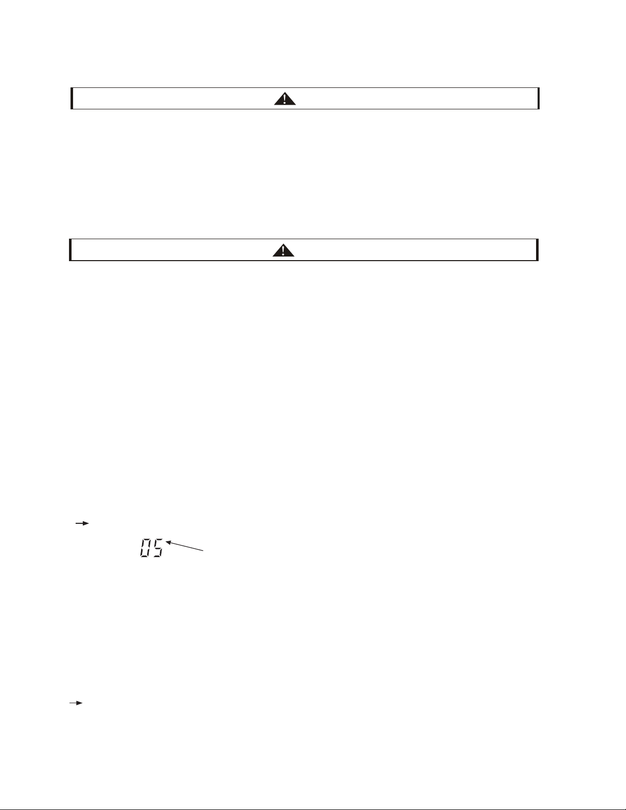
8.2 Test Run
a)
Set the “TEST RUN” mode by pressing the “MODE” and “CHECK” switch of controller simultaneously for at least 3
seconds.
"TEST RUN" is displayed on the LCD.
The total number of the indoor units connected is indicated on the LCD.
unit
Example when 5 indoor units are connected.
Regarding other optional remote control switch (wireless remote control or half-size remote control), follow
“Installation & Maintenance Manual” attached to each optional remote control switch and perform the test run.
In case that the multiple indoor units operate simultaneously controlled by one remote control switch, check the
connected number of indoor unit is indicated on LCD.
In case that the indicated number is not correct, the auto-address function is not performed correctly due to incorrect
wiring, the electric noise or etc. Turn OFF the power supply and correct the wiring after checking the following points;
(Do not repeat turning ON and OFF within 10 seconds.)
Power Supply for Indoor Unit is Not Turned ON or Incorrect Wiring.
Incorrect Connection of Connecting Cable between Indoor Units or Incorrect Connection of Controller Cable
Incorrect Setting of Rotary Switch and Dip Switch (The Setting is overlapped.) on the Indoor Units PCB.
b)
Set the operation mode by pressing “MODE” switch.
c)
Press “RUN/STOP” switch.
The operation lamp will be turned ON before the test run starts.
2-hour OFF Timer will be set automatically, and “OFF Timer” and “2HR” will be indicated LCD. Although the air flow
initial setting is “HI”, the setting can be changed.
(1) Check to ensure that the stop valves of the outdoor unit are fully opened and then start the system.
(In case of the combination module, check that the stop valves of all the connected outdoor units are fully opened.)
NOTE: Low pressure gas is used for heat recovery system only.
(2) Perform the test run of indoor units one by one sequentially and then check corresponding refrigerant piping
system and electrical wiring system. (If multiple indoor units operate simultaneously, the system can not be checked
for the system accordance.)
(3) Perform the test run according to the following procedure. Ensure that the test run is carried out without any problem.
NOTE:
In case of 2-remote control switch (main and sub), firstly perform the test run of the main remote control switch.
●
●
*
*
*
1.
NO
Confirm that field-supplied electrical components (main switch fuse, fuse-free breaker, earth leakage breakers,
wires, conduit connectors and wire terminals) have been properly selected according to the electrical data given in
the Technical Catalog of the unit and ensure that the components comply with national and local codes.
Use shielded wires (>18AWG(0.75mm
2
)) for field wiring to protect from electric noise obstacle (total length of
shielded wire shall be less than 3230.8ft.(1000m), and size of shielded wire shall comply with local codes).
Check to ensure that the terminal for power source wiring (the voltage of terminals “L1” to “L1” and of shielded
wire shall comply with local codes.). If not, some components will be damaged.
3.
2.
TICE
CAUTION
If the leakage breaker is activated, check the recommended size shown in Table 6.1.
Caution for Insulation Resistance:
If total unit insulation resistance is lower tha
n 1MΩ, the compressor insulation resistance may be low due to
retained refrigerant in the compressor. This may occur if the unit has not been used for a long period.
1. Disconnect the cables to the compressor and measure the insulation resistance of the compressor itself. If the
resistance value is ove
r 1MΩ, then insulation failure has occurred for other electrical parts.
2.
If the insulation resistance is less th
an 1MΩ, disconnect the compressor cable from the inverter PCB. Then, turn on the
main power to apply current to the crankcase heater. After applying current for more than 3 hours, measure insulation
resistance again. (Depending on the air conditions, pipe length or refrigerant conditions, it may be necessary to apply
the current for a longer period of time.) Check the insulation resistance and reconnect the compressor.
CAUTION
(D) After the initial test run, please clean the water filter and make sure that the filter mesh is clean and free of
impurities.

3
*
*
d) Depress “AUTO LOUVER” switch and check that the louver is activated normally without abnormal sound. Depress
“AUTO LOUVER” again so that the louver will stop. If there is abnormal sound, remove the panel and adjust the fitting
condition of connection parts in the panel corner cove. Ensure that the panel is mounted correctly to the unit body,
otherwise the panel may be deformed.
e) The temperature control will be invalid though the protection device will be activated during the test run. If alarm
occurs, find out the cause of abnormality according to Technical Catalog. And again perform the test run after solving
the problems.
f) According to the label “Checking of Outdoor Unit by 7-segment Display on PCB1” attached to the rear side of the front
cover of the outdoor unit, inspect temperature, pressure, operation frequency, and connected indoor unit numbers by
the 7-segment displays.
g) To end the test run, wait for 2 hours or push “RUN/STOP” switch again.
●
Check the operation range according to page I.
Do not touch any of the parts by hand at the discharge side, since the compressor chamber and the pipes at
the discharge side are heated to above 194°F(90°C).
DO NOT PUSH THE BUTTON OF THE MAGNETIC SWITCH(ES). It will cause a serious accident.
Do not touch any electrical components for at least 10 minutes after turning OFF the main switch.
Check that the refrigerant piping setting and electrical wiring setting are for the same system, by operating the
indoor unit one by one.
●
●

4
WB
Inlet: DB
Outlet:
DB
psi(MPa)
psi(MPa)
V
V, L
1
-L
3
V, L
2
-L
3
V
V
V
V
:
m
kW
A
1
n
-
=
Table 8.1 Test Run and Maintenance Record
COMPRESSOR MFG. No.
DATE:
1.
Is the rotation direction of the indoor fan correct?
2.
Is the rotation direction of the outdoor fan correct?
3.
Are there any abnormal compressor sounds?
4.
Has the unit been operated at least twenty (20) minutes?
5.
Check Room Temperature:
6.
Check Outdoor Ambient Temperature:
7.
Check Refrigerant Temperature:
Liquid Temperature:
Discharge Gas Temperature:
8.
Check Pressure:
Discharge Pressure:
Suction Pressure:
9.
Check Voltage:
Rated Voltage:
Operating
Voltage:
Starting Voltage:
Phase imbalance
10.
Check Compressor Input Running Current:
Input:
Running Current:
11.
Is the refrigerant charge adequate?
12.
Do the operation control devices operate correctly?
13.
Do the safety devices operate correctly?
16.
Are all cabinet panels fixed?
17.
Are all cabinet panels free from rattles?
18.
Is the filter clean?
19.
Is the heat exchanger clean?
20.
Are the stop valves open?
21.
Does the drain water flow smoothly from the drain pipe?
14.
Has the unit been checked for refrigerant leakage?
15.
Is the unit clean inside and outside?
22.
Do the components of the system change and replace?
MODEL:
SERIAL. No.
CUSTOMER'S NAME AND ADDRESS:
THE RESULT OF ALL PERIODIC ROUTINE TESTS:
L
1
-L
2
*Check the installation manual of water module for additional items should be recorded in case of water module is utilized.
Inlet:
Outlet:
Inlet:
Outlet:
No.1 DB /WB
o
F(
o
C)
No.2 DB /WB
o
F(
o
C)
No.3 DB /WB
o
F(
o
C)
No.4 DB /WB
o
F(
o
C)
DB /WB
o
F(
o
C)
DB /WB
o
F(
o
C)
DB /WB
o
F(
o
C)
DB /WB
o
F(
o
C)
No.5 DB /WB
o
F(
o
C)
No.6 DB /WB
o
F(
o
C)
No.7 DB /WB
o
F(
o
C)
No.8 DB /WB
o
F(
o
C)
DB /WB
o
F(
o
C)
DB /WB
o
F(
o
C)
DB /WB
o
F(
o
C)
DB /WB
o
F(
o
C)
WB
o
F(
o
C)
o
F(
o
C)
o
F(
o
C)
o
F(
o
C)
o
F(
o
C)
o
F(
o
C)


082022
V01
TC