Loading ...
Loading ...
Loading ...
MCD425A/W, R425A/W, MFD425A/W, P425A/W Ice Machines 13
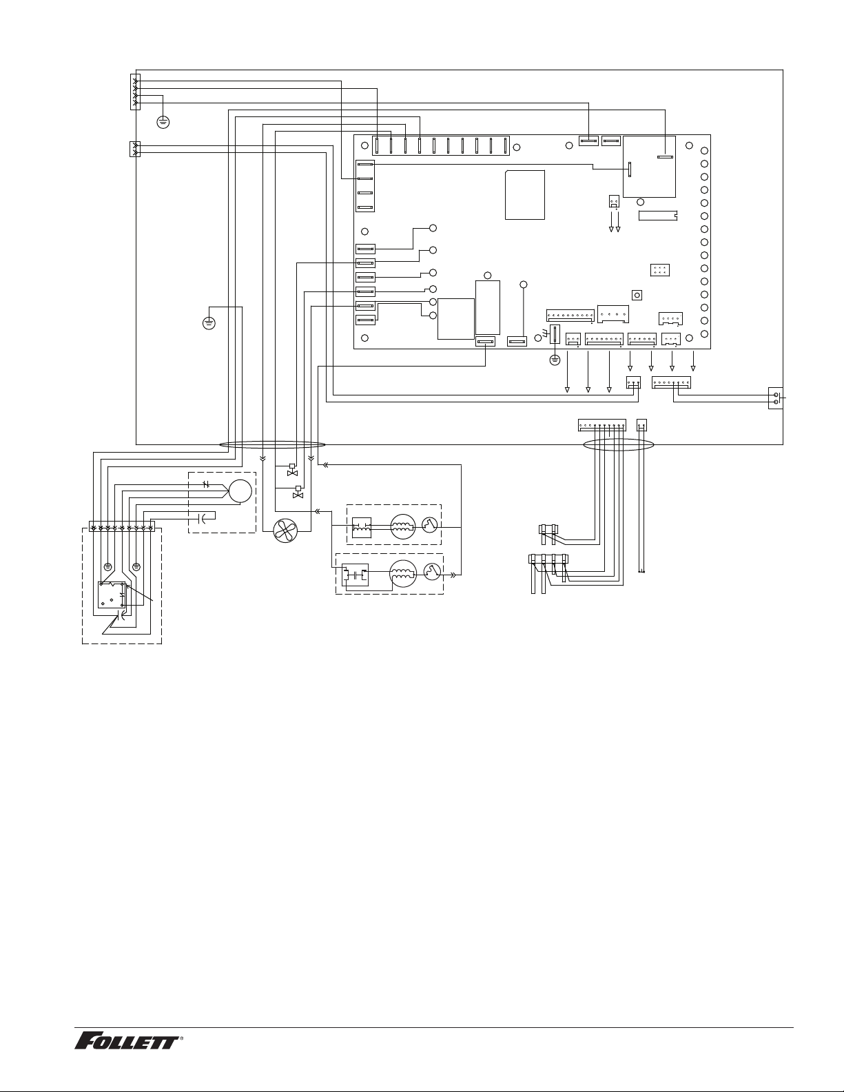
Electrical control system schematic
WATER LEVELS
P17
BIN
P12
CLEAN SAFE
P11
POWER
LOW BIN
MAKING ICE
SLEEP CYCLE
TIME DELAY
LOW WATER
MAINTENANCE
SERVICE
HI AMPS
HI PRESSURE
CLEANER FULL
RESERVOIR
WATER SENSOR
MAINT.
CLEAN
HI PRS
P14
HIGH
PRESS
P
A B C D
BLACK
YELLOW
ORANGE
RED
GRN #17
BLACK #51
BLACK #23
BIN
CONTACT
CLOSURE
L1
L2/N
DISP
GND
BLACK #23
GRN-YEL #24
WHITE #25
BLACK #26
WHITE
BLUE
SPLIT-PHASE
START
RELAY
3
4
2
YELLOW
BLACK
T.O.L.
START
RUN
FAN
FEED VALVE
DRAIN VALVE
RED #16
WHITE #121
WHITE #13
BROWN #14
BLACK #122
BLUE #07
BLACK #51
WHITE #52
COMP.
R
C
S
O.L.
C2 START
1 2 3 4 5 6 7 8 9
GREEN #53
COMPRESSOR
COMPRESSOR
ELECTRICAL
BOX
BLACK #51
WHITE #52
GREEN #53
RED #54
ORANGE #55
BLACK #56
GREEN #57
BLACK #58
BLACK #59
6
4
1
2
5
BLACK #61
WHITE #62
GREEN #63
WHITE #64
BLACK #65
BLACK #66
GREEN #67
BLACK #68
BLACK #69
C1 RUN
BLACK #66
BLACK #69
BLACK #71
#15
#04
#05
WHITE
DRAIN CLOG
SENSOR
BLACK
VIOLET
DRAIN CLOG
MODEL SELECT
SERIAL COMM
COMPRESSOR
AUGER
WATER LEVELS
HI PRS
BIN RS485
RS485 UI
CURRENT SENS
RESET
PROGRAM
P5
ICE AUX WATER AUX
D9
D8
D7
D6
D5
D4
D37
D3
D2
D18
D16
D15
D14
D13
D12
D11
D10
D1
T1
P18
P11
P13
P17
P12
P14
P16
P15
P4
T2
S1
S2
K1
P7
P8
P10
K3
1
2
6
5
P9
L1 L1L1
N N N N N N N N N
P2
P1
P21
P20
P19
P3
BLACK #01
P6
P22
D19D22D21D20
D17
D48
BLACK
BLACK
BLUE
OR
CAPACITOR
T.O.L.
START
RUN
BLACK
YELLOW
PSC MOTOR
Electrical control system operation
The P425A/W, MCD425A/W_S and R425A/W wiring diagrams which follow illustrate the circuitry of Follett ice
machines used with ice dispensers. Both normal operation of the ice machine (Stages 1–6) and non-normal
diagnostic sequences showing torque-out (Stages 7–10) for use in troubleshooting ice machine problems are
shown.
Circuitry notes
When the ice machine is used with a dispenser it receives power from the main power supply. Disconnect the
power source before performing service. When performing electrical service, always use a meter to determine
whether or not the components being serviced are energized.
§ High pressure cutout opens at 425 PSI and closes at 287 PSI (auto reset).
§ The bin signal input to the control board in the 425A/W ice machine must only be initiated by contact closure. Do
not supply power. To run the ice machine in the workshop, use the bin signal jumper (P/N 01069095).
Loading ...
Loading ...
Loading ...