Loading ...
Loading ...
Loading ...
Maintenance
32 Owner’s Manual for 60 Hz Air-Cooled Generators
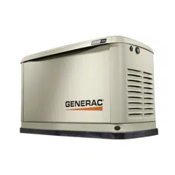
5. See Figure 4-10. Inspect battery posts and cables
for tightness and corrosion. Tighten and clean as
necess
ary.
–
+
001832
Figure 4-10. Battery Cables
6. Unsealed batteries only: Completely
disconnect
battery, removing negative battery cable first.
Check battery fluid level and, if necessary, fill with
distilled water only. DO NOT use tap water. Have
an IASD or a qualified service technician verify
state of charge and condition.
7. Con
nect positive battery cable, then negative bat-
tery cable.
8. Con
nect battery charger cable.
9. Install intake side
panel, and install 7.5 A fuse.
10. Pre
ss AUTO button on controller.
11. Install fr
ont panel and close generator lid.
Cleaning the Sediment Trap
The sediment trap removes contaminants (moisture and
fine particles) from gaseous fuels before they enter the
fuel regulator. Accumulated moisture and particles must
be emptied from the sediment trap per local codes and
guidelines.
Proceed as follows to c
lean sediment trap:
1. Remove intake side panel.
See Intake Side Panel
Removal.
2. T
urn generator fuel supply OFF.
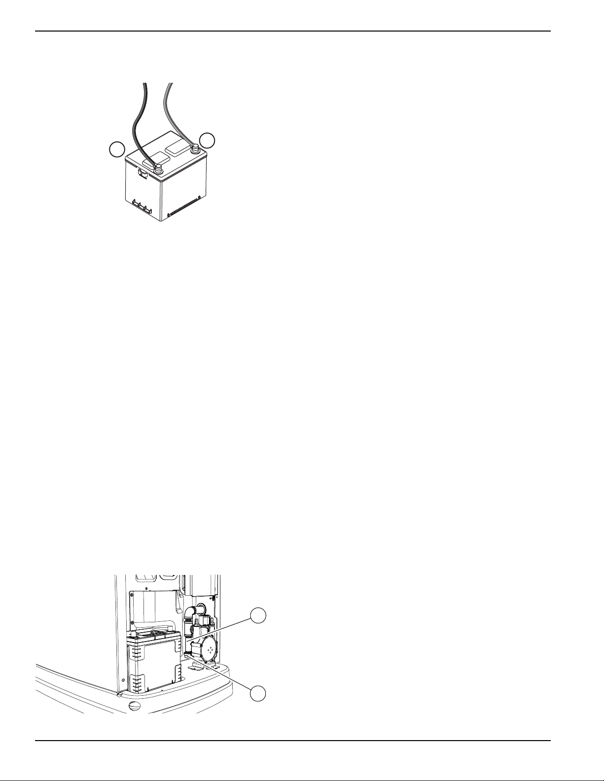
3. See Figure 4-11. Unscrew and remove cap (A).
Figure 4-11. Cleaning the Sediment Trap
4. Use
a clean-out tool (not provided) to remove
accumulated moisture and particles from cap and
body (B).
5. Wipe
inside of each component with a clean, dry,
lint-free cloth.
6. Sea
l threads of cap with appropriate sealing com-
pound. Install cap and hand-tighten.
7. T
ighten cap with an appropriately sized pipe
wrench. DO NOT overtighten.
8. T
urn generator fuel supply ON. Inspect for leaks by
spraying all connection points with a non-corrosive
gas leak detection fluid. Solution should not be
blown away or form bubbles.
9. Insta
ll intake side panel.
Post Maintenance Checks
Proceed as follows to perform post maintenance checks:
1. Per
form required maintenance procedure(s).
2. Insta
ll intake side panel and front panel if removed.
(See Intake Side Panel Removal and Front
Access Panel Removal.)
3. Insta
ll 7.5A fuse in control panel.
4. Complete Install
Wizard information.
5. Pre
ss AUTO button on control panel. Allow unit to
run for one minute with no load (if running during a
utility outage).
6. Se
t generator MLCB (generator disconnect) to ON
(CLOSED).
7. Set utility MLC
B to ON (CLOSED).
The system is now in AUTO.
NOTE: If correc
t utility is present at this time, generator
will perform its usual shutdown process.
001821
A
B
Loading ...
Loading ...
Loading ...