Loading ...
Loading ...
Loading ...
9
English
6. Confirm the direction of bit rotation
(Fig. 2)
The bit rotates clockwise (viewed from
the rear side) when the reversing switch
lever is set to the “R” side position.
When the lever is set to the “L” side po-
sition, the bit rotates counterclockwise
and can be used to loosen and remove
screws.
CAUTION:
Never change the bit rotating direction
while operating the Screw Driver. Turn
the main switch off before changing
the rotating direction, otherwise, burn-
ing of the motor will result.
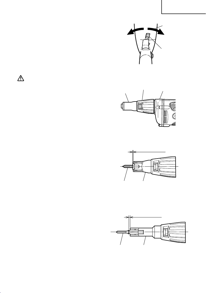
7. Adjusting the tightening depth
(Fig. 3)
The tightening depth can be adjusted
by turning locator right and left with
click feeling.
(1) For hex-head screws (Fig. 4)
Mount a hex-head screw on the hex-
socket and set the distance between the
sub-stopper end and the screw head
neck to 0.04” – 0.06” (1 – 1.5 mm).
(2) For drywall screws (Fig. 5)
Mount a drywall screw on the bit, and
set the distance between the sub-stop-
per end and the screw head to 0.06” –
0.07” (1.5 – 2 mm).
(3) For cross-recessed self-drilling screws
(Fig. 6)
Mount a self-drilling screw on the bit,
and set the distance between the sub-
stopper end and the screw head bot-
tom to 0.04” – 0.06” (1 – 1.5 mm).
Fig. 2
R side
Lever
Fig. 4
0.04" – 0.06"
(1 – 1.5 mm)
Hex. head
screw
Sub-Stopper (B)
Fig. 5
0.06" – 0.07"
(1.5 – 2 mm)
Drywall screw
Sub-Stopper (F)
Fig. 3
Sub
Stopper (B)
Locator
Gear cover
01Eng_W6VM_US.p65 10/10/12, 9:329
Loading ...
Loading ...
Loading ...