Loading ...
Loading ...
Loading ...
31-5000573 Rev. 2 21
ENGLISH
INSTALLATION INSTRUCTIONS
Allowing Piping Length and Drop Between Indoor and Outdoor (cont.)
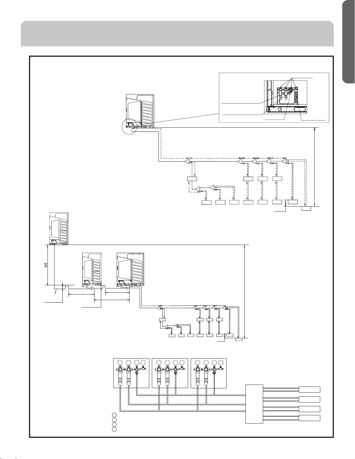
2. Allowable piping length and drop
between indoor and outdoor unit.
L5
L6
L7 L8
L9
L10
L11
L12 L13
L14
L15
L16 L18
L20
L17 L19
L21
L22
V2
V1
A
BCDE
F
H2
H3
H
G
V3 V4
Detail view for stop valve of HR unit
Service port
Charge value
Liquid pipe
High pressure gas pipe
Low pressure gas pipe
Outdoor is only one
Outdoor 3
1
1 12 2 23 3 34 4 4
AAA
A
BBB
B
CCC
C
1 ---- High pressure gas pipe stop valve
2 ---- Low pressure pipe stop valve
3 ---- Liquid pipe stop valve
4 ---- Charge valve
A ---- High pressure gas pipe
B ---- Low pressure pipe
C ---- Liquid pipe
The connection sketch of stop valves and pipes
Connection
Kit
Liquid pipe
Liquid pipe
Liquid pipe
Liquid pipe
Gas pipe
Gas pipe
Gas pipe
Gas pipe
Indoor Unit
Indoor Unit
Indoor Unit
Indoor Unit
When the distance between outdoors(L1, L3) is over 6-9/16 ft., the oil trap must be set (upright
projecting pipe, 7-7/8 in. high), as the figure :
The outdoor is more than one unit.
Outdoor 1
Outdoor 2 Outdoor 3
A
B
C
D
EF G
L1
L2
L3
L4
L5
L6 L7 L8 L9
L10
L11
L12 L13
L14
L15
L16 L18 L20
L22
H2
H3
H
L17 L19
L21
V1 V2 V3 V4
L3<32-13/16 ft.
L1+L3<32-13/16 ft.
L2+L3<32-13/16 ft.
Note:
V1---V4: VP unit
A---F: indoors (coling / heating selection possible)
G---H: indoors (cooling only)
Below 6-9/16 ft.
Below 6-9/16 ft.
Over 7-7/8 in.
Over 7-7/8 in.
Loading ...
Loading ...
Loading ...