SYJS-04-2017REV.B Edition: 2017-04
FlexFit PRO

FlexFit PRO
CONTENTS
Part 1 General Information .......................................................................................................................................1
1. Lineup ..................................................................................................................................................................2
2. Features ..............................................................................................................................................................3
91.............................................................................................................. epyT ettessaC yaW-4--stinU roodnI 3 traP
02.............................................................................................................................................................. serutaeF.1
....................................................................................................................................................21
3. Dimensions ........................................................................................................................................................24
............................................................................................................................................. 25
5. Air Velocity and Temperatures ...........................................................................................................................26
6. Installation .........................................................................................................................................................30
Part 4 Indoor Units-Medium ESP Duct Type .........................................................................................................36
1. Features ............................................................................................................................................................37
....................................................................................................................................................38
3. Dimensions ........................................................................................................................................................41
.............................................................................................................................................43
5. Instalaltion .........................................................................................................................................................45
Part 5 Outdoor Units ...............................................................................................................................................51
....................................................................................................................................................50
2. Dimensions ........................................................................................................................................................53
3. Piping ...............................................................................................................................................................55
.............................................................................................................................................56
5. Installation .........................................................................................................................................................58
Part 6 Controls and Troubleshooting ....................................................................................................................63
1. Indoor Unit PCB ................................................................................................................................................64
2. Dip Switches ......................................................................................................................................................65
3. Outdoor Unit PCB ..............................................................................................................................................68
4. Error Codes .......................................................................................................................................................70
5. Error Code Analysis ...........................................................................................................................................83
6. Functions ...........................................................................................................................................................92
7. Controllers ......................................................................................................................................................104
Part 7 Appendix
1. Sensor Characteristics .................................................................................................................................104
Part 2 Indoor Unit Technical Overview - Wall Mount ..................................................................................
.................. 5
1.Components......................................................................................................................................................... 5
2.Testing.................................................................................................................................................................13
3.Error Codes.........................................................................................................................................................15

1
FlexFit Pro
Part 1 General Information
Part 1 General Information .......................................................................................................................................1
1. Lineup ..................................................................................................................................................................2
2. Features ..............................................................................................................................................................3
3.Indoor Unit Technical Overview - Wall Mount .................................................................................................... 5
4.Components......................................................................................................................................................... 5
5.Testing.................................................................................................................................................................13
6.Error Codes.........................................................................................................................................................15
2
FlexFit Pro
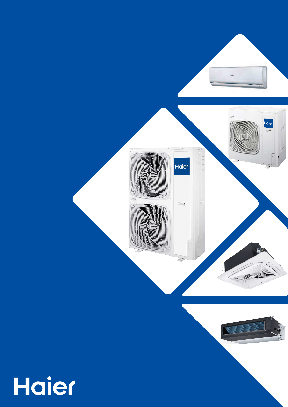
1. Line up
Model Apperance
Indoor unit
4-Way Cassette
AL24LP2VHA
AL36LP2VHA
AL48LP2VHA
Medium Esp Duct
AM24LP2VHA
AM36LP2VHA
AM48LP2VHA
Model Apperance
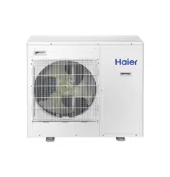
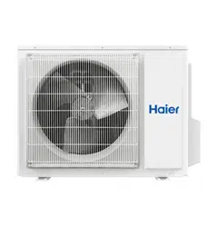
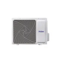
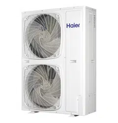
Outdoor unit
1U24LP2VHA
1U36LP2VHA
1U48LP2VHA
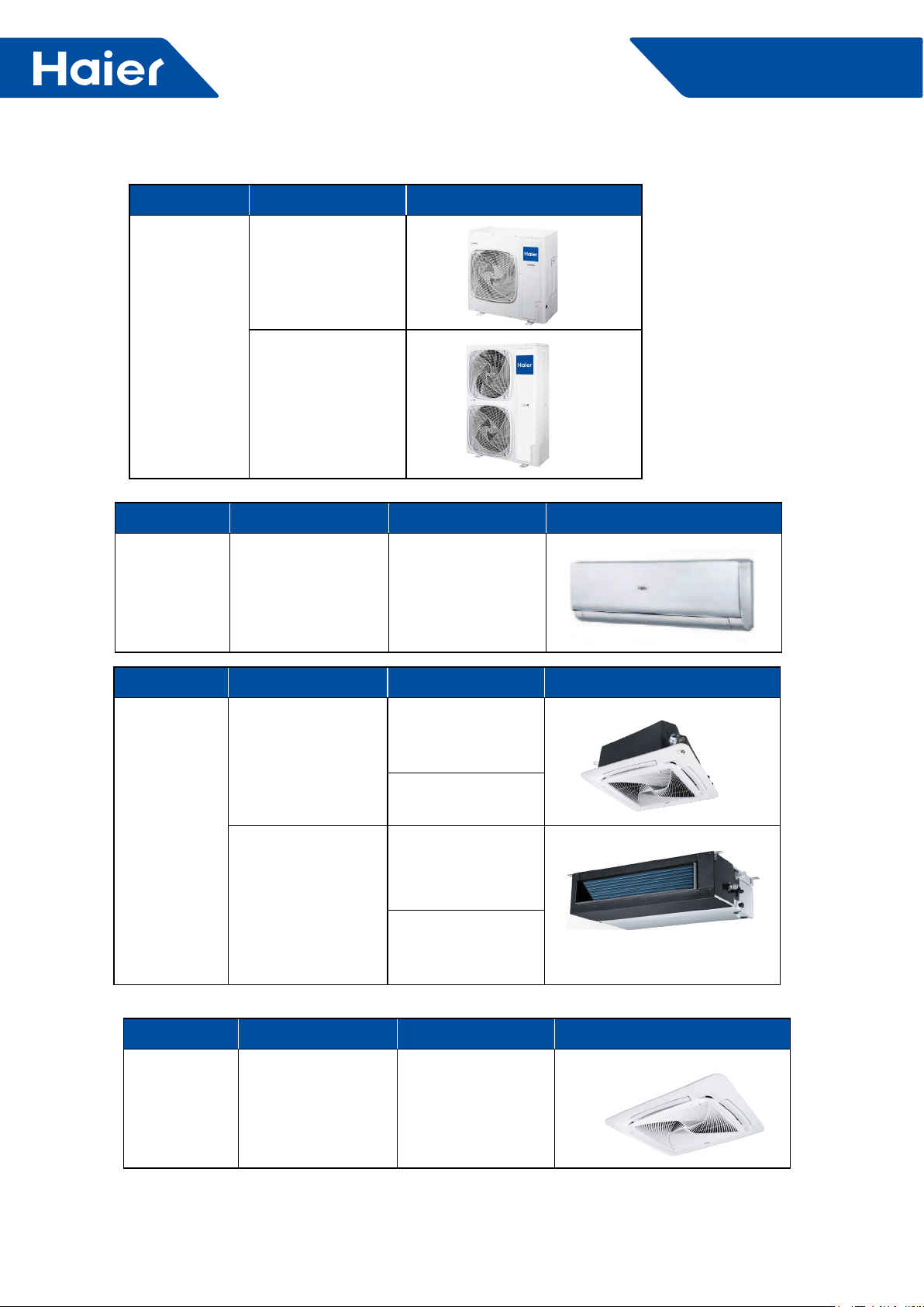
Model Apperance
Panel 4-Way Cassette PB-950KB
Model Apperance
Indoor unit High-Wall AW24LP2VHA
AW36LP2VHA
3
FlexFit Pro
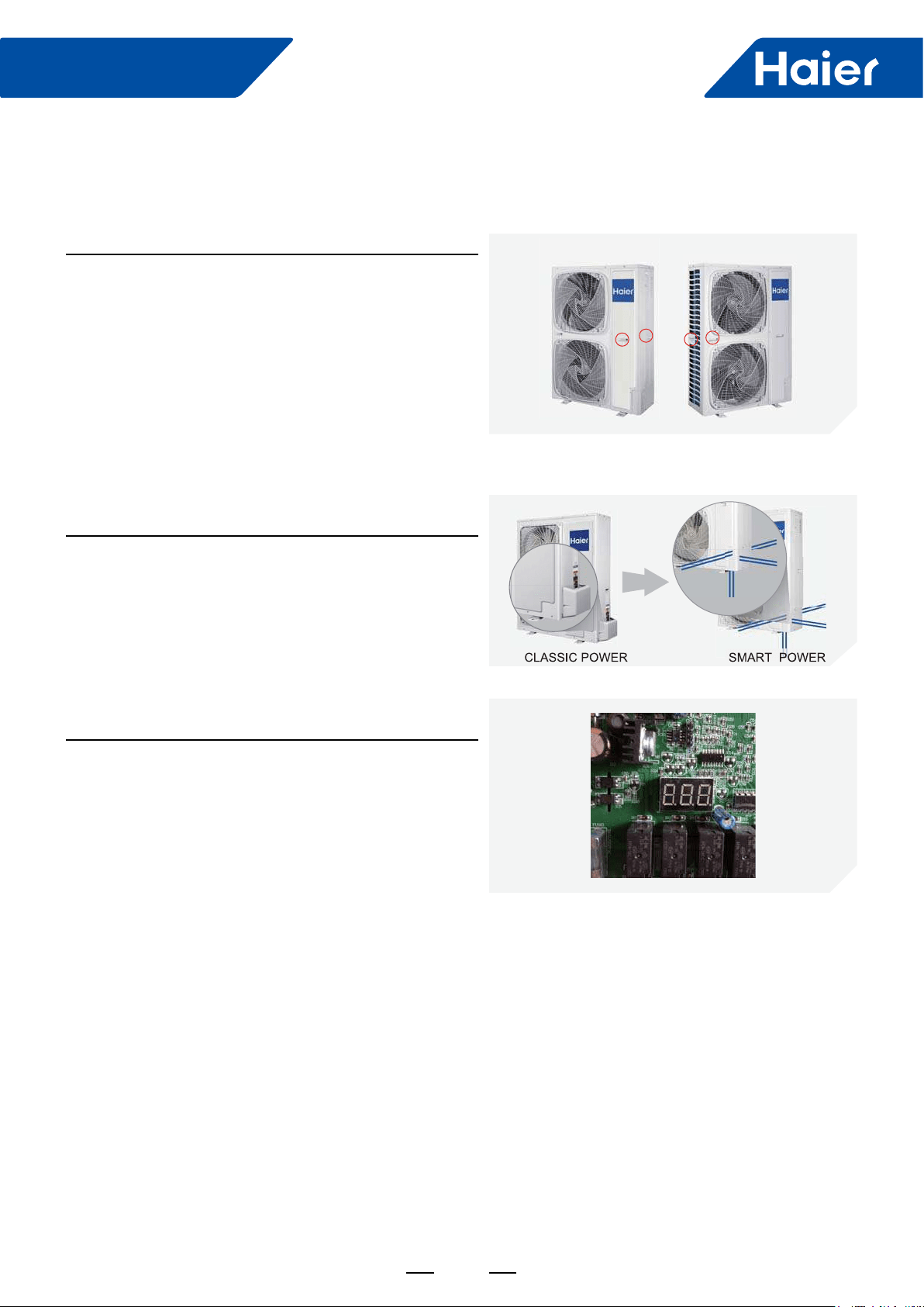
Stylish Design
Built-in service valves mean a clean looking exterior and
allow for a 4-direction line set connection.
Easy Installation
"888" Digital Display
Easy for technicians to check running parameters and error
codes.
2. Features
Double side 4 handles
Two handles on each side make installation a breeze.
4
FlexFit Pro
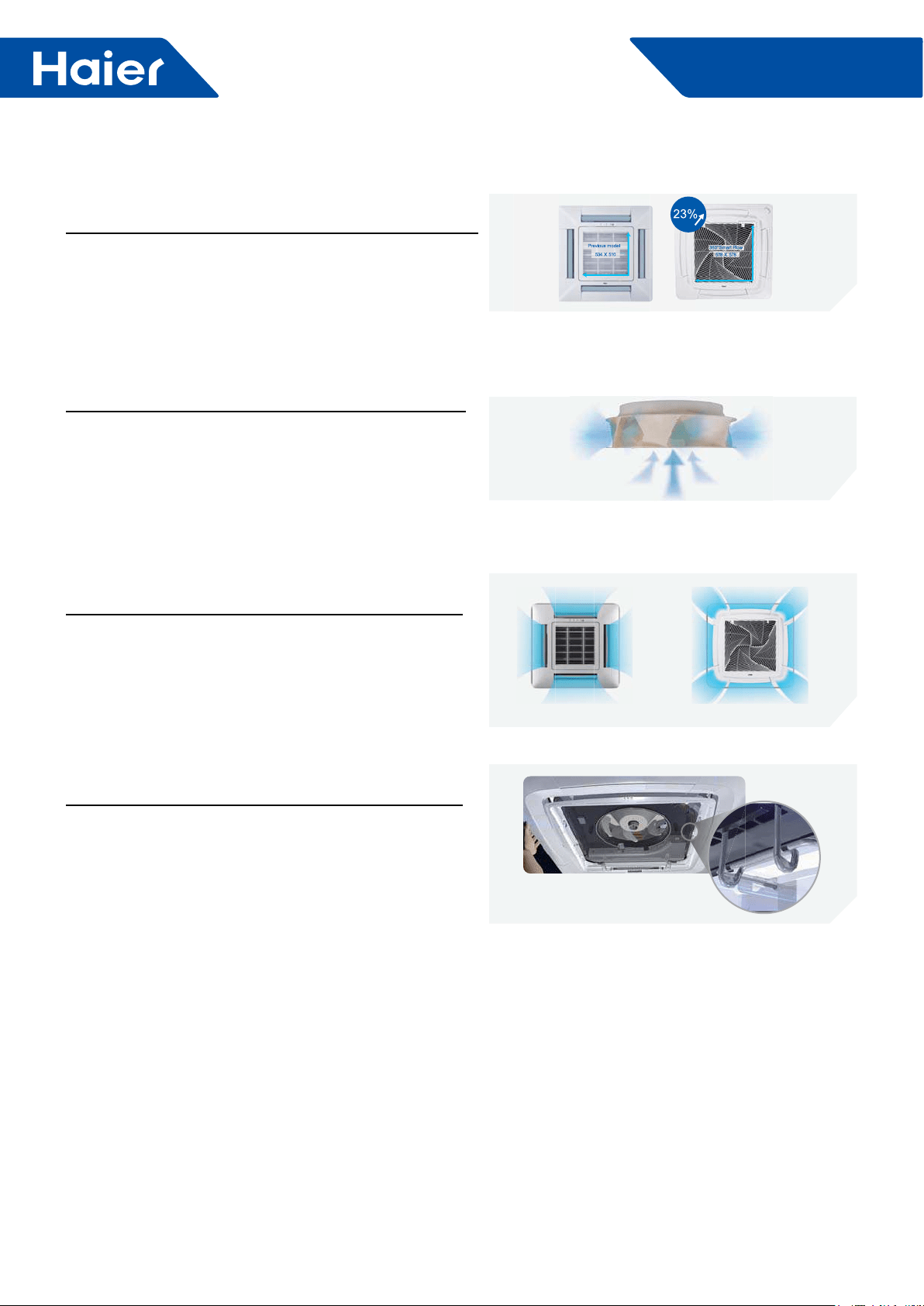
Comfort
360° air supply
360 degree air pattern eliminates dead air spots and
Easy Installation
Convenient Grille Clip
Holds grille in place during installation to save time and
effort.
4 way air ow Unique 360° air ow design
New Fan
Larger size and aerodynamic design mean low sound and
less resistance.
Low Sound Level
Super big inlet grille
Inlet grille is 23% larger than conventional models, which
means quiet operation and lower air speed.
I
5
FlexFit Pro
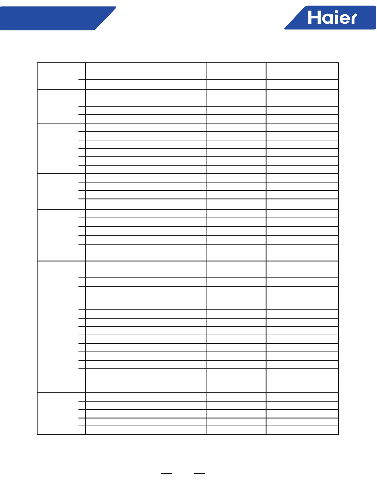
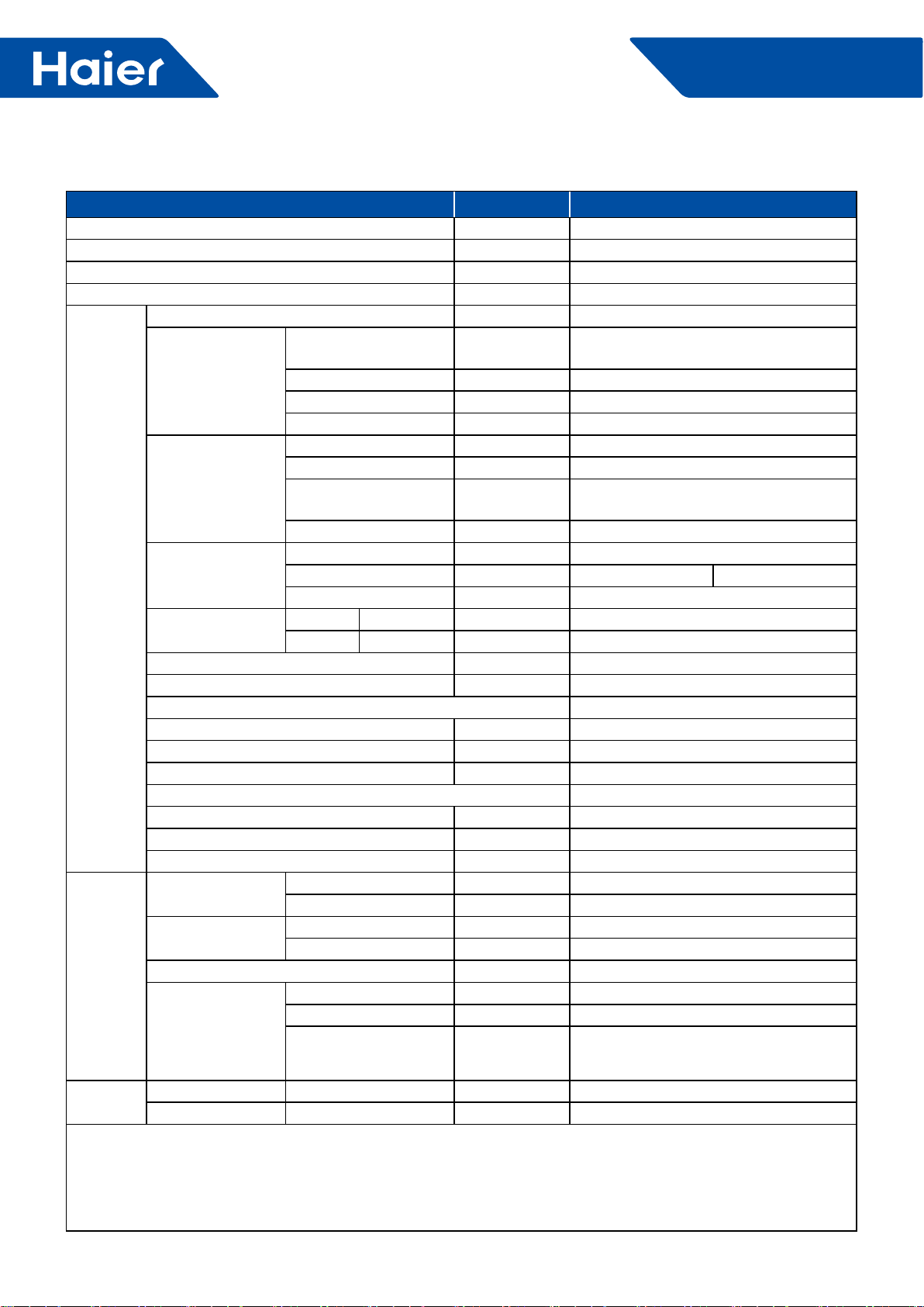
System Type Wall Mount Wall Mount
Outdoor
1U24LP2VHA 1U36LP2VHA
Indoor AW24LP2VH* AW36LP2VH*
Voltage, Cycle, Phase
V/Hz/-
208-230/60/1 208-230/60/1
Wire Size between ID and OD 14/4 AWG Stranded 14/4 AWG Stranded
Maximum Fuse Size A25 30
Minimum Circuit Amp A21 26
Rated Capacity Btu/hr 24000 35000
Capacity Range Btu/hr 6800-30700 8500-37500
Rated Power Input W2,182 3,500
SEER
17.0 17.0
EER 11.0 10.0
Moisture Removal Pt./h 4.10 5.1
Rate Heating Capacity 47°F
Btu/hr
27000 37000
Heating Capacity Range Btu/hr 6800-34100 8500-41000
Rated Power Input W2700 3700
HSPF 10.0 10.0
Outdoor Noise Level dB 47 52
Dimension: Height in (mm) 38 (965) 38 (965)
Dimension: Width in (mm) 37 3/8(950) 37 3/8(950)
Dimension: Depth in (mm) 14 5/8(370) 14 5/8(370)
Weight (Ship/Net)- lbs (kg) 202.8/ 176.4 (92/80) 207.2/180.7 (94/82)
Indoor Sound Level dB
(Turbo/High/Med/Low/Quiet) 49/47/42/36/34 50/48/44/38/36
Airflow (Turbo/High/Med/Low/Quiet)
CFM
710/650/560/440/410 720/660/570/450/420
Dimension: Height in (mm) 13 1/4(336) 14 3/8(365)
Dimension: Width in (mm) 43 7/8(1115) 51 13/16(1316)
Dimension: Depth
in (mm)
9 9/16(243) 10 7/8(275)
Max. External Static Pressure in.W.G(Pa) NA NA
Drainpipe Size O.D. in NA NA
Internal Condensate Pump NA NA
Max. Drain-Lift height in(mm) NA NA
Grill Model NA NA
Grill Dimension: H×W×D in (mm) NA NA
Weight (Ship/Net)- lbs (kg) 45.4/37.5(20.6/17) 55.1/46.3(25.5/21)
Connections Flare Flare
Liquid/Suction O.D. in 3/8 5/8 3/8 5/8
Factory Charge Oz 88.2 88.2
Maximum Line Length
Ft / m
165/50 165/50
Maximum Height Ft / m 100/30 100/30
Refrigerate Line
Model Name and
Operation Range
Power Supply
Cooling
Heating
Outdoor Unit
Indoor Unit
FlexFit Pro
6
AW24LP2VHA
AW36LP2VHA

10
11
12
13
14
15
16
17
18

19
FlexFit Pro
Part 3 Indoor Units--4-Way Cassette Type
1. Features ..............................................................................................................................................................20
......................................................................................................................................................21
3. Dimensions ........................................................................................................................................................24
.............................................................................................................................................25
5. Air Velocity and Temperatures ...........................................................................................................................26
6. Installation .........................................................................................................................................................30

20
FlexFit Pro
1. Feature
Stylish Grille Design
"Spiral" panel
Spiral panel concept is a Haier exclusive.
Full-closing Panel
Flap is hidden during the off cycle for an attractive look and
low energy loss.
ABS Panels
Bright white color won't yellow over time.
New designed fan
This is already in the OD section. Eliminate or change
picture and text.
Individual Flaps
Control all four independently to provide maximum comfort
and air movement.
Comfort solution
Adiustable
Comrner installation solution

21
FlexFit Pro
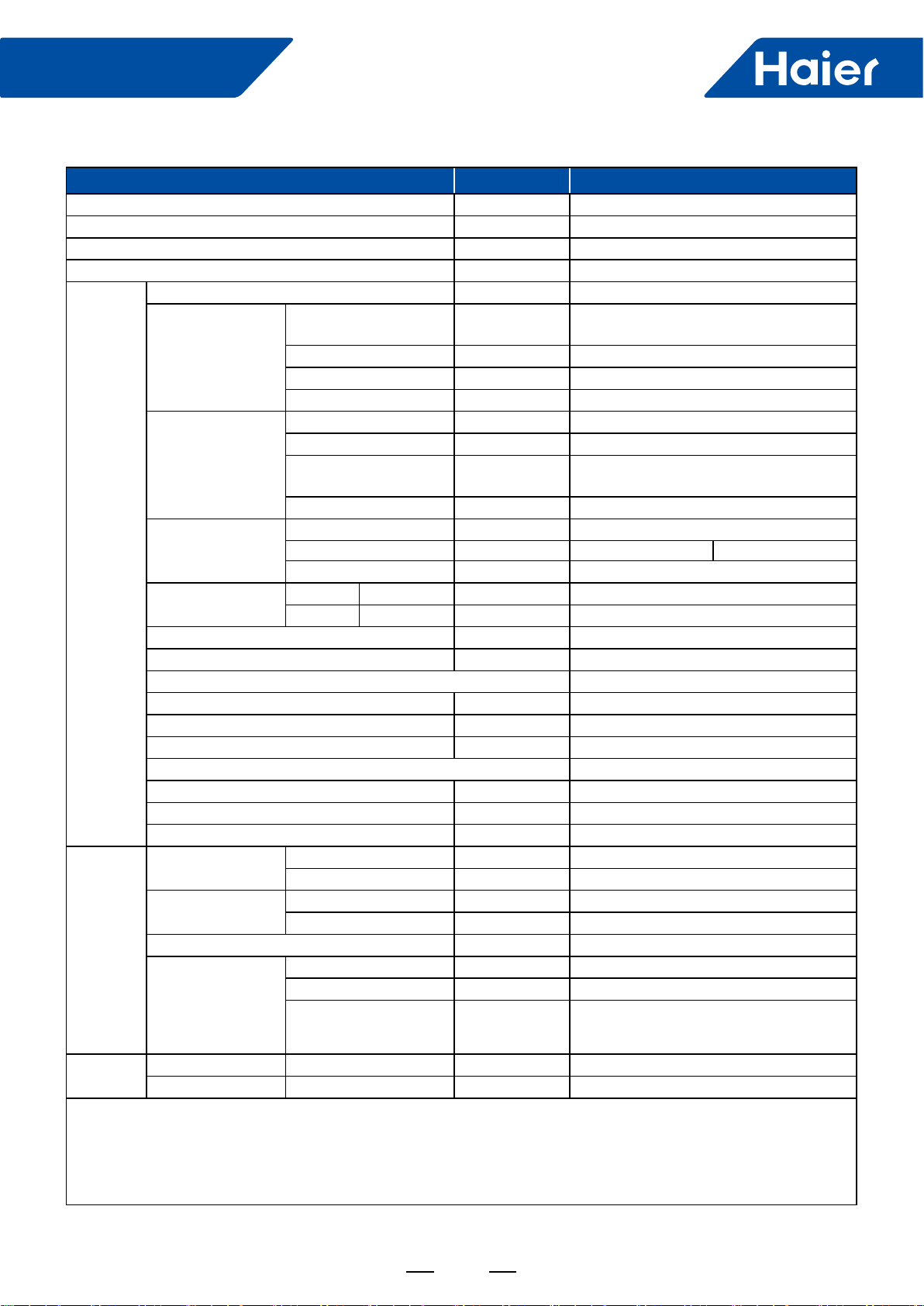
2. Specications
Model Name
System AL24LP
Outdoor 1U24LP2VHA
Indoor AL24LP2VH*
Cooling
Rated Capacity Btu/hr 24000
Capacity Range Btu/hr 6800-27000
Rated Power Input W2,087
SEER 17
EER 11.5
Moisture Removal Pt./h 5.1
Heating
Rate Heating Capacity 47°F Btu/hr 27300
Heating Capacity Range Btu/hr 6800-30500
Rated Power Input W2,281
HSPF 10
Operating Range Cooling °F(°C) 0~115F(-18-46C)*
Heating °F(°C) -4°F~75°F (-20-24℃)
Power Supply Voltage, Cycle, Phase V/Hz/- 208-230/60/1
Outdoor Unit
Compressor Type DC Inverter Driven Rotary
Maximum Fuse Size A 25.0
Minimum Circuit Amp A 21.0
Outdoor Fan Speed RPM 750/700/650/600/500/400/300
Outdoor Noise Level dB 47
Dimension: Height in (mm) 38 (965)
Dimension: Width in (mm) 37 3/8(950)
Dimension: Depth in (mm) 14 5/8(370)
Weight (Ship/Net)- lbs (kg) 202.8/ 176.4 (92/80)
Indoor Unit
Fan Speed Stages 4 + Auto
Airow (Turbo/High/Med/Low/Quiet) CFM 740/630/480/400
Motor Speed (Turbo/High/Med/Low/Quiet) RPM 500/400/300/250
Indoor Sound Level dB (Turbo/High/Med/Low/Quiet) 36/33/29/26
Dimension: Height in (mm) 9 5/8 (246)
Dimension: Width in (mm) 33 1/8(840)
Dimension: Depth in (mm) 33 1/8(840)
Max. External Static Pressure in.W.G(Pa) NA
Drainpipe Size O.D. in 1 1/4
Internal Condensate Pump Standard
Max. Drain-Lift height in(mm) 39 3/8 (1000)
Grill Model PB-950KB
Grill Dimension: Height in (mm) 2 (50)
Grill Dimension: Width in (mm) 37 3/8 (950)
Grill Dimension: Depth in (mm) 37 3/8 (950)
Weight (Ship/Net)- lbs (kg) 79.4/68.3 (36/31)
Refrigerant Lines
Connections Flare
Liquid O.D. in 3/8
Suction O.D. in 5/8
Factory Charge Oz 88.2
Maximum Line Length Ft / m 165/50
Maximum Height Ft / m 100/30
22
FlexFit Pro
Model Name
System AL36LP
Outdoor 1U36LP2VHA
Indoor AL36LP2VH*
Cooling
Rated Capacity Btu/hr 35000
Capacity Range Btu/hr 8500-37500
Rated Power Input W3,500
SEER 17
EER 10
Moisture Removal Pt./h 6.3
Heating
Rate Heating Capacity 47°F Btu/hr 36500
Heating Capacity Range Btu/hr 8500-38500
Rated Power Input W3,253
HSPF 10.3
Operating Range Cooling °F(°C) 0~115F(-18-46C)*
Heating °F(°C) -4°F~75°F (-20-24℃)
Power Supply Voltage, Cycle, Phase V/Hz/- 208-230/60/1
Outdoor Unit
Compressor Type DC Inverter Driven Rotary
Maximum Fuse Size A 30
Minimum Circuit Amp A 26.0
Outdoor Fan Speed RPM 750/700/650/600/500/400/300
Outdoor Noise Level dB 52
Dimension: Height in (mm) 38 (965)
Dimension: Width in (mm) 37 3/8(950)
Dimension: Depth in (mm) 14 5/8(370)
Weight (Ship/Net)- lbs (kg) 207.2/180.7 (94/82)
Indoor Unit
Fan Speed Stages 4 + Auto
Airow (Turbo/High/Med/Low/Quiet) CFM 990/900/776/700
Motor Speed (Turbo/High/Med/Low/Quiet) RPM 650/550/450/400
Indoor Sound Level dB (Turbo/High/Med/Low/Quiet) 45/42/38/34
Dimension: Height in (mm) 9 5/8 (246)
Dimension: Width in (mm) 33 1/8(840)
Dimension: Depth in (mm) 33 1/8(840)
Max. External Static Pressure in.W.G(Pa) NA
Drainpipe Size O.D. in 1 1/4
Internal Condensate Pump Standard
Max. Drain-Lift height in(mm) 39 3/8 (1000)
Grill Model PB-950KB
Grill Dimension: Height in (mm) 2 (50)
Grill Dimension: Width in (mm) 37 3/8 (950)
Grill Dimension: Depth in (mm) 37 3/8 (950)
Weight (Ship/Net)- lbs (kg) 79.4/68.3 (36/31)
Refrigerant Lines
Connections Flare
Liquid O.D. in 3/8
Suction O.D. in 5/8
Factory Charge Oz 88.2
Maximum Line Length Ft / m 165/50
Maximum Height Ft / m 100/30
23
FlexFit Pro
Model Name
System AL48LP
Outdoor 1U48LP2VHA
Indoor AL48LP2VH*
Cooling
Rated Capacity Btu/hr 45000
Capacity Range Btu/hr 11900-52800
Rated Power Input W4,286
SEER 17
EER 10.5
Moisture Removal Pt./h 11.0
Heating
Rate Heating Capacity 47°F Btu/hr 49000
Heating Capacity Range Btu/hr 13600-61000
Rated Power Input W4,533
HSPF 10.5
Operating Range Cooling °F(°C) 0~115F(-18-46C)*
Heating °F(°C) -4°F~75°F (-20-24℃)
Power Supply Voltage, Cycle, Phase V/Hz/- 208-230/60/1
Outdoor Unit
Compressor Type DC Inverter Driven Rotary
Maximum Fuse Size A 40
Minimum Circuit Amp A 35.0
Outdoor Fan Speed RPM 750/700/650/600/500/400/300
Outdoor Noise Level dB 53
Dimension: Height in (mm) 53 1/8 (1350)
Dimension: Width in (mm) 37 3/8(950)
Dimension: Depth in (mm) 14 5/8(370)
Weight (Ship/Net)- lbs (kg) 260.1/231.5 (118/105)
Indoor Unit
Fan Speed Stages 4 + Auto
Airow (Turbo/High/Med/Low/Quiet) CFM 1147/941/847/705
Motor Speed (Turbo/High/Med/Low/Quiet) RPM 750/650/500/400
Indoor Sound Level dB (Turbo/High/Med/Low/Quiet) 41/36/33/31
Dimension: Height in (mm) 11 3/8 (288)
Dimension: Width in (mm) 33 1/8(840)
Dimension: Depth in (mm) 33 1/8(840)
Max. External Static Pressure in.W.G(Pa) NA
Drainpipe Size O.D. in 1 1/4
Internal Condensate Pump Standard
Max. Drain-Lift height in(mm) 39 3/8 (1000)
Grill Model PB-950KB
Grill Dimension: Height in (mm) 2 (50)
Grill Dimension: Width in (mm) 37 3/8 (950)
Grill Dimension: Depth in (mm) 37 3/8 (950)
Weight (Ship/Net)- lbs (kg) 83.8/70.5 (38/32)
Refrigerant Lines
Connections Flare
Liquid O.D. in 3/8
Suction O.D. in 5/8
Factory Charge Oz 131
Maximum Line Length Ft / m 230/75
Maximum Height Ft / m 100/30
24
FlexFit Pro
3. Dimensions
AL24LP2VHA AL36LP2VHA
AL48LP2VHA
11 5/8(288)
59
1 7/8
(47)
30(760)
779
30 (760)
33(840)
59
779
10 3/8(264)
37 3/8(950)
37 3/8(950)
37 3/8(950)
37 3/8(950)
33(840)
1 7/8
(47)
25
FlexFit Pro
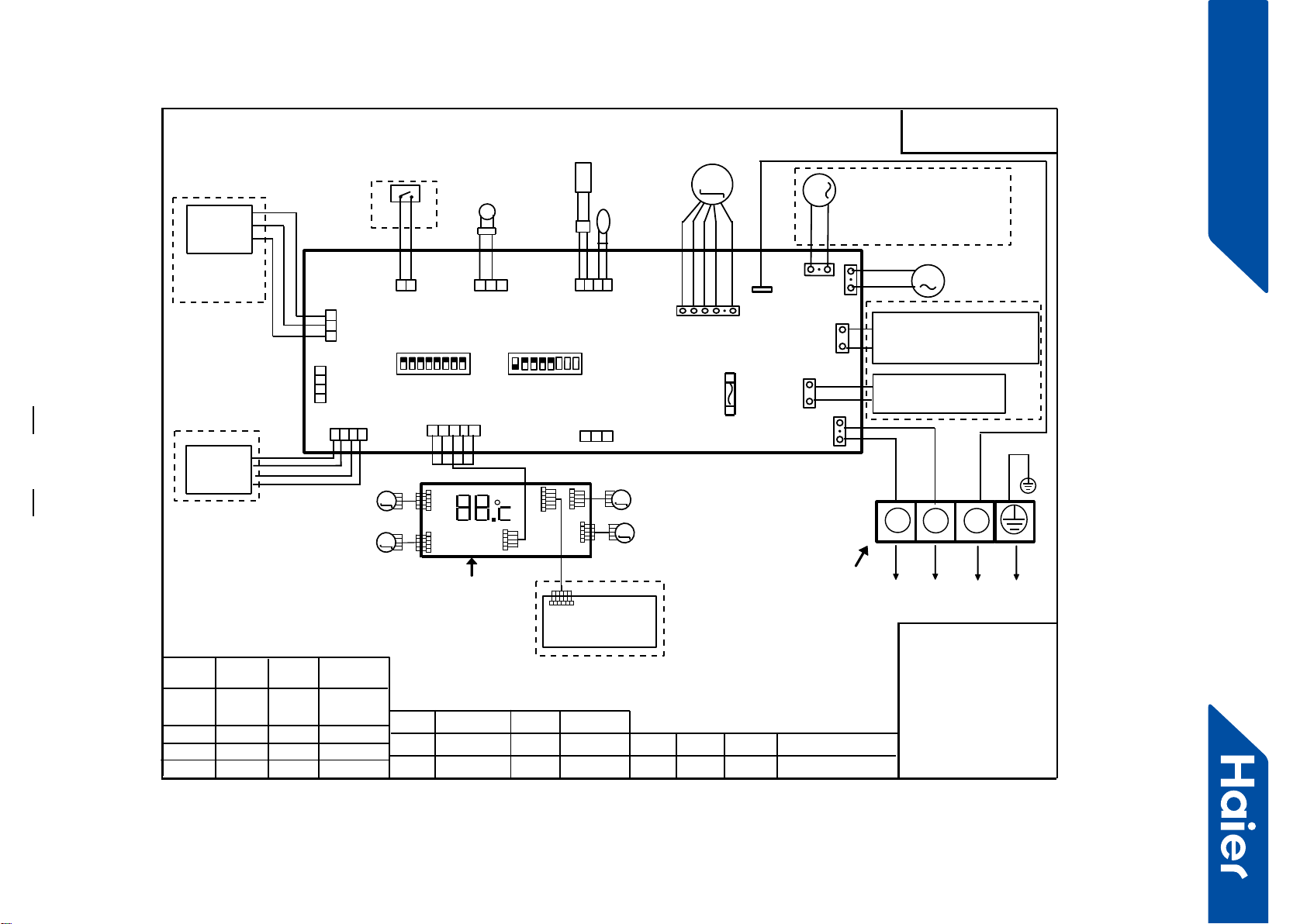
4. PCB Conguration
TO OUT DOOR UNIT
SW1-1
TYPE DEFINE
Cassette
Y/G:YELLOW/GREEN
RD:RED WHT:WHITE
BLK:BLACK
******************
.
SENSOR
CN1
CN11
CN19
SW3(BM3)
2
13
BLK
WHT
RD
NOTE:
1.DASHED PARTS ARE OPTIONAL.
2.USER SHOULD NOT CHANGE THE
DIP SWITCH SW1 SW3 WITHOUT GUIDENCE
3.SW3-5->SW3-8 ARE USED FOR WIRED CONTROLLER
ADRESS SELECT. SW3-1->SW3-4 ARE RESERVED.
CH1
OFF
OFF
TEMP
.
PIPING
DC FAN MOTOR
BA C
87654321
SW1(BM1)
87654321
N
(SLIM)
Room card
available
ON
Y/G
0150516956U
L
I.R .RECEIVER
(WITH DIGITAL
DISPLAY)
WiFi
MODULE
.
B
AC
WIRED
CONTROLLER
M
SENSOR
TEMP.
ROOM
ROOM CARD
CN3
CN6
T5A 250VAC CN16
DRAIN
PUMP
M
CN9
CN10
CN4 CN14
FUSE
FLOAT
SWITCH
CN13
CN4
CN3
CN2
CN7
CN1
CN6
INTELLIGENT
MOVE EYE DEVICE
M
M
LOUVER
STEP MOTOR4
LOUVER
STEP MOTOR3
M
M
LOUVER STEP
MOTOR2
LOUVER STEP
MOTOR1
INDOOR UNIT
MAIN CONTROL
BOARD
I.R .RECEIVER :
INFRARED REMOTE
RECEIVER .
TEMP.:TEMPERATURE
ON
OFF
ON
CN26
AB
M
FRESH AIR MOTOR /
EXTERNAL ALARM OUTPUT
(FUNCTION IN FUTURE )
( Contact rating_230VAC,3A)
CAPACITY
(BTU/H)
SW1-2 SW1-3
OFF ON
ON
ON ON
ON
SW1-4
unavailable
OFF
ON
SW1-5
COOL HEAT
COOL ONLY
HEAT PUMP
SW1-6 SW1-7 SW1-8
OFF OFF
INDOOR UNIT
TERMINAL BLOCK
CN8
24000
ON
ON OFF
ELECTRIC HEATING TERMINAL
RATING_230VAC,3A
CONNECT TO THIRD PARTY RELAY
CN15
ELECTRIC HEATING
THERMOSTAT / FUSE
OFF
36000
42000
48000
ON ON
ON

26
FlexFit Pro
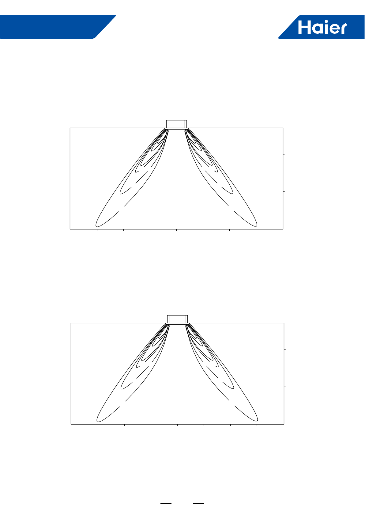
5. Air velocity and temperature distribution
AL24/36LP2VHA:
a. Cooling and air velocity
Cooling
33 degree ap angle
Air velocity distribution
b. Cooling and temperatures
Cooling
33 degree ap angle
Temperature distribution
2.5m/s 2.5m/s
1.5m/s 1.5m/s
0.5m/s
0.5m/s
13ft 13ft
9.8ft
9.8ft 6.6ft 3.3ft 0ft 3.3ft 6.6ft
0ft
3.3ft
6.6ft
8.9ft
13ft 13ft
9.8ft
9.8ft 6.6ft 3.3ft 0ft 3.3ft 6.6ft
0ft
3.3ft
6.6ft
8.9ft
62.6
O
F
68
O
F
72
O
F
62.6
O
F
68
O
F
72
O
F
27
FlexFit Pro
c. Heating and air velocity
Heating
60 degree ap angle
Air velocity distribution
d. Heating/Temperature distribution
Heating
60 degree ap angle
Temperature distribution
3.0m/s 3.0m/s
2.0m/s 2.0m/s
1.0m/s
1.0m/s
13ft 13ft
9.8ft
9.8ft 6.6ft 3.3ft 0ft 3.3ft 6.6ft
0ft
3.3ft
6.6ft
8.9ft
0ft
3.3ft
6.6ft
8.9ft
13ft 13ft
9.8ft
9.8ft 6.6ft 3.3ft 0ft 3.3ft 6.6ft
79OF
84OF
90OF90OF
84OF
79OF

28
FlexFit Pro
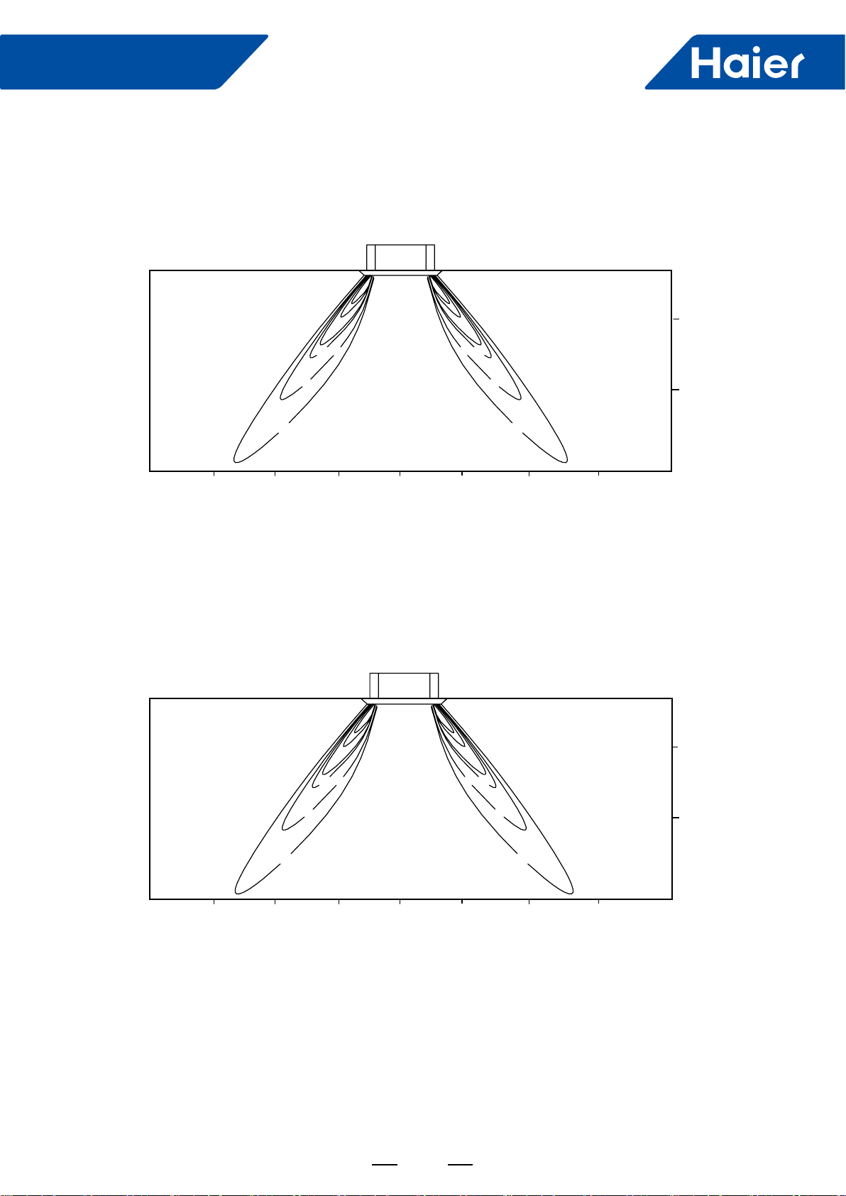
AL48LP2VHA
a. Cooling and air velocity
Cooling
33 degree ap angle
Air velocity distribution
b. Cooling and temperatures
Cooling
33 degree ap angle
Temperature distribution
2.5m/s 3.0m/s
1.5m/s 2.0m/s
0.5m/s
1.0m/s
13ft 13ft
9.8ft9.8ft 6.6ft 3.3ft 0ft 3.3ft 6.6ft
0ft
3.3ft
6.6ft
8.9ft
13ft 13ft
9.8ft9.8ft 6.6ft 3.3ft 0ft 3.3ft 6.6ft
0ft
3.3ft
6.6ft
8.9ft
64.4
O
F
70
O
F
73
O
F
64.4OF
70
O
F
73
O
F
29
FlexFit Pro
c. Heating and air velocity
Heating
60 degree ap angle
Air velocity distribution
d. Heating and temperatures
Heating
60 degree ap angle
Temperature distribution
3.5m/s 3.5m/s
2.5m/s 2.5m/s
1.5m/s
1.5m/s
13ft 13ft
9.8ft
9.8ft 6.6ft 3.3ft 0ft 3.3ft 6.6ft
0ft
3.3ft
6.6ft
8.9ft
0ft
3.3ft
6.6ft
8.9ft
13ft 13ft
9.8ft
9.8ft 6.6ft 3.3ft 0ft 3.3ft 6.6ft
91
O
F
86
O
F
81
O
F
91
O
F
86
O
F
81
O
F
30
FlexFit Pro
6. Installation
ENGLISH
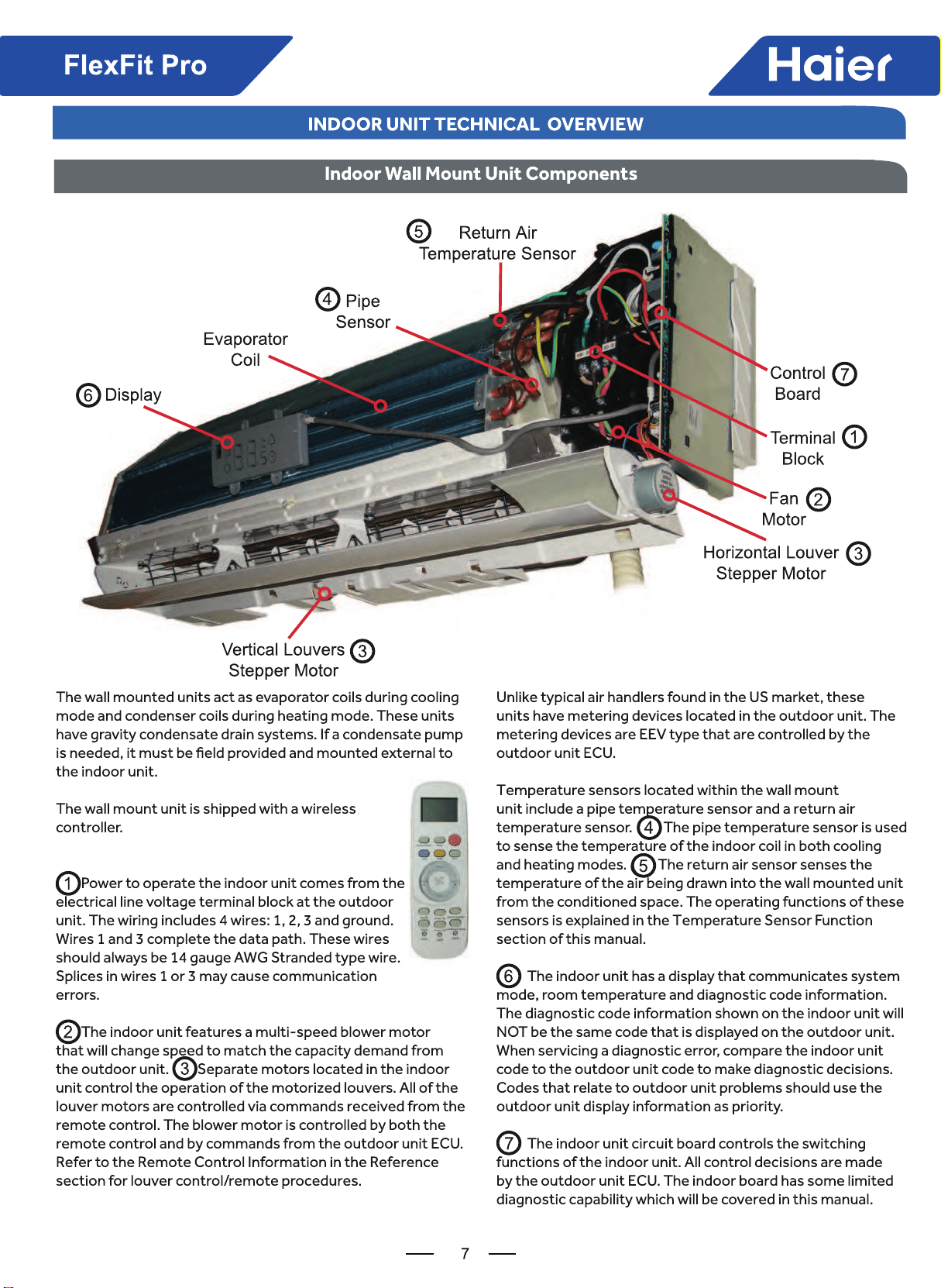
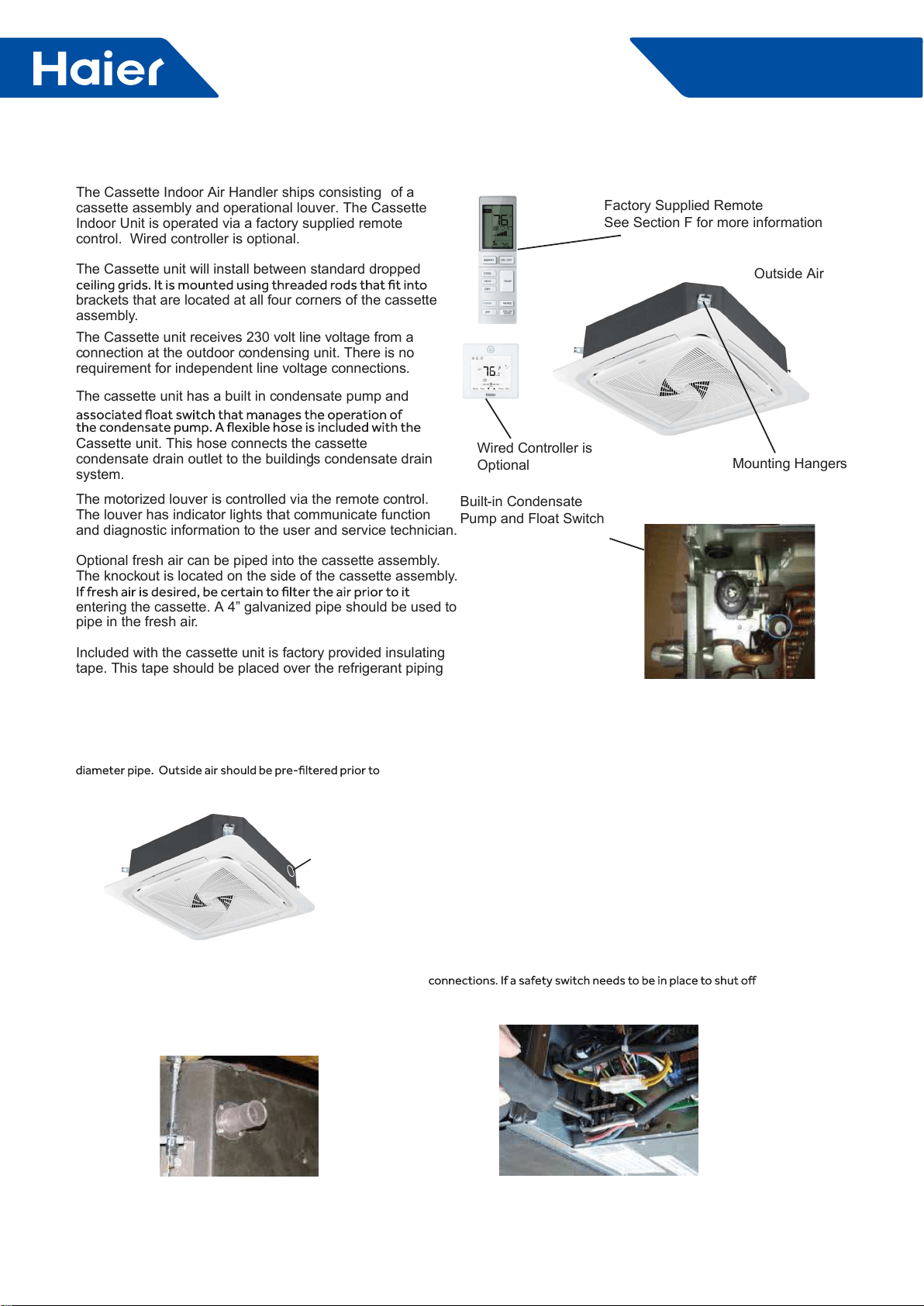
The Cassette Indoor Air Handler ships consisting of a
cassette assembly and operational louver. The Cassette
Indoor Unit is operated via a factory supplied remote
control. Wired controller is optional.
The Cassette unit will install between standard dropped
brackets that are located at all four corners of the cassette
assembly.
The Cassette unit receives 230 volt line voltage from a
connection at the outdoor condensing unit. There is no
requirement for independent line voltage connections.
The cassette unit has a built in condensate pump and
Cassette unit. This hose connects the cassette
condensate drain outlet to the building's condensate drain
system.
The motorized louver is controlled via the remote control.
The louver has indicator lights that communicate function
and diagnostic information to the user and service technician.
Optional fresh air can be piped into the cassette assembly.
The knockout is located on the side of the cassette assembly.
entering the cassette. A 4” galvanized pipe should be used to
pipe in the fresh air.
Included with the cassette unit is factory provided insulating
tape. This tape should be placed over the refrigerant piping
Built-in Condensate
Pump and Float Switch
Factory Supplied Remote
See Section F for more information
Wired Controller is
Optional
Outside Air
Mounting Hangers
Introduction - Overview
Fresh Air Intake Option
The cassette has a marked area to cut out if outside air is
desired. The piping connection should be made with a 4 inch
entry in to the cassette.
Electrical Power
Foll ow all local codes and regulations when installing electrical
wiring.
Route required electrical p ower t o area where cassette is to
be located. Maintain at least a 10 foot separation be tween TV
and Radio wiring and the power to the indoor unit.
14 /4 A WG stranded wire should be used to make the
electrical connection be tween indoor and outdoor units .
This wiring will serve t o power the indoor unit and establish a
communication link be tween indoor and outdoor units .
The wiring is connected at the indoor unit electrical terminal
blocks screws 1, 2, 3 and ground. There should be no
splices in the wires connected to terminals 1 or 3 as these
serve as communication signal wires and electrical p ower
power to the indoor unit, break wire 2 onl y.
Condensate Handling
The Cassette unit has a built in c ondensate pump and water
level safety switch. There is no option for gravity drain. The
condensate pump is r ated to lift water up to 24” from the
point of discharge on the casse tte assembly.
Intr oduction - Overview
Fresh air
knock out
31
FlexFit Pro
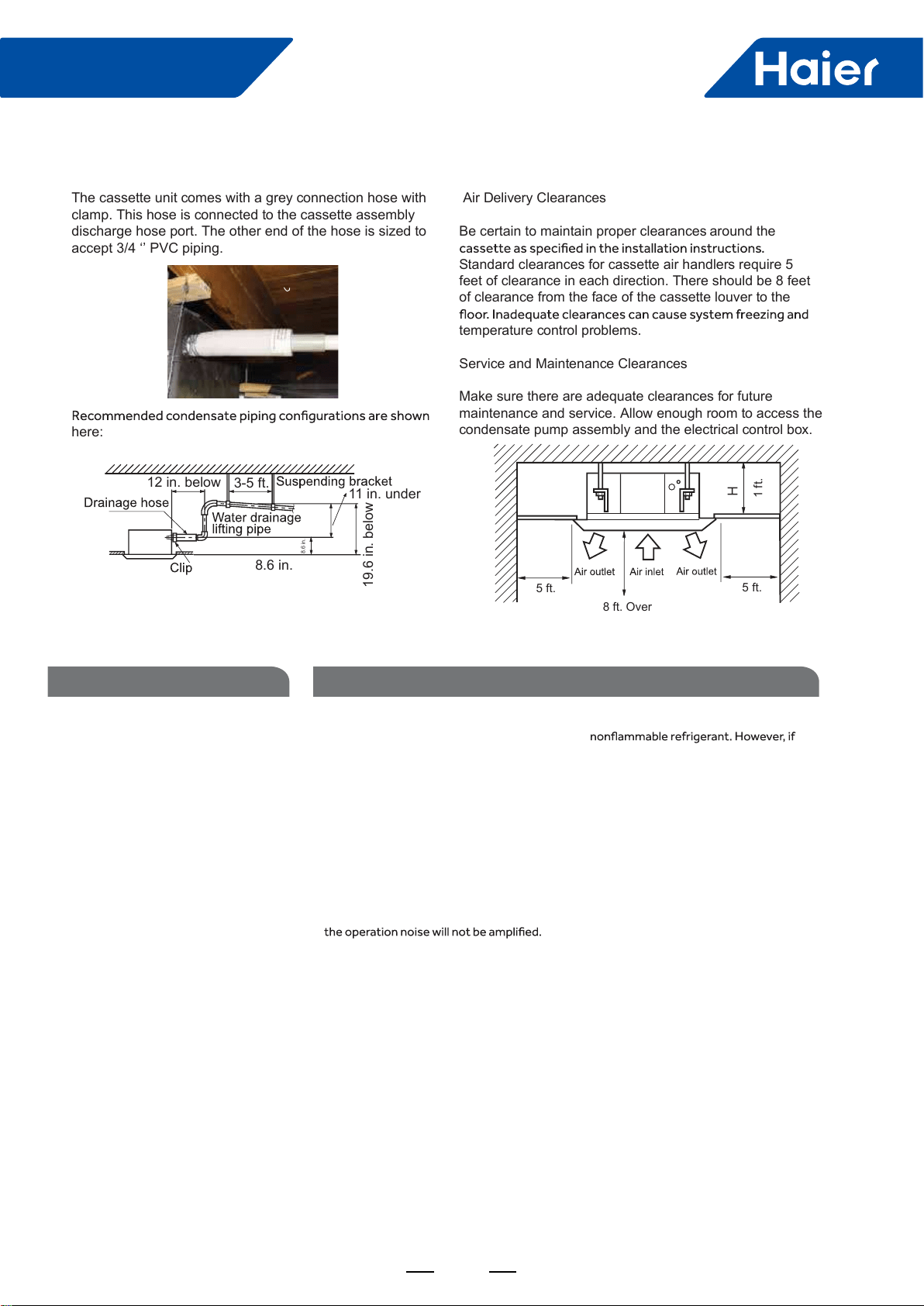
Air Delivery Clearances
Be certain to maintain proper clearances around the
Standard clearances for cassette air handlers require 5
feet of clearance in each direction. There should be 8 feet
of clearance from the face of the cassette louver to the
temperature control problems.
Service and Maintenance Clearances
Make sure there are adequate clearances for future
maintenance and service. Allow enough room to access the
condensate pump assembly and the electrical control box.
The cassette unit comes with a grey connection hose with
clamp. This hose is connected to the cassette assembly
discharge hose port. The other end of the hose is sized to
accept 3/4 ‘’ PVC piping.
here:
5 ft. 5 ft.
1 ft.
8 ft. Over
12 in. below 3-5 ft. 11 in. under
8.6 in.
8.6 in.
19.6 in. below
Step 1 - Preparation
Procedure for Selecting the LocationRequired Tools for Installation
• Drill
• Wire Snipper
• Hole Saw 2 3/4”
• Vacuum pump
• Soap-and-water solution or gas leakage
detector
• Torque wrench
• 17mm, 22mm, 26mm
• Tubing cutter
• Flaring tool
• Razor knife
• Measuring tape
• Level
• Micron gauge
• Nitrogen
• Mini-Split AD-87 Adapter (1/4” to 5/16”)
• A - Non-adhesive Tape
• B - Adhesive Tape
• C - Saddle (L.S.) with screws
• D - Electrical wiring
• E - Drain hose (Included)
• F - Insulation
• G - Piping hole cover (Included)
Note:
1) R-410A refrigerant is a safe, nontoxic and
there is a concern about a dangerous level
of refrigerant concentration in the case of
refrigerant leakage, add extra ventilation.
• Place above the ceiling where you have
enough space to position the unit.
• Place where the drainage pipe can be
properly positioned.
• Place where the inlet and outlet air of the
indoor unit will not be blocked.
• Do not install the unit in a place with
heavy oil or moisture (e.g. - kitchens and
workshops)
• Do not install in a location with destructive
gas (such as sulfuric acid gas) or pungent
gas (thinner and gasoline) are used or
stored.
• Choose a place solid enough to bear the
weight and vibration of the unit and where
• Install where there are no expensive items
like a television or piano below the indoor
unit.
• Leave enough space for maintenance.
• Install at least 3 ft. away from televisions
and radios to avoid interference.
32
FlexFit Pro
ENGLISH
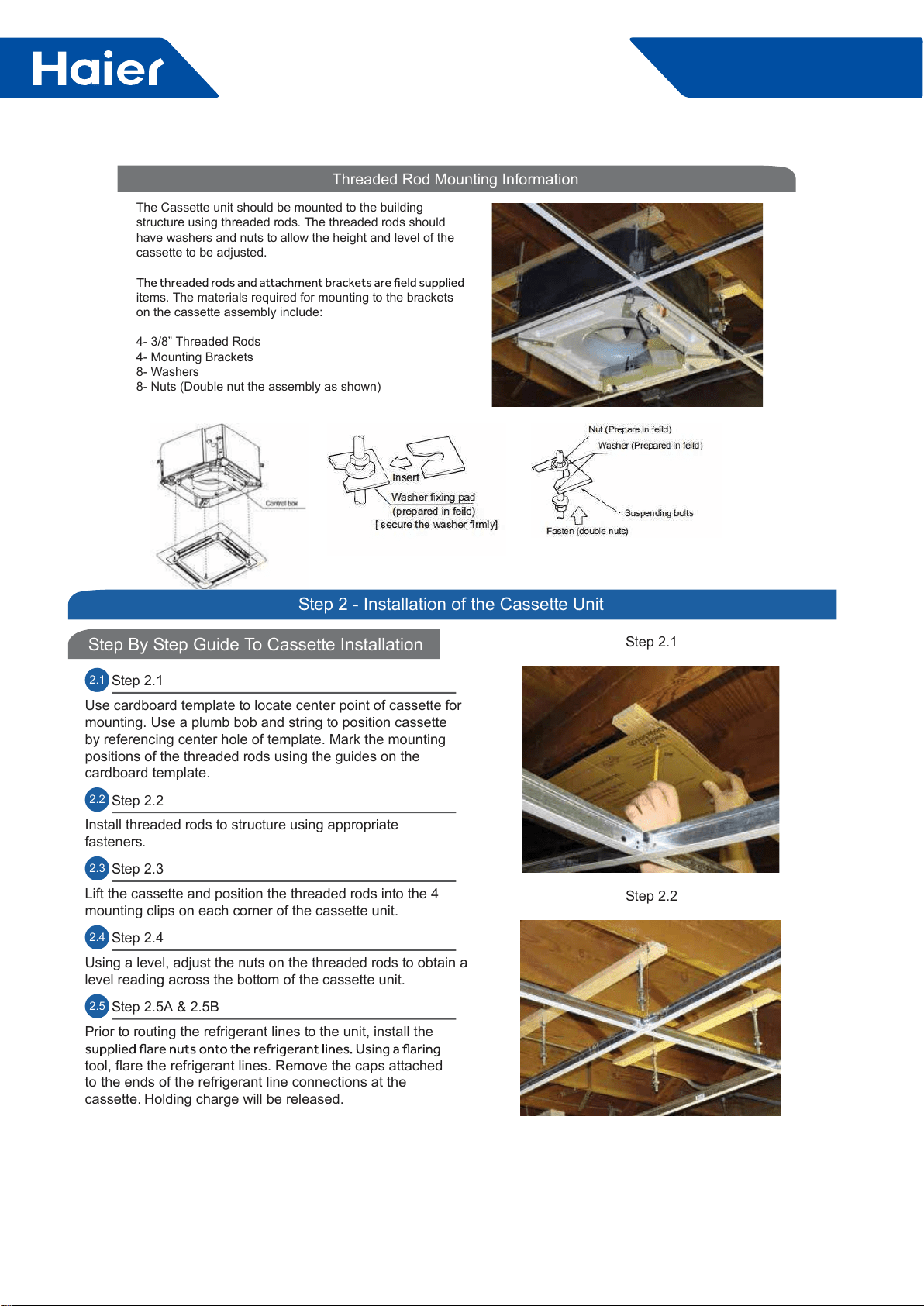
Threaded Rod Mounting Information
The Cassette unit should be mounted to the building
structure using threaded rods. The threaded rods should
have washers and nuts to allow the height and level of the
cassette to be adjusted.
items. The materials required for mounting to the brackets
on the cassette assembly include:
4- 3/8” Threaded Rods
4- Mounting Brackets
8- Washers
8- Nuts (Double nut the assembly as shown)
SECTION C
Step By Step Guide To Cassette Installation
Step 2 - Installation of the Cassette Unit
2.1 Step 2.1
Use cardboard template to locate center point of cassette for
mounting. Use a plumb bob and string to position cassette
by referencing center hole of template. Mark the mounting
positions of the threaded rods using the guides on the
cardboard template.
2.2 Step 2.2
Install threaded rods to structure using appropriate
fasteners.
2.3 Step 2.3
Lift the cassette and position the threaded rods into the 4
mounting clips on each corner of the cassette unit.
2.4 Step 2.4
Using a level, adjust the nuts on the threaded rods to obtain a
level reading across the bottom of the cassette unit.
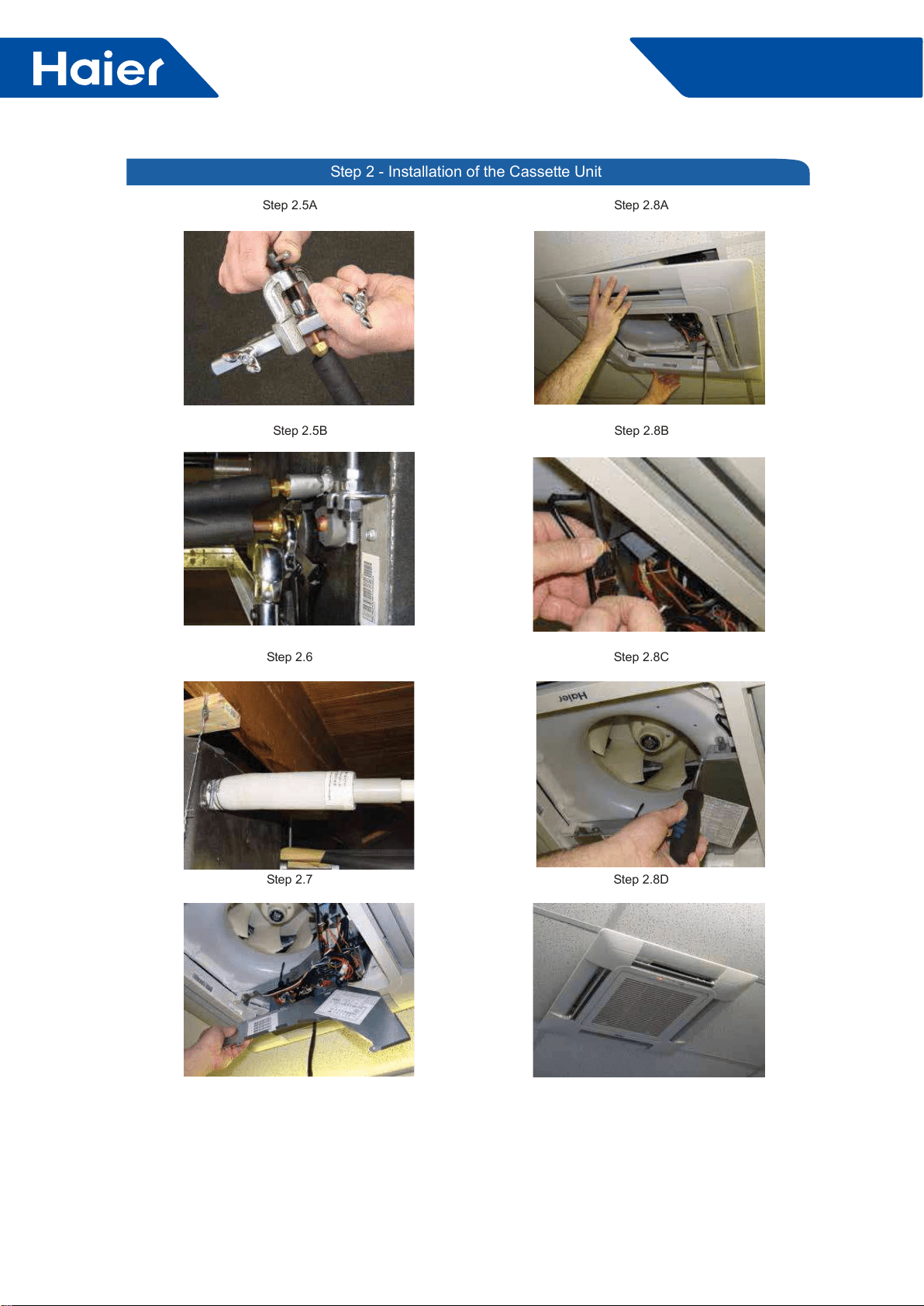
2.5 Step 2.5A & 2.5B
Prior to routing the refrigerant lines to the unit, install the
tool, flare the refrigerant lines. Remove the caps attached
to the ends of the refrigerant line connections at the
cassette. Holding charge will be released.
Step 2.1
Step 2.2
33
FlexFit Pro
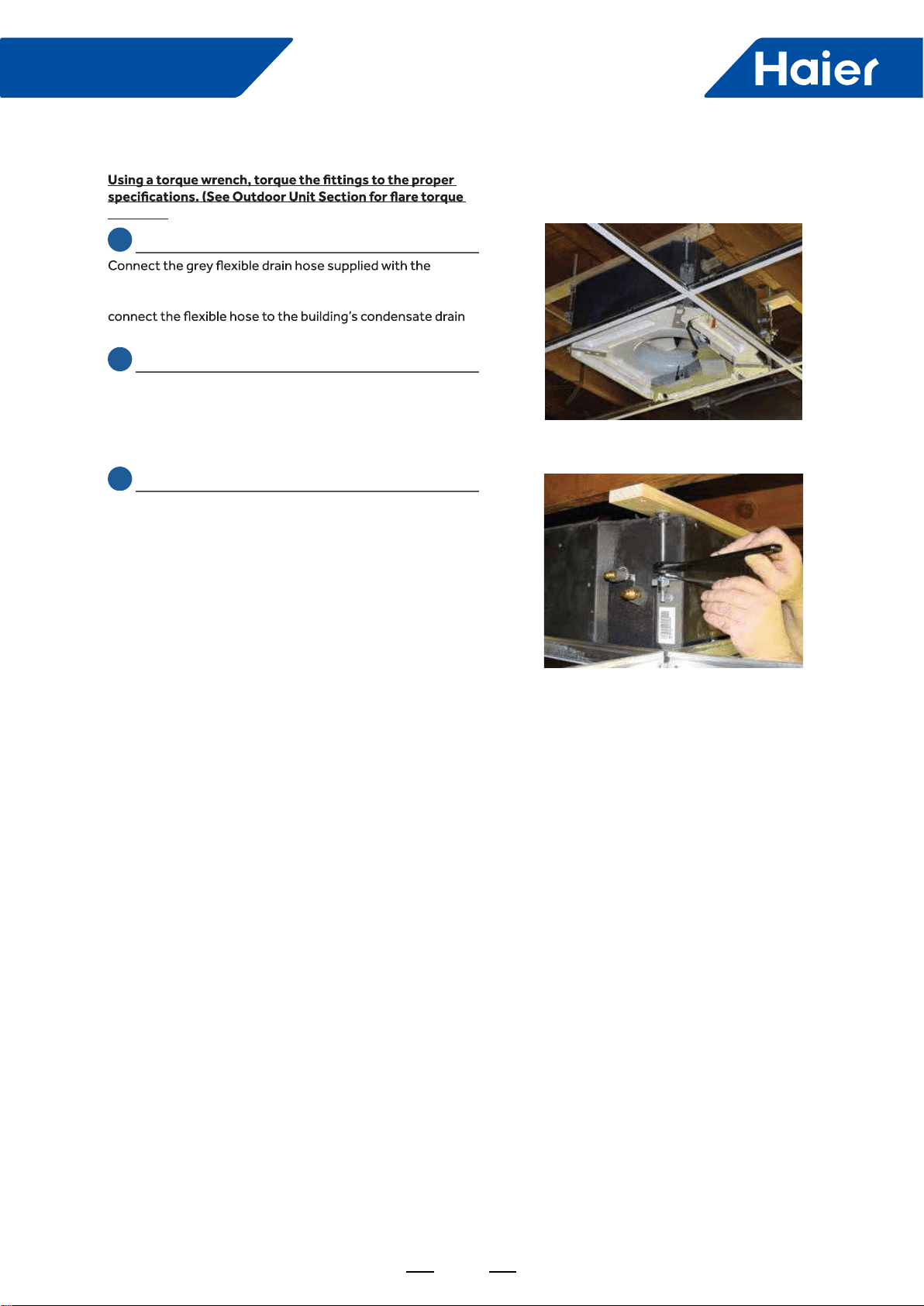
SECTION C
settings.)
2.6 Step 2.6
cassette unit to the condensate pump discharge pipe of
the cassette. Tighten the clamp securely. Using 3/4 “ PVC,
system.
2.7 Step 2.7
Remove the electrical box cover. Remove the rubber
grommet and insert a 1/2 inch electrical connector and
reducing washer. Route electrical wiring into cassette unit.
Connect to wire terminas as indicated in schematic drawing.
(USE 14 AWG Stranded wire only.)
2.8 Step 2.8A & 2.8B ,C, D
Connect Louver assembly to cassette assembly. Connect
wires from louver to the harness on the cassette assembly.
There are two wire connections. (See photo for connections.)
Secure louver with four screws.
Reinstall electrical box cover.
Install return air grille into louver assembly.
Installation is now complete.
Step 2.3
Step 2.4
34
FlexFit Pro
ENGLISH
Step 2 - Installation of the Cassette Unit
Step 2.5B
Step 2.7
Step 2.8B
Step 2.5A
Step 2.6
Step 2.8A
Step 2.8D
Step 2.8C
35
FlexFit Pro

36
FlexFit Pro
Part 4 Indoor Units-High Static Duct Type
1. Features ............................................................................................................................................................37
....................................................................................................................................................38
3. Dimensions ........................................................................................................................................................41
4. Wiring diagrams ................................................................................................................................................43
5. Instalaltion .........................................................................................................................................................45
37
FlexFit Pro
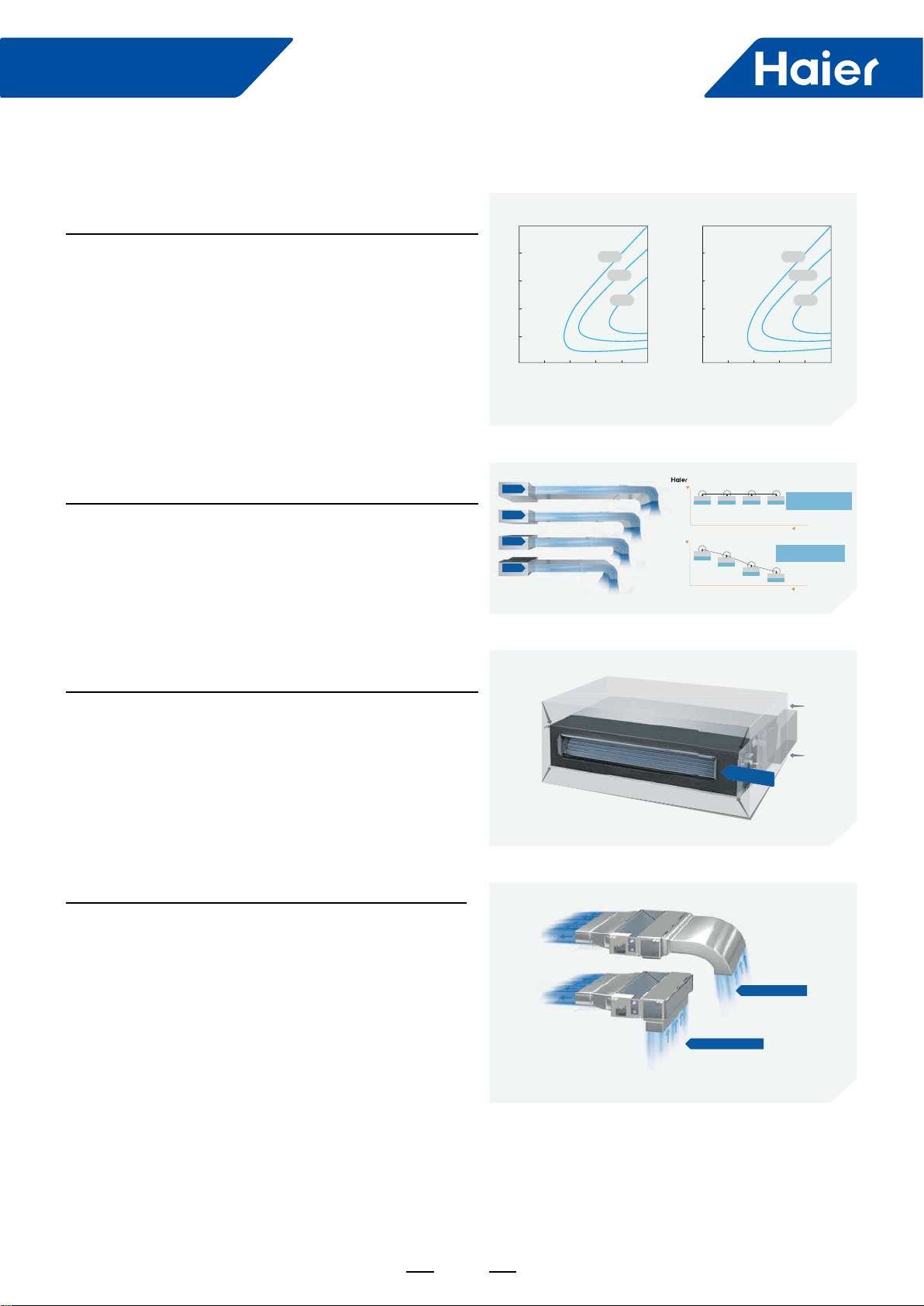
High Effciency
DC Fan Motor
Achieves higher efciency as compared to a conventional
AC motor. See chart.
Comfortable
Consistent Air Flow
Up to 3 fans maintain desired air volume as static pressure
changes.
Slim Design
10" cabinet height means easier installation in a wide variety
Return Air Options
Installer-friendly design; choose rear or bottom return
conguration.
1. Features
20
02004006008001000
40
60
80
100
40%
35%
25%
20
0200400 600 800 1000
40
60
80
100
90%
87.5%
85%
Torque(kgfcm)
Rev(r/min)
AC motor efficiency DC motor efficiency
Rev(r/min)
Torque(kgfcm)
120Pa
100Pa
70Pa
50Pa
Air Flow
2500
2000
50po 70po 100po 120po ESP
1500
2500
100%
m/h³ 2500
100%
m/h³ 2500
100%
m/h³
2500
100%
m/h³ 100% airflow when the ESP
reach 120pa for Haier duct
Air Flow
2500
2000
50po 70po 100po 120po ESP
1500
100%
2500m/h³
90%
2250m/h³
76%
1900m/h³
68%
1700m/h³
Oniy 68% airflow when the ESP
reach 120pa for traditional duct
Common
250
250
mm
250
mm
Rear air return
Bottom air return

38
FlexFit Pro
2. Specications
Model Name
System AM24LP
Outdoor 1U24LP2VHA
Indoor AM24LP2VH*
Cooling
Rated Capacity Btu/hr 24000
Capacity Range Btu/hr 6800-30700
Rated Power Input W2,182
SEER 17
EER 11
Moisture Removal Pt./h 5.1
Heating
Rate Heating Capacity 47°F Btu/hr 26500
Heating Capacity Range Btu/hr 6800-34100
Rated Power Input W2,089
HSPF 11
Operating Range Cooling °F(°C) 0~115F(-18-46C)*
Heating °F(°C) -4°F~75°F (-20-24℃)
Power Supply Voltage, Cycle, Phase V/Hz/- 208-230/60/1
Outdoor Unit
Compressor Type DC Inverter Driven Rotary
Maximum Fuse Size A 25.0
Minimum Circuit Amp A 21.0
Outdoor Fan Speed RPM 750/700/650/600/500/400/300
Outdoor Noise Level dB 47
Dimension: Height in (mm) 38 (965)
Dimension: Width in (mm) 37 3/8(950)
Dimension: Depth in (mm) 14 5/8(370)
Weight (Ship/Net)- lbs (kg) 202.8/ 176.4 (92/80)
Indoor Unit
Fan Speed Stages 4 + Auto
Airow (Turbo/High/Med/Low/Quiet) CFM 845/670/530/470
Motor Speed (Turbo/High/Med/Low/Quiet) RPM 950/860/760/700
Indoor Sound Level dB (Turbo/High/Med/Low/Quiet) 38/35/32/29
Dimension: Height in (mm) 9 7/8 (250)
Dimension: Width in (mm) 37 5/8 (957)
Dimension: Depth in (mm) 25 3/4 (655)
Max. External Static Pressure in.W.G(Pa) 0.6(150)
Drainpipe Size O.D. in 1 1/4
Internal Condensate Pump Standard
Max. Drain-Lift height in(mm) 27 9/16(700)
Grill Model NA
Grill Dimension: Height in (mm) NA
Grill Dimension: Width in (mm) NA
Grill Dimension: Depth in (mm) NA
Weight (Ship/Net)- lbs (kg) "81.1/68.8
(36.8/31.2)"
Refrigerant Lines
Connections Flare
Liquid O.D. in 3/8
Suction O.D. in 5/8
Factory Charge Oz 88.2
Maximum Line Length Ft / m 165/50
Maximum Height Ft / m 100/30

39
FlexFit Pro
Model Name
System AM36LP
Outdoor 1U36LP2VHA
Indoor AM36LP2VH*
Cooling
Rated Capacity Btu/hr 35000
Capacity Range Btu/hr 8500-37500
Rated Power Input W3,500
SEER 17
EER 10
Moisture Removal Pt./h 6.8
Heating
Rate Heating Capacity 47°F Btu/hr 37500
Heating Capacity Range Btu/hr 8500-41000
Rated Power Input W3,283
HSPF 10.5
Operating Range Cooling °F(°C) 0~115F(-18-46C)*
Heating °F(°C) -4°F~75°F (-20-24℃)
Power Supply Voltage, Cycle, Phase V/Hz/- 208-230/60/1
Outdoor Unit
Compressor Type DC Inverter Driven Rotary
Maximum Fuse Size A 30
Minimum Circuit Amp A 26.0
Outdoor Fan Speed RPM 750/700/650/600/500/400/300
Outdoor Noise Level dB 52
Dimension: Height in (mm) 38 (965)
Dimension: Width in (mm) 37 3/8(950)
Dimension: Depth in (mm) 14 5/8(370)
Weight (Ship/Net)- lbs (kg) 207.2/180.7 (94/82)
Indoor Unit
Fan Speed Stages 4 + Auto
Airow (Turbo/High/Med/Low/Quiet) CFM 1100/950/735/675
Motor Speed (Turbo/High/Med/Low/Quiet) RPM 1000/920/860/810
Indoor Sound Level dB (Turbo/High/Med/Low/Quiet) 32/28/25/23
Dimension: Height in (mm) 9 7/8 (250)
Dimension: Width in (mm) 59 (1500)
Dimension: Depth in (mm) 28 3/8 (720)
Max. External Static Pressure in.W.G(Pa) 0.6(150)
Drainpipe Size O.D. in 1 1/4
Internal Condensate Pump Standard
Max. Drain-Lift height in(mm) 27 9/16(700)
Grill Model NA
Grill Dimension: Height in (mm) NA
Grill Dimension: Width in (mm) NA
Grill Dimension: Depth in (mm) NA
Weight (Ship/Net)- lbs (kg) 130.1/121.3 (59/55)
Refrigerant Lines
Connections Flare
Liquid O.D. in 3/8
Suction O.D. in 5/8
Factory Charge Oz 88.2
Maximum Line Length Ft / m 165/50
Maximum Height Ft / m 100/30
40
FlexFit Pro
Model Name
System AM48LP
Outdoor 1U48LP2VHA
Indoor AM48LP2VH*
Cooling
Rated Capacity Btu/hr 47000
Capacity Range Btu/hr 11900-54500
Rated Power Input W4,476
SEER 17
EER 10.5
Moisture Removal Pt./h 11.0
Heating
Rate Heating Capacity 47°F Btu/hr 52000
Heating Capacity Range Btu/hr 13600-64800
Rated Power Input W4,407
HSPF 10
Operating Range Cooling °F(°C) 0~115F(-18-46C)*
Heating °F(°C) -4°F~75°F (-20-24℃)
Power Supply Voltage, Cycle, Phase V/Hz/- 208-230/60/1
Outdoor Unit
Compressor Type DC Inverter Driven Rotary
Maximum Fuse Size A 40
Minimum Circuit Amp A 35.0
Outdoor Fan Speed RPM 750/700/650/600/500/400/300
Outdoor Noise Level dB 53
Dimension: Height in (mm) 53 1/8 (1350)
Dimension: Width in (mm) 37 3/8(950)
Dimension: Depth in (mm) 14 5/8(370)
Weight (Ship/Net)- lbs (kg) 260.1/231.5 (118/105)
Indoor Unit
Fan Speed Stages 4 + Auto
Airow (Turbo/High/Med/Low/Quiet) CFM 1350/1150/930/765
Motor Speed (Turbo/High/Med/Low/Quiet) RPM 1180/1080/1010/960
Indoor Sound Level dB (Turbo/High/Med/Low/Quiet) 41/36/33/31
Dimension: Height in (mm) 9 7/8 (250)
Dimension: Width in (mm) 59 (1500)
Dimension: Depth in (mm) 28 3/8 (720)
Max. External Static Pressure in.W.G(Pa) 0.6(150)
Drainpipe Size O.D. in 1 1/4
Internal Condensate Pump Standard
Max. Drain-Lift height in(mm) 27 9/16(700)
Grill Model NA
Grill Dimension: Height in (mm) NA
Grill Dimension: Width in (mm) NA
Grill Dimension: Depth in (mm) NA
Weight (Ship/Net)- lbs (kg) 132.3/114.6 (60/52)
Refrigerant Lines
Connections Flare
Liquid O.D. in 3/8
Suction O.D. in 5/8
Factory Charge Oz 131
Maximum Line Length Ft / m 230/75
Maximum Height Ft / m 100/30
41
FlexFit Pro
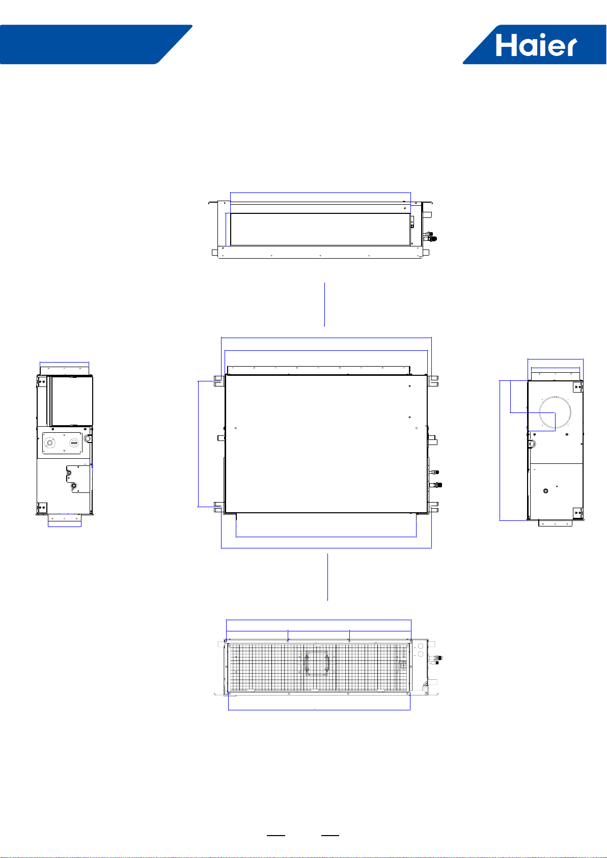
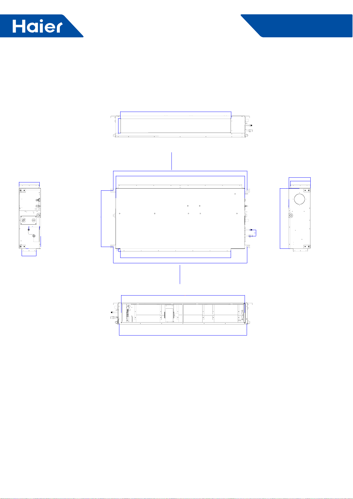
3. Dimensions
3.1 AM24LP2VHA
air inlet
air outlet
31 1/2 (800)
5 11/16(145)
38 11/16(983)
37 5/16(947)
23 3/16(589)
31 1/2(800)
38 11/16(983)
2 3/8(60)
25 13/16(655)
5 7/8(150)
9 13/16(250)
9 (230)
5 3/16(131)
34(863)
11 5/16(288) 11 5/16(288) 11 5/16(288)
33 1/2(850)
9 5/16(235)
5 11/16(145)
42
FlexFit Pro
3.2 AM36LP2VHA AM48LP2VHA
return air
supply air
50 5/8(1286)
6 5/8(168)
61 1/4(1556)
59(1500)
25 11/16(653)
50 5/8(1286)
61 5/16(1556)
6 5/8(168)
9 1/4(235) 9 1/4(235)
9 7/8(251)
27 5/8(701)
58 1/2(1486)
56 1/2(1435)
43
FlexFit Pro
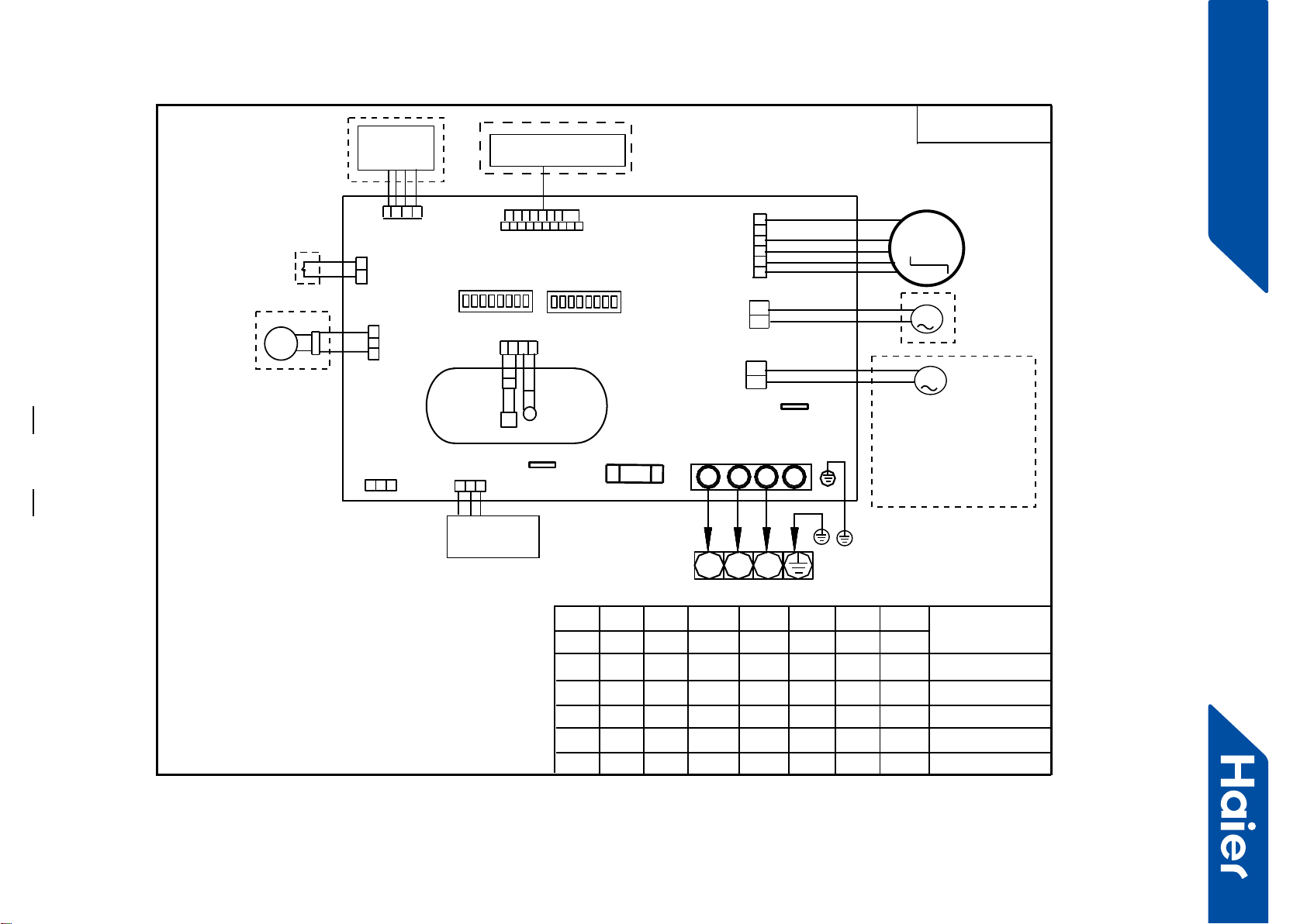
4. Wiring diagrams
AM24LP2VHA
Y/G:YELLOW/GREEN
NOTE:
1.DASHED PARTS ARE OPTIONAL.
2.SW03-4 IS AT ON POSITION,DO NOT CHANGE
THE SETTINGS OF SWITCHS WITHOUT GUIDANCE.
3.WHEN ONE WIRED CONTROLLER CONTROL MULTIPLE INDOOR UNIT,
IT CAN CONNECT ANOTHER INDOOR UNIT BY CN22 OR CN22-1.
WHEN TWO WIRD CONTROLLERS CONTROL ONE INDOOR UNIT,
THE WIRED CONTROLLER NEED CONNECT WITH CN22 AND CN22-1.
TEMP.
SENSOR
ROOM
SENSOR
PIPING
TEMP.
ROOMCARD
ROTOM NAF CD
SW03
FUSE
WIRED
CONTROLLER
FLOAT
SWITCH
WIFI
MODULE
PUMP
TO OUT DOOR
2
13
Y/G
M
12345678
ON
REMOTE RECEIVER
M
B A
C
BA
C
OFF
0150523302
2
13
N L S
B A
C
SW01
12345678
ON
OFF
FRESH AIR MOTOR
(SW01-6 select OFF) /
EXTERNAL ALARM OUTPUT
(SW01-6 select ON)
( Contact rating_230VAC,3A)
M
CN21
Heater_L
CH4
Heater_N
CH2
CN5
CN4
CN34
CN16
CH1
SW01-1
SW01-2
SW01-3
ON
SW01-4
SW01-5
SW01-6
SW01-7
SW01-8
MODEL
OFF AM24LP2VHA
OFF OFF OFF OFF
OFF OFF OFF
ON
OFF
ON
ON ADH071M3ERG
OFF
OFF ON
CN13
CN6
CN41
CN22
CN22-1
4.SW03-5
->SW03-08 IS USED FOR
ADDRESS SETTING ON THE
SITUATION OF ONE WIRED CONTROLLER CONTROL MORE THAN
ONE INDOOR UNIT.
5.REFER TO SERVICE MANUL TO GET MUCH MORE DETAILS
ABOUT THE STATIC PRESSURE LEVEL SELECTION.
CN1
AD71S2SM1FA
OFF
OFF
OFF
OFF
OFF
OFF
ON
ON
ON
OFF OFF OFF OFF OFF OFF ON AD50S2SM1FA
SW03-1
SW03-2 SW03-3
FOR ALL DUCTED
MODEL
SW03-4 SW03-5 SW03-6 SW03-7 SW03-8
OFF OFF OFF OFF OFF OFF OFFON
FlexFit Pro
44
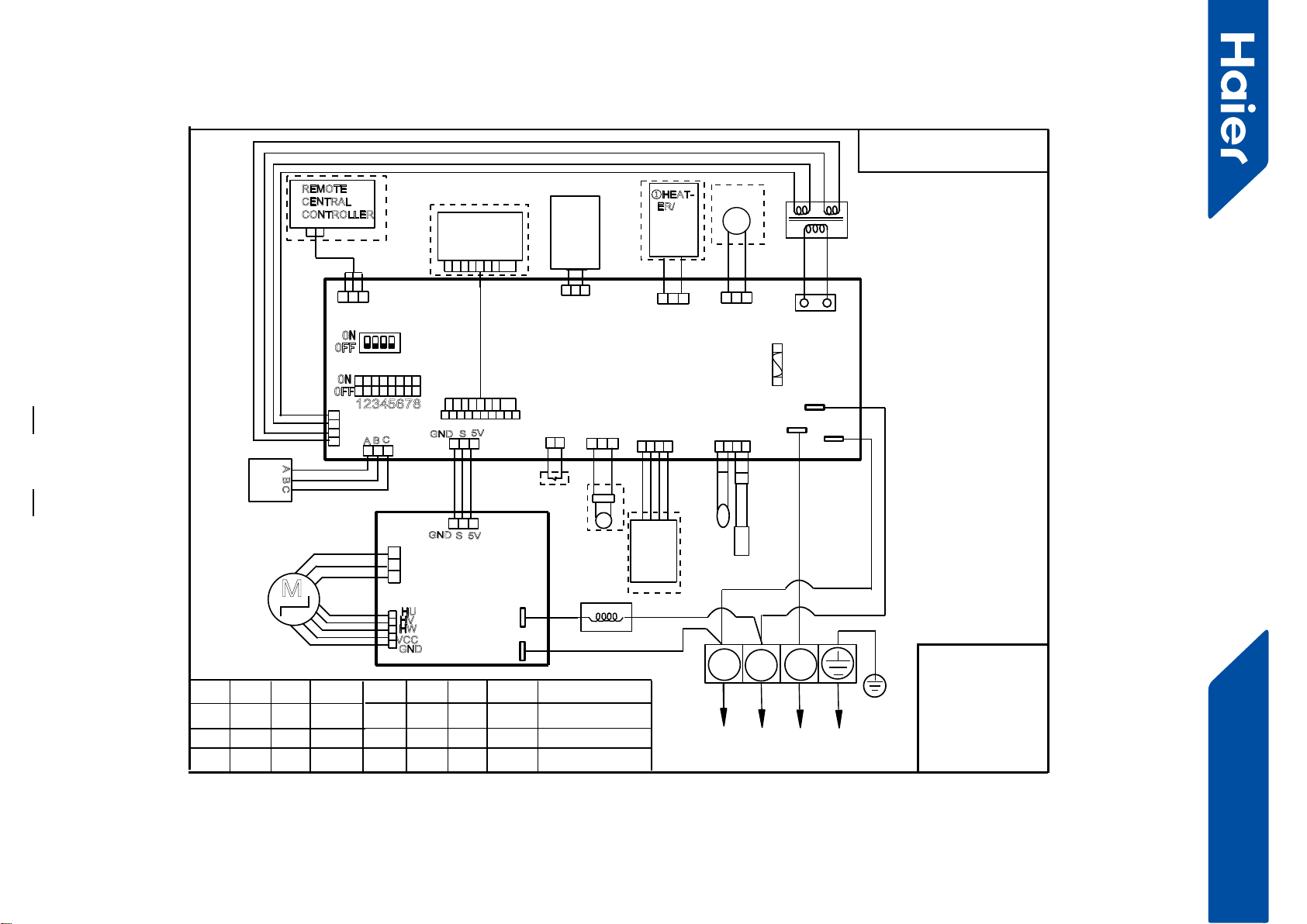
Super Match Smatr Power
AM36LP2VHA AM48LP2VHA
BLK:black BLU:blue
GR:grey
ORG:orange
PNK:pink RD:red
WHT:white YL:yellow
Y/G:
yellow/green
FLOAT
SWITCH
CN5
TRANSFORMER
PUMP
CN9
CN8
REMOTE
CENTRAL
CONTROLLER
TEMP.
SENSOR
ROOM
SENSOR
PIPING
TEMP.
CN3
CN29 CN18 CN13
CN19
T3.15A/250VAC
FUSE
WIRED
CONTROLLER
ROOM CARD
CH3(L)
CH4(N)
CH5
12345678
ON
OFF
SW1
ON
OFF
1234
SW2
~
2
13
WHT
Y/G
CN1
ABC
A B C
REMOTE
RECEIVER
INFRARED
CN4
WiFi
MODULE
GND S5V
CN6
CN7
②NEG
ATIVE
ION
GND S5V
M
FAN MOTOR
DRIVER
MODULE
MAIN CONTROL
BOARD
DC FAN
MOTOR
U
V
W
RD
WHT
BLK
CN609
CN604
P601
(ACL)
P602(ACN)
Reactor
CN603
HU
HV
HW
VCC
GND
YL
BLU
ORG
PNK
GR
WHT
RD
BLK
①HEAT-
ER/
To outdoor unit
Note:
1.Dashed parts are op-
tional.
2.marks ①②are
function in future.
3.Once out of factorty
do not change the DIP
switches without
technical guidence
4.SW2 is used for
address setting on the
situation of one wired
controller control more
than one indoor unit.
5.Use wired controller to
select appropriate exter-
nal static pressure level.
6.Refer to service
manual to get more
information about the
static pressure level
select or DIP switch
SW1,SW2 function
definations
SW1-1 SW1-2 SW1-3
ON
SW1-4 SW1-5 SW1-6 SW1-7 SW1-8 MODEL
OFF OFF OFF
CN20
OFF ON OFF
AM42LP2VHA
OFF OFF OFF ON OFF
OFF OFF OFF ON OFF
ON
ON
ON
OFF
ON
ON
ON AM48LP2VHA
AM36LP2VHA
0150517885U
M
FRESH
AIR
LINK
45
FlexFit Pro
5. Installation
ENGLISH SECTION D
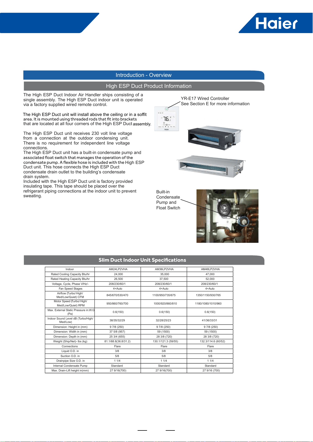
High ESP Duct Product Information
The High ESP Duct Indoor Air Handler ships consisting of a
single assembly. The High ESP Duct indoor unit is operated
via a factory supplied wired remote control.
that are located at all four corners of the High ESP Duct
The High ESP Duct unit receives 230 volt line voltage
from a connection at the outdoor condensing unit.
There is no requirement for independent line voltage
connections.
The High ESP Duct unit has a built-in condensate pump and
Duct unit. This hose connects the High ESP Duct
condensate drain outlet to the building’s condensate
drain system.
Included with the High ESP Duct unit is factory provided
insulating tape. This tape should be placed over the
refrigerant piping connections at the indoor unit to prevent
sweating. Built-in
Condensate
Pump and
Float Switch
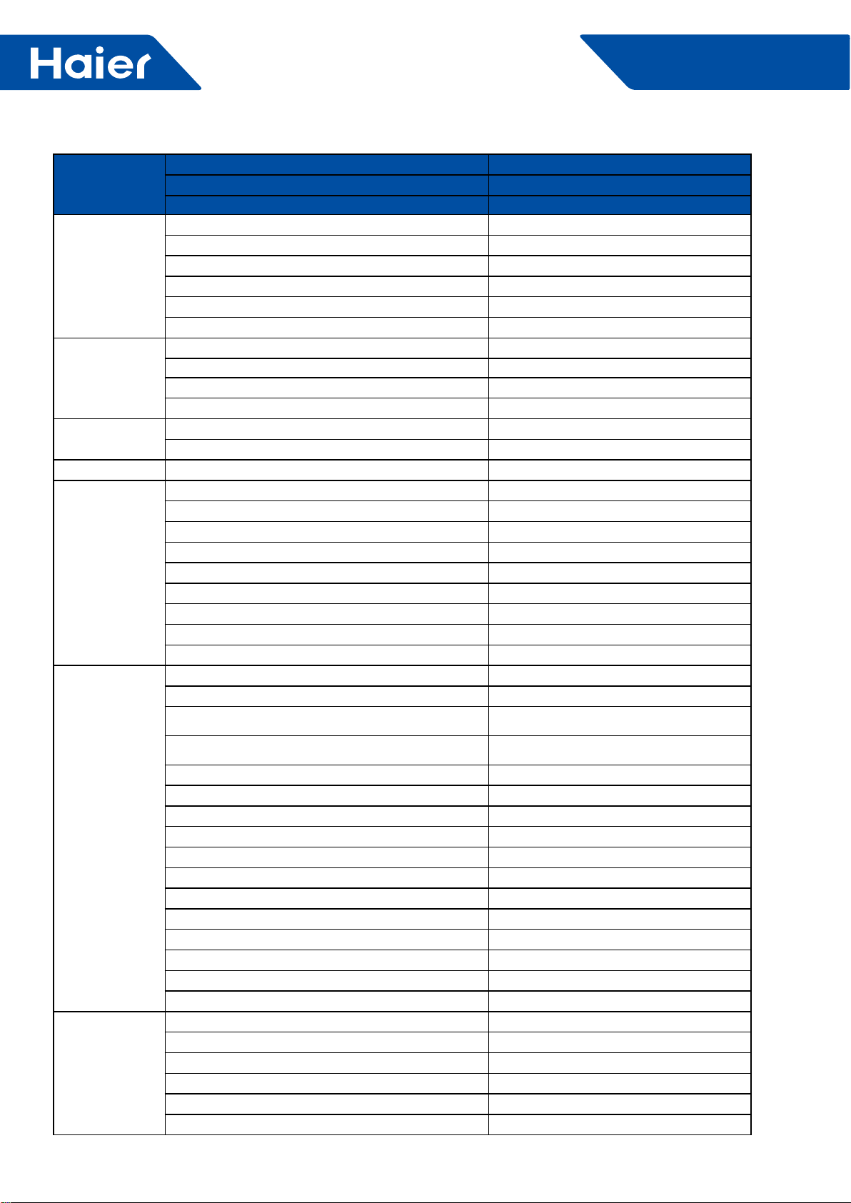
Indoor AM24LP2VHA AM36LP2VHA AM48LP2VHA
Rated Cooling Capacity Btu/hr 24,000 35,000 47,000
Rated Heating Capacity Btu/hr 26,500 37,500 52,000
Voltage, Cycle, Phase V/Hz/-
208/230/60/1 208/230/60/1 208/230/60/1
Fan Speed Stages 4+Auto 4+Auto 4+Auto
Airow (Turbo/ High/
Med/Low/Quiet) CFM 845/670/530/470 1100/950/735/675
1350/1150/930/765
Motor Speed (Turbo/ High/
Med/Low/Quiet) RPM
950/860/760/700
1000/920/860/810 1180/1080/1010/960
Max. External Static Pressure in.W.G
(Pa)
0.6(150) 0.6(150) 0.6(150)
Indoor Sound Level dB (Turbo/High/
Med/Low) 38/35/32/29 32/28/25/23
41/36/33/31
Dimension: Height in (mm)
9 7/8 (250) 9 7/8 (250) 9 7/8 (250)
Dimension: Width in (mm)
37 5/8 (957) 59 (1500) 59 (1500)
Dimension: Depth in (mm)
25 3/4 (655) 28 3/8 (720) 28 3/8 (720)
Weight (Ship/Net)- lbs (kg)
81.1/68.8(36.8/31.2) 130.1/121.3 (59/55) 132.3/114.6 (60/52)
Connections Flare Flare Flare
Liquid O.D. in 3/8 3/8 3/8
Suction O.D. in 5/8 5/8 5/8
Drainpipe Size O.D. in 1 1/4 1 1/4 1 1/4
Internal Condensate Pump
Standard
Standard Standard
Max. Drain-Lift height in(mm)
27 9/16(700) 27 9/16(700)
27 9/16 (700)
Introduction - Overview
YR-E17 Wired Controller
See Section E for more information
assembly.
High ESP
The High ESP Duct unit will install above the ceiling or in a soffit
46
FlexFit Pro
SECTION D
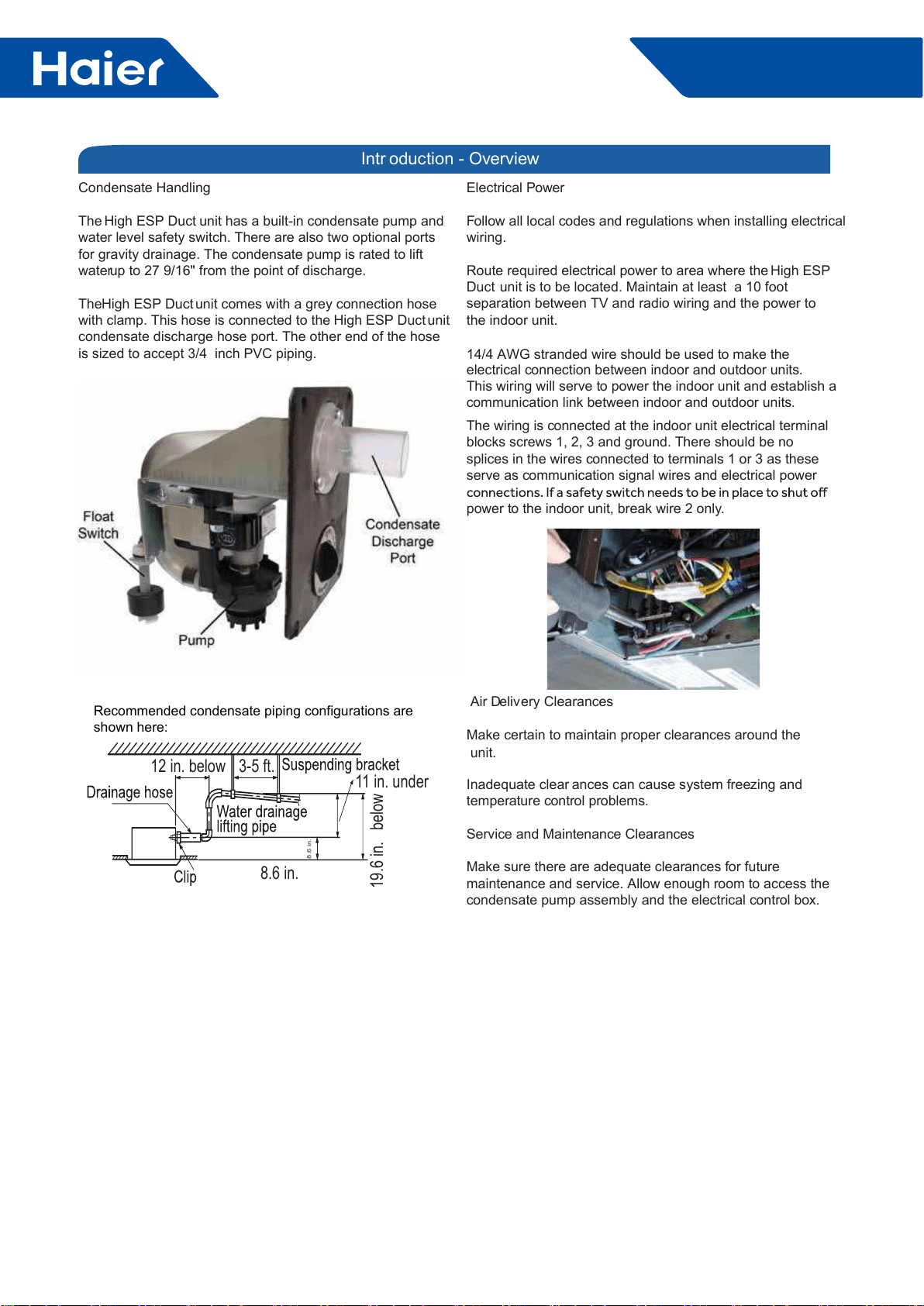
Air Delivery Clearances
Make certain to maintain proper clearances around the
unit.
Inadequate clear ances can cause system freezing and
temperature control problems.
Service and Maintenance Clearances
Make sure there are adequate clearances for future
maintenance and service. Allow enough room to access the
condensate pump assembly and the electrical control box.
Electrical Power
Follow all local codes and regulations when installing electrical
wiring.
Route required electrical power to area where the High ESP
Duct unit is to be located. Maintain at least a 10 foot
separation between TV and radio wiring and the power to
the indoor unit.
14/4 AWG stranded wire should be used to make the
electrical connection between indoor and outdoor units.
This wiring will serve to power the indoor unit and establish a
communication link between indoor and outdoor units.
The wiring is connected at the indoor unit electrical terminal
blocks screws 1, 2, 3 and ground. There should be no
splices in the wires connected to terminals 1 or 3 as these
serve as communication signal wires and electrical power
power to the indoor unit, break wire 2 only.
Condensate Handling
The High ESP Duct unit has a built-in condensate pump and
water level safety switch. There are also two optional ports
for gravity drainage. The condensate pump is rated to lift
water up to 27 9/16" from the point of discharge.
The High ESP Duct unit comes with a grey connection hose
with clamp. This hose is connected to the High ESP Duct unit
condensate discharge hose port. The other end of the hose
is sized to accept 3/4 inch PVC piping.
Intr oduction - Overview
12 in. below 3-5 ft. 11 in. under
8.6 in.
8.6 in.
19.6 in. below
Recommended condensate piping configurations are
shown here:

47
FlexFit Pro
ENGLISH
Procedure for Selecting the LocationRequired Tools for Installation
• Drill
• Wire Snipper
• Hole Saw 2 3/4”
• Vacuum pump
• Soap-and-water solution or gas leakage
detector
• Torque wrench
• 17mm, 22mm, 26mm
• Tubing cutter
• Flaring tool
• Razor knife
• Measuring tape
• Level
• Micron gauge
• Nitrogen
• Mini-Split AD-87 Adapter (1/4” to 5/16”)
• A - Non-adhesive Tape
• B - Adhesive Tape
• C - Saddle (L.S.) with screws
• D - Electrical wiring
• E - Drain hose (Included)
• F - Insulation
• G - Piping hole cover (Included)
Note:
1) R-410A refrigerant is a safe, nontoxic
if there is a concern about a dangerous
level of refrigerant concentration in the
case of refrigerant leakage, add extra
ventilation.
where you have enough space to position
the unit.
• Place where the drainage pipe can be
properly positioned.
• Place where the inlet and outlet air of the
indoor unit will not be blocked.
• Do not install the unit in a place with
heavy oil or moisture (e.g. - kitchens and
workshops)
• Do not install in a location with
destructive gas (such as sulfuric acid gas)
or pungent gas (thinner and gasoline) are
used or stored.
• Choose a place solid enough to bear the
weight and vibration of the unit and where
• Install where there are no expensive
items like a television or piano below the
indoor unit.
• Leave enough space for maintenance.
• Install at least 3 ft. away from televisions
and radios to avoid interference.
Threaded Rod Mounting Information
The High ESP Duct unit should be mounted to the
building structure using threaded rods. The threaded
rods should have washers and nuts to allow the height
and level of the High ESP Duct unit to be adjusted.
items. The materials required for mounting to the brackets
include:
4- 3/8” Threaded Rods
4- Mounting Brackets
Washers
Nuts (Double nut the assembly as shown in step 2.3)
Step 1 - Preparation
48
FlexFit Pro
ENGLISHSECTION D
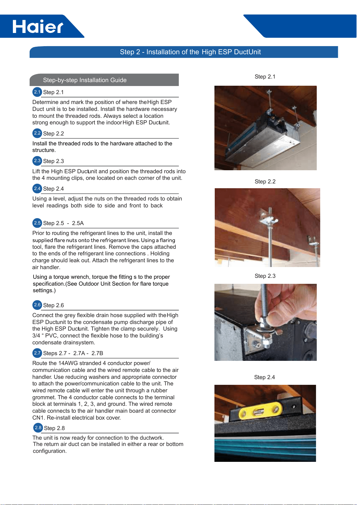
Step-by-step Installation Guide
2.1 Step 2.1
Determine and mark the position of where the High ESP
Duct unit is to be installed. Install the hardware necessary
to mount the threaded rods. Always select a location
strong enough to support the indoor High ESP Duct unit.
2.2 Step 2.2
Install the threaded rods to the hardware attached to the
structure.
2.3 Step 2.3
Lift the High ESP Duct unit and position the threaded rods into
the 4 mounting clips, one located on each corner of the unit.
2.4 Step 2.4
Using a level, adjust the nuts on the threaded rods to obtain
level readings both side to side and front to back
2.5 Step 2.5 - 2.5A
Prior to routing the refrigerant lines to the unit, install the
tool, flare the refrigerant lines. Remove the caps attached
to the ends of the refrigerant line connections . Holding
charge should leak out. Attach the refrigerant lines to the
air handler.
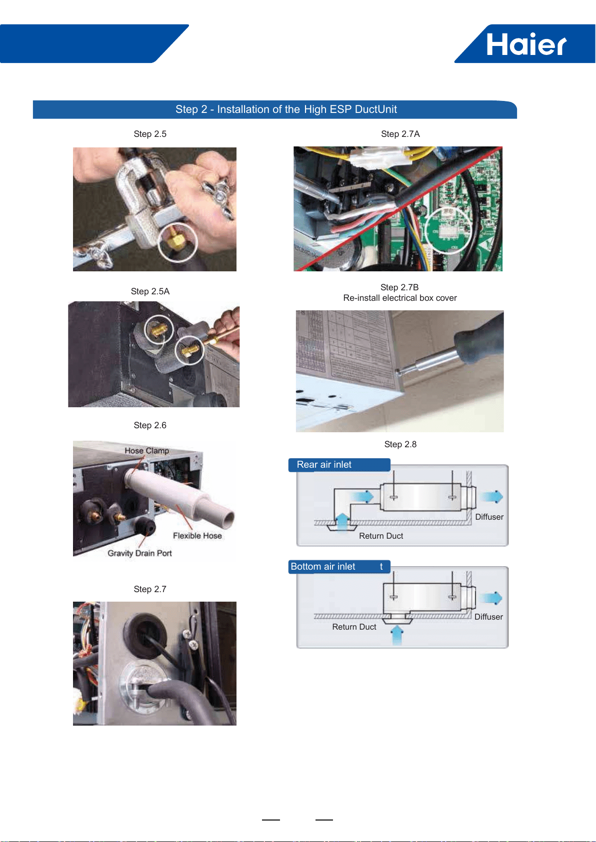
2.6 Step 2.6
Connect the grey flexible drain hose supplied with the High
ESP Duct unit to the condensate pump discharge pipe of
the High ESP Duct unit. Tighten the clamp securely. Using
3/4 “ PVC, connect the flexible hose to the building’s
condensate drain system.
2.7 Steps 2.7 - 2.7A - 2.7B
Route the 14AWG stranded 4 conductor power/
communication cable and the wired remote cable to the air
handler. Use reducing washers and appropriate connector
to attach the power/communication cable to the unit. The
wired remote cable will enter the unit through a rubber
grommet. The 4 conductor cable connects to the terminal
block at terminals 1, 2, 3, and ground. The wired remote
cable connects to the air handler main board at connector
CN1. Re-install electrical box cover.
The unit is now ready for connection to the ductwork.
The return air duct can be installed in either a rear or bottom
configuration.
Step 2.1
Step 2.3
Step 2.2
Step 2.4
2.8 Step 2.8
Step 2 - Installation of the High ESP Duct Unit
2.6
Using a torque wrench, torque the fitting s to the proper
specification.(See Outdoor Unit Section for flare torque
settings.)
49
FlexFit Pro
ENGLISH SECTION D
Step 2.5A
Step 2.7
Step 2.5
Step 2.6
Step 2.7A
Step 2.8
Rear air inlet
Bottom air inlet t
Diffuser
Return Duct
Diffuser
Return Duct
Step 2.7B
Re-install electrical box cover
Step 2 - Installation of the High ESP Duct Unit
FlexFit Pro
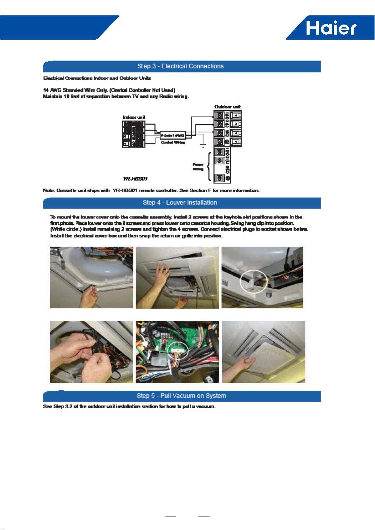
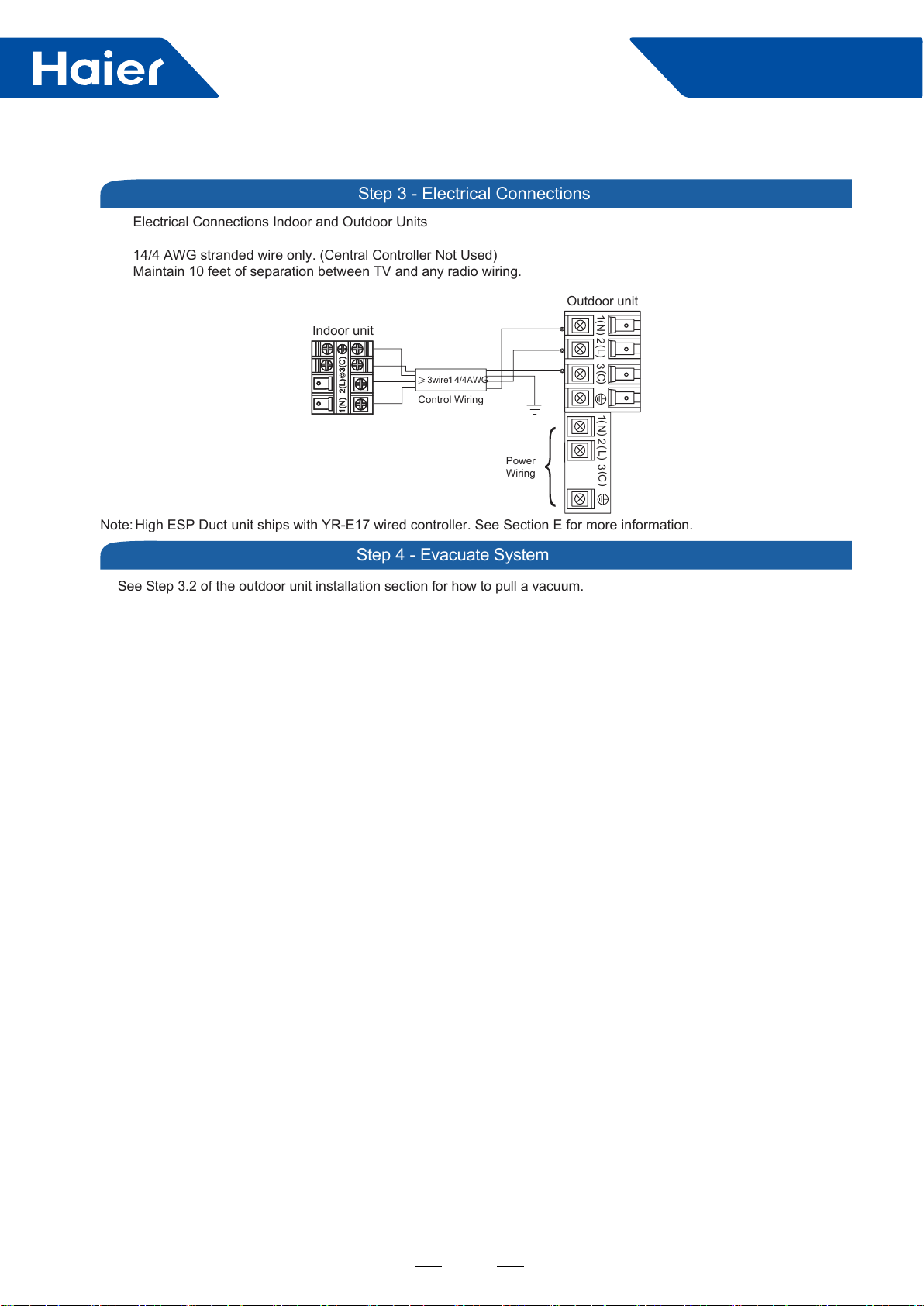
See Step 3.2 of the outdoor unit installation section for how to pull a vacuum.
Electrical Connections Indoor and Outdoor Units
14/4 AWG stranded wire only. (Central Controller Not Used)
Maintain 10 feet of separation between TV and any radio wiring.
Step 3 - Electrical Connections
Step 4 - Evacuate System
Outdoor unit
3
2
Power
Wiring
1)
(N)
(L )
(C3
2
1)
(N)
(L)
(C
Indoor unit
3wire
14
/4AWG
Control Wiring
Note: High ESP Duct unit ships with YR-E17 wired controller. See Section E for more information.
50

49
FlexFit Pro
Part 5 Outdoor Units
....................................................................................................................................................50
2. Dimensions ........................................................................................................................................................53
3. Piping ...............................................................................................................................................................55
4. Wiring diagrams ................................................................................................................................................55
5. Installation .........................................................................................................................................................58
50
FlexFit Pro
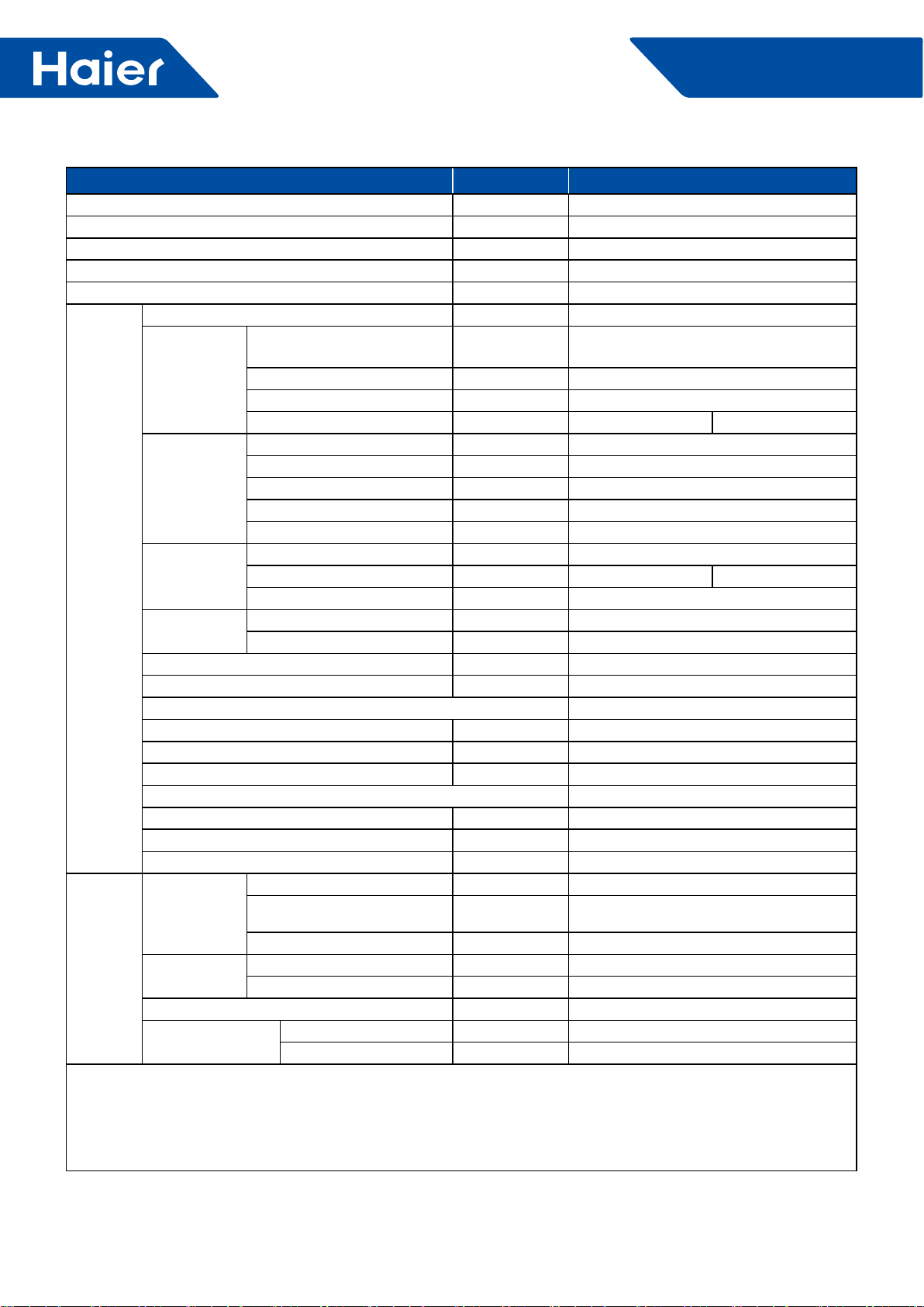
1. Specications
Item Model 1U24LP2VHA
Power cable H05RN-F 3G 4.0mm2
Communication cable/Connecting cable H05RN-F 4G 2.5mm2
Power source N, V, Hz 1PH, 220-240V~, 50/60Hz
Start current A 3
Outdoor
unit
Unit model (color) 1U24LP2VHA (WHITE)
Compressor
Model/Manufacture/
place TNB220FFEMC
Oil model FV50S
Oil charging CC 520
Type Rotary
Fan
Type×Number Axial×1
Speed r/min 650/600/500/400/300/200
Fan motor output/input
power kW 100/120
Air-ow (H-M-L) m3/h 3200
Coil
Type/Diameter mm TP2M/Φ7 wide n
Row/Fin pitch 2 1.65
Total area m2/
Dimensions External (L×M×H) mm×mm×mm 965*950*370
Package (L×M×H) mm×mm×mm 1095*1050*450
Drainage pipe (material, I.D./O.D.) mm None
Refrigerant control method mm/mm 2.2mm electronic expansion valve
Defrosting Auto
Volume of accumulator L 2.1
Sound power noise level (H-M-L) dB (A) 64
Sound pressure noise level (H-M-L) dB (A) 47
Type of four way valve SHF-4-10A
Insulation material Felt
Crankcase heater power W /
Weight (Net/Shipping) kg/kg 80/92
Piping
Refrigerant Type/Charge g R410A/2500
Recharge quantity g/m 45
Pipe Liquid mm 9.52
Gas mm 15.88
Connecting method Flared
Between I.D &O.D
MAX. Drop m 30
MAX. Piping length m 50
Maximum pipe length
without recharge
refrigerant m 20
Working
temp.
Cooling (Min-Max) °C -15~50
Heating (Min-Max) °C -20~24
Norminal condition:
Indoor temperature (cooling) : 80.6DB (°F)/66WB (°C) , Indoor temperature (heating) : 68DB (°F)
Outdoor temperature (cooling) : 95DB (°F)/75WB (°F) , Outdoor temperature (heating) : 44.6DB (°F)/42.8WB (°F)
The noise level will be measured in the third octave band limited values, using a Real Time Analyzer calibrated
sound intensity meter. It is a sound pressure noise level.
51
FlexFit Pro
Item Model 1U36LP2VHA
Power cable H05RN-F 3G 4.0mm2
Communication cable/Connecting cable H05RN-F 4G 2.5mm2
Power source N, V, Hz 1PH, 220-240V~, 50/60Hz
Start current A 3
Outdoor
unit
Unit model (color) 1U36LP2VHA (WHITE)
Compressor
Model/Manufacture/
place TNB306FPPMC
Oil model FV50S
Oil charging CC 870
Type Rotary
Fan
Type×Number Axial×1
Speed r/min 750/700/650/600/500/400/300
Fan motor output/input
power kW 100/120
Air-ow (H-M-L) m3/h 4000
Coil
Type/Diameter mm TP2M/Φ7 wide n
Row/Fin pitch 2 1.65
Total area m2/
Dimensions External (L×M×H) mm×mm×mm 965*950*370
Package (L×M×H) mm×mm×mm 1095*1050*450
Drainage pipe (material, I.D./O.D.) mm None
Refrigerant control method mm/mm 2.2mm electronic expansion valve
Defrosting Auto
Volume of accumulator L 2.1
Sound power noise level (H-M-L) dB (A) 68
Sound pressure noise level (H-M-L) dB (A) 52
Type of four way valve SHF-4-10A
Insulation material Felt
Crankcase heater power W /
Weight (Net/Shipping) kg/kg 82/94
Piping
Refrigerant Type/Charge g R410A/2500
Recharge quantity g/m 45
Pipe Liquid mm 9.52
Gas mm 15.88
Connecting method Flared
Between I.D &O.D
MAX. Drop m 30
MAX. Piping length m 50
Maximum pipe length
without recharge
refrigerant m 20
Working
temp.
Cooling (Min-Max) °C -15~50
Heating (Min-Max) °C -20~24
Norminal condition:
Indoor temperature (cooling) : 80.6DB (°F)/66WB (°C) , Indoor temperature (heating) : 68DB (°F)
Outdoor temperature (cooling) : 95DB (°F)/75WB (°F) , Outdoor temperature (heating) : 44.6DB (°F)/42.8WB (°F)
The noise level will be measured in the third octave band limited values, using a Real Time Analyzer calibrated
sound intensity meter. It is a sound pressure noise level.
52
FlexFit Pro
Item Model 1U48LP2VHA
Power cable H05RN-F 5G 2.5mm2
Communication cable /
Connecting cable H05RN-F 4G 2.5mm2
Power source N, V, Hz 3N~, 380~415, 50/60Hz
Start current A 3
Outdoor
unit
Unit model (color) 1U48LP2VHA
Compressor
Model/Manufacture/place MNB42FFAMC-L (MITSUBISHI
ELECTRIC COMPRESSOR CO., LTD)
Oil model PVE (FV50S)
Oil charging CC 1600
Type Twin Rotary 1
Fan
Type×Number Axial×2
Speed r/min 700±40
Fan motor input power kW 0.12×2
Fan motor output power kW 0.10×2
Air-ow (H-M-L) m3/h 7000
Coil
Type/Diameter mm TP2M/Φ7.0
Row/Fin pitch 2 1.4
Total area m21.17
Dimensions External (W×D×H) mm×mm×mm 950×370×1350
Package (W×D×H) mm×mm×mm 1090×480×1500
Drainage pipe (material, I.D./O.D.) mm None
Refrigerant control method mm/mm ELECTRONIC VAVE 3.0mm
Defrosting Auto
Volume of accumulator L 4.0
Sound power Noise level (H-M-L) dB (A) 70
Sound pressure Noise level (H-M-L) dB (A) 53
Type of four way valve SHF-20D-46
Insulation material XPE
Crankcase heater power W 38
Weight (Net/Shipping) kg/kg 108/121
Piping
Refrigerant
Type/Charge g R410A/3700
Maximum pipe length
without recharge refrigerant 30
Recharge quantity g/m 45
Pipe Liquid mm 9.52
Gas mm 15.88
Connecting method Flared
Between I.D &O.D MAX. Drop m 30
MAX. Piping length m 75
Norminal condition:
Indoor temperature (cooling) : 80.6DB (°F)/66WB (°C) , Indoor temperature (heating) : 68DB (°F)
Outdoor temperature (cooling) : 95DB (°F)/75WB (°F) , Outdoor temperature (heating) : 44.6DB (°F)/42.8WB (°F)
The noise level will be measured in the third octave band limited values, using a Real Time Analyzer calibrated
sound intensity meter. It is a sound pressure noise level.
53
FlexFit Pro
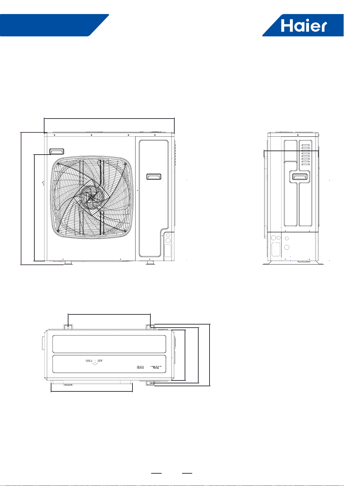
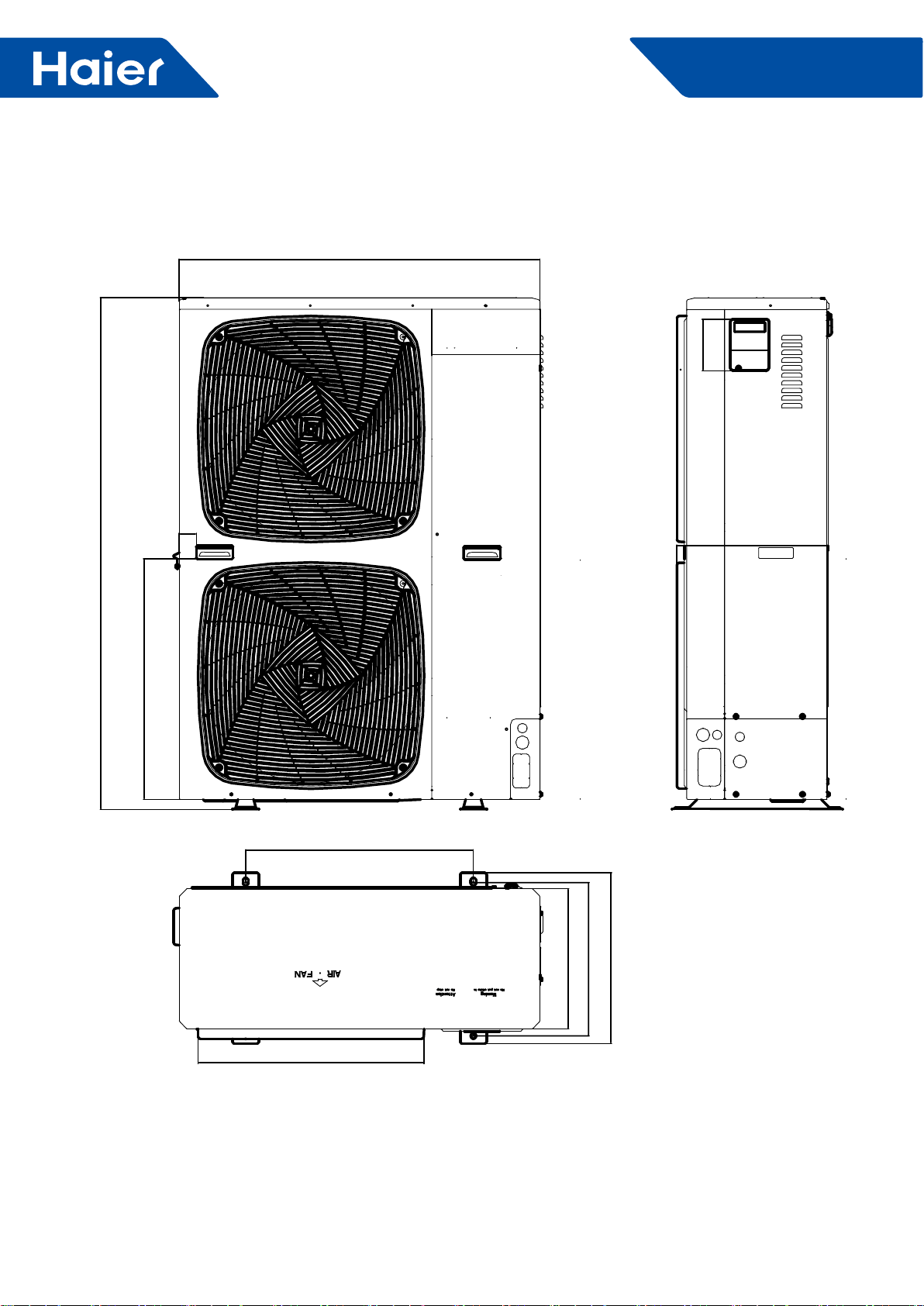
2. Dimensions
1U24LP2VHA 1U36LP2VHA
38(967)
30 5/8(778)
15 5/8(396)
23 5/8(600)
14 5/8(370)
15 7/8(404)
21 1/4(450)
23 1/2(596)
37 3/8(950)
54
FlexFit Pro
1U48LP2VHA
15 5/8(396)
102
11 3/16(285)
15 7/8(404)
17 11/16(450)
23 5/8(600)
14 5/8(370)
595
45
24 7/8(632)
136
37 3/8(950)
53 1/8(1350)
55
FlexFit Pro
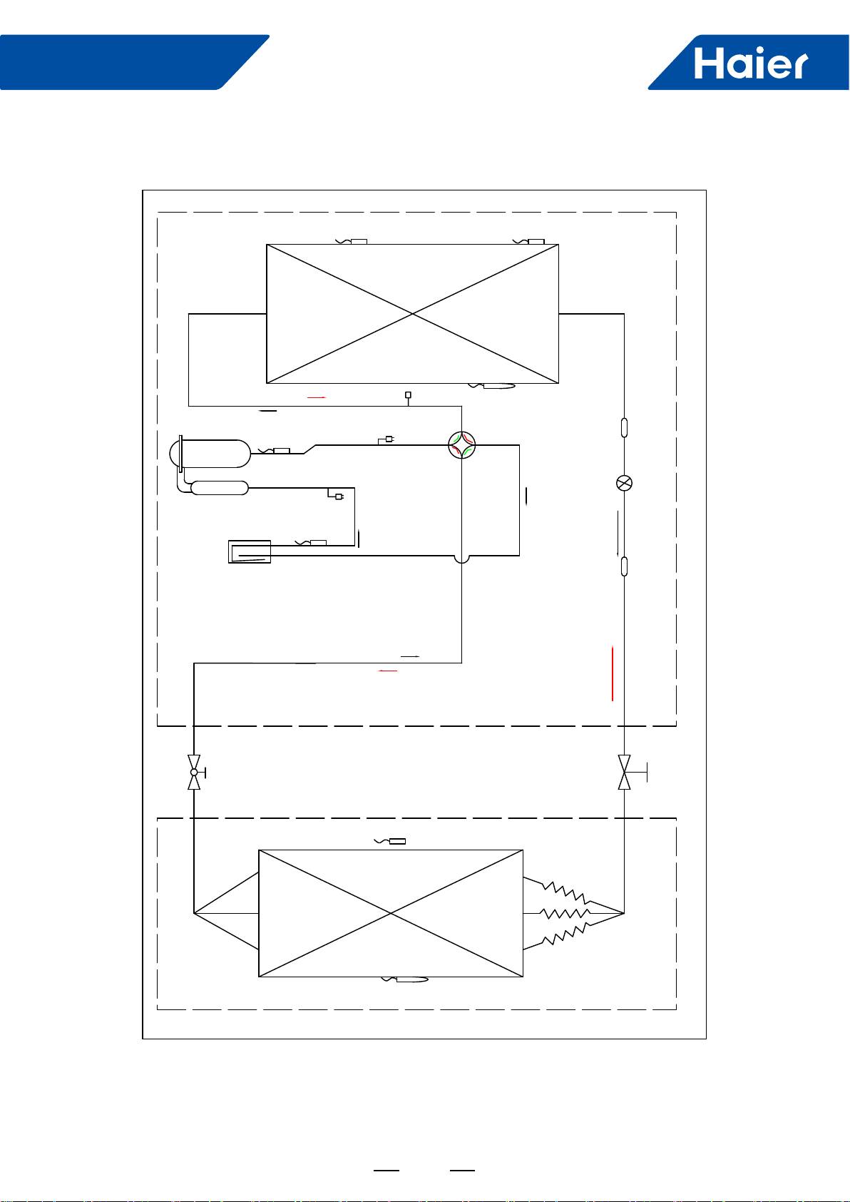
3. Piping
Cooling Heating
High pressure switch
Low pressure switch
EEV Filter
Sunction temp.sensor Ts
Discharging temp.sensor Td
Indoor coil temp.sensor Tc
Condensor middle
temp.sensor Tcm
Evaporate
Condensor
Stop valve
( gas side)
3- way stop
valve( liquid side)
4- way stop valve
Liquid -gas segerator
Filter
Defrosting temp.sensor Te
Heater
Indoor ambient temp.sensor Tai
Compressor
Outdoor ambient temp.
sensor Tai
Heating
Cooling
Heating
Cooling
Maintance valve
56
FlexFit Pro
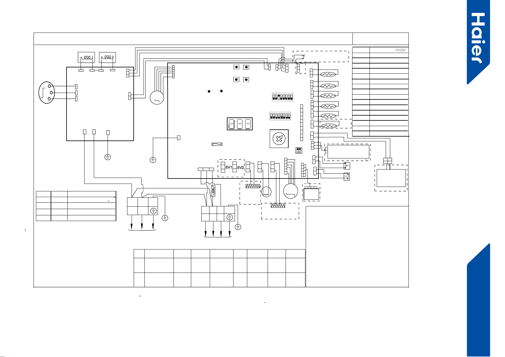
4. Wiring diagrams
1U36LP2VHA 1U36LP2VHA
CIRCUIT DIAGRAM OF OUTDOOR UNIT
***************************************************************
Tcm:Temperature sensor of condenser’s middle position
Ts:Compressor suction temperature sensor
Te: Defrost tempreature sensor
Tao:Outdoor unit ambient temperature sensor
Td:Compressor dischargetemperature sensor
Th:Temperature sensor of hot water(optional)
E.E.V:Electronic expansion valve
LP:Low pressure switch
HP:High pressure switch
DERD:Demand response enabling device
(Only used in
Australia and New Zealand area
)
***************************************************************
BLK:black WHT:white RD:red Y/G:yellow/green
Explanation of abbreviations 1:
0
1
2
3
SW 8 Definition
(
model
model
)
4
5
6
7
8
9
A
B
C
D
E
F
Reserved
Reserved
Reserved
Reserved
Reserved
Reserved
L
POWER SUPPLY
N
Y/G
BLU
BLK
W
U
COMPRESSOR
V
U
V
W
AC_L
AC_N
DRIVER
MODULE
L1
REACTOR2
CN605
L2 L2
FILTER&
L1
Y/G
1U24LP2VHA
LED1LED2
power
indicate
communication
indicate
T6.3A/250VAC
FUSE1
CN
2
DRED
CN
1
CN
14 CN10
CN23
CN
21
CN
5
CN
3
CN
4
C
N6
CN
7
CN24
CN
8
CN
18
CN13
M
DC FAN MOTOR 1
LED3
error&status indiate
ON
SW6
ON
4321
8765
CONTROL BOARD
0
F
E
D
C
B
A
9
8
7
6
5
4
3
2
1
SW8
S
W2
S
W3
S
W5
S
W4
MODE
UP
SET
DOWN
WHT
L
NSIG
M
E.E.V
CN19
SV1
CN17
SV2
CN20 CN16 CN9
RD
WHT
BLK
12V
GND
CN25
PWD
module
com1
C
N
15
C
N
11
module
com2
CN22
REACTOR1
Crankcase
heater
(CHTR) 4WV
Tcm
Td
Te
Ta
TS
TH
Reserved
Reserved
Reserved
SW7
ON
21
BLU:blue BRN:brown
SW1-1 SW1-2 SW1-3 SW1-4 SW1-5 SW1-6 SW1-7 SW1-8
ON
OFF
Manually
forced operation
valid
Manually
forced operation
invalid
Manually
forced
cooling
Manually
forced
heating
low stand
by power
cost
normal
stand by
cost
unit as
air conditi-
oner
central
control
Refrigerant
R410A
Defrost
automatic
Defrost
by time
Not for
base
station
GND
S
CN624
5V
BLK
GROUND
CN604
CN602
CN601
4WV:Four way valve
BMS:Building Management System
0150518179U
( SINGLE FAN
MODEL)
CON1
Y/G
2.SW6 is used for central control adress selection
refer to service manual to get more details
3.Once out of factory ,do not change the switches
of SW1,SW6,SW7,SW8 without technical guidence.
4.Can do the parameters checking work by button
switches SW2/SW3/SW4/SW5 and digital display
LED 3,refer to service manual to get more details.
5.For maintenance safety ,please operate after pow-
er supply cut off at least 3 minutes
LP
HP
A
B
C1 C2
RD
BRN
NOTE:
SW7-1
OFF OFF
OFF ON
ON OFF
ON ON
SW7-2 Definition
DERD test selcetion 0
DERD test selcetion 1
DERD test selcetion 2
DERD non-test selcetion
SW1
4321
8765
BLK
RD
WHT
TO INDOOR UNIT
1
2
Y/G
3
REACTOR3
CENTRAL
CONTROLLER
/③BMS DEVICE
Parameters monitor
adaptor /②
Hydro unit
①external dry contact
input(ON/OFF signal)
④Bottom heater
(BHTR)
⑥ water he-
ater or hea-
ting only
③
BMS ⑤Refriger
ant R32
⑦Base
station
application
1.Dashed parts are optional.marks①②③④
⑤⑥⑦are function in future.
Reserved
1U36LP2VHA
1U42LP2VHA
1U48LP2VHA
Reserved
Reserved
57
FlexFit Pro
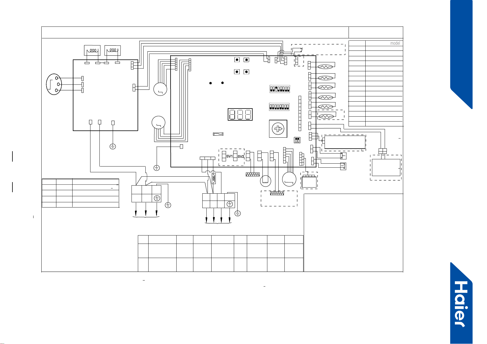
1U48LP2VHA
CIRCUIT DIAGRAM OF OUTDOOR UNIT
***************************************************************
Tcm:Temperature sensor of condenser’s middle position
Ts:Compressor suction temperature sensor
Te: Defrost tempreature sensor
Tao:Outdoor unit ambient temperature sensor
Td:Compressor dischargetemperature sensor
Th:Temperature sensor of hot water(optional)
E.E.V:Electronic expansion valve
LP:Low pressure switch
HP:High pressure switch
DERD:Demand response enabling device
(Only used in
Australia and New Zealand area
)
***************************************************************
BLK:black WHT:white RD:red Y/G:yellow/green
Explanation of abbreviations 1:
0
1
2
3
SW 8 Definition
(
model
model
)
4
5
6
7
8
9
A
B
C
D
E
F
Reserved
Reserved
Reserved
Reserved
Reserved
Reserved
L
POWER SUPPLY
N
Y/G
BLU
BLK
W
U
COMPRESSOR
V
U
V
W
AC_L
AC_N
DRIVER
MODULE
L1
REACTOR2
CN605
L2 L2
FILTER&
L1
Y/G
LED1LED2
power
indicate
communication
indicate
T6.3A/250VAC
FU
SE1
CN
2
DRED
CN
1
CN
14 CN10
CN23
CN
21
CN
5
CN
3
CN
4
C
N6
CN
7
CN24
CN
8
CN
18
CN13
CN12
M
DC FAN MOTOR 1
M
DC FAN MOTOR 2
LED3
error&status indiate
SW1
ON
4321
8765
SW6
ON
4321
8765
CONTROLBOARD
0
F
E
D
C
B
A
9
8
7
6
5
4
3
2
1
SW8
S
W2
S
W3
S
W5
S
W4
MODE
UP
SET
DOWN
WHT
L
NSIG
M
E.E.V
CN19
SV1
CN17
SV2
CN20 CN16 CN9
RD
WHT
BLK
12V
GND
CN25
PWD
module
com1
C
N
15
C
N
11
module
com2
CN22
REACTOR1
④Bottom heater
(BHTR)
Crankcase
heater
(CHTR) 4WV
Tcm
Td
Te
Ta
TS
TH
CENTRAL
CONTROLLER
/③BMS DEVICE
Parameters monitor
adaptor /②
Hydro unit
LP
Reserved
SW7
ON
21
BLU:blue BRN:brown
1.Dashed parts are optional.marks①②③④
⑤⑥⑦are function in future.
2.SW6 is used for central control adress selection
refer to service manual to get more details
3.Once out of factory ,do not change the switches
of SW1,SW6,SW7,SW8 without technical guidence.
4.Can do the parameters checking work by button
switches SW2/SW3/SW4/SW5 and digital display
LED 3,refer to service manual to get more details.
5.For maintenance safety ,please operate after pow-
er supply cut off at least 3 minutes
SW1-1 SW1-2 SW1-3 SW1-4 SW1-5 SW1-6 SW1-7 SW1-8
ON
OFF
Manually
forced operation
valid
Manually
forced operation
invalid
Manually
forced
cooling
Manually
forced
heating
low stand
by power
cost
normal
stand by
cost
unit as
air conditi-
oner
⑥ water he-
ater or hea-
ting only
③
BMS
central
control Refrigerant
R410A
⑤Refriger
ant R32
Defrost
automatic
Defrost
by time
Not for
base
station
⑦Base
station
application
NOTE:
SW7-1
OFF OFF
OFF ON
ON OFF
ON ON
SW7-2
Definition
DERD test selcetion 0
DERD test selcetion 1
DERD test selcetion 2
DERD non-test selcetion
①external dry contact
input(ON/OFF signal)
GND
S
CN624
5V
BLK
GROUND
CN604
CN602
CN601
4WV:Four way valve
BMS:Building Management System
0150516939U
( UPPER MOTOR )
( LOWER MOTOR)
CON1
Y/G
HP
A
B
C1 C2
RD
BRN
BLK
RD
WHT
TO INDOOR UNIT
1
2
Y/G
3
REACTOR3
1U24LP2VHA
Reserved
Reserved
1U36LP2VHA
1U42LP2VHA
1U48LP2VHA
Reserved
Reserved
Reserved
58
FlexFit Pro
5. Installation
ENGLISH SECTION A
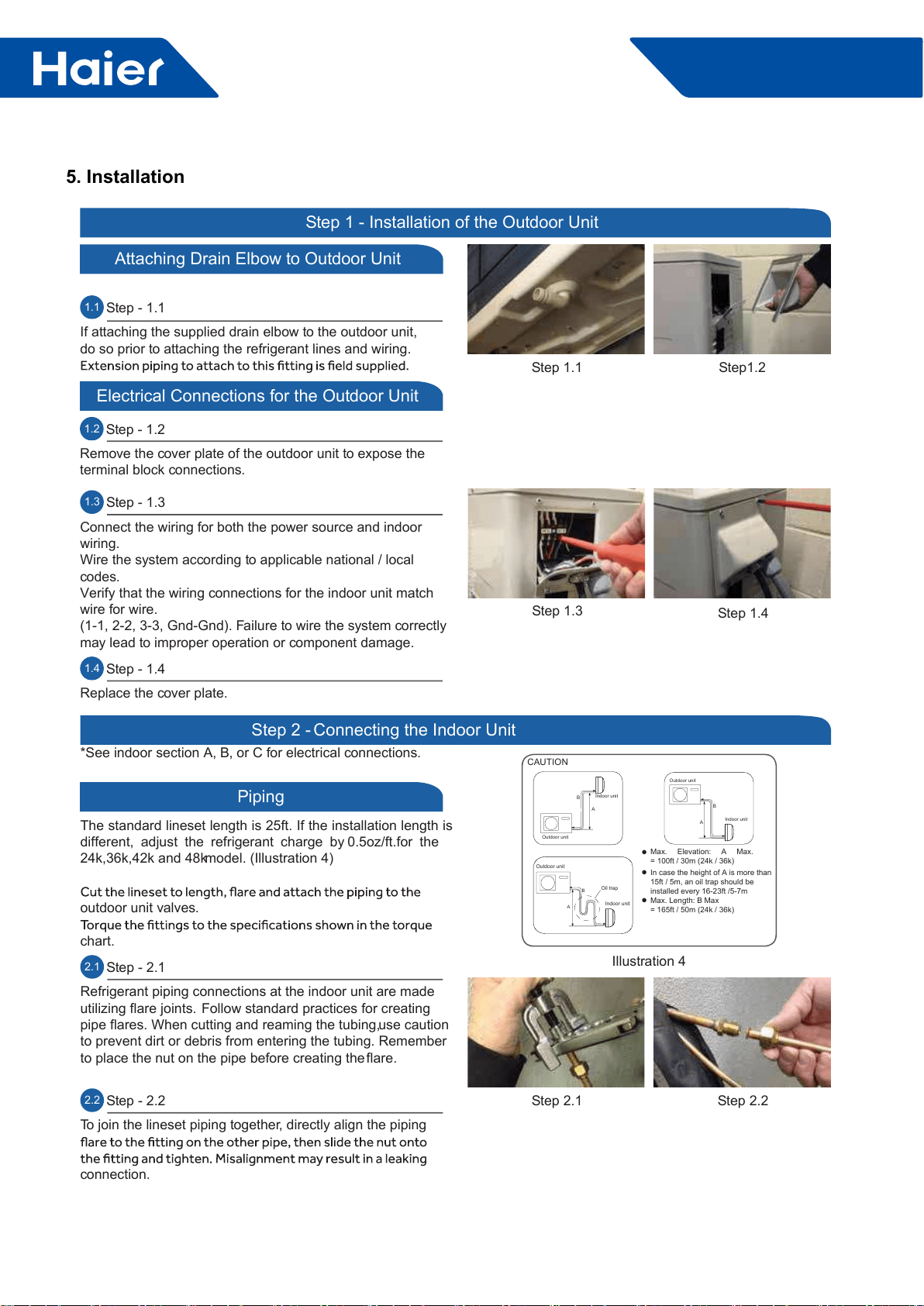
1.1 Step - 1.1
If attaching the supplied drain elbow to the outdoor unit,
do so prior to attaching the refrigerant lines and wiring.
Step1.2
Step 1.1
Step 1 - Installation of the Outdoor Unit
Attaching Drain Elbow to Outdoor Unit
1.2 Step - 1.2
Remove the cover plate of the outdoor unit to expose the
terminal block connections.
Electrical Connections for the Outdoor Unit
Step 1.3 Step 1.4
1.3 Step - 1.3
Connect the wiring for both the power source and indoor
wiring.
Wire the system according to applicable national / local
codes.
Verify that the wiring connections for the indoor unit match
wire for wire.
(1-1, 2-2, 3-3, Gnd-Gnd). Failure to wire the system correctly
may lead to improper operation or component damage.
1.4 Step - 1.4
Replace the cover plate.
Step 2.2Step 2.1
Outdoor unit
Indoor unit
A
B
Outdoor unit
Indoor unit
A
B
A
B
Outdoor unit
Indoor unit
Oil trap
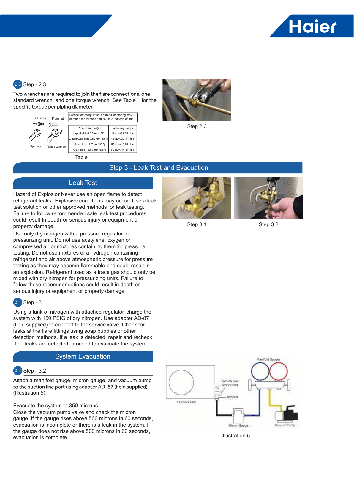
CAUTION
Max. Elevation: A Max.
= 100ft / 30m (24k / 36k)
In case the height of A is more than
15ft / 5m, an oil trap should be
installed every 16-23ft /5-7m
Max. Length: B Max
= 165ft / 50m (24k / 36k)
●
●
●
Illustration 4
Step 2 - Connecting the Indoor Unit
Piping
The standard lineset length is 25ft. If the installation length is
different, adjust the refrigerant charge by 0.5oz/ft.for the
24k,36k,42k and 48k model. (Illustration 4)
outdoor unit valves.
chart.
2.1 Step - 2.1
Refrigerant piping connections at the indoor unit are made
utilizing flare joints. Follow standard practices for creating
pipe flares. When cutting and reaming the tubing, use caution
to prevent dirt or debris from entering the tubing. Remember
to place the nut on the pipe before creating the flare.
2.2 Step - 2.2
To join the lineset piping together, directly align the piping
connection.
*See indoor section A, B, or C for electrical connections.
ǿ
59
FlexFit Pro
ENGLISH
Hazard of Explosion! Never use an open flame to detect
refrigerant leaks.. Explosive conditions may occur. Use a leak
test solution or other approved methods for leak testing.
Failure to follow recommended safe leak test procedures
could result In death or serious injury or equipment or
property damage.
Use only dry nitrogen with a pressure regulator for
pressurizing unit. Do not use acetylene, oxygen or
compressed air or mixtures containing them for pressure
testing. Do not use mixtures of a hydrogen containing
refrigerant and air above atmospheric pressure for pressure
testing as they may become flammable and could result in
an explosion. Refrigerant used as a trace gas should only be
mixed with dry nitrogen for pressurizing units. Failure to
follow these recommendations could result in death or
serious injury or equipment or property damage.
3.1 Step - 3.1
Using a tank of nitrogen with attached regulator, charge the
system with 150 PSIG of dry nitrogen. Use adapter AD-87
(field supplied) to connect to the service valve. Check for
leaks at the flare fittings using soap bubbles or other
detection methods. If a leak is detected, repair and recheck.
If no leaks are detected, proceed to evacuate the system.
Step 3.1 Step 3.2
Illustration 5
Leak Test
System Evacuation
Step 3 - Leak Test and Evacuation
3.2 Step - 3.2
Attach a manifold gauge, micron gauge, and vacuum pump
(Illustration 5)
Evacuate the system to 350 microns.
Close the vacuum pump valve and check the micron
gauge. If the gauge rises above 500 microns in 60 seconds,
evacuation is incomplete or there is a leak in the system. If
the gauge does not rise above 500 microns in 60 seconds,
evacuation is complete.
Step 2.3
Table 1
Half union Flare nut
Torque wrench
Spanner
Forced fastening without careful centering may
damage the threads and cause a leakage of gas.
Pipe Diameter(ǿ) Fastening torque
Liquidside6.35mm(1/4") 18N.m/13.3Ft.lbs
Liquid/Gas side9.52mm(3/8") 42 N.m/30.1Ft.lbs
Gas side 12.7mm(1/2") 55N.m/40.6Ft.lbs
Gas side 15.88mm(5/8") 60 N.m/44.3Ft.lbs
2.3 Step - 2.3
standard wrench, and one torque wrench. See Table 1 for the
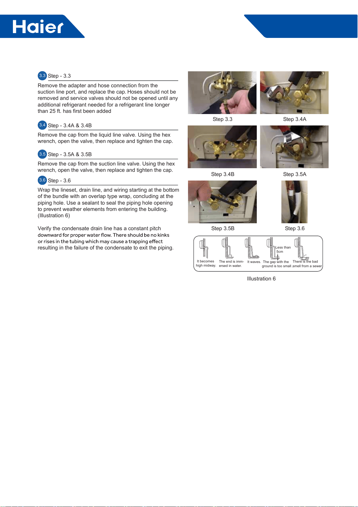
60
FlexFit Pro
ENGLISH
Step 3.3 Step 3.4A
Step 3.5A
Step 3.6
Step 3.4B
Step 3.5B
3.3 Step - 3.3
Remove the adapter and hose connection from the
suction line port, and replace the cap. Hoses should not be
removed and service valves should not be opened until any
additional refrigerant needed for a refrigerant line longer
than 25 ft. has first been added.
3.4 Step - 3.4A & 3.4B
Remove the cap from the liquid line valve. Using the hex
wrench, open the valve, then replace and tighten the cap.
Illustration 6
It becomes
high midway.
The gap with the
ground is too small
There is the bad
smell from a sewer
It waves.
The end is imm-
ersed in water.
Less than
5cm
3.5 Step - 3.5A & 3.5B
Remove the cap from the suction line valve. Using the hex
wrench, open the valve, then replace and tighten the cap.
3.6 Step - 3.6
Wrap the lineset, drain line, and wiring starting at the bottom
of the bundle with an overlap type wrap, concluding at the
piping hole. Use a sealant to seal the piping hole opening
to prevent weather elements from entering the building.
(Illustration 6)
Verify the condensate drain line has a constant pitch
resulting in the failure of the condensate to exit the piping.

61
FlexFit Pro
ENGLISH
Step 4 - Charging
See Steps 5.2 - 5.5 for evacuating the system prior to
charging. The standard lineset length is 25ft. If the
installation length is different, adjust the refrigerant charge
by 0.5.oz / ft. for the 24K, 36K and 48K model. (Step 4 -
Illustration 4)
Using the instruction manual, show the customer how to
properly use and care for the equipment.
by the Kyoto Protocol. Do not vent into the atmosphere.
Refrigerant type: R410A
GWP* value: 1975
GWP = global warming potential
• 1 the factory refrigerant charge of the product
• 1+2 the total refrigerant charge on the refrigerant charge
label supplied with the product.
product charging port (e.g. onto the inside of the stop valve
cover).
Kyoto Protocol
B - factory refrigerant charge of the product: see unit name
plate
D - total refrigerant charge
E - outdoor unit
F - refrigerant cylinder and manifold for charging
Refrigerant Charge Label
System Test
Check List
1
1+2= oz
R410A
2oz
2=
1=
B
C
D
F E
oz
A
Contains fluorinated greenhouse gases
covered by the Kyoto Protocol
Put check mark √ in boxes
No refrigerant leaks from line sets or other connections?
Are the linesets insulated properly?
Are the connecting wirings of indoor and outdoor firmly
inserted to the terminal block?
connected?
Is condensate draining correctly?
Is the indoor unit securely attached?
Is power source voltage correct according to local code?
Is there any noise?
Is the lamp normally lighting?
Are cooling and heating (when in heat pump) performing
normally?
Is the operation of room temperature sensor normal?
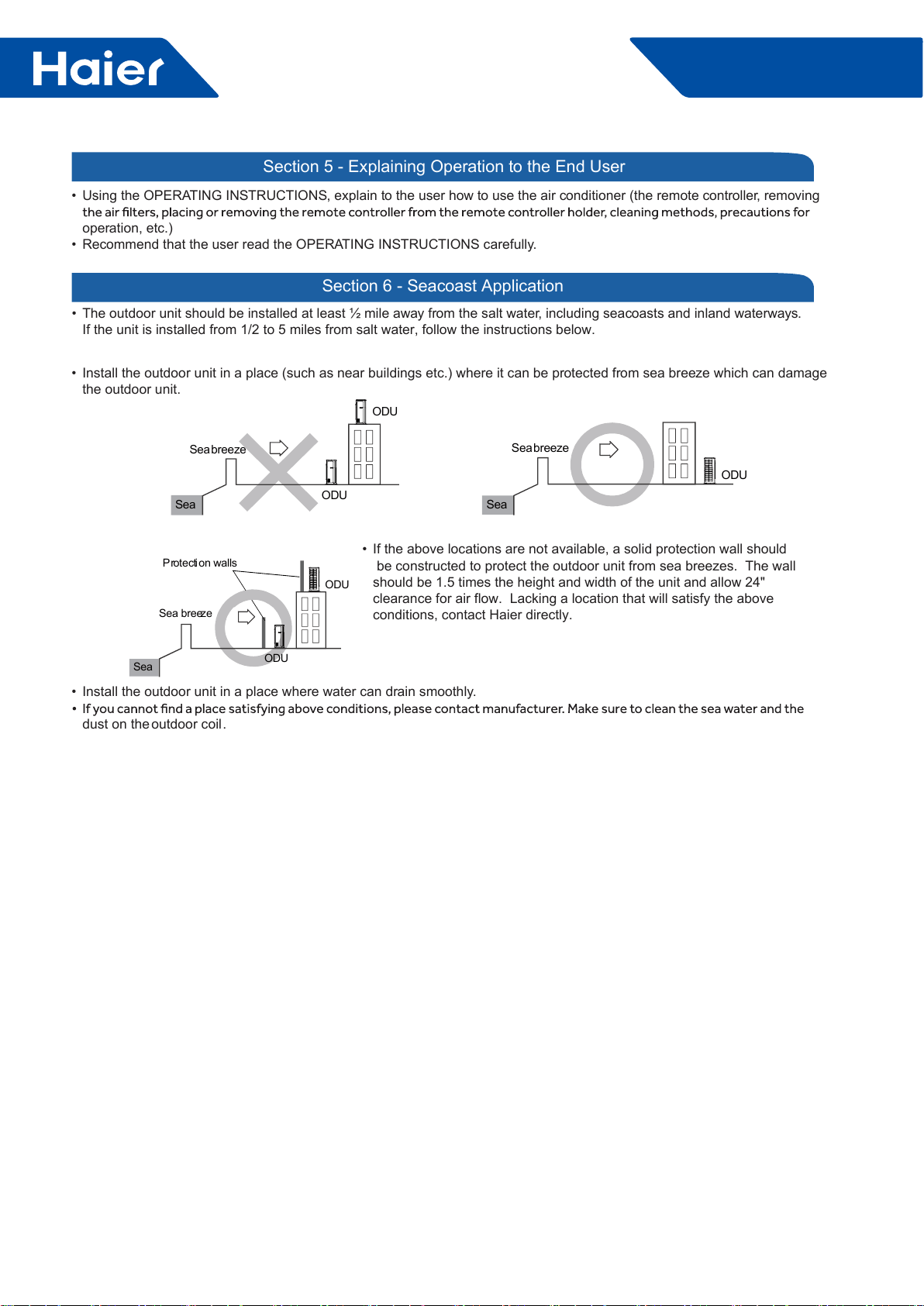
62
FlexFit Pro
• Using the OPERATING INSTRUCTIONS, explain to the user how to use the air conditioner (the remote controller, removing
operation, etc.)
• Recommend that the user read the OPERATING INSTRUCTIONS carefully.
Section 5 - Explaining Operation to the End User
Section 6 - Seacoast Application
• The outdoor unit should be installed at least ½ mile away from the salt water, including seacoasts and inland waterways.
If the unit is installed from 1/2 to 5 miles from salt water, follow the instructions below.
ODU
ODU
Seabreeze
Sea
ODU
Seabreeze
Sea
ODU
Sea breeze
Sea
Protection walls
ODU
• Install the outdoor unit in a place (such as near buildings etc.) where it can be protected from sea breeze which can damage
the outdoor unit.
• If the above locations are not available, a solid protection wall should
be constructed to protect the outdoor unit from sea breezes. The wall
should be 1.5 times the height and width of the unit and allow 24"
clearance for air flow. Lacking a location that will satisfy the above
conditions, contact Haier directly.
• Install the outdoor unit in a place where water can drain smoothly.
dust on the outdoor coil.

63
FlexFit Pro
Part 6 Controls and Troubleshooting
1. Indoor PCB ......................................................................................................................................................64
2. Indoor Dip Switches ..........................................................................................................................................65
3. Outdoor PCB .....................................................................................................................................................68
4. Error codes ........................................................................................................................................................70
5. Troubleshooting Error Codes ............................................................................................................................83
6. Functions ...........................................................................................................................................................92
7. Controllers .....................................................................................................................................................104
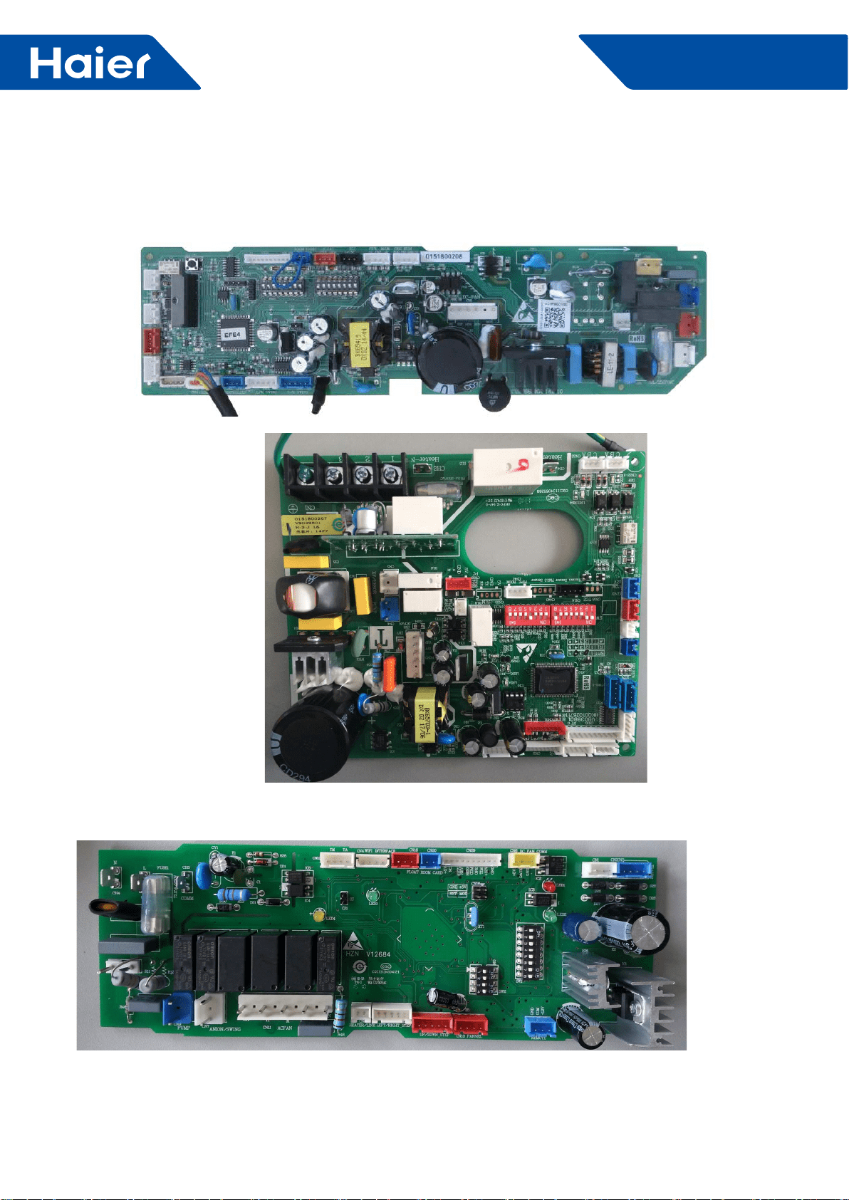
64
FlexFit Pro
1. Indoor PCB
1.1 AL24LP2VHA AL36LP2VHA AL48LP2VHA
PCB 0151800208
1.2 AM24LP2VHA
PCB 0151800267
1.3 AM36LP2VHA AM48LP2VHA
PCB 0151800106E
65
FlexFit Pro
2. Indoor Dip Switches
BM1 (1-ON, 0-OFF)
Capacity (SW1-1→SW1-3) Room card
SW1-4
Running
mode Unit Type Description
SW1-1 SW1-2 SW1-3 SW1-5 SW1-6 SW1-7 SW1-8
1 1 0 --- --- --- --- --- Capacity: 24kBTU(7.1kW)
0 0 1 --- --- --- --- --- Capacity: 30kBTU(9.0kW)
1 0 1 --- --- --- --- --- Capacity: 35kBTU(10.5kW)
0 1 1 --- --- --- --- --- Capacity: 42kBTU(12.5kW)
1 1 1 --- --- --- --- --- Capacity: 48kBTU(14.0kW_
--- --- --- 0 --- --- --- --- Room card invalid(default)
--- --- --- 1 --- --- --- --- Room card valid
--- --- --- --- 0 --- --- --- Heat pump(default)
--- --- --- --- 1 --- --- --- Cooling only
--- --- --- --- --- 0 0 1 High performance cassette
Settings as shipped
AL24LP2VHA AL36LP2VHA AL48LP2VHA :
PCB 0151800208
BM3-5 BM3-6 BM3-7 BM3-8
Indoor unit Address
(Indoor unit address for one wired
controller control more than one
unit)
OFF OFF OFF OFF 0 (master)
OFF OFF OFF ON 1(slave)
OFF OFF ON OFF 2(slave)
OFF OFF ON ON 3(slave)
OFF ON OFF OFF 4(slave)
OFF ON OFF ON 5(slave)
OFF ON ON OFF 6(slave)
OFF ON ON ON 7(slave)
ON OFF OFF OFF 8(slave)
ON OFF OFF ON 9(slave)
ON OFF ON OFF 10(slave)
ON OFF ON ON 11(slave)
ON ON OFF OFF 12(slave)
ON ON OFF ON 13(slave)
ON ON ON OFF 14(slave)
ON ON ON ON 15(slave)
Wired controller communication address
66
FlexFit Pro
AM24LP2VHA
PCB 0151800267
SW3-5 SW3-6 SW3-7 SW3-8
Indoor unit Address
(Indoor unit address for one wired
controller control more than one
unit)
OFF OFF OFF OFF 0 (master)
OFF OFF OFF ON 1(slave)
OFF OFF ON OFF 2(slave)
OFF OFF ON ON 3(slave)
OFF ON OFF OFF 4(slave)
OFF ON OFF ON 5(slave)
OFF ON ON OFF 6(slave)
OFF ON ON ON 7(slave)
ON OFF OFF OFF 8(slave)
ON OFF OFF ON 9(slave)
ON OFF ON OFF 10(slave)
ON OFF ON ON 11(slave)
ON ON OFF OFF 12(slave)
ON ON OFF ON 13(slave)
ON ON ON OFF 14(slave)
ON ON ON ON 15(slave)
Wired controller communication address
SW1-1 SW1-2 SW1-3 SW1-4 SW1-5 SW1-6 SW1-7 SW1-8 Description
1 1 0 --- --- --- --- --- AM24LP2VHA
--- --- --- 0 --- --- --- --- Room card invalid(default)
--- --- --- 1 --- --- --- --- Room card valid
--- --- --- --- 0 --- --- --- Cool and heat(default)
--- --- --- --- 1 --- --- --- Cool only
--- --- --- --- --- 0 --- --- External alarm output(default)
--- --- --- --- --- 1 --- --- Fresh air
--- --- --- --- --- --- 0 --- Without lter clean remind (default)
--- --- --- --- --- --- 1 --- With lter clean remind
--- --- --- --- --- --- --- 0 ESP DUCT ( USA)
--- --- --- --- --- --- --- 1 EU. &Australia
67
FlexFit Pro
BM1 (1-ON, 0-OFF)
Capacity (SW1-1→SW1-3) Room
card
SW1-4
Running
mode
SW1-5
Unit Type
SW1-1 SW1-2 SW1-3 SW1-6 SW1-7 SW1-8 Description
ON OFF ON --- --- --- --- --- AM36LP2VHA
ON ON ON --- --- --- --- --- AM48LP2VHA
--- --- --- ON --- --- --- --- Room card valid
--- --- --- OFF --- --- --- --- Room card invalid(default)
--- --- --- --- ON --- --- --- Cool only
--- --- --- --- OFF --- --- --- Cool and heat(default)
--- --- --- --- OFF ON OFF Medium ESP DUCT
--- --- --- --- ON ON OFF High ESP DUCT
AM36LP2VHA AM48LP2VHA PCB 0151800106E
SW2-1 SW2-2 SW2-3 SW2-4
Indoor unit Address
(Indoor unit address for one wired
controller control more than one
unit)
OFF OFF OFF OFF 0 (master)
OFF OFF OFF ON 1(slave)
OFF OFF ON OFF 2(slave)
OFF OFF ON ON 3(slave)
OFF ON OFF OFF 4(slave)
OFF ON OFF ON 5(slave)
OFF ON ON OFF 6(slave)
OFF ON ON ON 7(slave)
ON OFF OFF OFF 8(slave)
ON OFF OFF ON 9(slave)
ON OFF ON OFF 10(slave)
ON OFF ON ON 11(slave)
ON ON OFF OFF 12(slave)
ON ON OFF ON 13(slave)
ON ON ON OFF 14(slave)
ON ON ON ON 15(slave)
Wired controller communication address
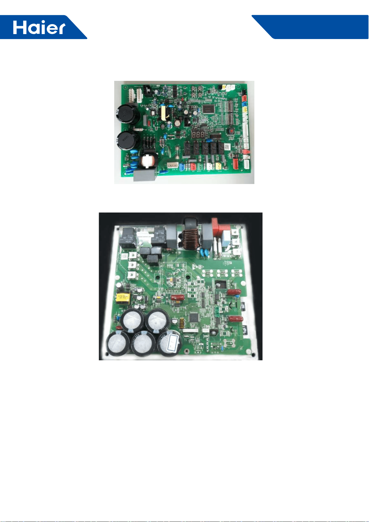
68
FlexFit Pro
3. Outdoor PCB
PCB: 0151800054B
Power module: 0150401824
69
FlexFit Pro
Outdoor Dip Switches
SW1-1 SW1-2 SW1-3 SW1-4 SW1-5 SW1-6 SW1-7 SW1-8 Description
OFF ---- ---- ---- ---- ---- ---- ---- Manually forced operation invalid(default)
ON ---- ---- ---- ---- ---- ---- ---- Manually forced operation valid
---- OFF ---- ---- ---- ---- ---- ---- Manually forced heating(default)
---- ON ---- ---- ---- ---- ---- ---- Manually forced cooling
---- ---- OFF ---- ---- ---- ---- ---- Normal standby cost(default)
---- ---- ON ---- ---- ---- ---- ---- Low stand by power cost
---- ---- ---- OFF ---- ---- ---- ---- Water heater or heating only
---- ---- ---- ON ---- ---- ---- ---- Unit as air conditioner (default)
---- ---- ---- ---- OFF ---- ---- ---- Central control(default)
---- ---- ---- ---- ON ---- ---- ---- BMS
---- ---- ---- ---- ---- OFF ---- ---- Refrigerant R410A(default)
---- ---- ---- ---- ---- ON ---- ---- Refrigerant R32
---- ---- ---- ---- ---- ---- OFF Defrost automatic(default)
---- ---- ---- ---- ---- ---- ON Defrost by time
---- ---- ---- ---- ---- ---- ---- OFF Not for base station
---- ---- ---- ---- ---- ---- ---- ON Base station application(default)
SW8: Dip switch setting
SW6 (1-ON, 0-OFF) Unit
address
for central
control
SW6-1 SW6-2 SW6-3 SW6-4 SW6-5 SW6-6 SW6-7 SW6-8
0 0 0 0 0 0 0 0 0
0 0 0 0 0 0 0 1 1
0 0 0 0 0 0 1 0 2
0 0 0 0 0 0 1 1 3
0 0 0 0 0 1 0 0 4
0 0 0 0 0 1 0 1 5
0 0 0 0 0 1 1 0 6
0 0 0 0 0 1 1 1 7
---- ---- ---- ---- ---- ---- ---- ---- ----
1 1 1 1 1 1 1 1 255
SW8 Denation
01U24LP2VHA
21U36LP2VHA
51U48LP2VHA
70
FlexFit Pro
4. Error Code
4.1 Failure code indoor unit
AL24LP2VHA AL36LP2VHA AL48LP2VHA
LED ash times of
indoor PCB LR.Recever
digital display Contents of malfunction Possible reasons
LED4 LED1
0 1 01 Malfunction of indoor unit ambient
temperature sensor
Sensor disconnected, broken, shorted,
or at wrong position.
0 2 02 Malfunction of indoor unit piping
temperature sensor
Sensor disconnected, broken, shorted,
or at wrong position.
0 4 04 PCB EEPROM error
EEPROM chip disconnected, broken,
or programmed incorrectly.
PCB defective.
0 7 07 Abnormal communication between
indoor and outdoor units
Poor wiring connections, faulty wiring,
poor power supply, incorrect addressing
of indoor units, malfunction of slave unit
programming in MAXI system; faulty
PCB.
0 8 08
Abnormal communication between
wired controller (or IR reciever) and
indoor unit
Wrong connection or wired controller
broken, or PCB faulty
0 12 0C Malfunction of drain system
Condensate pump disconnected
or faulty, oat switch a wrong
position, disconnected or faulty, or a
disconnection of the short circuit bridge
0 13 0D Zero cross sigal wrong Zero cross signal not detected
0 14 0E Indoor unit DC fan motor abnormal Fan motor disconnected, faulty wiring,
motor failure, or faulty circuit to motor
Note:
1. The outdoor failure can also be indicated by the indoor unit, the checking method as follows: If the outdoorerror
code is M (DECIMAL) , the indoor unit's I.R. receiver display will show the after converted hexadecimal code of
"M+20" (DECIMAL) , for example, if the outdoor error code is 2, the indoor unit I.R. receiver display will ash the
error code 16 (2→2+20=22→change deciaml 22 to hexadecimal code, get 16)
2. LED4 is a red one on the indoor PCB, LED1 is a yellow one.
3. To get much more details about the out door unit failure, please refer to the outdoor unit trouble shooting list.
71
FlexFit Pro
Large Cassette Error Code Logic
Cassette panel IR
receiver digital display
(ashing)
Corresponds to
outdoor error
code Description of malfunction Remarks
01 / Malfunction of indoor unit ambient temperature sensor
Malfunction of indoor
unit.
Refer to indoor unit
trouble shooting
list to get more
details
02 / Malfunction of indoor unit piping temperature sensor
04 / PCB EEPROM failure
07 / Abnormal communication between indoor and outdoor
units
08 / Abnormal communication between wired controller(or
I.R .RECEIVER) and indoor unit
0C / Malfunction of drain system(oat switch open circuit)
0D / Indoor unit Zero cross signal error
0E / Indoor unit DC fan motor abnormal
15 1 Outdoor main control PCB EEPROM malfunction
Malfunction of
outdoor unit.
Refer to outdoor unit
troubleshooting
list for more details
16 2 PIM(power intelligent module)hardware overcurrent
17 3 Compressor over current during deceleration
18 4 Communication abnormal between control
board and compressor driver module
19 5 Compressor overcurrent detected by control board
1A 6 DC voltage or AC voltage high
1B 7 Compressor current sampling circuit fault
1C 8 Discharge temperature too high
1D 9 DC fan motor fault
1E 10 Outdoor defrosting temp. sensor Te abnormal
1F 11 Suction temp. sensor Ts abnormal
20 12 Outdoor ambient temp. sensor Ta abnormal
21 13 Discharging temp. sensor Td abnormal
22 14 PFC circuit loop high voltage
23 15 Communication abnormal between indoor unit and
outdoor unit
24 16 Restriction in discharge piping
25 17 4-way valve abnormal
26 18 Compressor motor desynchronizing
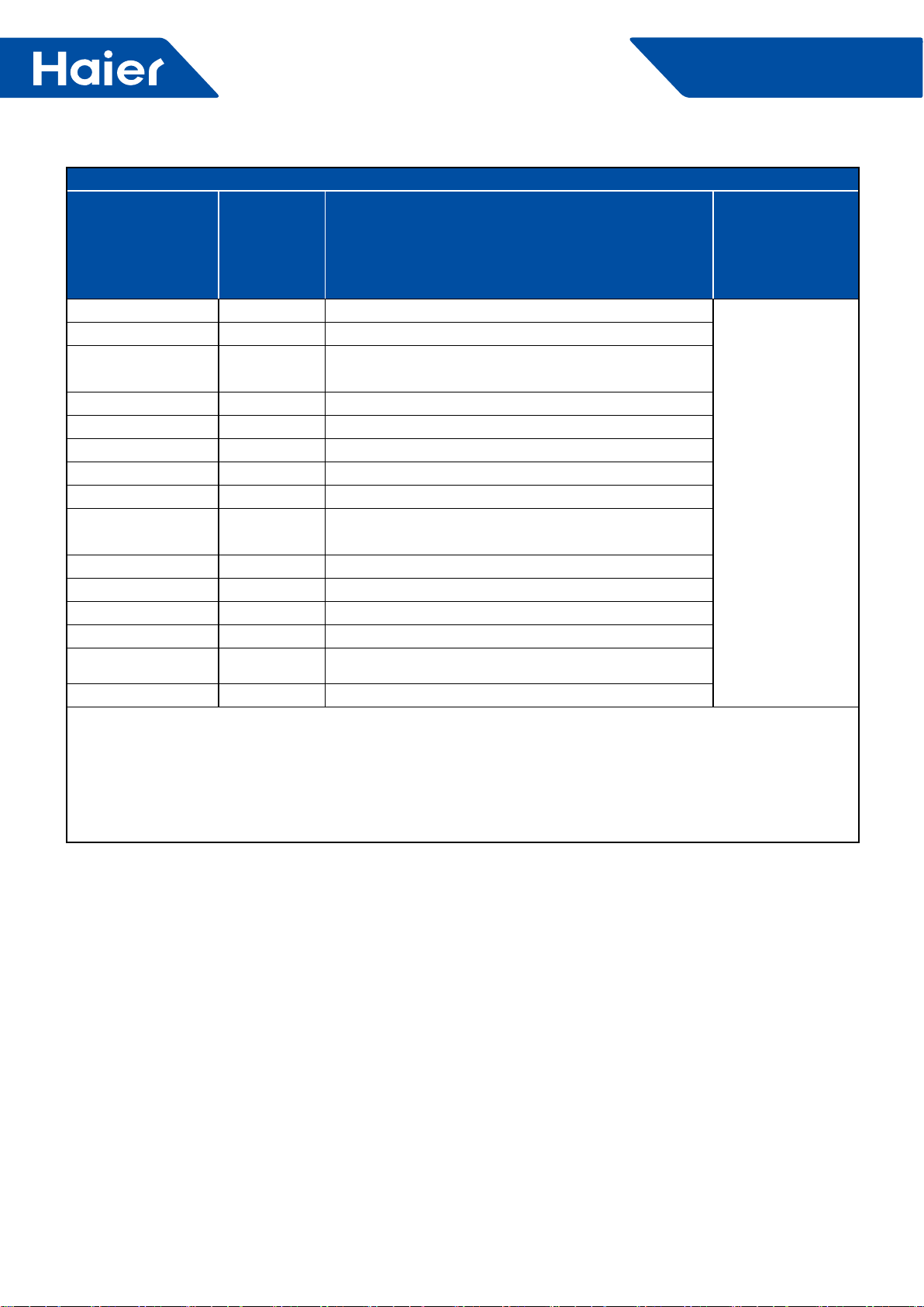
72
FlexFit Pro
Large Cassette Error Code Logic
Cassette panel IR
receiver digital display
(ashing)
Corresponds to
outdoor error
code Description of malfunction Remarks
28 20 Indoor pipe temperature too high
Malfunction of
outdoor unit.
Refer to outdoor unit
troubleshooting
list for more details
2A 22 PFC circuit loop overcurrent
2B 23 Temperature too high for compressor driver module
2C 24 Compressor start failure
2D 25 Input overcurrent of the drive module
2E 26 Lack phase of the drive module power supply
2F 27 Input current sampling circuit fault
30 28 No wiring of the compressor
39 37 Compressor overcurrent detected by
compressor driver module
3A 38 Drive module’s ambient temp. sensor abnormal
3B 39 Mid-condenser temp. sensor TC abnormal
3E 42 High pressure switch abnormal(open circuit)
3F 43 Low pressure switch abnormal(open circuit)
40 44 Outdoor condenser temperatureTC too high
41 45 System low pressure protection
Note:
The outdoor failure can also be indicated by the indoor unit, the checkin gmethod as followings: If the outdoor error
code is M(DECIMAL), the indoor unit's I.R. receiver display will show the after convert3erd hexadecimal code of
"M+20"(DECIMAL)
For example, if the outdoor error code is 2, the indoor unit I.R. receiver display will ash the error code 16(2→
2+20=22→change decmal 22 to hexadecimal code, get 16)
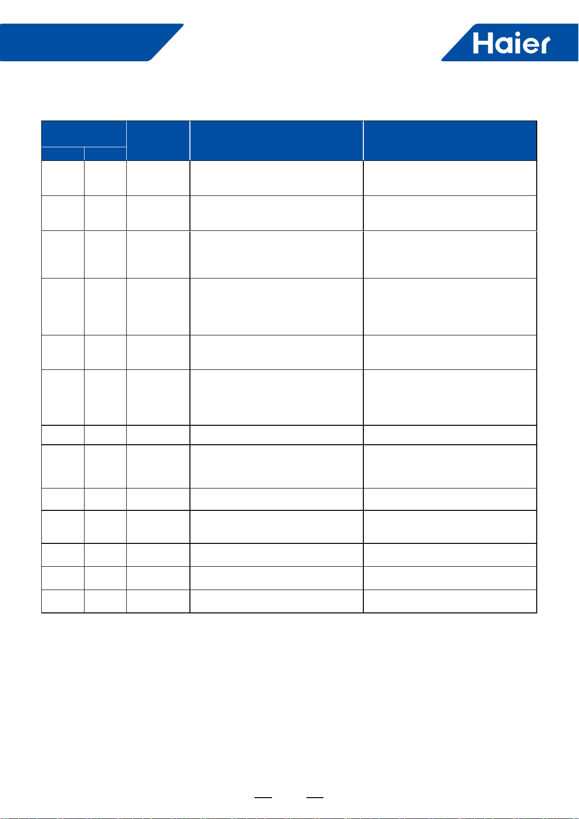
73
FlexFit Pro
AM24LP2VHA AM36LP2VHA AM48LP2VHA
LED ash times of
indoor PCB
Wired
controller
display
Description Possible reasons
LED4 LED3
0 1 01 Malfunction of indoor unit ambient
temperature sensor
Sensor disconnected, broken, shorted,
or at wrong position.
0 2 02 Malfunction of indoor unit piping
temperature sensor
Sensor disconnected, broken, shorted,
or at wrong position.
0 4 04 PCB EEPROM error
EEPROM chip disconnected, broken,
or programmed incorrectly.
PCB defective.
0 7 07 Abnormal communication between
indoor and outdoor units
Poor wiring connections, faulty
wiring, poor power supply, incorrect
addressing of indoor units, faulty PCB.
0 8 08 Abnormal communication between
wired controller and indoor unit
Wrong connection or wired controller
broken, or PCB hardware malfunction
0 12 0C Malfunction of drain system
Condensate pump disconnected
or faulty, oat switch a wrong
position, disconnected or faulty, or a
disconnection of the short circuit bridge
0 13 0D Zero cross sigal wrong Zero cross signal not detected
0 14 0E Abnormal communication between
main control PCB & fan motor drive
Fan motor disconnected, faulty wiring,
motor failure, or faulty circuit to motor
0 15 0F Fan motor overcurrent Fan motor current too high
0 17 11 DC voltage high or low DC voltage of the fan motor driver too
high or too low
0 18 12 F.M.D temperature high Fan motor driver over 95°C
0 19 13 Fan motor out of step Wrong rotor location detected
M (≥1) N (≥0) /Error of the outdoor unit See note 1,2
High Static Duct Models
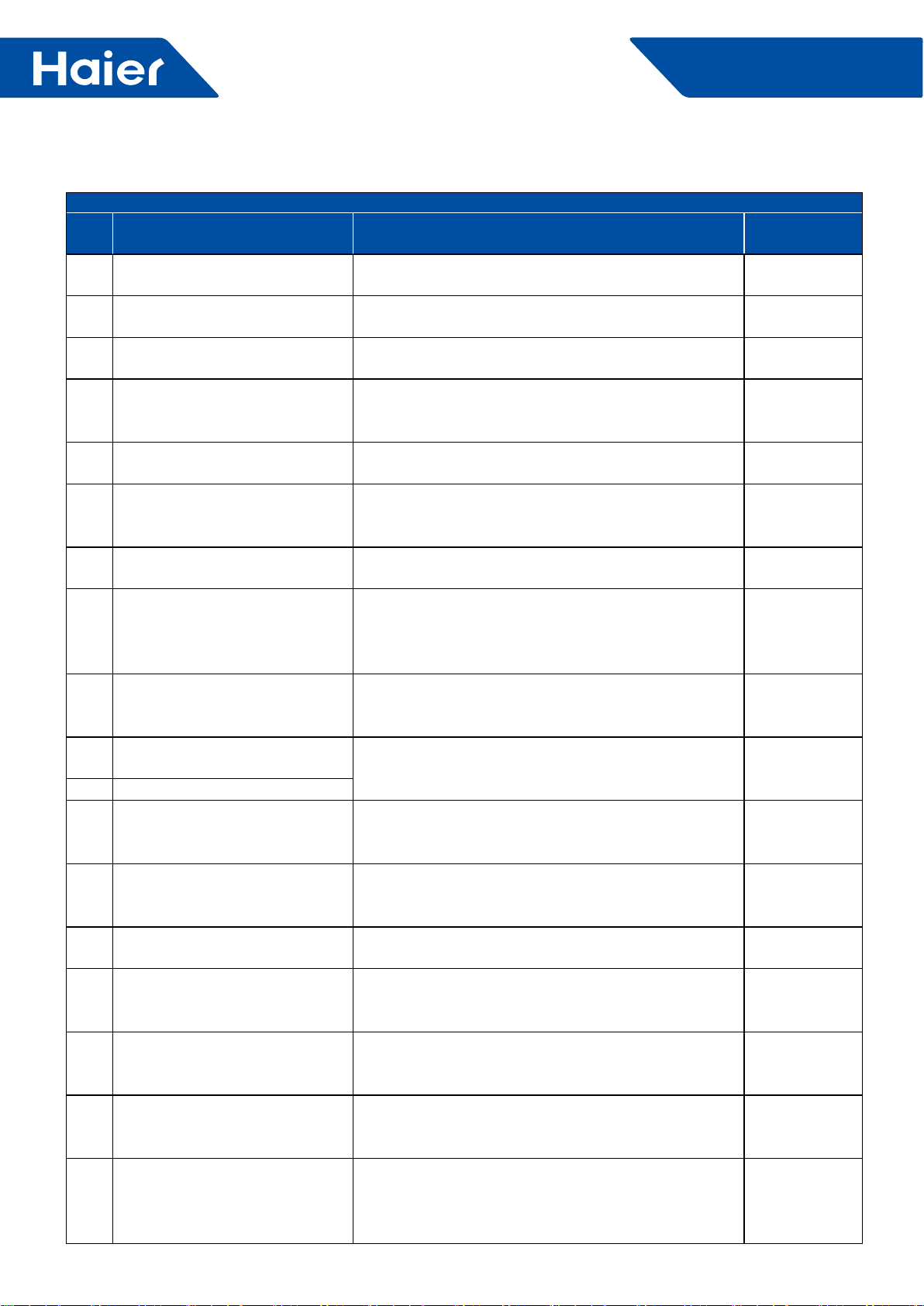
74
FlexFit Pro
4.2 1U24LP2VHA 1U36LP2VHA 1U48LP2VHA
Troubleshooting
Error
code Malfunction Description Diagnosis and Analysis. Remark
1EEPROM malfunction EEPROM chip damaged or data wrong or related
circuit damaged. Non-resumable
2PIM (power intelligent module)
hardware over current
Input over current occured been detected by PIM’s
hardware. Resumable
3Compressor over current during
deceleration
Over current occured during compressor deceleration
period. Non-resumable
4
Communication abnormal
between control board and
compressor driver module
Control board can not communicating with compressor
driver module over 4 minutes Resumable
5Compressor overcurrent detected
by control board
Compressor over current been detected by control
board Non-resumable
6DC voltage or AC voltage high
AC power supply of the driver module get voltage over
280VAC or driver module get high DC-BUS voltage
over 390VDC.
Resumable
7Compressor current sampling
circuit fault
The driver module’s Compressor current sampling
circuit damaged. Non-resumable
8Discharge temperature too high
protection
Compressor discharge temperature over 115°C, error
clear within 3 minutes if temperature goes down and
lower than 115°C. Error status lock if it occurs 3 times
in 1 hour.
Non-resumable
9DC fan motor fault
DC fan motor damage or not connected or related
circuit broken. Error status conrm and lock if occurs 3
times within 30 minutes.
Non-resumable
10 Outdoor defrosting temp. sensor
Te abnormal
Sensor temperature been detected below -55°C or
higher than 90°C or been detected as short circuit or
open circuit..
Resumable
11 Suction temp.sensor Ts abnormal
12 Outdoor ambient temp. sensor Ta
abnormal
Sensor temperature been detected below -40°C or
higher than 90°C or been detected short circuit or open
circuit.
Resumable
13 Discharging temp. sensor Td
abnormal
Sensor temperature been detected below -40°C or
higher than 150°C or been detected short circuit or
open circuit .
Resumable
14 PFC circuit loop high voltage Overvoltage been detected in driver module’s power
factor correction circuit loop. Resumable
15
Communication abnormal
between indoor unit and outdoor
unit
Outdoor unit control board can not communicating with
intdoor unit control board over 4 minutes. Resumable
16 Lack of refrigerant or discharging
pipe blocked
Discharge & suction temperatureTd-Ts≥80°C after
compressor started 10 minutes.Error status lock if it
occurs 3 times in 1 hour.
Non-resumable
17 4-way vavle converse abnormal
Indoor pipe & indoor ambient temperature
Tm-Tai≥5°C after compress- or started 10 minutes.
Error status lock if it occurs 3 times in 1 hour.
Non-resumable
18 Compressor motor
desynchronizing
Rotor desynchronizing occured, caused by overload or
load sharply uctuating or compressor current sensor
cicuit abnormal or one of the inverter’s gate drive signal
missing.
Non-resumable
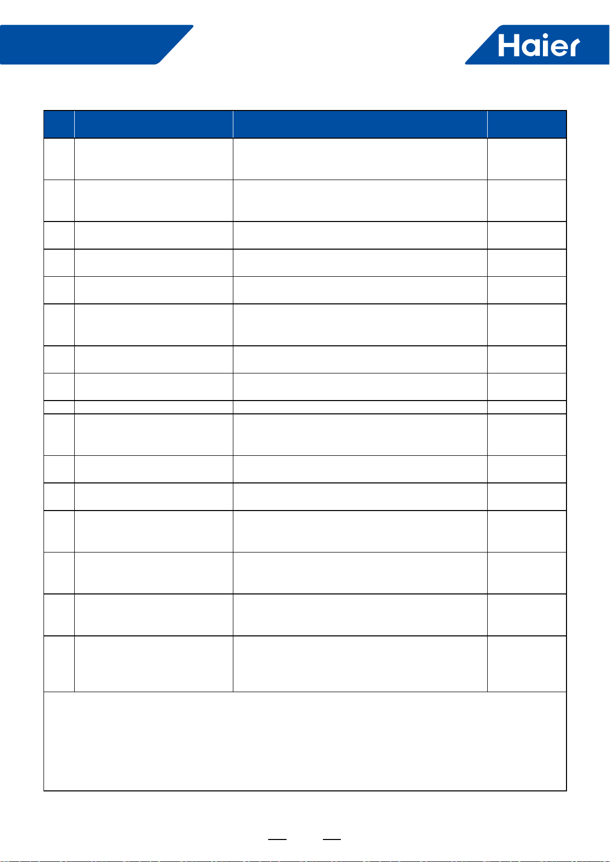
75
FlexFit Pro
Error
code Malfunction Description Diagnosis and Analysis Remark
19 DC voltage or AC voltage low
AC power supply of the driver module get voltage
lower than 155VAC or driver module get high DC-BUS
voltage lower than 180VDC.
Resumable
20 Indoor pipe temperature too high
protection
Indoor pipe temperature Tm over 63°C, error clear
within 3 minutes if temperature goes down and lower
than 52°C.
Resumable
22 PFC circuit loop overcurrent Overcurrent been detected in power factor correction
circuit loop. Resumable
23 Temperature too high for
compressor driver module
Compressor driver module’s PIM temperature over
90°C, Error stat-us lock if it occurs 3 times in 1 hour. Non-resumable
24 Compressor start failure Compressor start failure been detected by driver driver
module. Non-resumable
25 Input overcurrent of the drive
module
Input current of the compressor drive module higher
than 32A (double fan model) or 27A (single fan) , Lock
if it occurs 3 times in 1 hour.
Non-resumable
26 Lack phase of the drive module Lack phase of the drive module’s power supply.(three
phase type) Non-resumable
27 Input current sampling circuit
fault
The driver module’s input current sampling circuit
damaged. Resumable
28 No wiring of the compressor No wiring between compressor and it’s driver module. Non-resumable
37 Compressor overcurrent detected
by compressor driver module
Compressor phase U or V or W current over 27A
(single phase model) or 19.1A (single phase model)
occured during non-rated period.
Resumable
38 Drive module’s ambient temp.
sensor abnormal
The temperature detected is not within the range of
-25°C to 150 °C. Resumable
39 Mid-condenser temp. sensor TC
abnormal
The temperature detected is not within the range of
-55°C to 90 °C. Resumable
42 High pressure switch abnormal
After compressor running for 3 minutes, switch been
detected open circuit for 30seconds, Error lock if it
occurs 3 times in 1 hour.
Non-resumable
43 Low pressure switch abnormal
After compressor running for 3 minutes, switch been
detected uncon-nected for 60seconds or unconnected
for 30seconds at standby.
Non-resumable
44
Outdoor condenser
temperatureTC too high
protection
The maximum temperature value of Tc and Te is over
65 °C, Error lock if it occurs 3 times in 30 minutes. Non-resumable
45 System low pressure protection
The minimum temperature value of indoor pipe Tm
and outdoorTs is lower than-45 °C at cooling mode or
minimum temperature value of outdoor Tc and outdoor
Te is lower than-45 °C.
Non-resumable
Note:
1. The ou.tdoor control board’s LED3 indicates the outdoor error code. for example, the error code 12, LED3 will
display 12 and keep ashing.
2. Non-resumable means error will not clear unless: a. clean the fault factor b. Turn off the power supply and
turn on again after point a achieved.
3. The indoor unit can also indictes the outdoor malfuction code too. Please refer to indoor unit manul to get the
method.
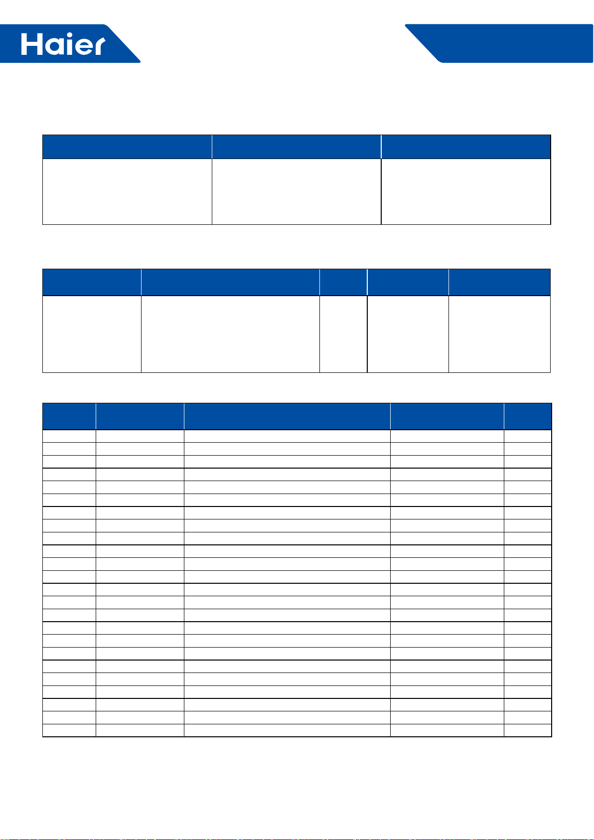
76
FlexFit Pro
4.3 Power Module Error Codes for 1U24LP2VHA 1U36LP2VHA
1. Drive Status Indication
LED LED display Description LED position
LED 601 (GREEN )
Flashing (on 1s, Off 1s) : Drive is
operating normally Flashing (on
0.25s off 0.25s, flashes n times and
then off 2s as a period) : Module
board failure
Module board
2. Protection function
Protection style:
Protection style Explanation LED LED display
Description ERROR Recovery
Shutdown protection
When voltage, temperature, or current
reach the limit of the protection level,
the unit will shut off, and the LED will
display the error code.
LED 601
(GREEN)
Flashes n times,
off 2s; (n is the
error code)
Needs to keep the
error information
2min, then ERROR
Recovery
3. Shutdown Protection Error Codes
Error code Hardware/software
protection Error Detail Protection Level Error
symbol
1Software PIM module overheat 105°C and continued 5s 01H
2Software PIM temperature sampling failure / 18H
3Software Overcurrent protection when limit frequency / 02H
4Hardware Hardware protection PIM_INT PIM_INT 04H
6Software DC under voltage 180V 05H
7Software DC high voltage 390V 06H
8Software Communication error / 07H
9Software Output lack of phase / 16H
10 Software Preset / /
11 Software U phase overcurrent 40A 0AH
12 Software Compressor is out of step / 0EH
13 Software V phase overcurrent 40A 0CH
14 software W phase overcurrent 40A 0DH
15 Software Compressor startup failure / 0FH
16 Software Phase current sampling failure / 09H
19 Software AC input under voltage 155V 11H
20 Software AC input overvoltage 280V 12H
21 Software AC input overcurrent 35A 13H
22 Software Input current sampling failure / 08H
23 Preset
24 Preset
25 Preset
27 Preset
30 Preset
Appendix A Protection function logic and protection level

77
FlexFit Pro
PIM temperature protection
Temperature more than 105°C, and continue 5 seconds, then drive shutdown protection.
Compressor startup failure protection
The drive will attempt to start the compressor 5 times, at intervals of 15 seconds. When the drive is making five
times the driving signal cannot normally drive the compressor, for the protection of the relevant parts, compressor
immediately shut down, and the drive will have the compressor drive failure protection.
Limit frequency/shutdown protection
Compressor current protection:
Error Protection Protection condition Result symbol
Shutdown
protection
Compressor phase current>compressor phase current shutdown
protection current (RMS) , the compressor immediately stop, drive into the
limited-frequency overcurrent protection.
Limit
frequency
protection
Compressor phase current> compressor Phase current Limit frequency
protection current (RMS) , the compressor will decrease the frequency by
the 2Hz/sec rate.
Limit frequency
protection
After compressor decrease the frequency, compressor phase current
limit frequency protection current (RMS) ≥compressor phase current>
compressor phase current protection recovery current (RMS) , forbid
increase the compressor frequency.
Forbid increase
the compressor
frequency
Protection
recovery
Compressor phase current≤Compressor phase current protection recovery
current (RMS) , cancel the compressor limit frequency protection and
normally operation
Drive input current protection:
Error Protection Protection Condition Result symbol
Shutdown
protection
Compressor phase current>compressor phase current shutdown
protection current (RMS) , the compressor immediately stop, drive into the
limitedfrequency overcurrent protection.
Limit
frequency
protection
Compressor phase current>compressor Phase current limit frequency
protection current (RMS) , the compressor will decrease the frequency by
the 2Hz/sec rate.
Limit frequency
protection
After compressor decrease the frequency, compressor phase current
limit frequency protection current (RMS) ≥compressor phase current>
compressor phase current protection recovery current (RMS) , forbid
increase the compressor frequency.
Forbid increase
the compressor
frequency
Protection
recovery
Compressor phase current≤Compressor phase current protection recovery
current (RMS) , cancel the compressor limit frequency protection and
normally operation.
78
FlexFit Pro
DC bus over/under voltage protection
Bus voltage>overvoltage shutdown value: the compressor stops, then switches into the bus overvoltage protection.
Bus voltage<overvoltage recovery value, cancel the bus overvoltage protection.
Bus voltage<under voltage shutdown value: the compressor stops, then switches into the bus under voltage
protection.
Bus voltage<voltage recovery value, cancel the bus under voltage protection.
AC input over/under voltage protection
Drive comes with AC voltage detection, when input voltage is too low, the input current will be too high, damage can
occur
Input voltage<under voltage shutdown value, the compressor stops, then switches into the input under voltage
protection.
Input voltage>voltage recovery value, cancel the under voltage protection.
Drive comes with AC voltage detection, if the input voltage is too high, damage can occur.
Input voltage>over-voltage shutdown value, the compressor stops, then switches into the input overvoltage
protection.
Input voltage<over-voltage recovery value, cancel input over-voltage protection.
Communication error:
Drive priority detects the model code after power is on for 30 seconds .
Compressor type Model Code
TNB220FFEMC 0x02DC
TNB306FFEMC 0x02DD
If the model code is not within the model range or or the correct data is not received within the 30 seconds, the unit
will go into a communications failure mode and will shut down.
When the correct data is within the model code range the error will be canceled.
Note: For debug mode, when the model code is not within the range of models, sentenced to communication
failure; when the model code within the model range, then cancel the error
PFC switch value:
When PFC sampling current>PFC open switch current and the DC bus average voltage<PFC open switch voltage,
then opening PFC;
When PFC sampling current<PFC off switch current, off PFC.
Protection value
Compressor type TNB220FFEMC:
No. Error Description
Device
Protection
Value
1Compressor phase current Limit frequency protection shutdown current value (RMS) 18A
2Compressor phase current Limit frequency protection decrease frequency current value (RMS) 13A
3Compressor phase current Limit frequency protection recovery current value (RMS) 10A
4PIMTemperature shutdown protection 105°C
5Drive input current limit frequency protection shutdown current value (RMS) 23A
6Drive input current limit frequency protection decrease frequency current value (RMS) 18A
7Drive input current limit frequency protection recovery current value (RMS) 13A
8AC input overvoltage shutdown value 280V
9AC input overvoltage recovery value 265V
10 AC input under voltage shutdown value 155V
11 AC input under voltage recovery value 185V
12 DC bus overvoltage shutdown value 390V
13 DC bus overvoltage recovery value 380V
79
FlexFit Pro
No. Error Description
Device
Protection
Value
14 DC bus under voltage shutdown value 180V
15 DC bus under voltage recovery value 200V
16 Communication shutdown protection time 30S
17 PFC open switch current (RMS) 8A
18 PFC open switch voltage 360V
19 PFC off switch current (RMS) 5A
Compressor type TNB306FFEMC:
No. Error Description
Device
Protection
Value
1Compressor phase current Limit frequency protection shutdown current value (RMS) 23A
2Compressor phase current Limit frequency protection decrease frequency current value
(RMS) 18A
3Compressor phase current Limit frequency protection recovery current value (RMS) 14A
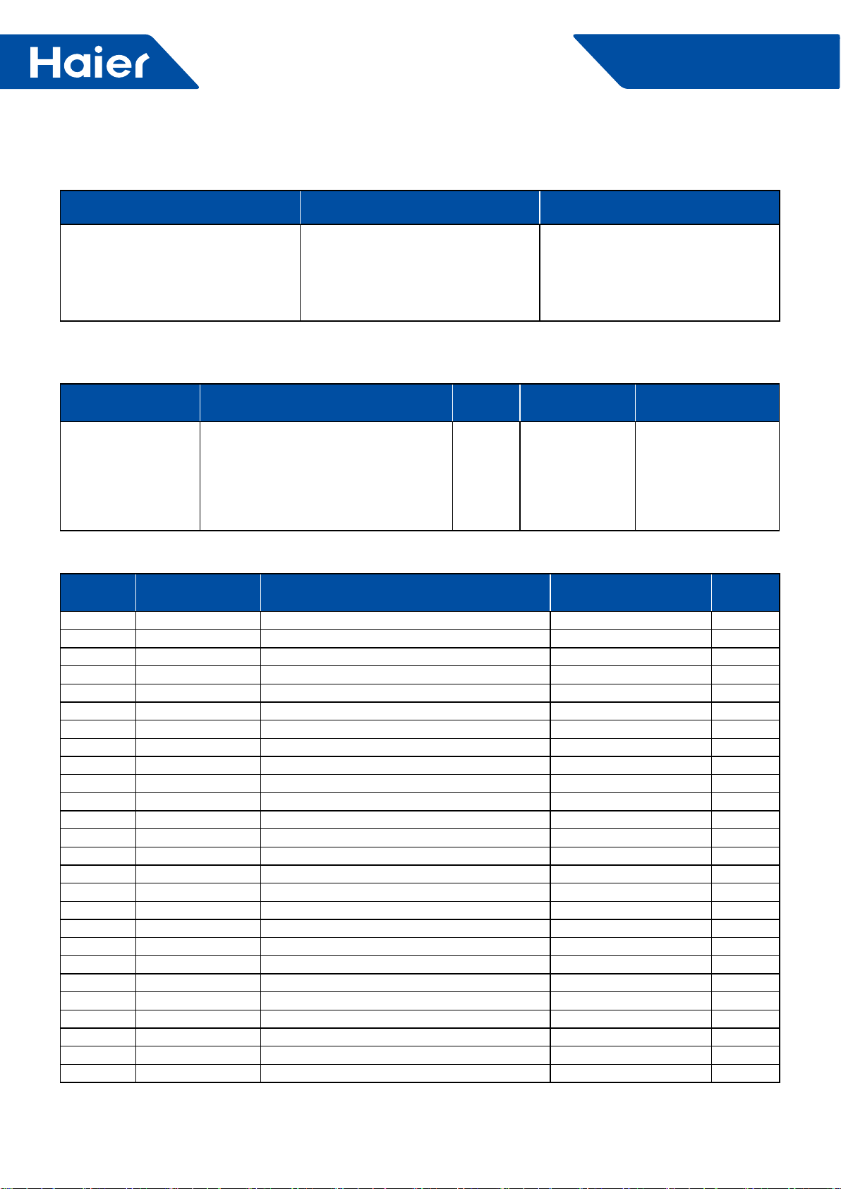
80
FlexFit Pro
4.4 Power module error code checking for 1U48LP2VHA
1. Explanation of LED
LED Model Explanation of LED Display LED Location
LED 601 (Green)
Flashing (on,1s, off,1s) : driver
works normally. Flashing (on,0.25s,
off, 0.25s, flash several times, then
off for 2 seconds ) : power module
failure.
Power module
2. Protection function
Category of protection:
Category Explanation LED LED Display
Description Error Recovery
Shutdown protection
When the voltage, current, temperature,
etc. to meet the shutdown protection
Level, drive immediately stop output,
and LED display fault information, and
upload the error symbol
LED 601
(GREEN)
Flashes n times,
off 2s; (n is the
error code)
Needs to keep the
error information 2min,
then error Recovery
3. Protection error lists
Error Code Hardware/software
Protection Error Detail Protection Level Display
Symbol
1Software PIM module overheat 105°C and continued 5s 01H
2Software PIM temperature sampling failure / 18H
3Software Overcurrent protection when limit frequency / 02H
4Hardware Hardware protection PIM_INT PIM_INT 04H
6Software DC under voltage 180V 05H
7Software DC high voltage 390V 06H
8Software Communication error / 07H
9Software Output lack of Phase / 16H
10 Software Reserved / /
11 Software U phase overcurrent 40A 0AH
12 Software Compressor is out of step / 0EH
13 Software V phase overcurrent 40A 0CH
14 software W phase overcurrent 40A 0DH
15 Software Compressor startup failure / 0FH
16 Software Phase current sampling failure / 09H
19 Software AC input under voltage 155V 11H
20 Software AC input overvoltage 280V 12H
21 Software AC input overcurrent 35A 13H
22 Software Input current sampling failure / 08H
23 Preset
24 Preset
25 Preset
27 Preset
30 Preset
32 Software PFC overcurrent of 75A 14H
34 Software PFC high voltage 430V 15H
Appendix A Protection function logic and protection level
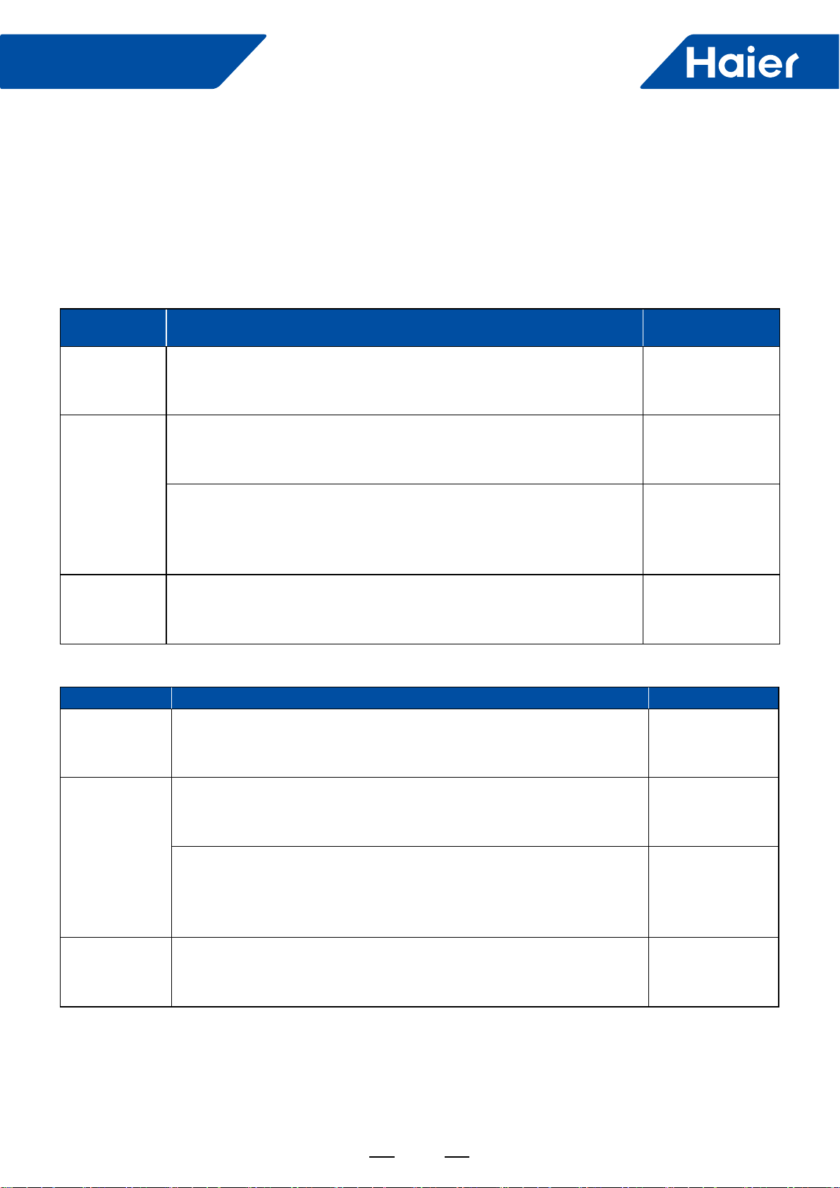
81
FlexFit Pro
PIM temperature protection:
Temperature more than 105°C, and continue 5 seconds, then drive shutdown protection.
Compressor startup failure protection:
The drive will attempt to start the compressor 5 times, at intervals of 15 seconds. When the drive is making five
times the driving signal cannot normally drive the compressor, for the protection of the relevant parts, compressor
will immediately shut down, and the drive will have the compressor drive failure protection.
Limit frequency/shutdown protection
Compressor current protection:
Error
Protection Protection Condition Result Symbol
Shutdown
protection
Compressor phase current> compressor phase current shutdown
protection current (RMS) , the compressor immediately stop, drive into the
limitedfrequency overcurrent protection.
Limit
frequency
protection
Compressor phase current>compressor Phase current Limit frequency
protection current (RMS) , the compressor will decrease the frequency by
the 2Hz/sec rate.
Limit frequency
protection
After compressor decrease the frequency, compressor phase current
limit frequency protection current (RMS) ≥compressor phase current>
compressor phase current protection recovery current (RMS) , forbid
increase the compressor frequency.
Forbid increase
the compressor
frequency
Protection
recovery
Compressor phase current≤Compressor phase current protection recovery
current (RMS) , cancel the compressor limit frequency protection and
normally operation.
Input current protection of driver:
Error Protection Protection Condition Result Symbol
Shutdown
protection
Compressor phase current>compressor phase current shutdown
protection current (RMS) , the compressor immediately stop, drive into the
limitedfrequency overcurrent protection.
Limit frequency
protection
Compressor phase current>compressor Phase current limit frequency
protection current (RMS) , the compressor will decrease the frequency by
the 2Hz/sec rate.
Limit frequency
protection
After compressor decrease the frequency, compressor phase current
limit frequency protection current (RMS) ≥compressor phase current>
compressor phase current protection recovery current (RMS) , forbid
increase the compressor frequency.
forbid increase
the compressor
frequency
Protection
recovery
Compressor phase current≤Compressor phase current protection recovery
current (RMS) , cancel the compressor limit frequency protection and
normally operation

82
FlexFit Pro
DC bus over/under voltage protection:
Bus voltage>overvoltage shutdown value, the compressor stop, then drive into the bus overvoltage protection.
Bus voltage<overvoltage recovery value, cancel the bus overvoltage protection.
Bus voltage<under voltage shutdown value, the compressor stop, then drive into the bus under voltage protection.
Bus voltage>voltage recovery value, cancel the bus under voltage protection.
AC input over/under voltage protection:
Drive come with AC voltage detection, avoid the input voltage is too low, cause the input current is too high,
damage the device.
Input voltage<under voltage shutdown value, the compressor stop, then drive into the input under voltage
protection.
Input voltage>voltage recovery value, cancel the under voltage protection.
Drive come with AC voltage detection, avoid the input voltage is too high, damage the device.
Input voltage>overvoltage shutdown value, the compressor stop, then drive into the input overvoltage protection.
Input voltage<overvoltage recovery value, cancel input overvoltage protection.
Communication error:
Drive priority detect the model code after power on .the 30s after power on is the time for the model code setting.
And need to complete the model code setting within this 30s, if setting completely, are not allowed to change.
Compressor type Model code
MNB42FDAMC 0x03DE
If model code is our of model range or no right communication data is received within 30s, communication failure is
conrmed, execute stop protection under communication failure, in the meanwhile, relevant error code is sent back.
When communication is conrmed, if right data is received again and within normal range, error is removed.
Remarks: for debugging mode, when model code is not within model range, communication error is conrmed,
when model code is within model range, error is removed.
PFC switch value
When PFC sampling current>PFC open switch current and the DC bus average voltage<PFC open switch voltage,
then opening PFC;
When PFC sampling current<PFC off switch current, off PFC.
Protection value
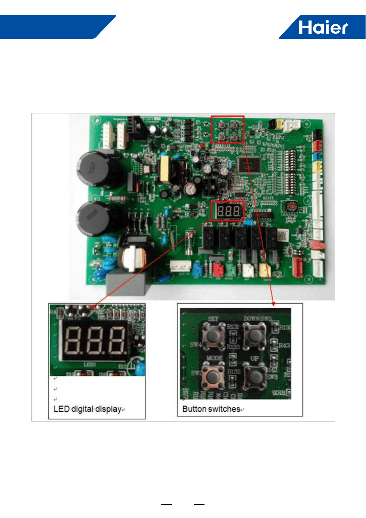
83
FlexFit Pro
5. Instructions of parameters & Checking Error Codes
5.1 From where to do the parameters checking work?
5.2 Where are the digital LED display and the button switches?
Location of LED and button switches which on the outdoor main control PCB
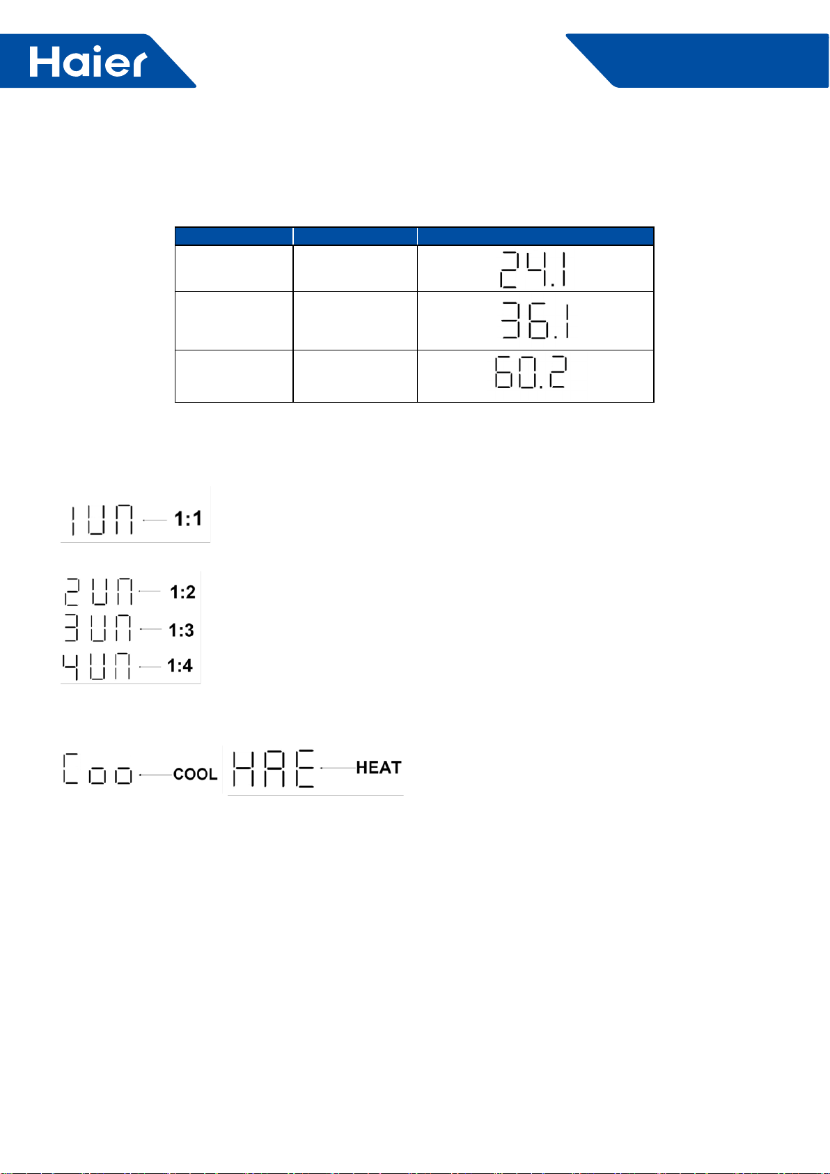
84
FlexFit Pro
5.3 What does the Default Display at non-checking mode?
a. When outdoor unit gets power, the LED digital display will show the model code rst, as following list.
MODEL MODEL CODE DISPLAY
1U24LP2VHA 24.1
1U36LP2VHA 36.1
1U48LP2VHA 60.2
b. Then after step a, if the communication between indoor and outdoor unit is correct, the LED digital display
will show the quantity of indoor units.
For single splits system, it will show 1UN.
ForFor a multi system (future) it will show 2UN or 3UN or 4UN
c. Then after step b and if has reached the outdoor unit’s start time, the LED digital display will indicate the indoor
unit’s setting mode, cool or heat. This will be displayed for 5 seconds.
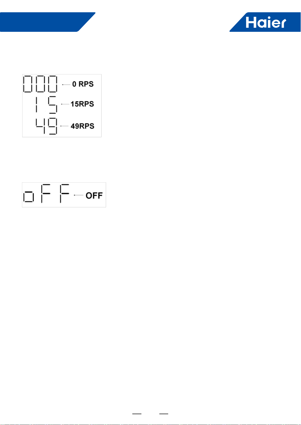
85
FlexFit Pro
5.4 Checking the Parameters
d. Then after step c and it will show the speed of the compressor rotor, 000 stands for speed is 0 RPS, 15 stands
for 15 RPS, 49 stands for 49 RPS, and so on.
e. After Step D, when the indoor temperature reaches the set point, the outdoor unit will shut off and the LED
display will be 000. 30 seconds later the LED will shut off. If the unit is shut off manually via the controller, the
LED will display OFF for 30 seconds then will go out.
Step1: Press and hold the MODE button for 5 seconds and release, then The LED display will show the current
mode and will be ashing.
Step2: Press and hold the SET button for 3 seconds then release, The LED display will keep MODE lighted without
ashing..
Step3: Press and hold the SET button for 3 seconds again then release, The LED will display FRQ and will ash
the present speed of the compressor.
Step4: Scroll pages to view the other parameters by using UP or DOWN button
Fig. 4.1 or Fig. 4.2 shows steps above.
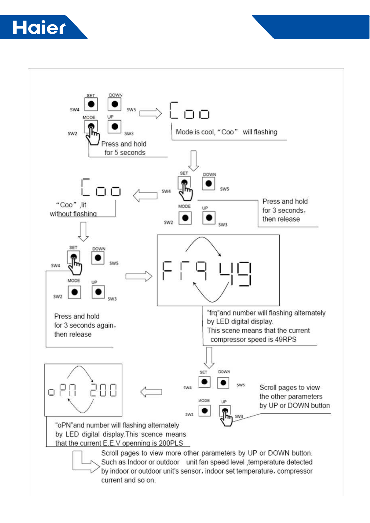
86
FlexFit Pro
Fig.4.1
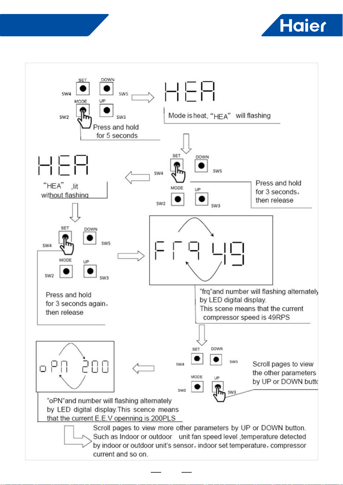
87
FlexFit Pro
Fig.4.2
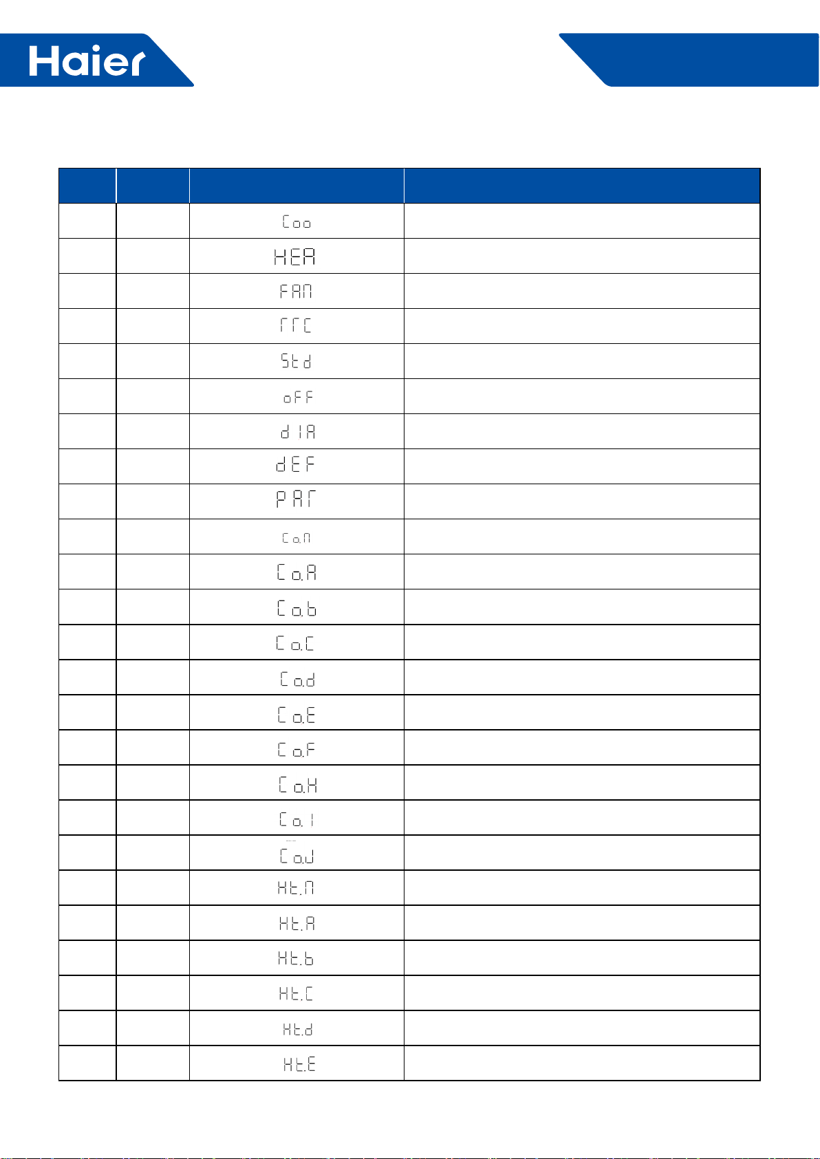
88
FlexFit Pro
5.5 Outdoor Unit LED Display
No. Symbol LED Digital Display Explanation
1Coo Cool mode
2 HEA Heat mode
3 Fan Fan mode
4 rrC Refrigerant Recovery
5Stb Manually forced stand by
6 OFF Compressor at OFF status
7dIA Diagnose
8dEF Manually forced defrost
9 pAr Parameters checking
10 Co.N Cool mode of EER test condition
11 Co.A Cool mode of SEER test condition A
12 Co.b Cool mode of SEER test condition B
13 Co.C Cool mode of SEER test condition C
14 Co.d Cool mode of SEER test condition D
15 Co.E Cool mode of SEER test condition E
16 Co.F Cool mode of SEER test condition F
17 Co.H Cool mode of SEER test condition F
18 CO.I Cool mode of SEER test condition I
19 CO.J Cool mode of SEER test condition J
20 Ht.N Heat mode of EER test condition
21 Ht.A Heat mode of SCOP test condition A
22 Ht.b Heat mode of SCOP test condition B
23 Ht.C Heat mode of SCOP test condition C
24 Ht.d Heat mode of SCOP test condition D
22 Ht.E Heat mode of SCOP test condition E

89
FlexFit Pro
No. Symbol LED Digital Display Explanation
23 Ht.F Heat mode of SCOP test condition F
24 Ht.H Heat mode of SCOP test condition H
25 Ht.I Heat mode of SCOP test condition I
26 Ht.J Heat mode of SCOP test condition J
27 qut Quit
28 Frq Frequency (speed of compressor, equals revolutions per
second (RPS) ) .
29 opN Electronic expansion valve opening
29 I.FN Indoor unit fan speed level
30 o. FN Indoor unit fan speed level
31 tAo Temperature of outdoor ambient
32 tc Temperature of outdoor condenser
33 td Temperature of outdoor discharge
34 tE Temperature of outdoor defrost
35 tS Temperature of outdoor suction
36 tdr Temperature of compressor driver module
37 Idr Current of the compressor
38 tH Temperature of heat water (reserved)
39 tAI Temperature of indoor ambient
40 TCI Temperature of indoor condenser
41 tSt Setting temperature on indoor unit
42 UN UN=UNIT, 1UN means with 1 indoor unit:
2UN means with 2 indoor unit, MAXI application
43 r32 Refrigerant R32
44 OiL Unit gets compressor oil recycling mode
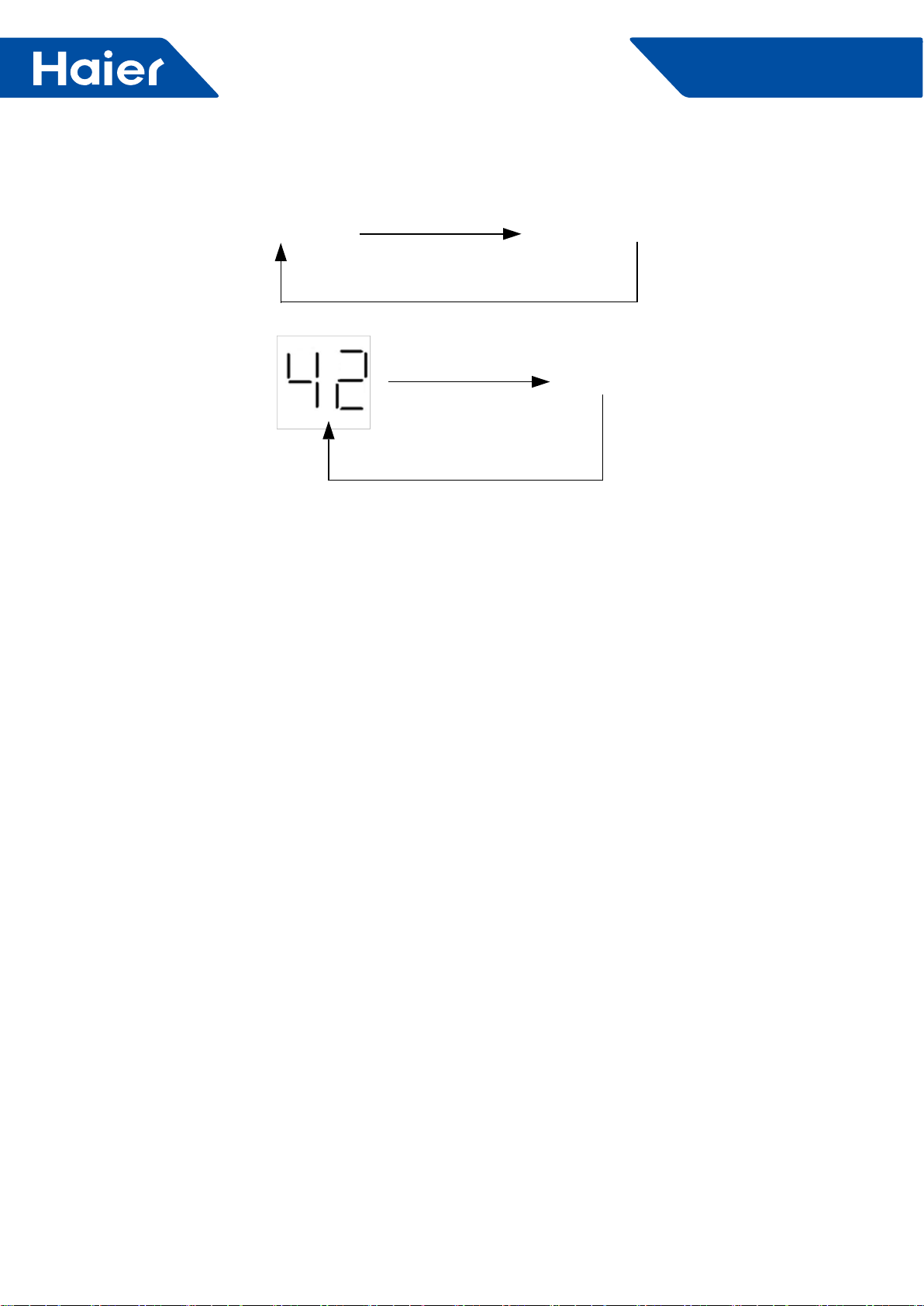
90
FlexFit Pro
5.6 Checking current outdoor unit error code
5.7 View previous error record (diagnosis mode)
If there is malfunction on the outdoor unit, the LED digital display will ashing like this repeating pattern:
Error code number ashing LED digital display extinguished
Example:
Extinguished
For an explanation of error codes, refer to the outdoor unit troubleshooting guide.
Step1: Press and hold the MODE button for 5 seconds and release, then the LED digital display will show the
current mode and will keep ashing.
Step2: Scroll up or down to view other modes.
Step3: Find mode "dig", press and hold the SET button for 3 seconds, then release.
Step3: When DIG is displayed, press and hold the SET button for 3 seconds then release. The LED will display the
last recorded error code.
Step4: Scroll pages to view the other last 10 times error code by using the UP or DOWN button. If only N (N≤10)
error has been recorded,, you can just nd last N times error record.
Fig.7.1 shows steps above.
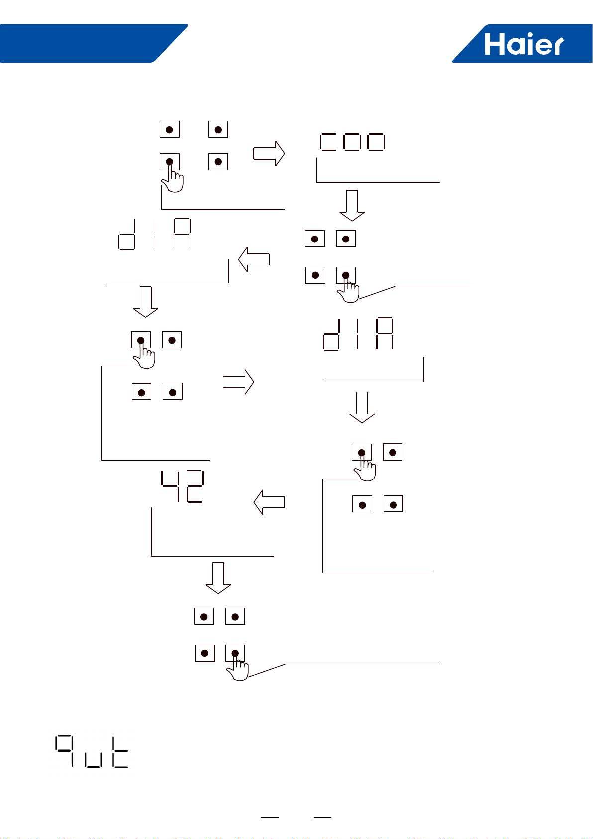
91
FlexFit Pro
Fig.7.1
Step1: Press and hold the MODE button for 15 seconds then release, then the LED digital display will show "QUT".
Step2: Press the SET button to quit the parameters checking mode or diagnosis mode.
5.8 How to quit the parameters checking mode or diagnosis mode
press and hold
for 5 seconds
SET
SW4
SW2
SW4
SW2
SW4
SW2
MODE
DOWN
SET DOWN
SET DOWN
SET DOWN
UP
MODE UP
MODE UP
SW5
SW3
SW5
SW3
SW4
SW2
MODE UP
SW5
SW3
SET DOWN
SW4
SW2
MODE UP
SW5
SW3
SW5
SW3
Mode is cool, “Coo”will flashing
“diA”
flashing
Scroll pages to view
the other modes
by UP or DOWN button
Press and hold
for 3 seconds
then release
“diA”
lit,without flashing
Scroll pages to view
the other last N times (N≤10) error code
by UP or DOWN button number will flashing
by LED digital display
This scene means that
last error code is 42 press and hold
for 3 seconds again.
then release

92
FlexFit Pro
6. Functions
6.1 Indoor unit:
6.1.1 Dehumidication operation (no humidity sensor )
1. The indoor unit will stop and send a signal to shut off the outdoor unit when Tai<60*F
NOTE: I do not have a degree symbol, so I used the "*". Please insert the degree symbol.
2. While in cooling mode, the indoor unit will send a call for cooling to the outdoor unit when Tai>Tset+2 degrees F.
3. When Tset<Tai≤Tset+2 degrees F,,the indoor unit will send a dehumidication signal to the outdoor unit to start
the compressor. The unit will run for 10 minutes in low fan speed then shut off for 6 minutes. When it stops it will
send stopping signal to outdoor. When indoor unit failure, it will run 10 minutes in low speed and stop 6 minutes.
Timing cycle keep the same. Slave units determine the fan speed through the state what outdoor sent.
4. When the room temperature is less than or equal to the set temperature, the indoor fan will operate on low speed
and shut off the compressor.
6.1.2 Auto running:
1. When entering AUTO for the rst time, the operating mode will be decided by the outdoor unit mode, the room
temperature, and the set temperature. For example; if Tai is equal to or greater than Tset, the unit will enter the
cooling mode. If Tai is<Tset the unit will enter the heating mode.
2. If the system is in the cooling mode and it has been off for 15 minutes, and Tai+1+Tdif<Tset, the unit will start the
heating mode.
3. If the system is in the heating mode and it has been off for 15 minutes, and Tai is greater than or equal to
Tset+1+corrected+Tdif, the unit will start the cooling mode.
4. The unit will enter the SLEEP function (if set) in both heating and cooling modes, yet will not change modes after
15 minutes of run time as outlined above.
5. Changing from heating to cooling whille in the AUTO mode can only occur within 15 minutes after the compressor
stops.
6.1.3 Indoor fan control:
1. Auto fan speed control
Cooling mode ΔT=Tai-Tset ; heating mode ΔT=Tset-Tai
*First time to enter auto fan mode, if ΔT>2, choose high speed; ΔT≤0, choose low speed, another choose middle
speed. If temperature sensor is off ,choose low speed. (1 degree transformation temperature difference)
When the speed mode is auto high speed, if ΔT<2, the speed mode will change to auto middle speed.
When the speed mode is auto middle speed, if ΔT<0, the speed mode will change to auto low speed; if ΔT>3, the
speed mode will change to auto high speed.
When the speed mode is auto low speed mode, if ΔT>1, the speed mode will change to auto middle speed.
The speed transformation under auto speed mode: It will delay 3 minutes from high speed to low speed and no
delay from low to high.
Salve units determine the fan speed according to the state what outdoor has sent in the auto speed mode.
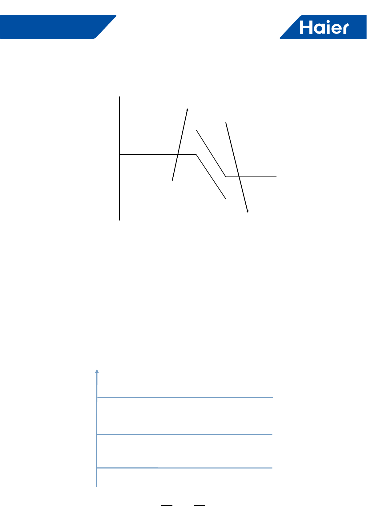
93
FlexFit Pro
2. Cold air prevention control
In heating mode, the indoor fan running state is decided by indoor coil temperature (Tm) after compressor starts.
Tm
30 (34) Setting airflow
Low speed
Stop
26 (30)
24 (26)
22 (23)
Note:
The numbers in the brackets is the temperature control point when the outdoor temperature is more than 10
degrees.
3. After-heat control:
When the compressor is off or the unit is off in the heating mode, the indoor fan will run for a maximum of 50
seconds in the low speed until the conditions in the above table are satisfied.
4. Cold air prevention during defrost:
When a call for defrost is received, the indoor fan will run in the after-heat mode for 20 seconds in low speed
before stopping. After the defrost cycle is complete, the fan will begin the cold air prevention cycle.
6.1.4 Anti-freeze:
The outdoor unit LED will display the anti-freeze protection mode. The indoor unit will not, as this function is not a
fault. The unit will end this mode automatically.
Anti-freeze protection of indoor unit in cooling mode
General control.
Frequency rises slowly as 1HZ/10s.
Remain unchanged.
Frequency decrease slowly as 1HZ/10s.
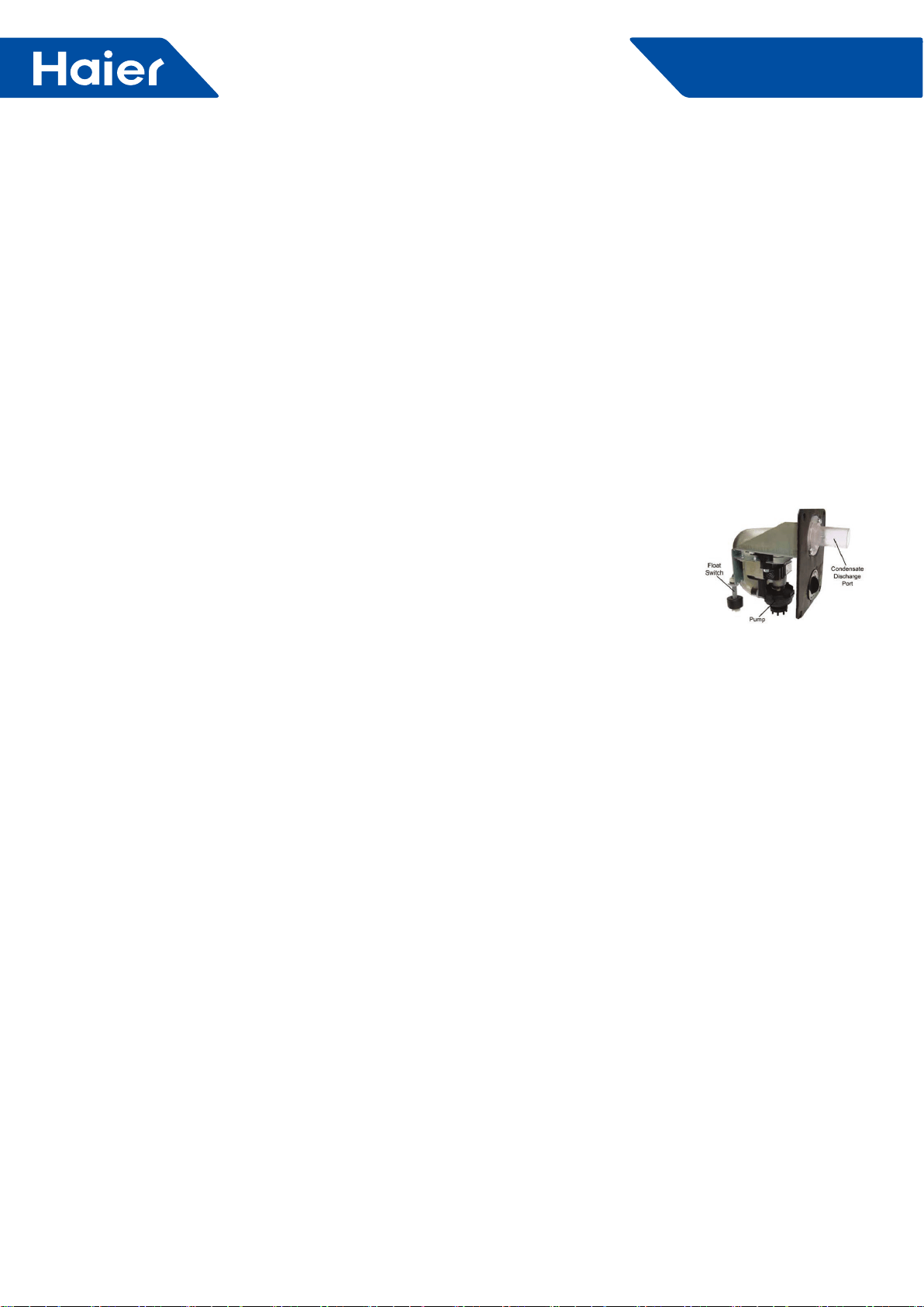
94
FlexFit Pro
When TM<6°C, the compressor frequency will decrease at the speed of 1HZ/10s;
When TM start to rise again, and 6°C<=TM<=8°C, the compressor frequency will remain unchanged.
When 8°C<TM<=10°C, the compressor frequency will rise at the speed of 1HZ/10s.
When the state of TM<2°C lasts for 10s after 6 minutes of the startup of the compressor, or the state of T<-20°C (E)
lasts for more than 2 hours in cooling mode, the compressor will stop. The unit will shut down for 5 minutes and the
temperature of the coil rise to 10°C (E) , it will be back up and running.
6.1.5 Control of oat switch and condensate pump:
6.1.6 Emergency switch
1. Emergency switch operation
If the emergency switch is pressed when shutting down the system, the set temperature is locked at 75 degrees F.
Pressing the switch again during start-up will return the system to normal.
2. Test run
To enter the test mode, press the emergency button for 5 seconds until two beeps are heard then release. The unit
will maintain the last mode it was in before the shutdown. If in cooling, the temperature will be locked at 61 degrees
F with high speed fan. Heating will be locked at 86 degrees F with high speed fan. To disable the test mode, press
the emergency button again or use the wired or remote controller.
6.1.7 Room card control (default is valid)
Room card invalid: if room card is invalid, using room card to turn ON/OFF (ON when close and OFF when open) is
valid, similar function to other controller.
Room card valid: if room card is valid, indoor will operate only when room card closes and then receives ON order
from other controllers.
6.1.8 Auto restart function:
1. When using wired controller: auto restart function is default valid (no need to set)
2. With the remote controller, press the SLEEP button 10 times within 5 seconds. The controller will beep 4 times
then enter the auto restart function. To exit, press the SLEEP button 10 times within 5 seconds. The controller
will beep 2 times then exit auto restart.
Auto restart default memory: ON/OFF/MODE/FAN/SET TEMP/HEALTH/SWING. If the timer or sleep functions are
set, they will be canceled when power is reapplied.
6.1.9 Forced defrost:
1. When using remote controller: when outdoor in heating or off state, set high fan, 86 degrees F, press sleep key 6
times in 5 seconds, and indoor beeps 3 times to enter manual defrosting.
2. When using wired controller : it will receive corresponding forced defrost signal and enter defrost.
1.. If in COOL or DRY mode: Compressor running (Thermal ON), then condensate pump is energiz
•When compressor stops (Thermal OFF), condensate pump runs for an additional 5 minutes
2.. If in COOL or DRY modes and compressor is running (Thermal ON) and the float switch opens for 5 minut
•Compressor will stop, the pump will continue to run
•If the float switch does not close, error code will display and pump continues to run
•If the float switch does close, the pump will continue to run for 5 additional minutes
3.. During standby (Thermal OFF) in COOL/DRY modes or in HEAT and FAN modes and float switch opens for 2 second
the condensate pump is energized.
•If the float switch closes, the pump will run an additional 5 minutes
•If the float does not close, the pump continues to run and error code is displayed
Note: When installing, the condensate discharge port at the top of the water pump must be
connected with drian pipe.
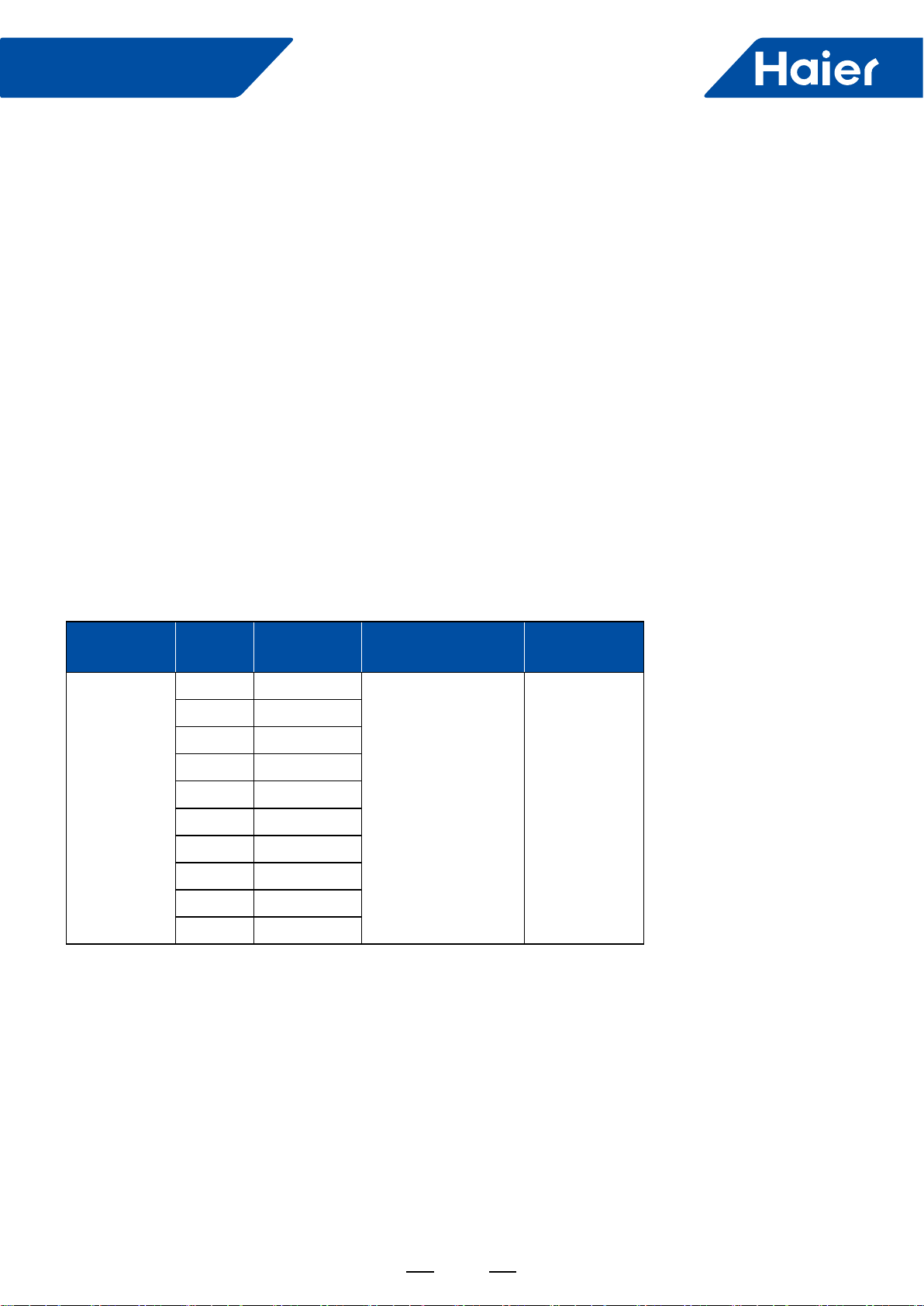
95
FlexFit Pro
6.1.10 Timing operation:
1) When using wired controller, unit will be controlled ON/OFF by wired controller
2) When using remote controller, unit will be ON/OFF according to set time by remote controller and current time.
6.1.11 Sleeping function:
1) When using wired controller, unit will be controlled ON/OFF by wired controller
2) When using remote controller, press sleep key to set sleep function including sleeping in heating and sleeping in
cooling. After setting sleeping function and then shift mode, sleeping will recount.
6.1.12 Swing control:
1) When choosing 24k Cassette:.
When powering on and initializing, it will Fully open for positioning, and then enter basic opening, fan motor
operating after blade moving to right position.
2) When choosing 36k/48k cassette, swinging will be controlled by invisible LED.
It will swing according to default position when first powering on, and will swing according to swing position
before turning off.
6.1.13 External static pressure setting method
There are 2 ways to achieve the external static pressure setting:
A. by Infrared remote controller
B. by wired controller.
MOEDL
Static
Pressure
Level ( N)
Externalstatic
Pressure
Select by Infrared
Remote Controller
Select
By Wired
Controller
AM36LP2VHA
AM48LP2VHA
1 25Pa
YR-HBS01 +RE-
02→FAN mode ,fan
speed high→press
HEALTH button 4+N
times(1≤N≤10,integer)
within 12 seconds
Select static
pressure
Level N by the
display interface
2 37Pa
3 50Pa
4 70Pa
5 90Pa
6 100Pa
7 110Pa
8 120Pa
9 130Pa
10 150Pa
A.Static selection via remote:
1. Prepare: Infrared remote controller YR-HBS01 , infrared remote receiver RE-02(plug RE-02 connector to indoor
PCB CN29)
2. Method:
Step 1: set the remote controller in the high speed FAN mode.
Step 2: then aim the remote controller at the infrared remote receiver RE-02, press HEALTH button 4+N
times(1≤N≤10,integer) within 12 seconds ,The receiver will beep N+1 times indicating the static pressure level has
been set.
Note: For Infrared remote controller YR-HBS01, press ON/OFF button to set the controller at the OFF position.
Open the cover of the controller and press the FRESH button to enter the FAN mode interface.
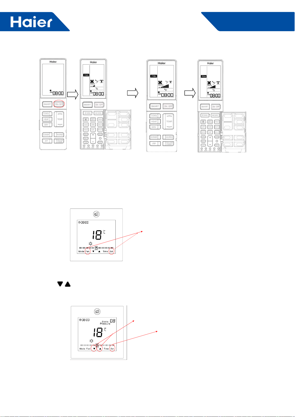
96
FlexFit Pro
B.Static selection via wired controller:
1. Prepare: wired controller YR-E17, plug wired controller connector to indoor PCB CN3
2. Method:
2.1 In the state of ON and non screen saving state, press Fan + Set keys for 5s to enter static pressure grade
adjustment.
Press together and hold for 5
seconds
2.2 Static pressure icon will ash and the current setting will be displayed
2.3. Press key to change static pressure grade N(1≤N≤10,integer), then press Set key to conrm.
Use these buttons to adjust static pressure
level numbers.
press Set key to conrm.
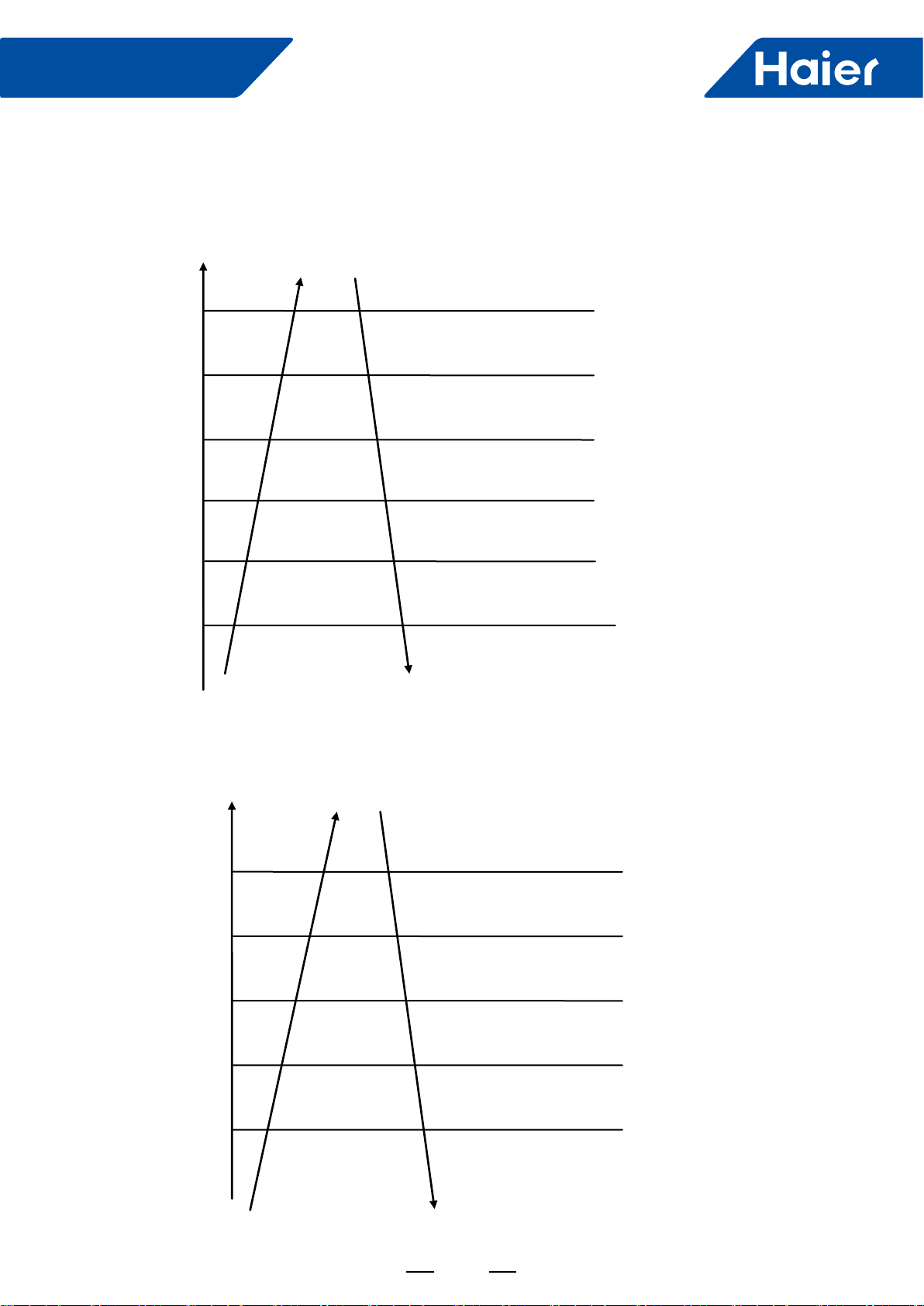
97
FlexFit Pro
6.2 Outdoor unit
6.2.1 Compressor discharge temp. (TD) high temp. protection function.
Discharge temperature
Td
115°C
112°C
108°C
105°C
95°C
93°C
If it lasts 3 seconds, the unit will stop. After standing
by 3 minutes, the unit can restart. If it happens 3
times in 60 minutes. The unit stops and alarms. it
will disappear if unit is powered on.
Fast frequency reduction 2HZ/S
Fast frequency reduction 1HZ/S
Fast frequency reduction 1HZ/10S
Keep frequency
Slow frequency up 1HZ/10S
Common control
6.2.2 Condenser overheat protection
When cooling, compare TC with TE. Choose the bigger one, TC’. TC’=MAX.[TC, TE]. You can control the high
pressure through controlling TC’.
Slow frequency up 1HZ/10S
Common control
65°C
TC’_cooling
64°C
61°C
59°C
55°C
If it lasts 5 seconds, the unit will stop and alarm.
After standing by 3 minutes, unit can restart. If it
happens 3 times in 30 minutes, unit also stops and
alarms. It will disappear if unit is powered on..
Fast frequency reduction 2HZ/S
Slow frequency reduction 1HZ/10S
Keep frequency
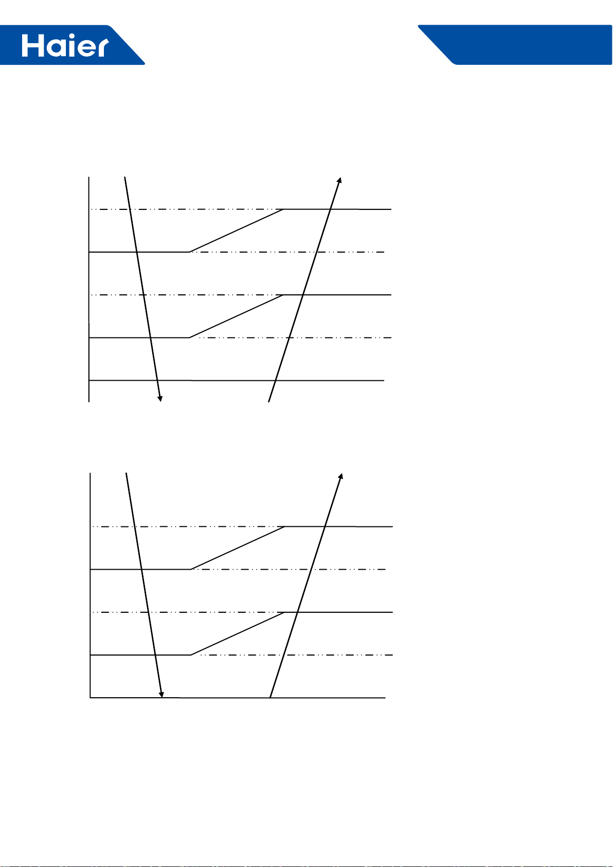
98
FlexFit Pro
6.2.3 Low pressure protection
The low pressure is controlled by simulating evaporating temperature:
When cooling, compare the evaporating temp. with the compressor suction temp. and choose the lower one (Teva c)
to compare.
-25°C
Teva_c
-30°C
-35°C
-40°C
-45°C
If it lasts 5 seconds, unit will stop and Alarm.
After standing by 3 minutes, unit will restart. If
it happens 3 times in 60 minutes, unit will stop
and alarm for ever. It will disappear if unit back to
power.
The lowest running frequency 20HZ
The lowest running frequency 20HZ
The lowest running frequency 20HZ
Normal running
In the heating mode, low pressure protection is realized by the lower temperature (Teva h) from a comparison of the
defrost temperature (Te) and ambient (Tc) temperature.
Teva_h
-30°C
-35°C
-40°C
-45°C
-50°C If it lasts 5 seconds, unit will stop and Alarm.
After standing by 3 minutes, unit will restart. If it
happens 3 times in 60 minutes, unit will stop and
lock out. It will disappear when the unit has power
restored.
The lowest running frequency 20HZ
The lowest running frequency 20HZ
The lowest running frequency 20HZ
Normal running

99
FlexFit Pro
6.2.4 Oil return control
Control purpose: Oil return control ensures oil regularly returns to the compressor has been operating at long
periods of time at a low speed.
Condition:
The oil return mode will be entered when the compressor has been operating for at least 5 hours at a speed lower
than parameters C HZ (E) and the temperature TC is lower than 122 degrees F. The 5 hour timing will pause if the
unit is changing modes or stopped by an error code. Timing will resume when the compressor restarts. Timing will
automatically reset when the compressor is operating at a speed higher than B HZ (E) for more than 10 minutes.
Timing will reset following a defrost period during the heating mode..
After oil return, the timer is reset.
Conditions following the oil return cycle
OR
OR
Oil return after 1 minutes
The longest 3 minutes
Td-TC>30°C
Ts-TM>30°C
TM<-35°C
Process control chart of oil return:
Send oil return signal Start End
60S Refrigerant ruled working
Oil return frequency B Hz(E) Auto
40HZ (E)
Inverter compressor Auto frequency
300 pulses(E)
PMV Auto opening Auto
120pulses(E)
OD fan Auto working Auto working Auto working
ID fan
Auto working Auto working Auto working
4-way valve OFF OFF OFF
SV valve (auto running according to some condition)
30s
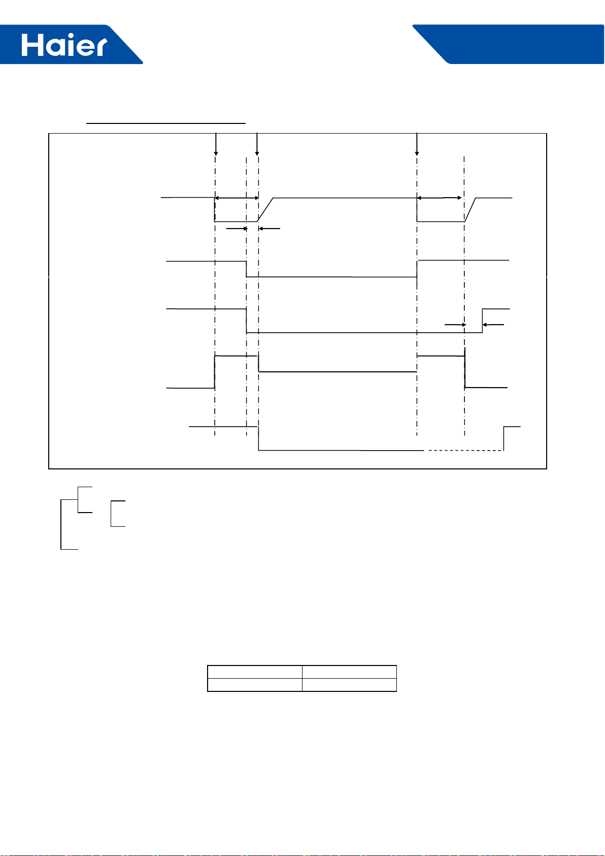
100
FlexFit Pro
6.2.5 EEV control:
1. Set one general EEV on outdoor unit board, control the EEV by indoor unit, outdoor unit board is regarded as
executing agency.
(1) Reset the electrify valve: act one full-closed action when the first electrifying of the outdoor valve board.
(2) Power source: switch power source, outdoor unit 13.5V (input voltage of the EEV) are the same line.
2. The electronic property of the EEV
Largest opening 500 pulse
Driving speed PPS
Remark: considering the application of MAXI, the EEV of each model should be larger, when operating as one
outdoor unit with one indoor unit, the opening of the EEV should be stable lower than 200 steps. Leave the system
adjustment margin of MAXI.
3. The initialization action of the EEV.
Driving speed of the EEV: Open-way: 31.25 PPS (32MS) , Closed-way: 31.25 PPS (32MS)
full open action and full closed action of EEV: full open action: open as 470 pulse (E) , full closed action: after
closing 540 pulse, repeat three times (close as 60 pulse and open as 5 pulse, it means stop at opening of 5)
Process control chart of oil return:
Send oil return signal Start End
Inverter comp. Indication frequency 60s Oil return frequency A Hz (E) 60s Soft
Starting
0HZ 0HZ
5s
OD fan auto Auto
Auto adjustment according to cooling mode
4-way valve ON
OFF 25 s
450pulses 450pulses
300pulses (E)
OD expansion valve auto opening Auto opening
IN fan ON
OF Cold wind prevention mode start
OR
OR
The longest 9 minutes
Td-TC<20°C lasts 30 minutes (it will start to judge after oil return lasting 30 seconds.)
Ts-TM<15°C lasts 30 minutes (it will start to judge after oil return lasting 30 seconds.)
The shortest running 3 minutes
101
FlexFit Pro
4. The limitation of the EEV opening
Condition Opening Requirement Lower Limit Upper Limit
Shut down Standard opening of the model, according to the
opening of last time / /
Standby
(temperature sensor off)
Standard opening of the model, according to the
mode before the temperature sensor is off / /
Cooling startup process Execute the standard cooling opening of the model Standard opening 400
Heating startup process Execute the standard heating opening of the model 150 400
Cooling, dehumidification Adjust automatically 70 470
Heating Adjust automatically 70 470
Defrosting Fixed opening 200 400
Oil return Fixed opening 150 400
Refrigerant discharge Fixed opening 150 400
6.2.6 Control of shutdown
1. Initiative shutdown mode (shutdown normally without protection)
When the air conditioner is in cooling or heating mode, the compressor get the shutdown signal, the current
frequency of the compressor is more than 55HZ (EE) , the compressor will decrease to 48HZ at the speed of
2HZ/s and shut down directly.
If the current frequency of the compressor is lower than 55HZ, it will shut down directly after it receives the
signal. Avoid that the sudden shutdown will cause too strong stress when in high working frequency.
After the compressor stops, the fan motor will execute the left heat blowing and then stops.
Shutdown because of the anti-freeze protection, the compressor will stop as initiative shut down mode/
2. Passive shut down mode (Error protection shut down)
When the system come to the pressure protection, over-current protection, high module temperature protection,
high condensation temperature protection and the unit shut down, no matter the frequency of the compressor
come to 55HZ, the unit will shut down directly.
6.2.7 Defrosting control in heating mode
During heating a need for defrost is detected by the outdoor coil temperature sensor, and defrosting is controlled by
the ambient and coil temperature sensors.
1. Initiate defrost:
1) After compressor running in heating for continuous 10 minutes (E) and for accumulated 50 minutes (E) , by
testing Te (defrosting temp sensor) or TC (testing of outdoor exchanger frosting condition) and outdoor ambient
temp sensor TA, when it meeting the following condition for continuous 5 minutes, the unit will enter defrosting
operation. In case of no defrosting operation caused by imbalanced refrigerant ow (caused by refrigerant lack or
other reason) , the unit will enter defrosting when any one of the two conditions are meet.
Entering condition:
Te≤C×TA-α OR TC≤C×TA-α and lasts for 5 minuts
Note: C:
TA<0°C, C=0.8
TA≥0°C, C=0.6
a. Entering temp. limit of defrosting 1: -15°C≤C×TA-α≤-2°C
b. Entering temp limit of defrosting 2: C×TA-α<-15°C & Te≤-15°C for continuous 5 minutes & accumulated
running time reaching 90 minutes.
c. Defrosting entering limit condition: indoor coil temp lower than 40 degree
d. Heating mode compressor running accumulated time stop/pause condition:
Detecting stop (end) : shifting from heating to cooling mode
Detecting pause: thermostat OFF, unit off.

102
FlexFit Pro
4. When shifting from heating to other modes, four way valve will power off after a while.
5. 4-way valve protection:
In heating mode, after continuous running of compressor for 10 minutes, if Tm (indoor sensor) < indoor ambient
temp -2°C (E) and Te (outdoor sensor) >15°C (E) for continuously for 1 minute, four way valve will be powered
off, reporting four way valve error. If the compressor starts after 3 minutes and the error is detected 3 times
continuously in 1 hour, a 4-way valve error code will be displayed. The error will not be detected during defrost
and within 10 minutes after termination of defrost, in the oil return mode, or within 10 minutes following an oil return
cycle.
6. Only in initial starting of compressor in heating mode, outdoor fan motor and four way valve will powering on
simultaneously.
7. If compressor frequency is higher than regulated frequency before off, it will lower to required frequency and then
stop.
8. Compressor inverter frequency and outdoor fan speed will operate in accordance with other requirement.
6.2.8 Four way valve control:
1. When powering on, four way valve is in OFF state.
2. In other modes except heating, the four way valve is powered off.
3. The 4-way valve is on in the heating mode, except under the following conditions:
1) in heating mode, in initial starting time of compressor to ensure the pressure difference ;
1) in defrosting operation:
a, if there is no compressor stopping, power four way valve off;
2. Defrosting end contition:
After defrosting condition starts, it will last no more than 10 minutes (E) . Using Te to test outdoor heat exchanger
frosting condition, if it lasts over accumulative 60 seconds of 7°C (E) or over accumulative 30 seconds of 12°C (E)
or over 15°C (E) , defrosting will stop.
3. Forced defrost:
Starting condition of forced defrosting: in heating operation (including standby state) , unit will start forced
defrosting after receiving forced defrosting signal by indoor.
Indoor manual defrosting signal will keep until outdoor enters defrosting.
Note: It can enter manual defrosting when compressor in OFF state, but it needs to follow 3-minute protection
rule.
4. Timing defrosting mode condition:
Starting condition: after setting outdoor function dip switch, it will execute timing defrosting in heating mode.
A. If outdoor ambient temp is over 10 degree (E) , even if timing defrosting is set, it will follow the auto defrosting
condition, meaning auto entering and auto quitting.
B. When outdoor ambient temp is lower than 10 degree (E) (including 10 degree ) , it will follow the defrosting
operation as below:
When compressor runs for continuous 10 minutes (E) and runs for accumulative 50 minutes (E) , it will enter
defrosting operation.
C. Timing defrosting operation and quit condition is the same as auto defrosting.
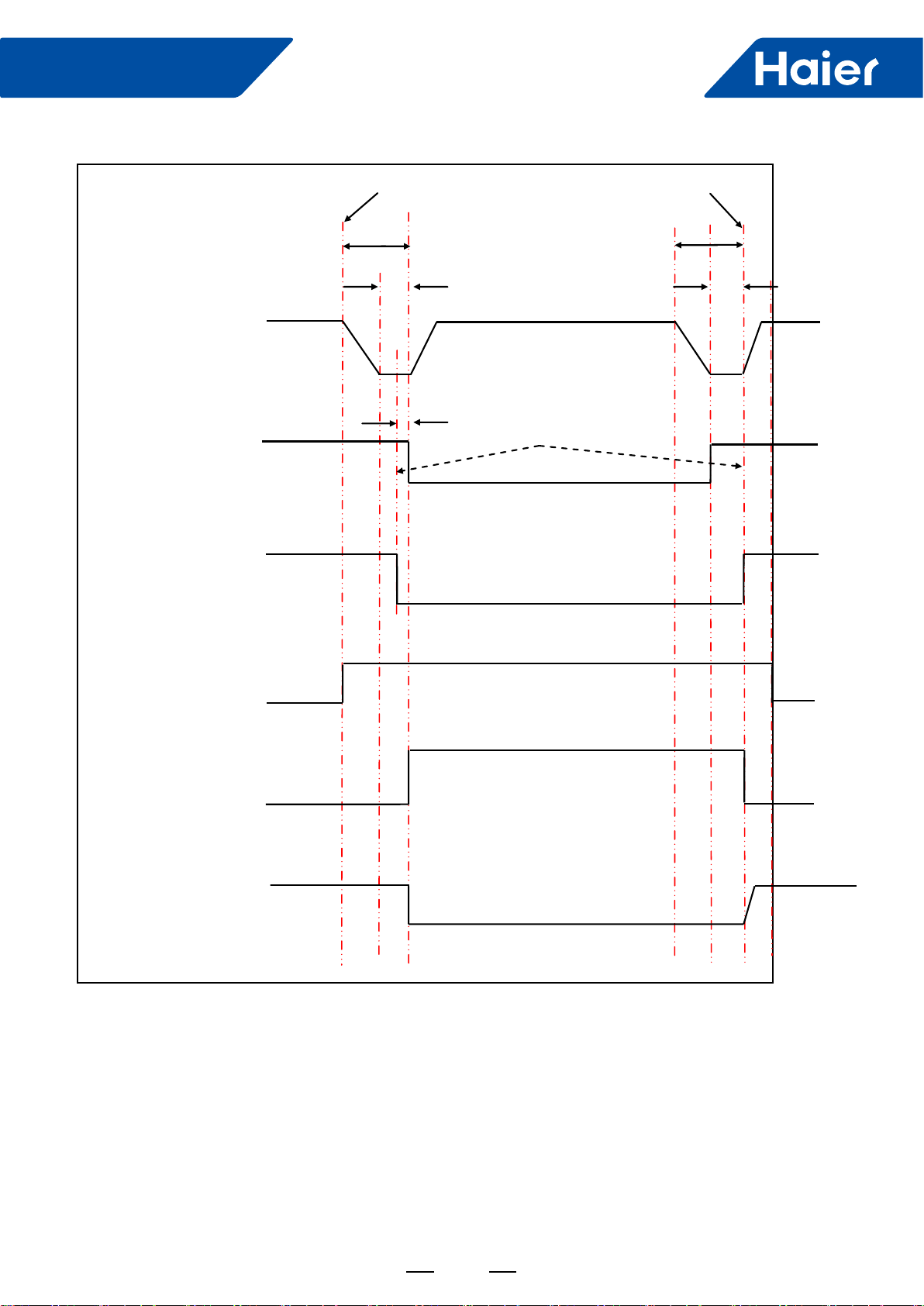
103
FlexFit Pro
Defrosting time sequence is as follows
Beginning END
60S 60S
30S 30S
Inverter compressor Defrosting FQYH Soft startup
10s
Outdoor fan motor ON Send signal to indoor uni ON
OFF
4-way valve ON ON
OFF
ON
Unload valve SV1 Auto
Open angle (E)
PMV Auto open angel
Anti-cold air function
Indoor fan motor ON
OFF
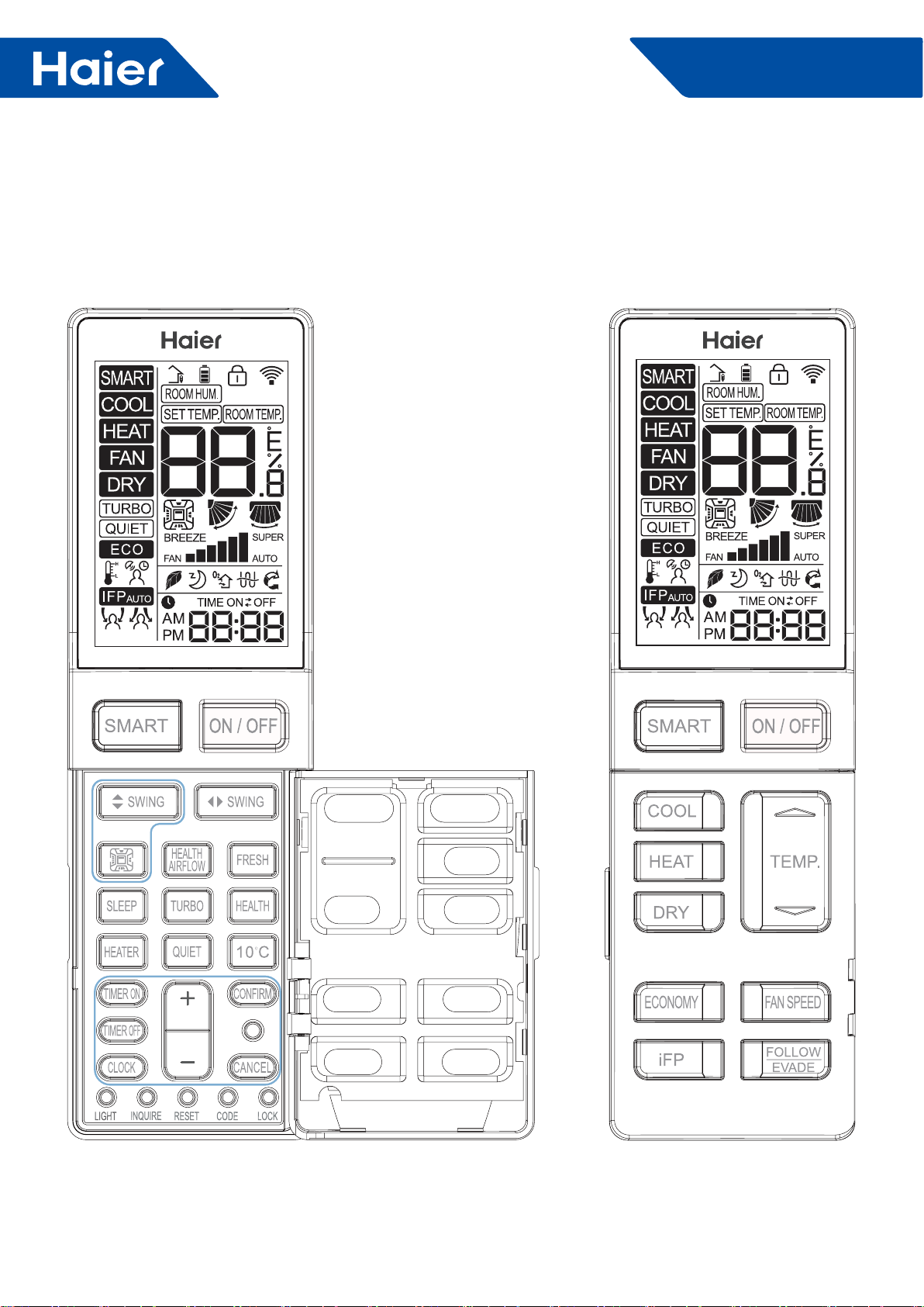
104
FlexFit Pro
7. Controller
External View of Remote Controller
7.1 Remote Controller: YR-HBS01
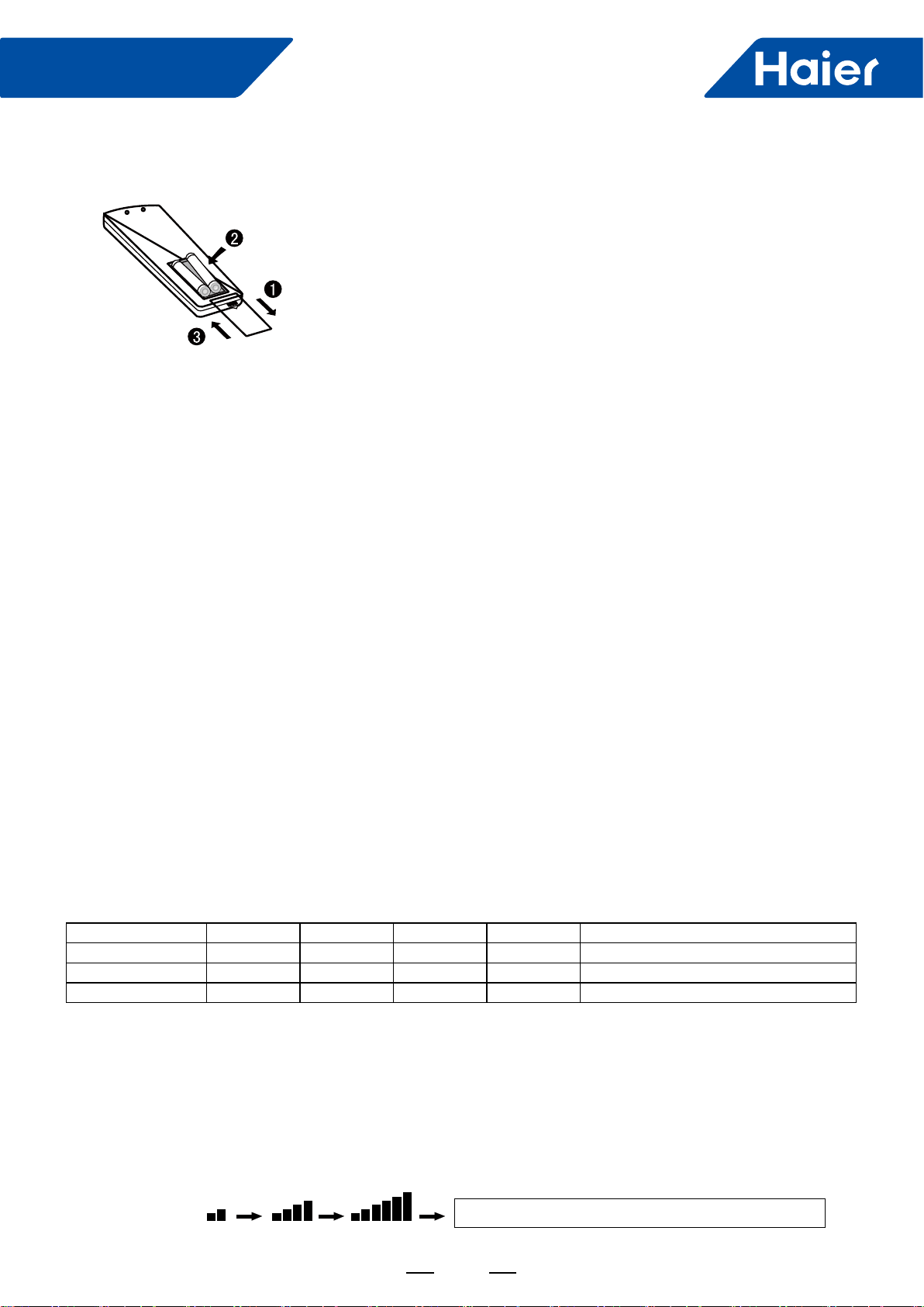
105
FlexFit Pro
Loading of the battery
Functional description:
1.Remove the battery cover
2.Insert 2 AAA batteries as illustrated noting battery polarity
3.Reinstall the battery cover
LOW, MED and HI fan speed circulate automatically
1. Power-up and Show All: the LCD display shows all symbols in this function. 3s later, it just shows time and the
initial time is AM 12:00. The initial time is adjustable and will be conrmed automatically 10s later.
2. ON/OFF Button: press the button for power on. The initial default mode is SMART, otherwise it will be the mode
before power OFF. Press OFF button after power on.
3. SMART Button:
(1) SMART button is always valid during power ON/OFF;
(2) Press SMART button to execute power OFF in SMART mode;
(3) In OFF and other modes, press SMART button to enter initial default setting of SMART mode. LCD setting
temperature is not showed;
(4) In SMART mode, press TEMP. +/- button to show the setting temperature.
4. COOL Button, HEAT Button and DRY Button
(1) When the remote controller in ON, press COOL button, HEAT button and DRY button to execute COOL mode,
HEAT mode and DRY mode.
(2) For initial power-up, temperature and fan speed will be showed as follows when entering each mode, otherwise
parameters set last time will be showed;
Mode SMART HEAT COOL DRY FAN
Initial TEMP. 24°C 24°C 24°C 24°C Setting temperature is not showed.
Mode SMART HEAT COOL DRY FAN
Initial Fan Speed AUTO LOW HI AUTO LOW
5. FAN Mode
(1) During power OFF, press "HEALTH" button or "FRESH" button to enter FAN mode with low fan speed.
Meanwhile, the HEALTH or FRESH icon will be showed on the screen.
(2) Temperature is not showed in FAN mode.
(3) Auto fan speed is not available when switching fan speed in FAN mode.
6. FAN SPEED Button:
(1) In other modes except for Fan mode, LOW, MED, HI and AUTO fan speed is adjustable, switching sequence is
as LOW-MED-HI-AUTO-LOW.
Note:
The distance between the signal transmission head and the receiver hole should be within 7m without any obstacle as well.
When electronic-started type fluorescent lamp or change- over type fluorescent lamp or wireless telephone is
installed in the room,the receiver is apt to be disturbed in receiving the signals,so the distance to the indoor unit
should be shorter.
Full display or unclear display during operation indicates the batteries have been used up. Please change batteries.
If the remote controller can't run normally during operation, please remove the batteries and reload several minutes later.
Hint:
Remove the batteries in case won't be in use for a long period. If there is any display after taking-out, just press reset key.
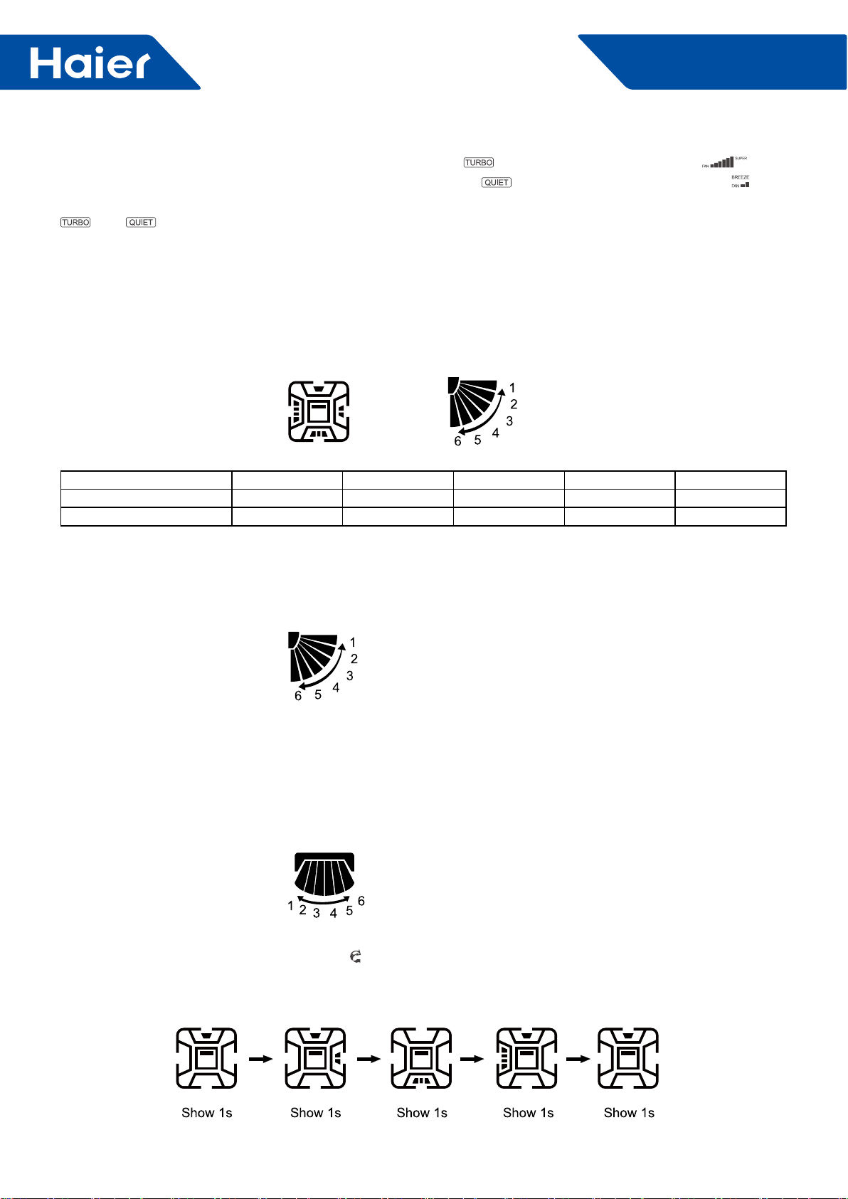
106
FlexFit Pro
(2) After TURBO or QUIET is set. Press TURBO button to show on the screen with fan speed as , then
press "FAN SPEED" button to exit; press QUIET button to show on the screen with fan speed as , then
press "FAN SPEED" button to exit. To cancel TURBO and QUIET, press TURBO and QUIET buttons respectively,
and icons will disappear and the fan speed will return to the last one.
(3) This button is invalid during power OFF.
7. TEMP. +/- Button:
(1) This button is invalid in FAN mode;
(2) Temperature adjustment range in SMART, HEAT, COOL and DRY mode: 16 ~30°C.
(3) Press and hold "TEMP. +/- " button, the temperature changes once; long press the button, the temperature
changes rapidly.
8. Four-side Embedment (Available for some models):
(1) Initial position of all modes for rst power on:
SMART HEAT COOL DRY FAN
Four-side Embedment Show all Show all Show all Show all Show all
SWING Angle Position 3 Position 5 Position 3 Position 3 Position 3
(2) After power on, press "Four-side Embedment" button for the rst time and the recycle approach is as follows:
four-side simultaneous control of Four-side Embedment → Four-side Embedment 1 → Four-side Embedment 2 →
Four-side Embedment 3 → Four-side Embedment 4 → Four-side simultaneous control of Four-side Embedment.
(3) When pressing "Four-side Embedment" button to select air deector, the selected air deector ashes. Press
"Up-and-down Angle" button to adjust angle of air deector at the moment.
9. Up-and-down SWING Angle:
1: Position 1; 2: Position 2; 3: Position 3; 4: Position 4; 5: Position 5; 6: Position 6 (reserved)
Recycle approach: Position 1→ Position 2→ Position 3→ Position 4→ Position 5→ AUTO→ Position 1
Free swing: 1→ 2→ 3→ 4→ 5→ 4→ 3→ 2→ 1 is showed circularly.
10. Right-and-left SWING Angle (Available for some models):
Recycle approach: 34 showed (Position 1)→25 showed (Position 2)→16 showed (Position 3)→1 showed (Position
4)→2 showed (Position 5)→ 5 showed (Position 6)→ 6 showed (Position 7)→ Auto swing
Auto swing approach: 1→ 2→ 3→ 4→ 5→ 6→ 5→ 4→ 3→ 2→ 1 are showed circularly.
11. HEALTH AIRFLOW (Available for some models):
Press "HEALTH AIRFLOW" button to show icon on LCD display. Each air deflector of swings on four sides
alternates circularly to indicate that the swing rotates to exhaust air. Meanwhile, up-and-down SWING angle shows
AUTO SWING. Press it again to cancel HEALTH AIRFLOW.

107
FlexFit Pro
12. SLEEP:
(1) Valid during power on.
(2) The SLEEP time is xed to 8 hours and is not adjustable.
(3) It is invalid in FAN mode. When setting TIMER ON or TIMER ON to TIMER OFF after setting SLEEP function,
once the timer setting is successful, the SLEEP function will be cancelled; after setting TIMER ON or TIMER ON to
TIMER OFF, the SLEEP function cannot be set. SLEEP function can be set from TIMER OFF to TIMER ON, TIMER
OFF and SLEEP function have priority in canceling the opposite side.
13. HEALTH:
(1) During power-on or power-OFF, press "HEALTH" button to display icon on LCD display, and press "HEALTH"
button again to cancel.
(2) During power-OFF, press "HEALTH" button to enter blowing-in mode, start low wind and HEALTH mode, display
icon .
(3) Switch among modes, and keep HEALTH function.
(4) If HEALTH function is set, power OFF and then on to stay in HEALTH mode.
14. ECO:
(1) Press ECO button and the display will show .
(2) ECO is valid under all modes, it is memorized among switch of all modes.
(3) ECO function power-on or power-OFF is memorized.
15. Turbo/Quiet:
(1) Press button "Turbo" display icon on remote LCD display, display icon of fan speed; Press button
"Quiet" display icon on remote LCD display, display icon of fan speed.
(2) Turbo and QUIET functions can not exist at the same time, the latter will replace the former.
(3) If Turbo function is set, press "SLEEP" button to exit turbo, which means that setting SLEEP function while
canceling turbo function. At the same time, the icon disappears and icon is shown; if QUIET function is set
at present, press button "SLEEP" while QUIET function is still kept.
(4) This function is valid under the mode of COOL or HEAT.
(5) Turbo/QUIET functions are not memorized among switch of all modes/the state of on or OFF.
16. IFP:
(1) Press "IFP" button, display , IFP function is set, and press "IFP" button again to cancel.
(2) Press "Follow/Evade" button, display that expresses following; press it again, display that expresses
evading.
Press it the third time to cancel.
(3) If follow/evade functions are set, air-out angle will change with position of people, so after setting these
functions, Four-side Embedment icons in all sides, up-and-down SWING and left-and-right SWING icons will
disappear.
(4) If air conditioner is in the state of HEALTH airow, follow/evade functions are set, HEALTH airow function is
cancelled, Four-side Embedment, up-and-down SWING and left-and-right SWING icons will disappear.
17. FRESH (available for some models):
(1) FRESH function is valid under the state of on or OFF. When air conditioner is OFF, press "FRESH" button,
display icon on LCD display to enter blowing-in mode and low speed. Press "FRESH" button again, this function
is cancelled.
(2) After FRESH function is set, on or OFF functions are kept.
(3) After FRESH function is set, mode switch function is kept.
18. 10°C Heating Function (available for some models) :
This function is valid only under the mode of HEAT, and it is not memorized under the state of on or OFF.
19. HEAT (available for some models) :
(1) When HEAT mode is chosen and is displayed on LCD display, pressing "HEAT" button can cancel and set
HEAT function.

108
FlexFit Pro
(2) Auto mode will not start HEAT function automatically, but can set or cancel HEAT function.
20. Timer:
(1) TIMER ON
• Press "TIMER ON" button, character "ON" is flashing, press "+/-" button to adjust, then press "OK" button to
conrm, if "OK" button is not pressed within 10 s, TIMER ON function is cancelled.
• If time of TIMER ON is the same as that of clock at present, character "ON" is always ashing and can not be
veried, it is necessary to readjust time.
• When the time of TIMER ON is end, the setting time and character "on" disappear.
(2) TIMER OFF
• Press "TIMER OFF" button, character "OFF" is ashing, press "+/-" button to adjust, then press "OK" to conrm, if
"OK" is not pressed within 10 s, TIMER OFF function is cancelled.
• If time of TIMER ON is the same as that of clock at present, character "OFF" is always flashing and can not
veried, it is necessary to readjust time.
• When the time of TIMER OFF is end, the setting time and character "OFF" disappear.
(3) TIMER ON/OFF
• After TIMER ON/OFF is set, remote will automatically judge sequential order of ON/OFF, arrow indicates that the
one performed rst points to the one performed second.
• After the time of clock performed rst is end, corresponding characters of timer "ON/OFF" disappear.
• If time of TIMER ON is the same as that of TIMER OFF, and can not be veried, corresponding character of the
latter of setting time is always ashing, it is necessary to readjust time and conrm again.
• If time of TIMER ON/OFF is the same as that of clock at present, and can not be verified, it is necessary to
readjust time and conrm again.
(4) After setting timer, display the setting of timer first and then display time all the time, when timer is active,
character "ON/OFF" is always displayed.
21. Button +/-:
• Press button "+/-" time will change in terms of 1 min as unit, pressing and holding the button will change quickly.
22. Clock:
• Press "Clock" button, "Morning" or "Afternoon" displayed at present are flashing to enter the state of clock
adjustment, adjust clock and then press "OK" to conrm.
• It is valid under the state of ON/OFF.
23. LIGHT:
• No display on remote controller LCD, which is processed by indoor unit.
24. RESET:
• Perform one power on reset operation when RESET button is pressed.
25. LOCK:
• Press button Lock, display Lock symbol on LCD display, buttons on remote controller can not be used, press
button Lock again to unlock.
26. CODE:
• Function reserved.
27. INQUIRE
• Processing by Indoor unit
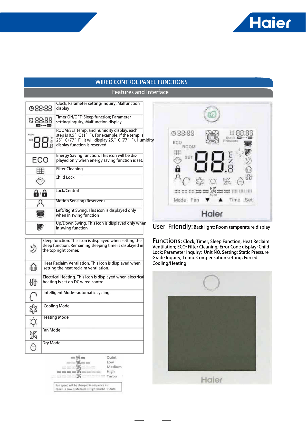
109
FlexFit Pro
7.2 Wired controller: YR-E17
ENGLISHSECTION E
User Friendly: Back light; Room temperature display Functions: Clock; Timer; Sleep Function; Heat Reclaim Ventilation; ECO; Filter Cleaning; Error Code display; Child Lock; Parameter Inquiry; Unit NO. Setting; Static Pressure Grade Inquiry; Temp. Compensation setting; Forced Cooling/Heating WIRED CONTROL PANEL FUNCTIONSSection E - Wired Controller YR-E17Features and InterfaceClock; Parameter setting/Inquiry; Malfunction displayTimer ON/OFF; Sleep function; Parameter setting/Inquiry; Malfunction displayROOM/SET temp. and humidity display, each step is 0.5°C (1°F). For example, if the temp is 25°C (77°F), it will display 25.°C (77°F). Humidity display function is reserved.Energy Saving function. This icon will be dis-played only when energy saving function is set.Filter CleaningChild LockLock/CentralMotion Sensing (Reserved)Left/Right Swing. This icon is displayed only when in swing functionUp/Down Swing. This icon is displayed only when in swing functionSleep function. This icon is displayed when setting the sleep function. Remaining sleeping time is displayed in the top right corner.Electrical Heating. This icon is displayed when electrical heating is set on DC wired control.Heating ModeFan ModeDry ModeHeat Reclaim Ventilation. This icon is displayed when setting the heat reclaim ventilation.Intelligent Mode--automatic cycling.Cooling Mode
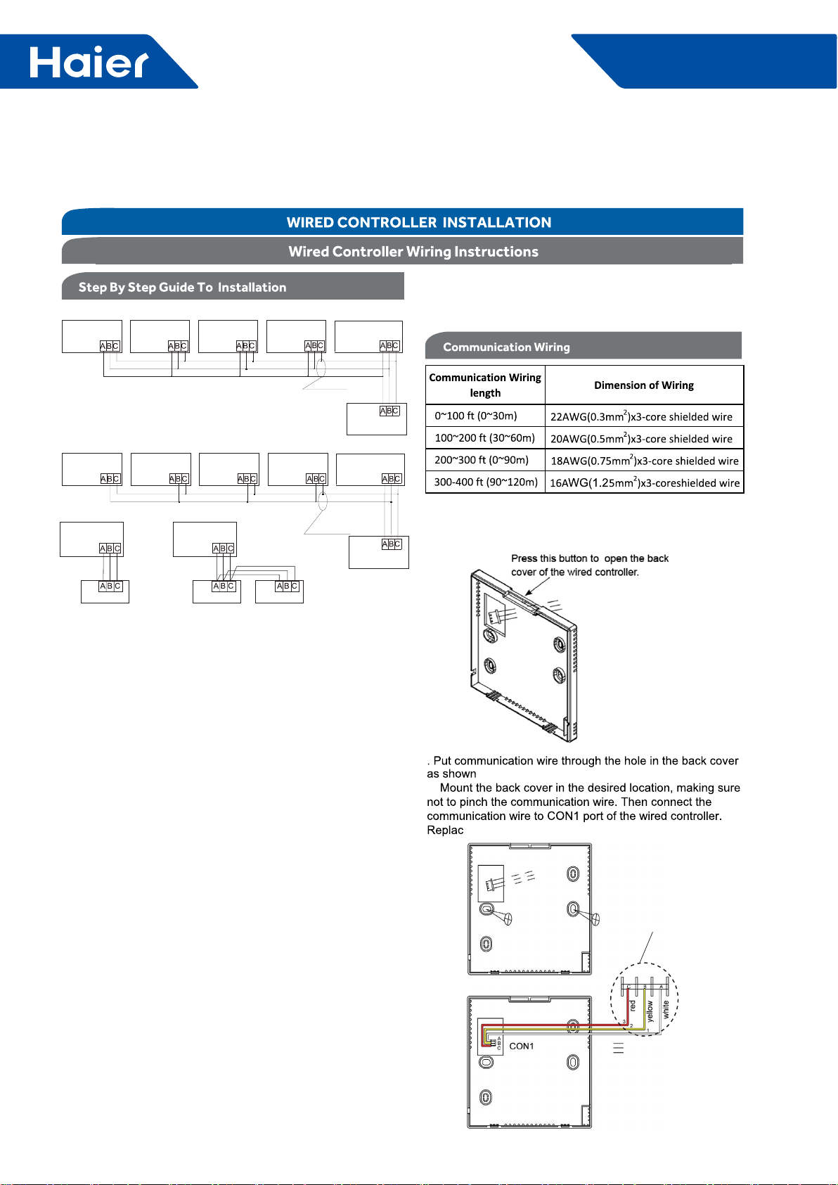
110
FlexFit Pro
There are three methods to connection wire controller and the indoor units:A: One wired controller can control max.up to 16 sets of indoor units, for Flexifit Pro series indoor units, there are two connection method:Type 1: for model AL24/36/42/48LP2VHA,AM24LP2VHA,the wiring connection between wired controller - the master unit (directly connected to the wired controller), master unit - slave unit, slave unit-slave unit should be one to one match of all three lines.Type 2: for model AM36/42/48LP2VHA,The wiring connection between wired controller-the master unit (directly connected to the wired controller) should be three polar wire, and the wiring between master unit - slave unit, slave unit-slave unit should be one to one match of two polar lines.Note: PCB DIP switches are used for setting slave units, please refer to indoor unit wiring diagram.B. One wire controller controls one indoor unit, and the indoor unit connects with the wire controller through 3 pieces of polar wire.C. Two wired controllers control one indoor unit. The wire controller connected with indoor unit is called master one, the other is called slave one. Master wire controller and indoor unit; master and slave wire controllers are all connected through 3 pieces of polar wire.Note: There are PCB DIP switches for slave or master units selection, please refer to the indoor unit wiring diagram to get details.About the wire:The wire controller is equipped with special communication wiring in the accessories. 3-core terminal (1-white 2-yellow 3-red) is connected with the terminal A, B, C of wire controller respectively.*One side of the shielded sheet of communication wire must be earthed.Indoor PCB port.
For location
number ,refer
to indoor unit wiring
diagram.
TYPE 2, FOR AM36/42/48LP2VHAA TYPE 1, FOR AL24/36/42/48LP2VHA, AM24LP2VHABCWire controller portWire controller portWire controller portWire controller portWire controller portWire controller control wiring of Wire controller(master unit)Indoor 1Indoor 2 Indoor N Indoor 15 Indoor16 (master unit)Indoor 1Indoor 2 Indoor N Indoor 15 Indoor16 Wire controller portWire controller portWire controller portWire controller portWire controller portWire controller control wiring of Wire controller Wire controller Polar wire Wire controller port wireWire controller port wireWire controller Wire controller Indoor 1Indoor 1The communication wiring is 189ft (4.8 meter) long; if the actual length is more than it, please distribute wiring according to below table:
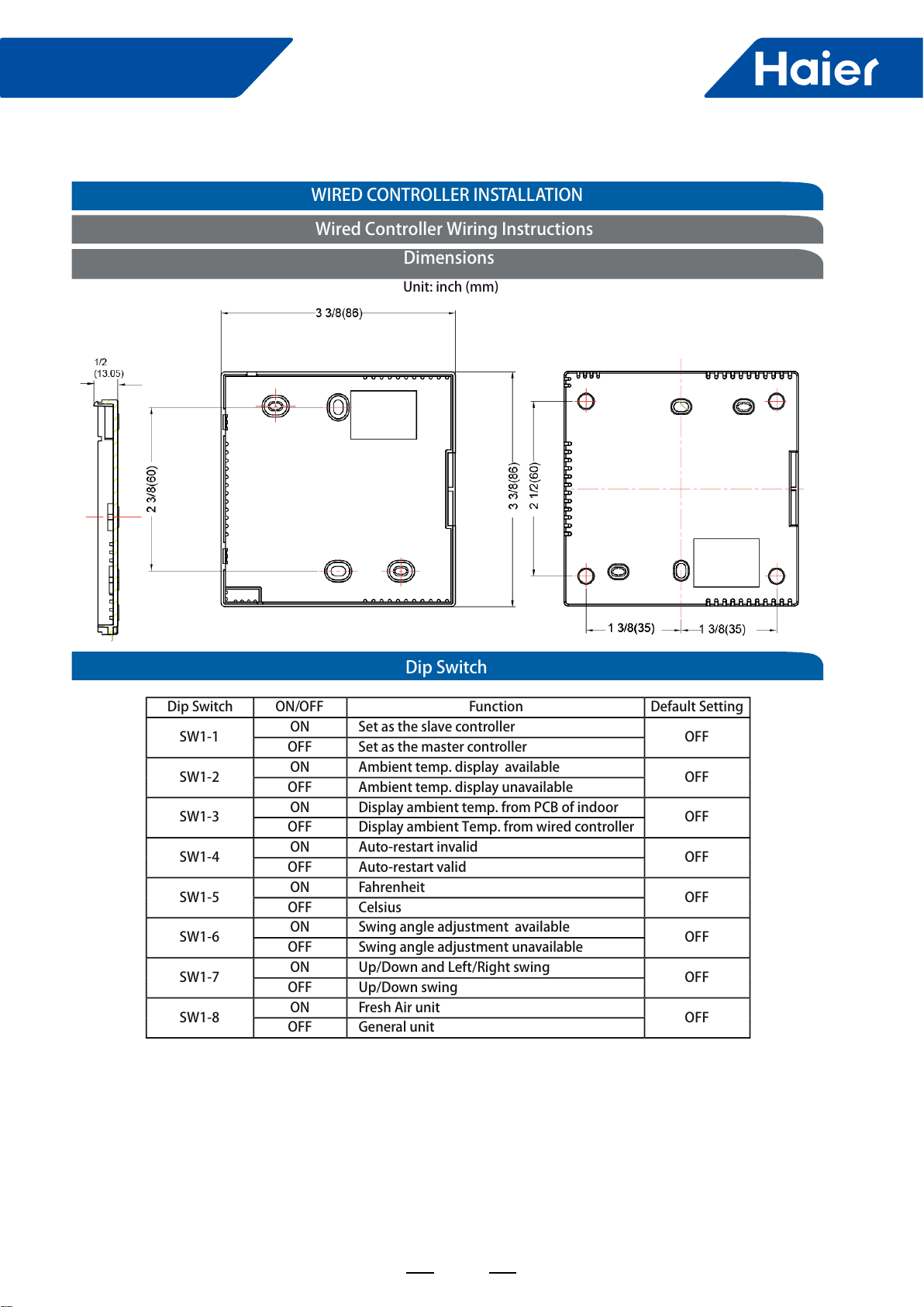
111
FlexFit Pro
ENGLISH
Dip SwitchWired Controller Wiring InstructionsWIRED CONTROLLER INSTALLATIONDimensionsUnit: inch (mm)Dip SwitchON/OFFFunctionDefault SettingSW1-1ON Set as the slave controllerOFFOFF Set as the master controllerSW1-2ON Ambient temp. display availableOFFOFF Ambient temp. display unavailableSW1-3ON Display ambient temp. from PCB of indoorOFFOFF Display ambient Temp. from wired controllerSW1-4ON Auto-restart invalidOFFOFF Auto-restart validSW1-5ON FahrenheitOFFOFF CelsiusSW1-6ON Swing angle adjustment availableOFFOFF Swing angle adjustment unavailableSW1-7ON Up/Down and Left/Right swingOFFOFF Up/Down swing SW1-8ON Fresh Air unitOFFOFF General unit
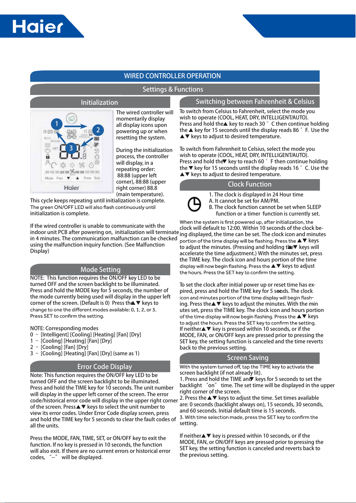
112
FlexFit Pro
ENGLISHSECTION E
WIRED CONTROLLER OPERATION123NOTE: This function requires the ON/OFF key LED to be turned OFF and the screen backlight to be illuminated. Press and hold the MODE key for 5 seconds, the number of the mode currently being used will display in the upper left corner of the screen. (Default is 0) Press the keys to NOTE: Corresponding modes0 – [Intelligent] [Cooling] [Heating] [Fan] [Dry]1 – [Cooling] [Heating] [Fan] [Dry]2 – [Cooling] [Fan] [Dry]3 – [Cooling] [Heating] [Fan] [Dry] (same as 1) Note: This function requires the ON/OFF key LED to be turned OFF and the screen backlight to be illuminated. Press and hold the TIME key for 10 seconds. The unit number will display in the upper left corner of the screen. The error code/historical error code will display in the upper right corner of the screen. Press keys to select the unit number to view its error codes. Under Error Code display screen, press and hold the TIME key for 5 seconds to clear the fault codes of all the units.Press the MODE, FAN, TIME, SET, or ON/OFF key to exit the function. If no key is pressed in 10 seconds, the function will also exit. If there are no current errors or historical error codes, “--” will be displayed. The wired controller will momentarily display all display icons upon powering up or when resetting the system. During the initialization process, the controller will display, in a repeating order: 88:88 (upper left corner), 88:88 (upper right corner) 88.8 (main temperature). This cycle keeps repeating until initialization is complete. initialization is complete. If the wired controller is unable to communicate with the indoor unit PCB after powering on, initialization will terminate in 4 minutes. The communication malfunction can be checked using the malfunction inquiry function. (See Malfunction Display)InitializationMode SettingError Code DisplaySettings & Functions1. The clock is displayed in 24 Hour timeA. It cannot be set for AM/PM. B. The clock function cannot be set when SLEEP function or a timer function is currently set.clock will default to 12:00. Within 10 seconds of the clock be-ing displayed, the time can be set. The clock icon and minutes keys to adjust the minutes. (Pressing and holding the keys will accelerate the time adjustment.) With the minutes set, press the TIME key. The clock icon and hours portion of the time keys to adjust To set the clock after initial power up or reset time has ex-pired, press and hold the TIME key for 5 seconds. The clock -ing. Press the keys to adjust the minutes. With the min-utes set, press the TIME key. The clock icon and hours portion keys If neither key is pressed within 10 seconds, or if the MODE, FAN, or ON/OFF keys are pressed prior to pressing the SET key, the setting function is canceled and the time reverts back to the previous setting. screen backlight (if not already lit). 1. Press and hold the TIME and keys for 5 seconds to set the backlight “on” time. The set time will be displayed in the upper right corner of the screen. 2. Press the keys to adjust the time. Set times available are: 0 seconds (backlight always on), 15 seconds, 30 seconds, and 60 seconds. Initial default time is 15 seconds. setting.If neither key is pressed within 10 seconds, or if the MODE, FAN, or ON/OFF keys are pressed prior to pressing the SET key, the setting function is canceled and reverts back to the previous setting.To switch from Celsius to Fahrenheit, select the mode you wish to operate (COOL, HEAT, DRY, INTELLIGENT/AUTO). Press and hold the key to reach 30 °C then continue holding the key for 15 seconds until the display reads 86 °F. Use the keys to adjust to desired temperature.To switch from Fahrenheit to Celsius, select the mode you wish to operate (COOL, HEAT, DRY, INTELLIGENT/AUTO). Press and hold the key to reach 60 °F then continue holding the key for 15 seconds until the display reads 16 °C. Use the keys to adjust to desired temperature. Switching between Fahrenheit & CelsiusClock FunctionScreen Saving
113
FlexFit Pro
ENGLISHSECTION E
NOTE: The display backlight must be illumi-nated before proceeding. To turn the back-light on, press any key (MODE, FAN, , TIME, or SET) located at the bottom of the display, or press the ON/OFF key located at the top of the display.Timer ONPress the TIMER key once, the ON timer icon will appear in the upper right corner of the screen. The ON icon and hour posi- keys to set the hour. Press the TIMER key again, the ON icon and minutes position are keys to set the minutes. Press the Timer OFFPress the TIMER key 3 times, the OFF timer icon will appear in the upper right corner of the screen. The OFF icon and hour keys to set the hour. Press the TIMER key again, the OFF icon and minutes position keys to set the minutes. Press Timer ON/OFFPress the TIMER key 5 times, the ON/OFF timer icon will ap-pear in the upper right corner of the screen. The ON icon and keys to set the hour. Press the TIMER key again, the ON icon and minutes position keys to set the minutes. Press the TIMER key again, the OFF icon and hour position are now keys to set the hour. Press the TIMER Press the keys to set the minutes. Press the SET key to ON) and adjusts the arrow direction accordingly. If neither key is pressed within 10 seconds, or if the MODE, FAN, or ON/OFF keys are pressed prior to pressing the SET key, the setting function is canceled and reverts back to the previous setting.Timer CancelPress the TIME key up to 9 times to cycle through the timer settings. When the timer icon disappears, the timer function is canceled.Note: An active timer function will remain displayed on screen until the set time has been reached and command completed. Timer Function SettingWIRED CONTROLLER OPERATIONSettings & FunctionsPress the SET key. The swing louver function icon will be displayed. Press the keys to advance through the functions to select ECO function. (The icon will icon will remain on.To cancel ECO function, repeat the above steps.NOTE: The energy saving default parameters are listed below:74°F Lowest temperature limit of Cooling and Dry mode.78°F Highest temperature limit of Heating mode.74°F – 86°F Temperature adjustment range in Cooling and Dry mode. 60°F – 78°F Temperature adjustment range in Heating mode.ECOFor CoolingUnder Cooling mode, set the temperature to 86°F. Press and hold the FAN key for 5 seconds. The Cooling ECO param-screen. Default temperature is 74°F. Press the keys to adjust the lowest target cooling temperature. Press the SET For HeatingUnder Heating mode, set the temperature to 60°F. Press and hold the FAN key for 5 seconds. The Heating ECO parameter screen. Default temperature is 78°F. Press the keys to adjust the highest target heating temperature. Press the SET Press and hold the SET and FAN keys for 5 seconds. The cur-rent static pressure will be displayed in the upper right corner Press the TIME key to shift the unit no. displayed in the upper left corner of the screen. The unit numbers are from 00-15.Press the keys to change the static pressure grade, shown in the upper right corner of the screen.setting. Press the MODE, FAN, or ON/OFF key to exit the function. If no key is pressed in 10 seconds, the function will also exit. NOTE: This function requires the ON/OFF key LED to be turned ON and the screen backlight to be illuminated. NOTE: This function requires the ON/OFF key LED to be turned ON and the screen backlight to be illuminated. NOTE: This function requires the ON/OFF key LED to be turned ON and the screen backlight to be illuminated. ECO Energy Saving FunctionECO Parameter SettingStatic Pressure Grade Inquiry & Adjustment
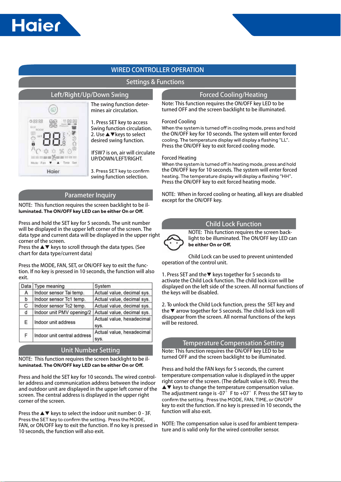
114
FlexFit Pro
ENGLISHSECTION E
WIRED CONTROLLER OPERATIONNOTE: This function requires the screen backlight to be il-Press and hold the SET key for 10 seconds. The wired control-ler address and communication address between the indoor and outdoor unit are displayed in the upper left corner of the screen. The central address is displayed in the upper right corner of the screen. Press the keys to select the indoor unit number: 0 - 3F. FAN, or ON/OFF key to exit the function. If no key is pressed in 10 seconds, the function will also exit.NOTE: This function requires the screen backlight to be il- Press and hold the SET key for 5 seconds. The unit number will be displayed in the upper left corner of the screen. The data type and current data will be displayed in the upper right corner of the screen.Press the keys to scroll through the data types. (See chart for data type/current data)Press the MODE, FAN, SET, or ON/OFF key to exit the func-tion. If no key is pressed in 10 seconds, the function will also exit.NOTE: This function requires the screen back-light to be illuminated. The ON/OFF key LED can Child Lock can be used to prevent unintended operation of the control unit.1. Press SET and the keys together for 5 seconds to activate the Child Lock function. The child lock icon will be displayed on the left side of the screen. All normal functions of the keys will be disabled.2. To unlock the Child Lock function, press the SET key and the arrow together for 5 seconds. The child lock icon will disappear from the screen. All normal functions of the keys will be restored.Note: This function requires the ON/OFF key LED to be turned OFF and the screen backlight to be illuminated.Press and hold the FAN keys for 5 seconds, the current temperature compensation value is displayed in the upper right corner of the screen. (The default value is 00). Press the keys to change the temperature compensation value. The adjustment range is -07°F to +07°F. Press the SET key to key to exit the function. If no key is pressed in 10 seconds, the function will also exit. NOTE: The compensation value is used for ambient tempera-ture and is valid only for the wired controller sensor. The swing function deter-mines air circulation. 1. Press SET key to access Swing function circulation. 2. Use keys to select desired swing function. If SW7 is on, air will circulate UP/DOWN/LEFT/RIGHT.swing function selection.Left/Right/Up/Down SwingNote: This function requires the ON/OFF key LED to be turned OFF and the screen backlight to be illuminated.Forced Coolingthe ON/OFF key for 10 seconds. The system will enter forced Press the ON/OFF key to exit forced cooling mode. Forced Heatingthe ON/OFF key for 10 seconds. The system will enter forced Press the ON/OFF key to exit forced heating mode.NOTE: When in forced cooling or heating, all keys are disabled except for the ON/OFF key. Forced Cooling/HeatingParameter InquiryChild Lock FunctionTemperature Compensation SettingUnit Number SettingSettings & Functions
115
FlexFit Pro
ENGLISH
Press the SET key. The swing louver function icon will be displayed. Press the keys to advance through the functions to select the SLEEP func- keys to set the will remain on.If neither key is pressed within 10 seconds, or if the MODE, FAN, or ON/OFF keys are pressed prior to pressing the SET key, the setting function is canceled and reverts back to the previous setting.To cancel the Sleep function. Press the SET key. The swing louver function icon will be displayed. Press the keys to advance through the functions to select the SLEEP function. function.NOTE: This function requires the ON/OFF key LED to be turned ON and the screen backlight to be illuminated. Sleep Functionthe indoor unit has reached 500 hours of operat-ing time.the icon and reset the operating time.NOTE: This function requires the ON/OFF key LED to be turned ON and the screen backlight to be illuminated. Filter CleaningWIRED CONTROLLER OPERATIONSettings & FunctionsPress the SET key. The swing louver function icon will be displayed. Press the keys to advance through the functions to select the Heat Reclaim To cancel the Heat Reclaim Ventilation function, repeat the above steps.If neither key is pressed within 10 seconds, or if the MODE, FAN, or ON/OFF keys are pressed prior to pressing the SET key, the setting function is canceled and reverts back to the previous setting.This function is reserved for future models.NOTE: This function requires the ON/OFF key LED to be turned ON and the screen backlight to be illuminated. Heat Reclaim VentilationNote: These functions require the ON/OFF key LED to be turned OFF and the screen backlight to be illuminated.Auto RestartSetting DIP switch SW1-4 located on the PCB of the wired control to the “on” position will disable the auto restart func-enabled (default position). When the switch is in the “on”posi-tion, auto-restart is disabled.Information retained in auto-restart are: Mode, Fan Speed, Temperature Setting, Swing State, and Heat Reclaim Ventila-tion function. Communication Error of Wired Controller If there is no communication between the wired controller and indoor unit for 4 minutes, when checking error codes, “07 will be displayed in the upper right corner of the display. Other Functions
116
FlexFit Pro
Appendix Sensor Characteristic
Model Sensor Name Part Code Charcteristic
AL24LP2VHA
AL36LP2VHA
AL48LP2VHA
AM24LP2VHA
AM36LP2VHA
AM48LP2VHA
Ambient temp. sensor 001A3900159 R25=23KΩ±3%
B25/50=4200K±3%
Indoor coil temp. sensor 0010401922 R25=10KΩ±3%
B25/50=3700K±3%
1U24LP2VHA
1U36LP2VHA
1U48LP2VHA
Defrosting temp. sensor 0010450194 R25=10KΩ±3%
B25/50=3700K±3%
Ambient temp. sensor 0010450192 R25=10KΩ±3%
B25/50=3700K±3%
Discharging temp. sensor 0010451303 R80=50KΩ±3%
B25/50=4450K±4%
Outdoor coil temp. sensor 0010451329 R25=10KΩ±3%
B25/50=3700K±3%
Sunction temp. sensor 0010451307 R25=10KΩ±3%
B25/50=3700K±4%

Haier Commercial Air Condition
Web: Http://www.haier.com
Haier reserves the right to make change without any notice.