LL_Dn°_A _ _NT-JAL Do Not Throw Away
......Operator's
Manual
Model No.
257.798031
05" Cutting Path)
)
•Always Wear Eye Protection During Operation
_k WARNING:
Read the Operator's Manual and
Follow All Warnings and S_d'ety
Instructions. Failure To Do SO
Ca_ Result in Serious Injury.' _i_:
SEA/,qS/CRI:lFTSMRNo
ELECTRIC TRIMMER
DOUBLE INSUI_TEI)
• Assembly
• Operation
• -Maintenance
:_068294_4-03/08/9t " * Sears,Roebuck and Co., 1991
ONE YEAR LIMITED WARRANTY ON CRAFTSMAN WEEDWACKER®
For One Year from date of purchese,when thisE|ectricLine THmmer ismainta_ned and _accordingtothe operatingand
m_ntenancc in_ructi'ons in the operator's manual, Seers will rep_ free of charge any defect in matem'al or workmanship.
This warranty excludesnylon llne or mayother partswhich areexpendableparts andbecomewornduring normalus_
If this Electric Line Trimmer is used for e_m_erclal or renbsL[ parposes, thi_ war,_anty applies for only 30 days from the date of pttrchase.
•WARRAN'I_ SERVICE IS AVAILABLE BY RETURNING THE UNIT TO THE NFAREST SEARS SERVICE CENTeR/DEPARTMENT IN
THE UNITED STATES. This warranbj applies only wh[le this pr_<Iuct is in use in the U_ited Ststes.
This warranty glv_ you specific legal rlghts, and you may al_o have other rights which vary from state to state.
SEARS, ROEBUCKAND CO. DEP_ D/731CR-W SEARS TOWER CHICAGO, IL 60684
TABLE OF CONTENTS
WARNINGS AND SAFETY INSTRUCTIONS ... 3
KNOW YOUR UNIT ........................5
A. Introdt_tion..........................5
B. Unpacking Instrnctions ................. 5
C. CartonContents.......................5
D. Double][nsuhtionConstruction..........5
ASSEMBLY ............................... 6
A. Assist Handle Attachment ............... 6
B. Tube Assembly ........................ 6
C. ShieldAttachment ..................... 6
D. Pre-0peration Checks .................. 7
E. Extension Cord Attachment ............. 7
EOperatingPosition.....................7
USING YOUR UNIT
A, Line Trimmer Safety ................... 8
B. Operating Instructions .................. 9
C. Adjustable Handle ..................... 9
D. Trimmer Line Advance .................. 9
E. Cutting Methods ....................... 9
E Line Rephcement ...................... 10
GENERAL MAINTENA.NCE
!L Malntemmve Safety.................... 11
B. Trouble Shooting Ctmrt ................. 11
ACCESSORIES ............................11
PARTS AND SERVICE ..............Back Cover
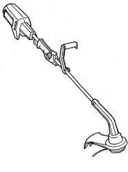
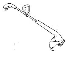
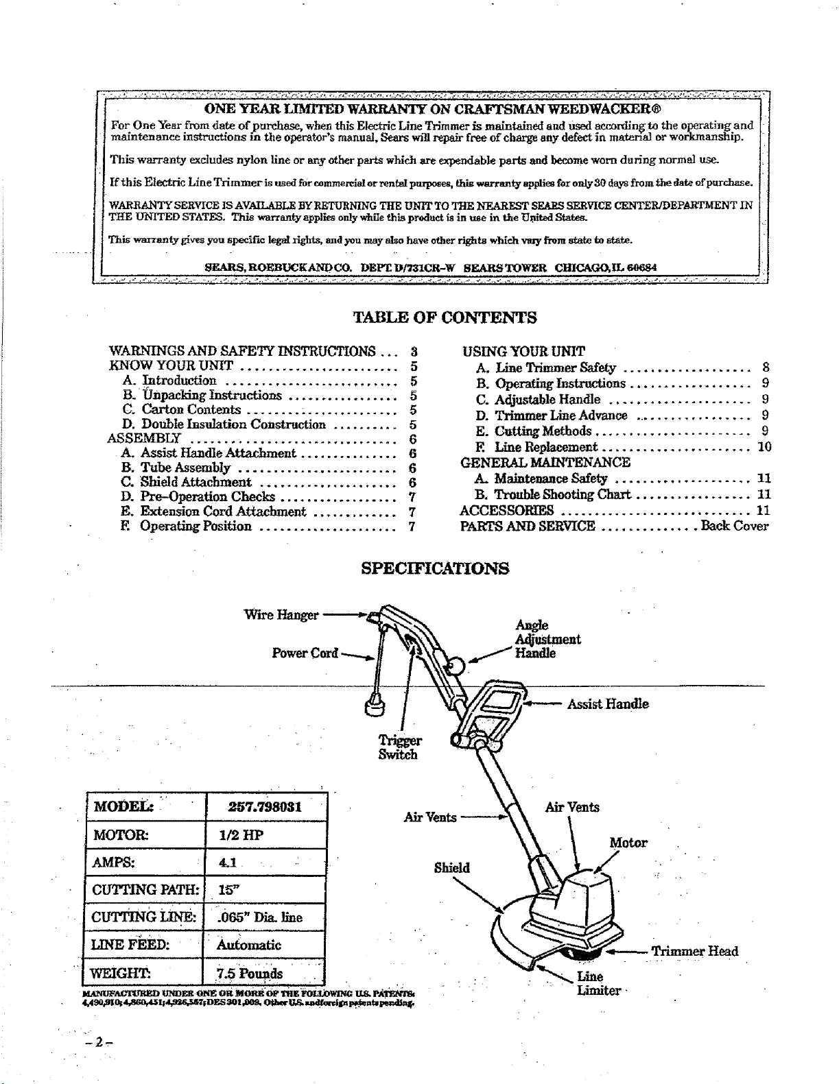
SPECIFICATIONS
V_rLreHanger
Power Cord
Assist Handle
AirVents
Shield
Air Vents
Motor
Limiter
A WARNINGS AND SAFETY INSTRUCTIONS
(See Additional Sa£ety Instructioi_s throughout this Manual)
_k WARNING- THISPOWER UNIT CAN BE DANGERO US! This unit can cause serious injury or
blindness to the operator aad others. When usingan electric trimmer, these basic safety precautions mat be followed to
reduce the risk ofinjary, fire, and electric shock. Failure to follow all instructions can result in blindness or other serious
injury. The operator is responsible for following the warnings and h_stractions ia this manual and on the unit. Read the
entire Operator's Manual before assembling and using this unit! Restrict the use of this unit to persons
who read, understand, and follow the wm'nings and instruchons in this manual and on the unit.
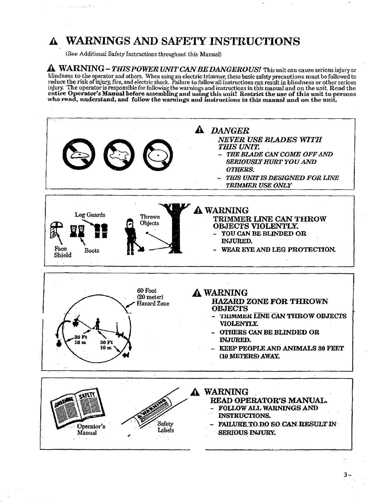
GOQ ADANGER
NEVER USE BLADES WITH
THIS UNIT
-THEBLADE CAN COME OFF AND
SEmO_SLY _VRT YOV A_'W
OTI_RS.
-7_s w_xs DESZGr,rEDFOR
TRIMMER USE ONLY
Face
Shield
_k WARNING
TRIMMER LINE CAN THROW
OBJECTS VIOLENTLY.
-YOU CAN BE BLINDED OR
INJURED.
- WEAR EYE AND LEG PROTECTION.
60 Foot _k WARNING
HAZARD ZONE FOR THROWN
OBJECTS
-"r_¢_I¢ LINE CAN THROW OBJECTS
VIOLENTLY.
-OTHERS CAN BE BLINDED OR
INJURED.
- KEEP PEOPLE AND ANIMALS 30 FEET
(10 METERS) AWAY.
Operator's Safety
Manual Labels
_k WARNING
READ OPERATOR'S MANUAL.
-FOLLOWALLWARNINGSAN_
• _STRUCIZONS.
- FAILURE.TO.DD SO. CA_. RESUL,T IN
SERIOUS.INJURY.
3_
V, _ARN[NGS AN D SAFETY INSTRUCTIONS ....(Continued)
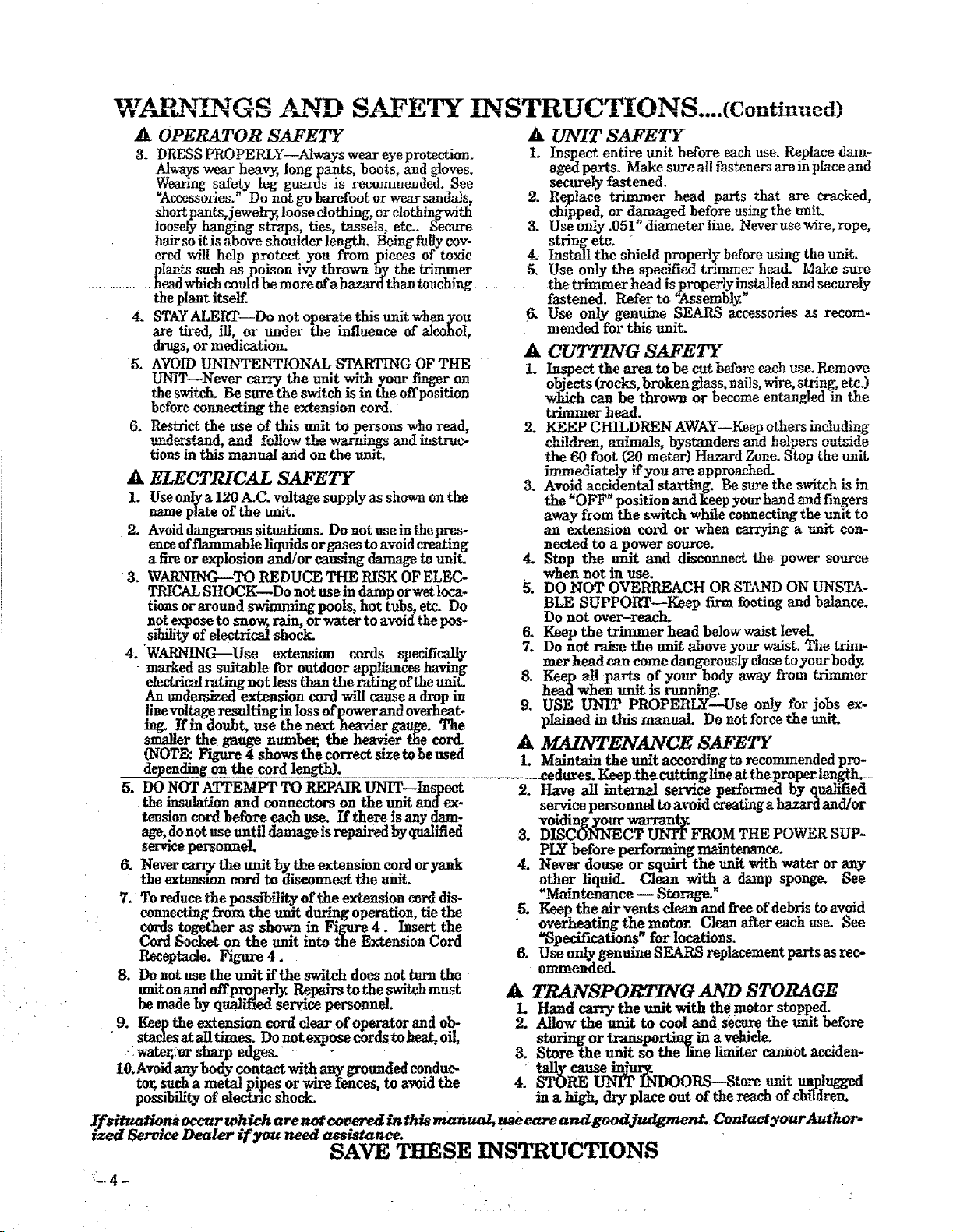
ik OPERATOR SAFETY _UNIT SAFETY
3. DRESS PROPERLY--Always wear eyeprotection. 1. Inspect entire unit before each use. Replace dam-
Always wear heav_, long pants, boots, and gloves, aged parts. Make sure all fasteners aye inplace and
Wea_'ng safer2( teg guards is recommended. See securely fastened.
_ccessories. Do not gobarefootorwearsandals, 2. Replace trimmer head parts that are cracked,
short pants, jewelry, loose clothing, or clothingwith chipped, or _ before using the unit.
loosely hanging straps, ties, tassels, etc.. Secure 3. Use only .051 diameter line. Neverusewire, rope,
hair so it is above shoutderlength, Being f_ly coy- sluing etc. •
ered will help protect you from pieces of toxic 4. Install the shield properly before using the unit.
plants such as poison i-_:ythrown by the _rimmer 5. Use only the specified trimmer head. Make sure
............... headwhich could be more ofahazard than touching .... .the trimmer head is_roperly installed and securely
the plant itself, fastened. Refer to _,ssembty.
Use only genuine SEARS accessories as recom-
mended for this unit.
4. STAYALERT--Do not operate this trait whan you
are tired, ill, or under the influence of alcohoI,
drugs, or medication.
5. AVOID UNINTENTIONAL STARTING OF THE
UNiT--Never carry the unit with your finger on
the switch. Be sure the switch is in the offposition
before connecting the extension cord.
6. Restrict the use of this emit to persons who read,
-,md_'_,and, and fo_ow the warm_ngsand _t_ac-
tions in this manual and on the unit.
_k ELECTRICAL SAFETY
1. Use only a 120 A.C. voltage supply as shown on the
name plate of the unit.
2- Avoiddangerous situations. Do not use i_n.thepres-
ence offlammable liquids orgases to avoid creating
afire or explosion and/or causing damage to unit.
3. WARNING--TO REDUCE THE RISK OF ELEC-
TRICAL SHOCK--Do not use in damp or wetloca-
tions or around swimming pools, hot tubs, etc. Do
not expose to snow, rain, or water to avoid the pos-
sibility of electrical shock.
4. WARNING--Use extension cords specifically
marked as suitable for outdoor appliances having
electrical mt'mgnot less than the rating ofthe unit.
An undersized e_, ension cord will cause adrop in
liaevoltage resultmgin loss ofpower and overheat-
lag. If in doubt, use the next heavier gauge. The
smaller the gauge number, the heavier the cord-
(NOTB: Figure 4 shows the correct size to he used
_dm_g on the cord length}.
5. DO NOT ATTEMPT TO REPAIR UN1T--Luspeet
the insulation and connectors on the unit and ex-
tension cord before each use. If there is any dam-
age, donot use untildamage is repaired by qualified
servicepersonnel.
6. Nevercarrytheunitby theextensioncordoryank
the extension cord to disconnect the unit.
7. To reducethepossibility oftheex_usioncorddis-
cenaectLugfrom the unit during operation, tie the
cards together as shown in Figure 4. hsert the
Cord Socket on the nnit into the Extension Cord
Receptacle. Figure 4.
8. Do not use the unit ffthe switch does not turn the
unitonandoffproped_ Repairs to the switch must
be made by quM_ed service personnel.
9. Keep the exte_ion cord clear of operator and oh-_
•statics at alltimes. Do not expose cords to heat, oil,
:wa ;:or sharp edges.
I0_Avoidanybodycontactwithany groundedconduc-
tor,suchametalpipesorwirefences,toavoidthe
possibilityofelectricshock.
ACUTTING SAFETY
1. Inspect the area to be cut before each use. Remove
objects (rocks, broken glass, nails, wire, string, etc.)
which can be thrown or become entangled in the
trimmer head.
2. KEEP CHILDREN AWAY--Keep others including
the 60 foot (20 meter) Hazard Zone. Stop the unit
immediately if you are approache&
3. Avoid accidental starting. Be sure the switch is in
the "OFF" position and keep your hand and fingers
away from the switch while connecting the unit to
an extension cord or when carrying a unit con-
nected to a power source.
4. Stop the unit and disconnect the power source
when not in
5_ DO NOT OVERREACH OR STAND ON UNSTA-
BLE SUPPOKT_Keep fn_a footing mad balance.
Do not over-reach.
6. Keep the trimmer head belowwaist Ievel.
7. Do notraisetheunitaboveyourwrist.The trim-
mer head can come dangerously close to your bod_:
8. Keep nli parts of your body away from trimmer
head whenuultisrunning.
9, USE UNIT PROPERLY--Use only for jobs ex,
pIained in this manual. Do not force the unit.
AMAINTENANCE SAFETY
1. Maintain the unit according to recommended pro-
servicepersonneltoavoidcreating a hazard and/or
voidin_gyoaryourwarranty.
3. DISCONNECT UNIT FROM THE POWER SUP-
PLY before performing maintenance.
4. Never douse or squirt the unit with water or any
other liquid.Clean with a damp sponge_ See
_Main_nance _ Storage. _
5. Keep the air vents dean and free of debris to avoid
•overheating the motor. Clean after each use. See
_Specifieations" for locations.
6. Use onlygenuineSEARS replacementpartsasrec-
ommended.
ATRANSPORTING AND STORAGE
I. Hand carry the unit with the motor stopped.
2, Allow the unit to cool and sbcure the unit before
storing or transporting in avehicle_
3. Store the unit so theline limiter cannot acclden-
tally cause injur_.
4. STORE UNIT INDOORS--Store unit unplugged
in a high, dry place out of the reach of children.
If situations ocvur .w_h are not eovered ln this manmd, usb eare and goodjudgr_ Contact your Authoro
ized Service Dealer if you need assistan_ ".
SAVE THESE INSTRUCTIONS
LIII nl p Inn n un I
ill,llll i i,ill
KNOW YOUR UNIT
aRia i iiii i i i/ [ iiiii Hi imm i n
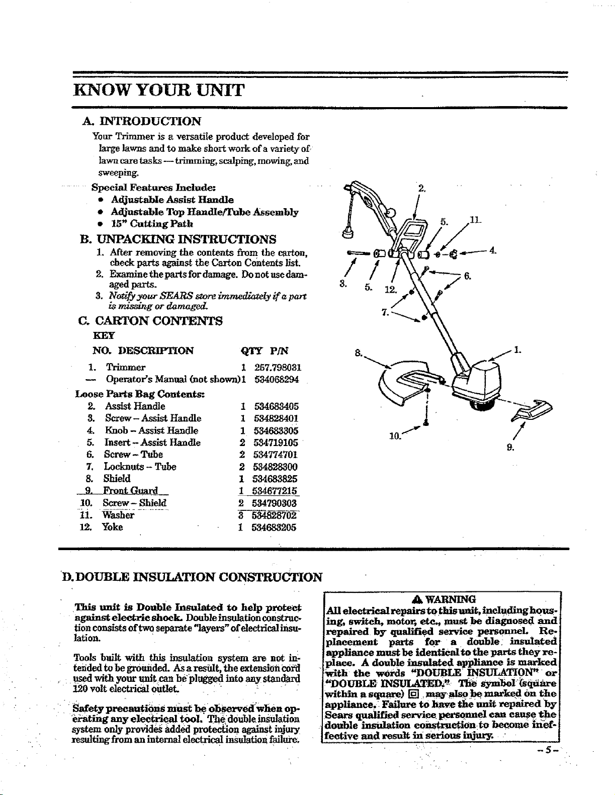
A. INTRODUCTION
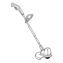
Your Trimmer is aversatile product developed for
large lawns and to make short work of a variety of,
lawn care tasks _ trimming, scalping, mowing, and
sweeping.
......... Special Features Include: ....
•Adjustable Assist Handle
oAdjustable Top Handle/Tube Assembly
•15" Cutting Path
B. UNPACKING INSTRUCTIONS
1. After removing the contents from the carton,
check parts ag_ins_ the Carton Co,tents fist.
2. Examine the parts for damage. Do not use dam-
aged parts.
3. No_fy your SEARS sZoreimmedlazely if a part
is rfdsdng or damaged.
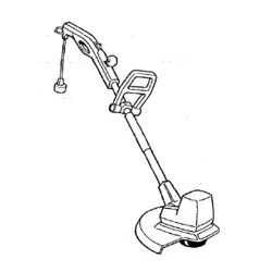
C. CARTON CONTENTS
KEY
NO. DES_ON QTY P/N
1. Trimmer 1 257.798031
Operator's Manual (not shown)l 534068294
Loose Parts Bag Contents:
2. Assist Handle I 534683405
3. Screw- Assist Handle i 534828401
4. Knob - Assist Handle 1534683305
5. Insert - Assist Handle 2 534719105
6. Screw-Tube 2534774701
7. Locknuts- Tube 2 534828300
8. Shield 1 _683825
9. Front G___uard_I _4677215
10. Screw-Shield 2534790303
12. Yoke 1 534683205
inl i iiiii i i] i i i
D.DOUBLE INSUlaTION CONSTRUCTION
This unit is Double Insulated to help protect
against eleetrie shook. Doublelnsulation construc-
tion consists of two separate "layers" of electrical insu-
lation.
Tools built with this insulation system are not in_
tei_ded to be gr0tmded. ASa r-_shlt, the extension €0_d
used with your trait =canbeplugged into any staudar d
_0 voltel_,t_i_ 0utlet, • "'.
' i i Safetypreeautiom must b¢.ob._ed'wlien otP
• lbi-ating any electrical tool, The.ld0uble insulation
system only provide_ added protec_on against injury
resulting from an internalelectrical insulationfailum_
AWARNING
All eleetriealrepairs t0this unit, incIudlnghouS
ing, switch, moto_ etc., must be diagnosed and
repaired by qualified service personnel Re-
placement parts far- a double: insulated
appliance must be identical to the parts they re'
place. A double insulated applianee is marked
_t]l _the wOi'ds "DOUBLE INSUI_TION'_ or
_"DOUBLE _INS_Di_ Tlie _sym_5ol_sqdare
within asquare) [], m_v._.:!_, marked Onthe
appliance.. FaiIure to have the unit repaired by
Sears qualified service personnel can cause the
double instdatlon eonstr, aetion:to bec_ae _ef-
feetive and result in serious _ry. :
ASSEMBLY
If your unit is received assembled, repeat all steps in this seetion to be sure assembly is correct and is
adjusted for the operator.)
PREPARATION
This Operator's Manualis designed to help you assembh a_d safely operate this u_it. It is important thatyou read the
entire manual to become familiar with the tool before you begin assembl_
TOOLS NEEDED FOR ASSEMBLY."
1. Phillips Screwdriver
2. AdjustableWrench
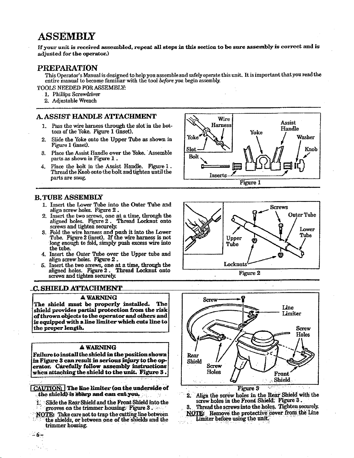
A. ASSIST HANDLE ATTACHMENT
I. Passthewireharnessthroughtheslot]nthebot-
tom oftheYoke.Figurei(inset).
2. SlidetheYoke ontotheUpper Tube as shown in
Figure1 (inset).
3. PlacetheAssistHandleovertheYoke. Assemble
partsasshowninFiguzeI.
4. PlacetheboltintheAssistHandle. Figurei.
ThreadtheKnob ontotheboltand tightenuntilthe
parts are snug. Figure1
ui ii i i ,i ,,,, ,H HHHI ,I ,I IIIIIr
B. TUBE ASSEMBLY
1. InserttheLower Tube intothe OuterTube and
align scre_r holes. Figure 2.
2. Insert the two screws, one at atime, through the
alignedholes.Figure2. Thread I.eclmutonto
screwsand tightensecurely.
3. Foldthewireharnessand push itintotheLower
Tube. Figure 2 {inset). Y_the wire harness is not
rlongenough to fold,simp!y push excesswireinto
thetube.
4. Insertthe OuterTube over the Upper tubeand
align screw holes.Figure2.
5. Insert the two screws, one at a time, thxough the
aligned holes. Figure 2. Thread Lo_-l_ut onto
screwsand tightensecurely.•
Lower
Tube
C=S.HT_,Ln A qMrACHMENT
A WARNING I
The shieId must be properly installed. The[
shield provides partial protection from the r_kI
of thrown objects _the o]_. rator and others mad [
iS equipped with a llne Iimiter which cuts line to ]
the proper length. I"
Screw------_y
Umiter
Screw
Holes
D.PRE-OPERATION CHECKS
I ........ A WARNING l
Review all Warnings and Safety Instructions in
this manual. '
L Before operating your tool, always:
a. Inspect the entire tool before each use. Re-
phce damaged parts. Make sure all fasteners arein
place and securely fastened_
f ,
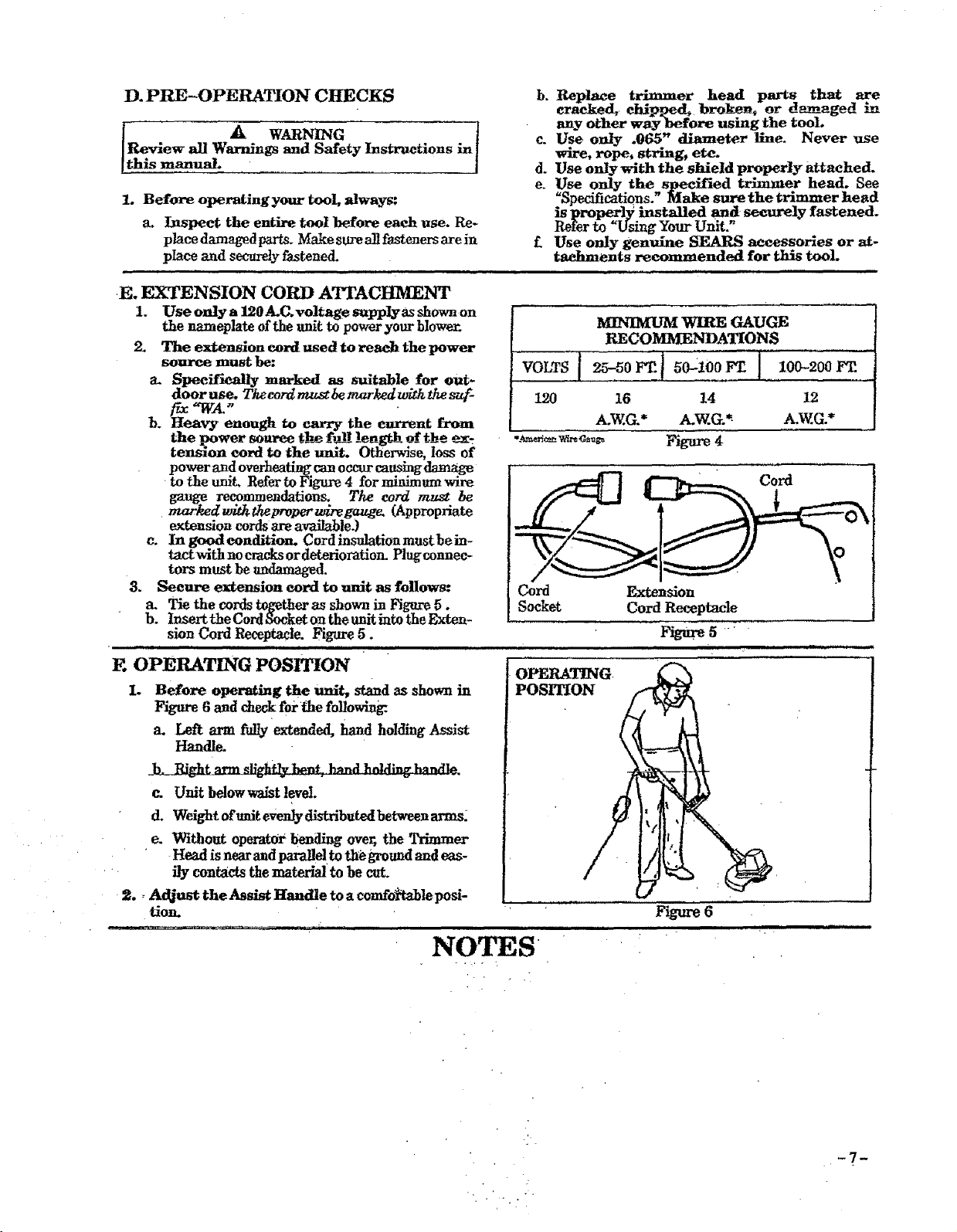
E. EXTENSION CORD ATTACHMENT
1. Use only a 120A.C,.voltage supplyas shownon
thenameplateoftheunittopoweryourblower.
2. The extension cord used to reach the power
source must be:
a. Specifically marked as suitable for out-
door use, Thecordmu_bemarkedwiththes_-
b. Heavy enough to carry the eur_nt from
the power source the f_ length of the ex-
tension cord to the unit. Otherwise, loss of
powerandoverheatingcanoccurcausing damage
totheunit,RefertoFigure4forminimum wire
gauge recommendations. The cord mu._t be
markedwithd_eproperwiregauge. (Appropriate
extensioncordsareavailable.)
c. In good condition-Cordinsulationmustbein-
tactwithnocracksordeteriorationPlugcoanee-
torsmust beundamaged.
3. Seeure extension cord to unit as follows:
Tie the cords together as shown in Figure 5.
b. InserttheCordSocketontheunitintotheExten-
sionCord Receptacle.Figure5.
., . i.,.,..i,.... iH i. H.
E OPERATING POSITION
I. Before operating the unit, stand as shown in
Figure 6 and check forthe f01_wln_
a. Leftarm fully extended,hand holdingAssist
Handle.
c_ Unit belowwaist level,
d. Weight of traitevenly dlstributed between arms2
e. Without operator bending over, the Trimmer
Head is nearandparalldto the groundandeas-
•. ily contactsthematerialto becut.
2., Adjust the Asslst Handle to acomfol_ablep0si-
tion. '
- ' ...... .....................NOTES
b. Replace t_mmer head parts that are
eracked, ehlpped_ broke_ or damaged
any other way before using the tool.
c. Use only .065" diameter llne. Never use
wire, rope, string, etc.
d. Use only with the shield properly attached.
e. Use only the specified trimmer head. See
"Specifications." Make sure the trimmer head
is proper13; installed and seeurely fastened.
Refer to "Using Your Unit.
£Use only genuine SEARS accessories or at-
taehments recommended for this tool
MINIMUM WIRE GAUGE
RECOMMENDATIONS
VOLTS I25-50 _ t _0--t00 F_ I
120 16 14
A.W.G.* A.W.G.*_
•.'__ _...-,c-.,.,_ Figure 4
100-200 FT.
12
A.W.G.*
....
Cord Extension
Socket Cord Receptacle
Figure5-_
OPERATING
POSmON
F m-e 6
,i i i
--7--
USING YOUR UNIT
ill
iii I iiIIIIIIIII I iiiiiiii iiiiii ii,i L, i
illill ,III,I,,,L,,,, iiiiii ill ,, ,i.,i ii
mi_ ,, i,,i,._i_mt. i iiUL,I U H H i
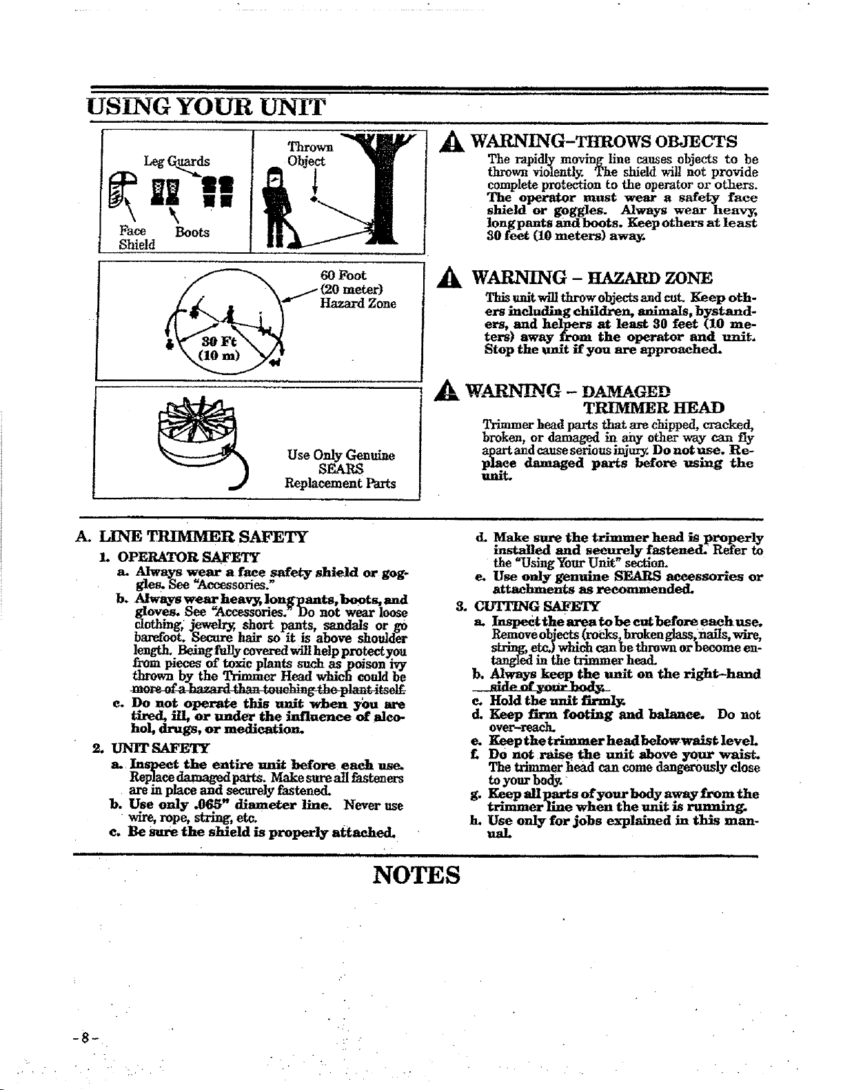
AWARNING-THROWS OBJECTS
The rapidlymoving linecausesobjectsto be
thrownviolently.The shieldwillnotprovide
complete protection to the operator or others.
The operator must wear asafety face
shield or goggIes. Always wear heav_
longpants and boots. Keep others at least
30 feet (10 meters) awa3_
60 Foot
(20 meter)
Use OnlyGenuine
SEARS
ReplacementParts
WARNING - HAZARDZONE
This unit will throw objects and cut. Keep oth-
ers including children, animals, bystand-
ers, and helpers at least 30 feet (10 me-
ters) away from the operator and unit.
Stop the unit if you are approached.
_, W.A31_G- DAMAGED
TRIMMER HEAD
Trimmer headpartsthatarechipped,cracked,
broken,or damaged in any otherway can fly
apartandcauseseriousinjury.Do notuse. Re-
place damaged parts before using the
unit.
A. LINE TRIMMER SAFETY
I. OPERATOR SAFETY
a. Always wear a face safety shield or gog-
gle s. See "Accessories."
b. Always wear heav_ longpants, boots, and
gloves. See "Accessories. _Do not wear loose
clothing; jewelry, short pants, sandals or go
barefoot. Secure hair so it is above shoulder
_t_nmgth.Being _fullycov_eredwill help protect you
pieces of toxic plants such as poison ivy
wn by the Trimmer Head which could be
e..Do not operate this uni't when you are
tired, ill or under the influence of alco-
hol, drugs, or medication.
2. UN1T SAFETY
a. Inspect the entire unit before each use.
Replace_ parts. Make sureallfasteners
areinplace and securelyfastened.
b. Use only .065" diameter line. Never use
wire, rope, string, etc,
e. Be Sure the shield is properly attached.
II
d. Make sure the trimmer head is p_t_perly
installed and securely fastened. Refer to
the "Using Your Unit" s_tior_
e. Use only genuine SEARS aceessorles or
attachments as recommended.
3. CUTHNG SAFETY
a. Inspect thearea tobe cut before eachuse.
Remove objects (roCks, broken glass, nails, wire,
string, etc.) which can be thrown or become en-
tangled in the trimmer head.
b. Always. keep the unit on the right-hand
md_ of yanr _.
e. Hold the unit firml3_
d. Keep firm footing and balance. Do not
over-reac_
e. Keep the trimmer head beIowwaist level
£DO not_ the unit above your waist.
The trimmer head can come dangerously close
toyour body.
g. Keep allparts ofyom- bod_y .away from the
trimmer llne when the unit Js running.
h. Use onIy for jobs explained in this man-
ual.
NOTES
-8_
B. OPE!_.TLNG _£RUCT!ONS
1. Bring the unit to full speed before entering
the material to be cut..
2. Always reIease the Trigger switch and allow
the unit to stop when not cutting.
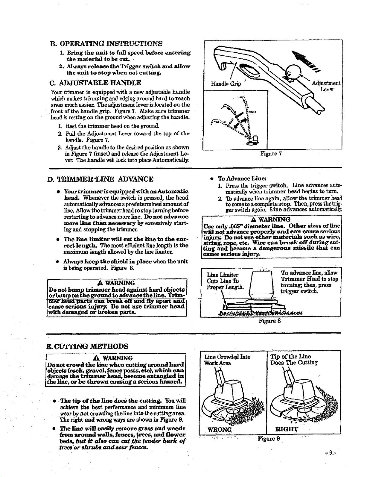
C. &DJUSTABLE HANDLE
Your trimmer is equipped with a yew adjustable handle
whic_ makes trimming and edging around hard to reach
area_ much easier. The adjustment lever is located on the
: front of the handle grip. F_ure 7. Make sure trimmer
head is resting on the ground when adjusting the handle.
LRest the trimmer head on the ground.
2. Pull the Adjustanent Lever toward the top of the
handle. Figure 7.
3. Adjust the handle to the desired position as shown
in Figure 7(inset) and release the Adjustment Le-
ver. The handle wil! lock i_to pIace Automatically.
Handle Grip Adjustment
Lever
Figure 7
D. TRIMMER-LINE ADVANCE
,YourtrimmerisequlppedwithauAutomati¢
head. Whenever the switch is pressed, the head
automatically advances apredetermined amount of
line. Allowthetrimmer head to stopturningbefore
restarting to advance more llne. Do not advance
more line than necessary by excessively start-
Lugand stopping the trimme_
e The line limiter will cut the llne to the cor-
rect length. The most effident line length is the
maximum length allowed by the line limitec
eAlways keep the shield in place when the unit
is being operated. Figure 8.
IAw GI ................"'i
[Do not bump trimmer head against hard objects |
]orbump on the ground to advance the line. Trim- '
"liner head parts can br6ak off and ny apart aria I
/cause serious _tur_ Do not use trimmer head[
]with damaged or broken _rts. I
•To Advance Line:
1. Press the trigger switch. Line adv_mces auto-
matically when trimmer head begins to turn.
2. To advance line again, allow the trimmer head
to cometo a eompl_eteStop. Then, press thetri'g-
gur switch again. Line advances automatically.
AWARNING
Use only ,1}65"diameter line. Other sizes of line
not advance properIy and _ _ sen?us
Do not ose other materials su_ as ware,
_rin_ rope,ere. Srxrecanbreakoffdu_g cut.
tmg b_adbecome a dangerous missile that can
cause serious injur_
t.;,,,.I,imiter _ TOadvan_line,allow
Lm---gToIItosup
_8
iiiii iiii, ......................
E.CUTTING iVlETHODS
A.w a . I
[Do.not crowd the llne when cutting around hard [
[objects .G-_pek2i_-avel, renew._osts, ere), which can [
laamage me trnmmer aeaa, _ecome entanglea m I
[the line, or be thrown eausmg a serious hitzard. [
•_-The tip of the Huedoes the cutting. You will
• achieve the best performance and minimum line
wear by not crowding theline into the cutting are_
The right and wrongways are shown in Figure 9.
t The Hue will easily remove grass mad weeds
from around walls, fences, trees, and flower
beds, but it also van cut the tender bark of
trees or shrubs and_s_zr fences.
Tip of the Line
Does The Cutting
ittoA! A WARNLNG
ways wear eye protection. Never lena over the
rimmer head. Rocks or debrls canricochet or]be
hrown into eyes and face and cause blindness or
ther serious in just.
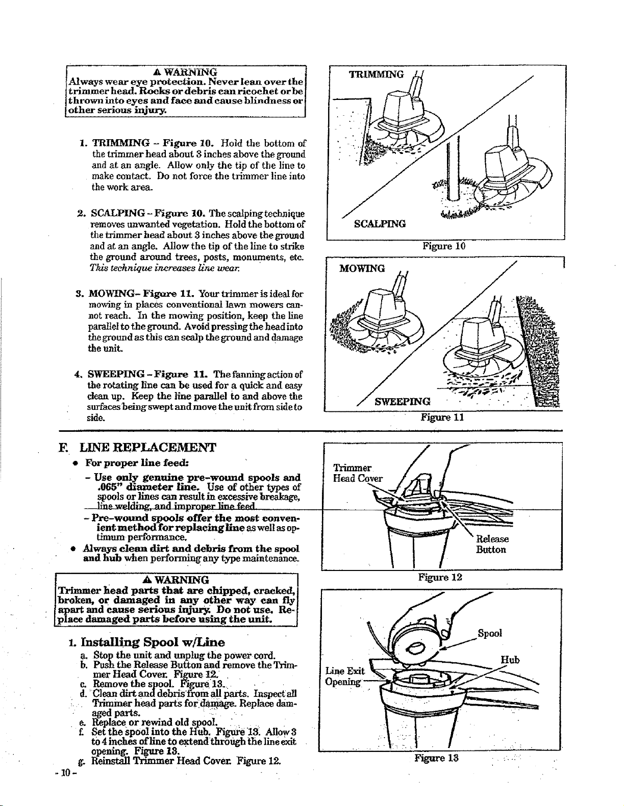
1. TRIMMING - Figure 10. Hold the bottom of
the trimmer head about 3inches above the ground
and at an angle. Allow only the tip of the line to
make contact. Do not force the trimmer line into
the work area.
4.
E
SCAI__PING- Figure 10. The scalping technique
removes unwanted vegetation. Hold the bottom of
the trimmer head about 3 inches above the ground
and atan angle. AIlowthe tip of the line to strike
theground around trees,posts,monuments,etc.
This technique increases llne wear.
MOWING- Figure 11. Your trimmer is ideal for
mooring in places conventional lawn mowers can-
not reach, tn the mowing position, keep the line
parallel to the ground. Avoid pressing the head into
the ground as this can scalp the ground and damage
the unit,
SWEEPING - Figure 11. The fanrdngaction of
the rotating line can be used for a quick and easy
clean up. Keep the line parallel to and above the
surfaces being swept and move the unit from side to
side.
LINE REPLACEMENT
•For proper line feed:
- Use only genuine pre-wound spools and
.065" diameter llne. Use of other types of
spoolsorlinescanresultinexcessivebreakage,
_dlng. and imprnrmrli_p_f__d........
-Pre-wound _ls offer the most conven-
ient method for replacing line as well as op-
timum performance.
• Always clean dirt and debris from the spool
and hub when performing any type maintenance.
pAWARNING I
Trimmer head parts that are ehlpped, cracked, I
broken, or damaged in any other way can fly]
apart and cause serious injur_ Do not use. Re-[
lace damaged parts before using the unit. [
1. Installing Spool w/Line
v- Stop the unit and unplug the power cord.
b. Push the Release Button and remove the Trim-
.mer Head Cove_ FigureL2i , .
c. Remove the spool Figttre13. . -.
d.Clean dirtand debriST_omallparts. Inspectall
' Trimmer head parts fori_, Replace dam-
parts, __:: ...
e_ R:eplace or rewind old spool :......
£_et thespool into theHub. Fi_ 13:Allow3
to 4 inches of line to extendthrSugh the line exit
opening. Figure 13. •
g. Reinstall Trimmer Head Cover. Figure 12.
- 10-
SCALPING
MOWING
T_m_er
Head Cover
Figure 10 l
Figure 11
Button
Figure 12
Spool
Hub
Hgure 18
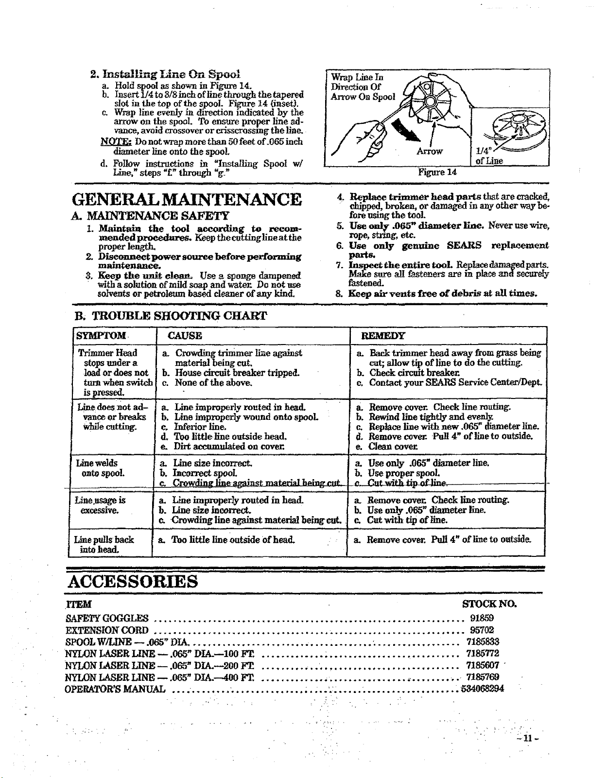
2, !nst_lIh-tg LLue On Spool
a. Hold spool as shown in Figure t4.
b. Insert 1/4 to 3/Sinch ofllne through the tapered
slot in the top of the spool. Fi_e 14 (inset).
c. Wrap line evenly in direction indicated by the
arrow on the spool. To ensure proper line ad-
vance, avoid crossover or crisscrossing the line.
Do not wrap more than 50feet of.065 inch
diameterlineontothespool.
d. Followinstructionsin "Ins•ailingSpool w/
Line," steps "_"through "g._
m,, ,,,,,, ,,,,,,,,,,,,, , , , ,
Wrap LineIn
DirectionOf
GENERAL MAINTENANCE
A. MAINTENANCE SAFETY
1. Maintain the tool aeeording to recom- 5.
mendedpr0eedmres. Keep the cuttinglineatthe
proper length_ 6.
2. Disconnect power so_ before performlng
maintenance, 7.
3, Keep the unit clean, Use a sponge damvened
withasolutionofmildsoapand water.Do notuse
so/vents orpetroleum based cleanerofany kind.
llll i ,,,,,,,,,,,,,,,,,,,,,,,,,,,,,,,,,,,,,,,,,, , l HIH ..
B. TROUBLE SHOOTING CHART
8_
,,,,,,,,,,,,,,,,,,
Arrow ofLine
Figure14
iiii H H iiiiii i
SYMP_M
Trimmer Head
stopsundera
toad or does not
turn when switch
is pressed,
Linedoes _ot ad-
vanceorbreaks
wMe cutting, e.
d,
e.
Linewelds a.
ontospool, b.
.... ,. j e_
Line.usageis a.
excessive, b.
J,,,,,,,, ,,,,
Linepulls back a.
into head,
Replace trimmer head parts tlmtarecracked,
chipped,broken,ordama_d inanyotherway be-
foreusingthetool.
Use o_r .065"diameter line.Neverusewire,
rope, string,etc.
Use only genuine SEARS repIacement
parts.
MIn_e_siLretheentire tool, Rephce_parts.
f.fastene__,_inph_ and secureIy
fastened_
Keep air vents free of debris at all times.
i ii i
cAUsE REMEDY "
a. Crowdingtrimmerline_ a. Backtrimmerheadaway fi-omgrassbeing
material being cat cut; allow tip of line to do the cutting.
b. House circuit breaker tripped, b. Check circuit breaker.
e. None of the above, c. Contact your SEARS Service Center/I)ept
a. Lineimproperlyroutedinhead. a. Remove cover.Checklinemuting.
b. Line improperly wound onto spool b. Rewind line tightly and evenly.
Iaferior line, c. Replace line with new .065_ diameter line.
Too llttlellne outside head. d. Remove cover. Pull 4" ofline to outside.
Dirt accumulated on cover, e. Clean cove_
Line size incorrect, a. Use only .065" diameter life.
hcorrect spool b. Use proper spool.
, ,,,,,,,,_.,, ................................ _ ...... .... , ,,,
&Remove cover. Check line muting.
b. Use only .065" diameter line.
Cut wlth tip of llne.
Remove cover. Pull 4" of line to outside.
Line improperly routed in head.
Line size incorrect.
Crowding line againstmaterialbeingcat.
J
Too littIe line Outside Ofhead.
i i i iii i j _'m""' ' iiii IIIIIIII iiiii iiiim i i ""m""' '_ .....;;, IIIIIIIII , ,, I I
ACCESSORIES
i,,,,,,,,,,i, ................... .ill .,i,,,111,1111iiii i .....
ITEM STOCK NO.
SAFE_ GOC_LES ................................................................ 91859
EXTENSION CORD ............................................................... . 95702
SPOOLW/LINE 065"DIA. 718_833
NYLON LASER LINE- 065"DIA.--100F'E 7185772
NYLON LASER LINE 065"DIA.--20OFE 7186607
NYLON LASER LINE -- .065"DIA.--400FT ............._................,........,. 7185769
OPERATOR'SMANUAL ..... ...... .534068294
- 11 -
operator's
manual
Model No.
257.798031
(15" Cutting Path)
How to Order
Repair Parts
SEARS SERVICE
is ATYOURSERVICE
The Model Number will be found below the top handle with the Serial
Number. Always mention the Model Number when requesting service or
repair parts for your unit.
A]Iparts listed herein may be ordered from any Sears Service Center and
most Sears Stores.
WHEN ORDERING REPAIR PARTS ALWAYS GIVE THE FOLLOWING
INFORMATION AS SHOWN IN THIS LIS_
• 1. The PART NUMBER
_. The MODEL NUMBER
257.798031
3. The PART DESCRIPTION
4. The NAME OF ITEM --
ElectrleTrinuner
ffthe parts you need are not stocked locally, your order will he transmitted
to a Sears Repair Parts Distribution Center for handling.
When you buy merchandise from
Seers you get an extra value tha_
nobody else can offer -- Sears
Service.
Acrosstownoracrossthecountry,
SearsServiceisalwaysnear;pro-
viding trustworthy,competent
servicetechniciansusing only
Sears specifmdfactory parts.
YourSears Merchandise takes on added value when you discover
that Sears has Service Units throughout the coaa_,. Each is
staffed by Seam-Trained. professional technicians using Searsap-
provedmethed_
Sold by Sears, Roebuck and Co., Chicago, Ill. 60684 USA L
534068294-4-03/08/91 i,i ,i ,,, , I,lIH,,p, tI* .......PmNTZ vm us_: