Loading ...
Loading ...
Loading ...
Section 4 - REPAIR & ADJUSTMENTS
4.1.7. AUGER SHEAR BOLT REPLACEMENT
IMPORTANT: If engine is operating correctly and
auger/impeller drive belt is not damaged or
severed, but the auger/impeller does not rotate it is
possiblythe auger/impeller shaft shear bolt.
1. Remove shear bolt and nut from auger. Discard
old shear bolt and nut. DO NOT reuse bolt or nut
under any circumstances. Always replace existing
hardware with genuine Snapper new replacement
shear bolts and nuts. DO NOT substitute these
shear bolts and nuts as auger/impeller and engine
damage can result.
2. Install new shear bolts and nuts. Tighten to 5 to
10 ft. lb. of torque. See Figure 4.12.
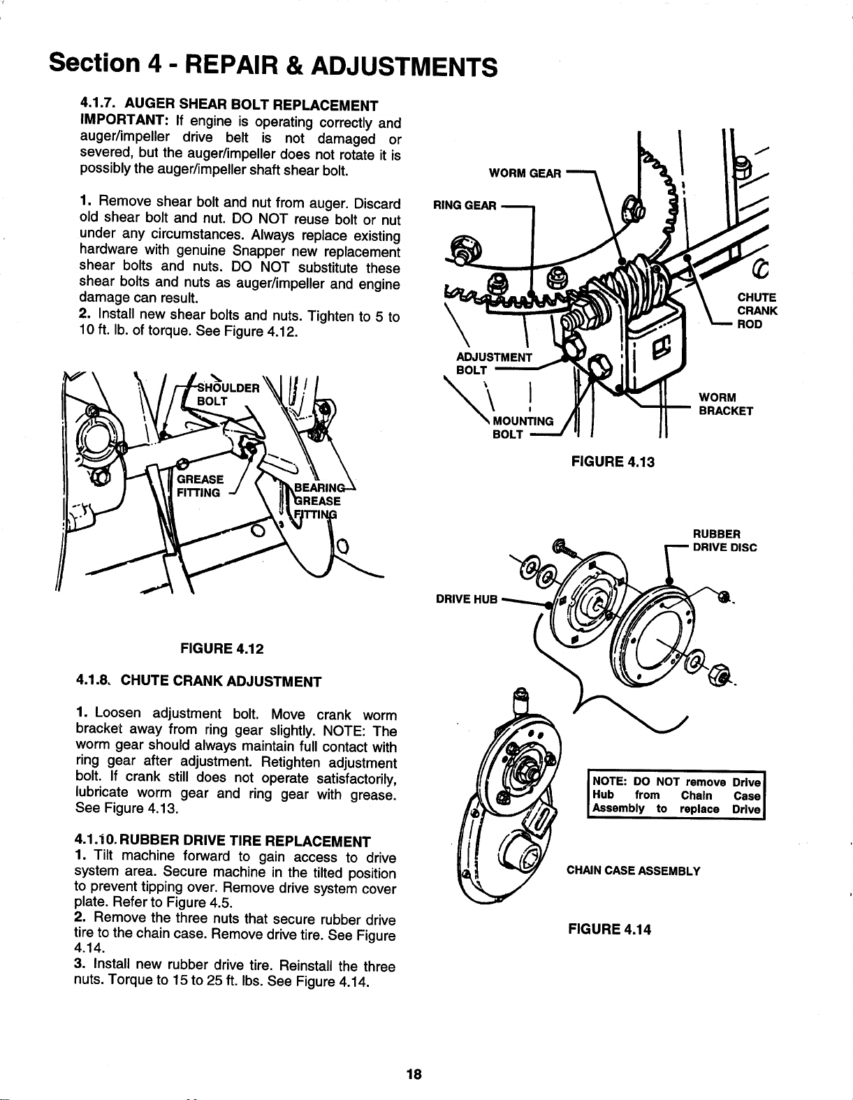
WORM GEAR
RING GEAR
\ADJUSTMENT
BOLT
_MOUN!ING
BOLT
FIGURE 4.13
CHUTE
CRANK
ROD
WORM
BRACKET
RUBBER
DISC
DRIVE HUB
FIGURE 4.12
4.1.8. CHUTE CRANK ADJUSTMENT
1. Loosen adjustment bolt. Move crank worm
bracket away from ring gear slightly. NOTE: The
worm gear should always maintain full contact with
ring gear after adjustment. Retighten adjustment
bolt. If crank still does not operate satisfactorily,
lubricate worm gear and ring gear with grease.
See Figure 4.13.
4.1.i0. RUBBER DRIVE TIRE REPLACEMENT
1. Tilt machine forward to gain access to drive
system area. Secure machine in the tilted position
to prevent tipping over. Remove drive system cover
plate. Refer to Figure 4.5.
2. Remove the three nuts that secure rubber drive
tire to the chain case. Remove drive tire. See Figure
4.14.
3. Install new rubber drive tire. Reinstall the three
nuts. Torque to 15 to 25 ft. Ibs. See Figure 4.14.
INOTE: DO NOT remove Drive
Hub from Chain Case
Assembly to replace Drive
CHAIN CASE ASSEMBLY
FIGURE 4.14
18
Loading ...
Loading ...
Loading ...