Loading ...
Loading ...
Loading ...
HEAT
EXCHANGER
FURNACE
HEAT
EXCHANGER
BLOWER
:
Oo
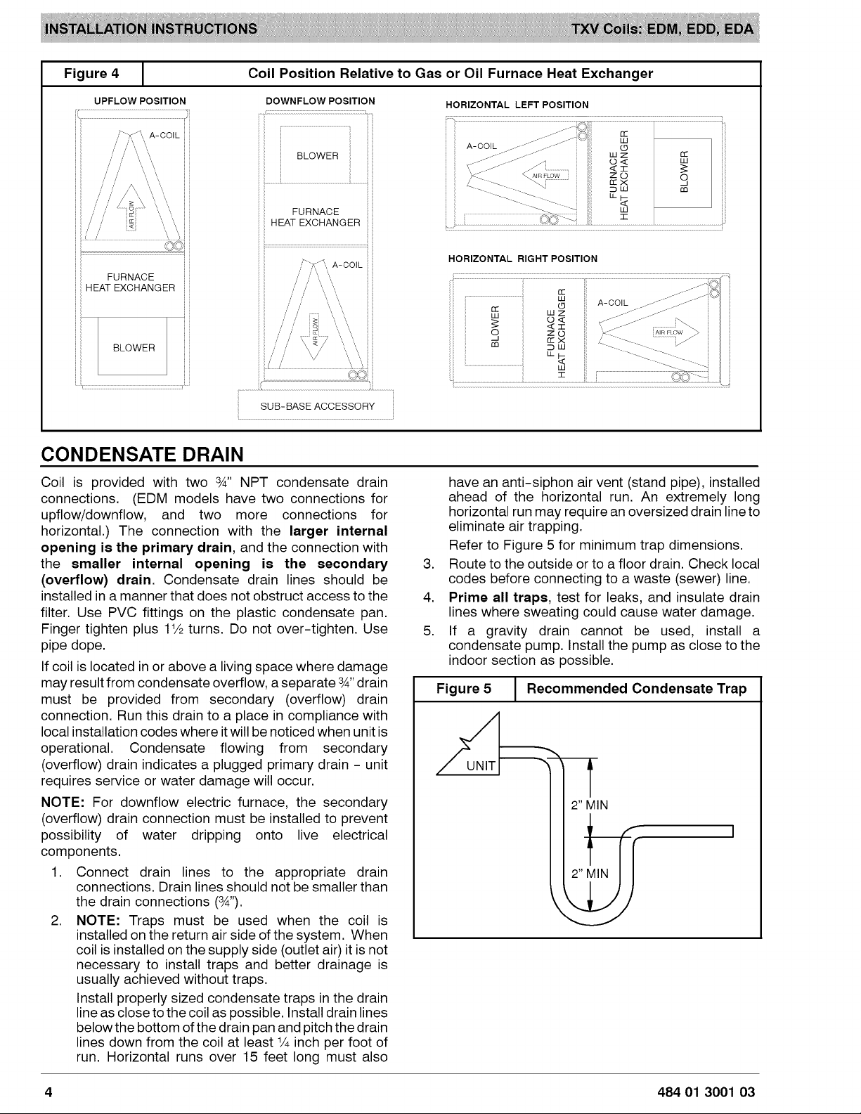
Figure
4
Coil
Position
Relative
to
Gas
or
Oil
Furnace
Heat
Exchanger
UPFLOW
POSITION
DOWNFLOW
POSITIO
HORIZONTAL
LEFT
POSITION
c
Wd
we
a
BLOWER
WZ
he
s6
|
8
ax
9
rc
ae)
a
=
FURNACE
Ww
SUB-BASE
ACCESSORY
HORIZONTAL
RIGHT
POSITION
BLOWER
FURNACE
HEAT
EXCHANGER
CONDENSATE
DRAIN
Coil
is
provided
with
two
%”
NPT
condensate
drain
connections.
(EDM
models
have
two
connections
for
upflow/downflow,
and
two
more
connections
for
horizontal.)
The
connection
with
the
larger
internal
opening
is
the
primary
drain,
and
the
connection
with
the
smaller
internal
opening
is
the
secondary
(overflow)
drain.
Condensate
drain
lines
should
be
installed
in
a
manner
that
does
not
obstruct
access
to
the
filter.
Use
PVC
fittings
on
the plastic
condensate
pan.
Finger
tighten
plus
114
turns.
Do
not
over-tighten.
Use
pipe
dope.
If
coil
is
located
in
or
above
a
living
space
where
damage
may
result
from
condensate
overflow,
a
separate
4” drain
must
be
provided
from
secondary
(overflow)
drain
connection.
Run
this
drain
to
a
place
in
compliance
with
local
installation
codes
where
it
will
be
noticed
when
unitis
operational.
Condensate
flowing
from
secondary
(overflow)
drain
indicates
a
plugged
primary
drain
-
unit
requires
service
or
water
damage
will
occur.
NOTE:
For
downflow
electric
furnace,
the
secondary
(overflow)
drain
connection
must
be
installed
to
prevent
possibility
of
water
dripping
onto
live
electrical
components.
1.
Connect
drain
lines
to
the
appropriate
drain
connections.
Drain
lines
should
not
be
smaller
than
the
drain
connections
(&’).
2.
NOTE:
Traps
must
be
used
when
the
coil
is
installed
on
the
return
air
side
of
the
system.
When
coil
is
installed
on
the
supply
side
(outlet
air)
it
is
not
necessary
to
install
traps
and
better
drainage
is
usually
achieved
without
traps.
Install
properly
sized
condensate
traps
in
the
drain
line
as
close
to
the
coil
as
possible.
Install
drain
lines
below
the
bottom
of
the
drain
pan and
pitch
the
drain
lines
down
from
the
coil
at
least
%
inch
per
foot
of
run.
Horizontal
runs
over
15
feet
long
must
also
have
an
anti-siphon
air
vent
(stand
pipe),
installed
ahead
of
the
horizontal
run.
An
extremely
long
horizontal
run
may
require
an
oversized
drain
line
to
eliminate
air
trapping.
Refer
to
Figure
5
for
minimum
trap
dimensions.
Route
to
the
outside
or to
a
floor
drain.
Check
local
codes
before
connecting
to
a
waste
(sewer)
line.
Prime
all
traps,
test
for
leaks,
and
insulate
drain
lines
where
sweating
could
cause
water
damage.
If
a
gravity
drain
cannot
be
used,
install
a
condensate
pump.
Install
the
pump
as
close
to
the
indoor
section
as
possible.
Figure
5
Recommended
Condensate
Trap
UNIT
2”
MIN
2”
MIN
484
01
3001
03
Loading ...
Loading ...
Loading ...