Loading ...
Loading ...
Loading ...
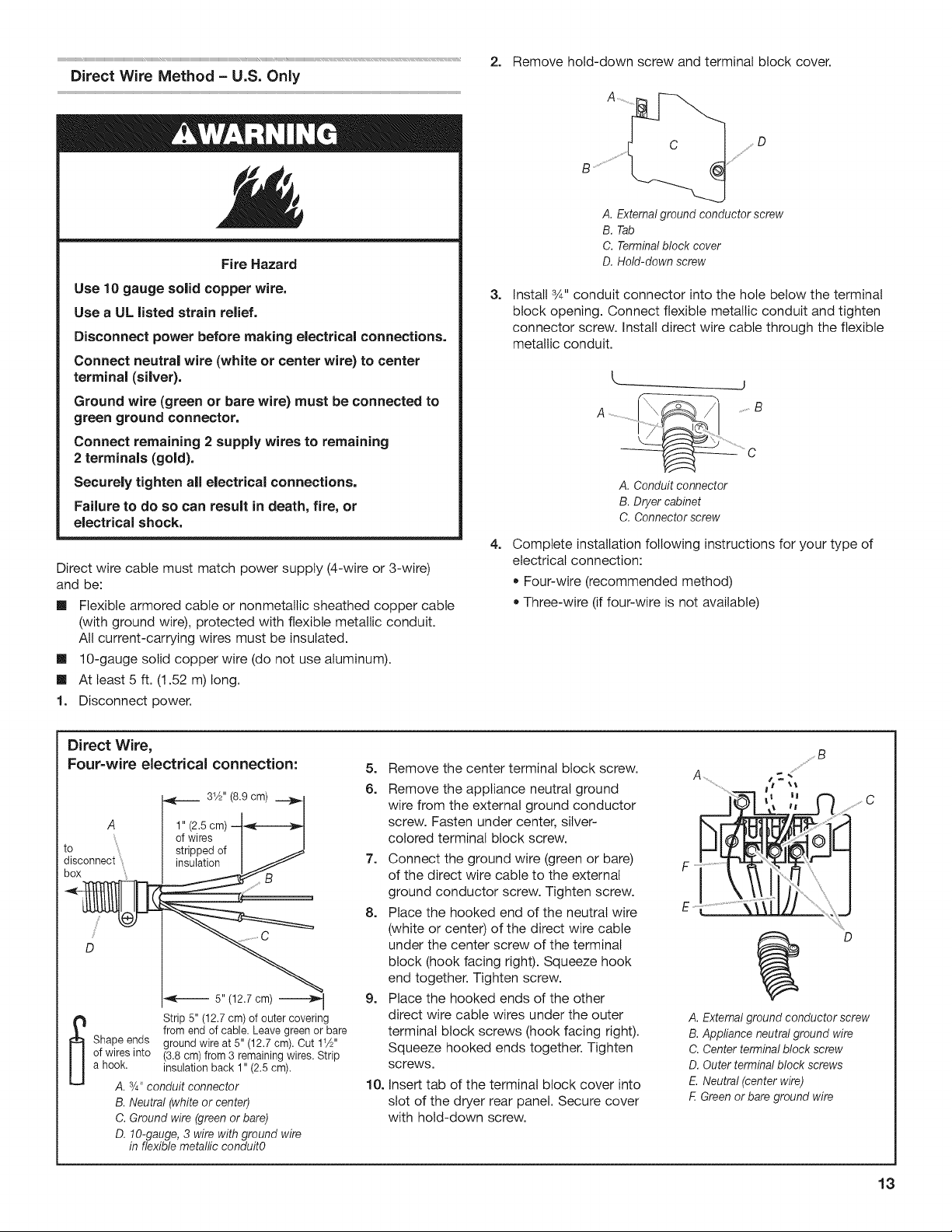
Direct Wire Method - U.S. Only
Fire Hazard
Use 10 gauge solid copper wire.
Use a UL listed strain relief.
Disconnect power before making electrical connections.
Connect neutral wire (white or center wire) to center
terminal (si{ver).
Ground wire (green or bare wire) must be connected to
green ground connector.
Connect remaining 2 supply wires to remaining
2terminals (gold).
Securely tighten all electrica{ connections.
Failure to do so can result in death, fire, or
electrical shock.
Direct wire cable must match power supply (4-wire or 3-wire)
and be:
[] Flexible armored cable or nonmetallic sheathed copper cable
(with ground wire), protected with flexible metallic conduit.
All current-carrying wires must be insulated.
[] 10-gauge solid copper wire (do not use aluminum).
[] At least 5 ft. (1.52 m) long.
1. Disconnect power.
2. Remove hold-down screw and terminal block cover.
D
/
........,s
3=
4=
A. External ground conductor screw
B. Tab
C. Terminalblock cover
D. Hold-down screw
Install ,_A"conduit connector into the hole below the terminal
block opening. Connect flexible metallic conduit and tighten
connector screw. Install direct wire cable through the flexible
metallic conduit.
j
B
A. Conduitconnector
B. Dryercabinet
C. Connectorscrew
Complete installation following instructions for your type of
electrical connection:
• Four-wire (recommended method)
Three-wire (if four-wire is not available)
Direct Wire,
Four=wire e{ectrical connection:
to { °_r_e_jof/_
_ 5" (12.7cm) _
Strip 5" (12.7 cm) of outercovering
fromendof cable.Leavegreenor bare
Shape ends ground wireat 5" (12.7 cm). Cut11A"
ofwiresinto (3.8 cm) from3 remaining wires. Strip
a hook. insulationback1"(2.5 cm).
A. 3/4"conduitconnector
B. Neutral(whiteor center)
C. Groundwire (greenor bare)
D. lO-gauge,3 wirewith groundwire
in flexiblemetallicconduitO
5. Remove the center terminal block screw.
6. Remove the appliance neutral ground
wire from the external ground conductor
screw. Fasten under center, silver-
colored terminal block screw.
7° Connect the ground wire (green or bare)
of the direct wire cable to the external
ground conductor screw. Tighten screw.
8. Place the hooked end of the neutral wire
(white or center) of the direct wire cable
under the center screw of the terminal
block (hook facing right). Squeeze hook
end together. Tighten screw.
9. Place the hooked ends of the other
direct wire cable wires under the outer
terminal block screws (hook facing right).
Squeeze hooked ends together. Tighten
screws.
10. Insert tab of the terminal block cover into
slot of the dryer rear panel. Secure cover
with hold-down screw.
F
E¸
C
D
A. External ground conductor screw
B. Appliance neutral ground wire
C. Center terminal block screw
D. Outer terminal block screws
E. Neutral (center wire)
F.Green or bare ground wire
13
Loading ...
Loading ...
Loading ...