Loading ...
Loading ...
Loading ...
English
7
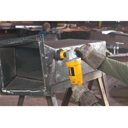
Fitting Guard
CAUTION: Do not operate grinder with a loose guard
or the guard latch in the openposition.
1. Place the angle grinder on a table, spindleup.
2. Press the guarddown.
3. Position the guard between your body and the
workpiece.
4. Tighten the screw holding the cinch collar firmly around
the neck of thespindle.
Fig. D
Removing Guard
1. Loosen the screw holding the cinch collar around the
neck of thespindle.
2. Lift up on theguard.
CAUTION: Do not tighten adjusting screw with guard
latch in open position. Undetectable damage to the
guard or the mounting hub mayresult.
CAUTION: Edge grinding can be performed with
Type 27 wheels designed and specified for this
purpose; 1/4" (6.35 mm) thick wheels are designed for
surface grinding while thinner Type 27 wheels need
to be examined for the manufacturer's label to see
if they can be used for surface grinding or only edge
grinding/cutting. Wheels where surface grinding is not
permitted cannot be used with thisgrinder.
Flanges and Wheels
CAUTION: Turn unit off and unplug the tool before
making any adjustments or removing or installing
attachments oraccessories.
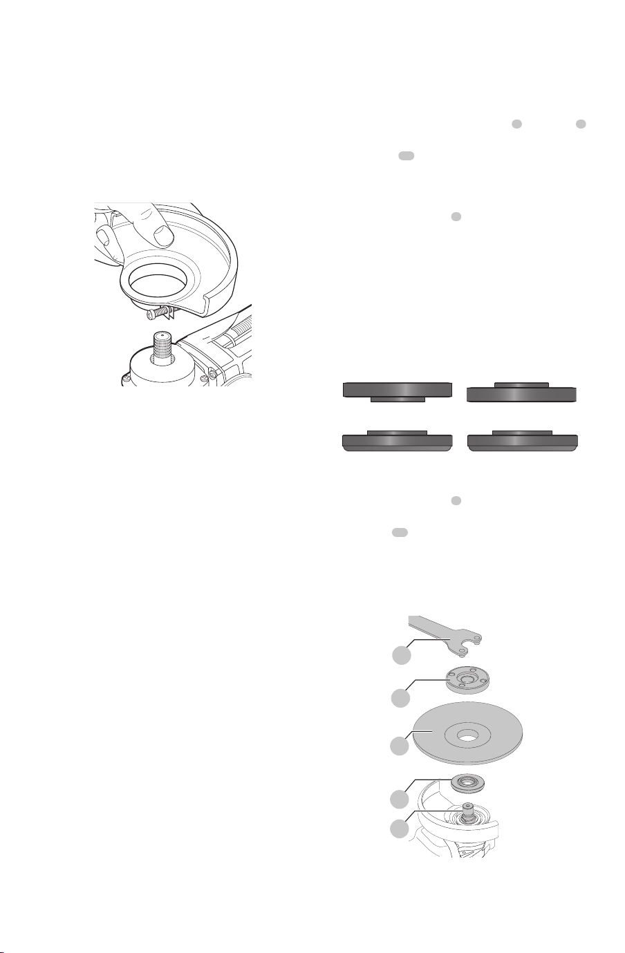
Mounting Non-Hubbed Wheels (Fig. E, F)
WARNING: Failure to properly seat the flanges and/or
wheel could result in serious injury (or damage to the
tool orwheel).
CAUTION: Included flanges must be used with
depressed center Type 27/42 grinding wheels and
Type1/41 cutting wheels. See the Accessories Chart
for moreinformation.
WARNING: A closed, two-sided cutting wheel guard
is required when using abrasive cutting wheels or
diamond coated cutting wheels.
WARNING: Use of a damaged flange or guard or fail-
ure to use proper flange and guard can re sult in injury
due to wheel breakage and wheel contact. See the
Accessories Chart for moreinformation.
1. Place the tool on a table, guardup.
2. Install the unthreaded backing flange
3
, on spindle
1
with the raised center (pilot) facing the wheel.
3. Place wheel
13
against the backing flange,
centering the wheel on the raised center (pilot) of the
backingflange.
4. While depressing the spindle lock button thread the
threaded locking flange
4
on spindle.
nOTE: If the wheel you are installing is more than 1/8"
(3.17mm) thick, place the threaded locking flange on
the spindle so that the raised section (pilot) fits into the
center of the wheel. If the wheel you are installing is
1/8" (3.17mm) thick or less, place the threaded locking
flange on the spindle so that the raised section (pilot) is
not against thewheel.
Fig. E
Over 1/8" (3.17mm)
wheels
Backing Flange
Locking flange
1/8" Or less (3.17mm)
wheels
Backing Flange
Locking flange
5. While depressing the spindle lock button, tighten the
threaded locking flange
4
:
a. Tighten the threaded locking flange using a
wrench
14
.
b. Tighten a keyless locking flange by hand. (Only use a
keyless locking flange if it is in perfect condition.)
6. To remove the wheel, depress the spindle lock button
and loosen the threaded lockingflange.
Fig. F
1
3
13
4
14
Loading ...
Loading ...
Loading ...