1
Serial Number
Purchase Date
Questions, problems, missing parts? Before returning to your retailer, call our customer
service department at 888-251-1003, 8 a. m. – 8 p.m., EST, Monday – Sunday. You could
also contact us at [email protected] or visit www.lowespartsplus.com.
AS21295
ATTACH YOUR RRECEIPT HERE
HARBOR BREEZE and logo design are
trademarks or registered trademarks of
LF, LLC. All rights reserved.
Español p. 20
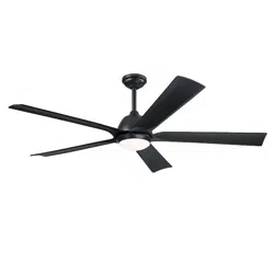
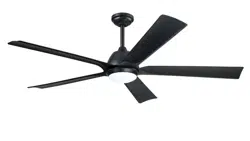
CARTERSVILLE
CEILING FAN
ITEM # 4136495
MODEL #HTD21017-BB

2
TABLE OF CONTENTS
Package Contents...............................................................................................................
Hardware Contents.............................................................................................................
Safety Information...............................................................................................................
Preparation .........................................................................................................................
Initial Installation Instructions ....................................................................................................
Standard/Angle-Mounting Instructions.................................................................................
Wiring Instructions ..............................................................................................................
Final Installation Instructions..................................................................................................
Operating Instruction ..........................................................................................................
Care and Maintenance .......................................................................................................
Troubleshooting...................................................................................................................
Limited Lifetime Warranty....................................................................................................
Replacement Part List .........................................................................................................
3
4
4
5
6
7
9
10
13
15
16
17
FCC Warning.......................................................................................................................
18
19
3
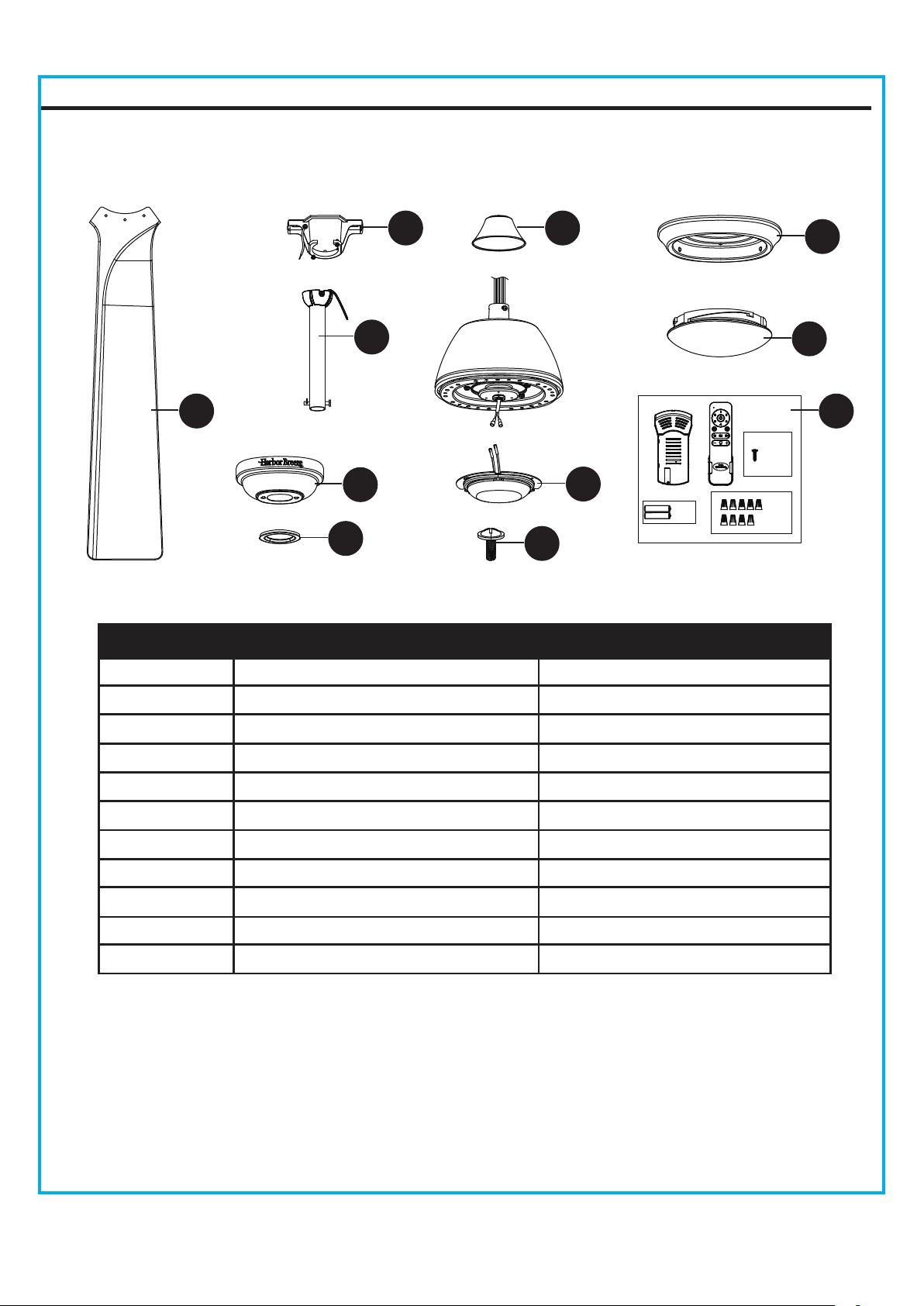
PACKAGE CONTENTS
PART DESCRIPTION QUANTITY PART DESCRIPTION QUANTITY
1
1
C
A
B
Canopy
Mounting Bracket
Downrod Assembly
1
1
D
E
Canopy Cover
Coupling Cover
1
2
1
1
F Motor Assembly 1
2
G Blade 5
H Switch Housing
1
3
I Light Kit 1
J Shade 1
K Remote Unit 1
O
P
M
1
Clevis Pin [Preassembled on
Downrod Assembly (B)]
Hairpin Clip [Preassembled on
Downrod Assembly (B)]
Coupling Screw
[Preassembled on Coupling (O)]
Coupling
[Preassembled on Motor Assembly (F)]
Mounting Bracket Screw
[Preassembled on Mounting Bracket (A)]
Mounting Screw
[Preassembled on Motor Assembly (F)]
L
N
Q
3
Switch Housing Screw
[(Preassembled on Switch Housing (H)]
R
G
A
P
E
H
J
K
I
N
Q
R
O
F
C
D
B
L
M
TM
x 9
x 2
++
--
x 2
4
HARDWARE CONTENTS (not shown actual size)
SAFETY INFORMATION
AA
READ AND SAVE THESE INSTRUCTIONS
Please read and understand this entire manual before attempting to assemble, operate or install the product.
. All electrical connections must comply with local codes, ordinances or the National Electric Code (NEC).
Contact your municipal building department to inquire about your local codes, permits and/or inspections.
. Turn off electricity at main fuse box (or circuit breaker box) before beginning installation by removing fuse
or by switching off circuit breaker.
. Do not connect this fixture to an electrical system that does not provide a means for equipment grounding.
Never use a fixture in a two-wire system that is not grounded.
. If you are not sure your lighting system has a grounding means, do not attempt to install this fixture.
Contact a qualified, licensed electrician for information regarding proper grounding methods as required by
the local electrical code in your area.
. Make sure the installation site you choose allows a minimum clearance of 7 ft. from the blades to the floor
and at least 30 in. from the ends of the blades to any obstruction.
. If a dimmer control switch is used with this fixture, obtain professional advice to determine the correct type
and electrical rating required.
. The lighting fixture must be positioned so there is at least 1.64 ft. between the bulb and any illuminated
surface.
. For supply connections, if the conductor of a fan is identified as a grounded conductor, then it should be
connected to a grounded conductor power supply. If the conductor of a fan is identified as an ungrounded
conductor, then it should be connected to an ungrounded conductor power supply. If the conductor of a fan
is identified for equipment grounding, then it should be connected to an equipment-grounding conductor.
. Installing a fixture into an electrical system without a proper grounding means could allow metal parts of the
fixture to carry electrical currents. If any of the fixture wires, wire connections or splices are broken, cut or
loose during the mounting or normal operation of the fixture, under such condition, anyone coming in contact
with the fixture is subject to electrical shock, which could cause serious injury or death.
. Connection of the bare or green fixture ground wire to the black or white house wires may allow metal parts
of the fixture to carry electrical currents. Under this condition anyone coming in contact with the fixture will
receive electrical shock, which could cause serious injury or death.
. Be careful not to damage or cut the wire insulation (covering) during fixture installation. Do not permit wires
to have contact with any surface having a sharp edge. Doing so may damage or cut the wire insulation,
which could cause serious injury or death from electric shock.
DANGER
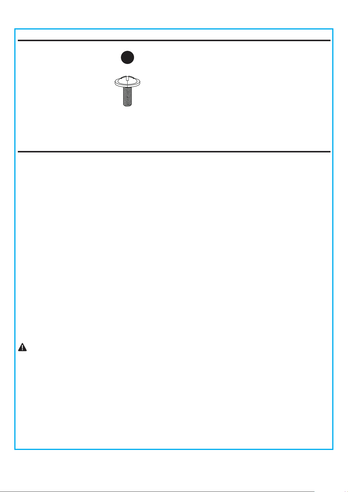
Qty: 15 + 1 extra
Blade Screw
5
WARNING
CAUTION
PREPARATION
Risk of fire. Most dwellings built before 1985 have supply wire rated for 140°F. Consult a qualified
electrician before installation.
To reduce the risk of fire or electric shock, do not use this fan with any solid state fan speed device
or variable speed control.
To reduce the risk of personal injury, do not bend the blade brackets when installing the brackets,
balancing or cleaning the fan.
Do not insert foreign objects in between rotating fan blades.
Do not install or use the fan if any part is damaged or missing
To reduce the risk of fire, electric shock or personal injury, mount to metal outlet box marked
'ACCEPTABLE FOR FAN SUPPORT OF 35 LBS OR LESS' and use mounting screws provided
with the outlet box and/or support directly from building structure. Most outlet boxes commonly
used for the support of luminaries are not acceptable for fan support and may need to be replaced.
Consult a qualified electrician if in doubt.
Before servicing or cleaning the unit, switch power off at the service panel and lock the service
disconnecting means to prevent power from being switched on accidentally. When the service
disconnecting means cannot be locked, securely fasten a prominent warning device, such as a tag,
to the service panel.
Do not use lamp having a wattage greater than the maximum value stated on the fixture. Using a
higher wattage lamp than specified will increase fixture temperature and increase risk of fire.
Before beginning assembly of product, make sure all parts are present. Compare parts with package
contents list and hardware contents list. If any part is missing or damaged, do not attempt to assemble
the product.
Estimated Assembly Time: 45 minutes
Tools Required for Assembly (not included): Phillips Screwdriver, Step Ladder, Tape, Pliers and Wire
Cutters.
6
INITIAL INSTALLATION INSTRUCTIONS
DANGER:
Failure to disconnect power supply prior to
installation may result in serious injury or death.
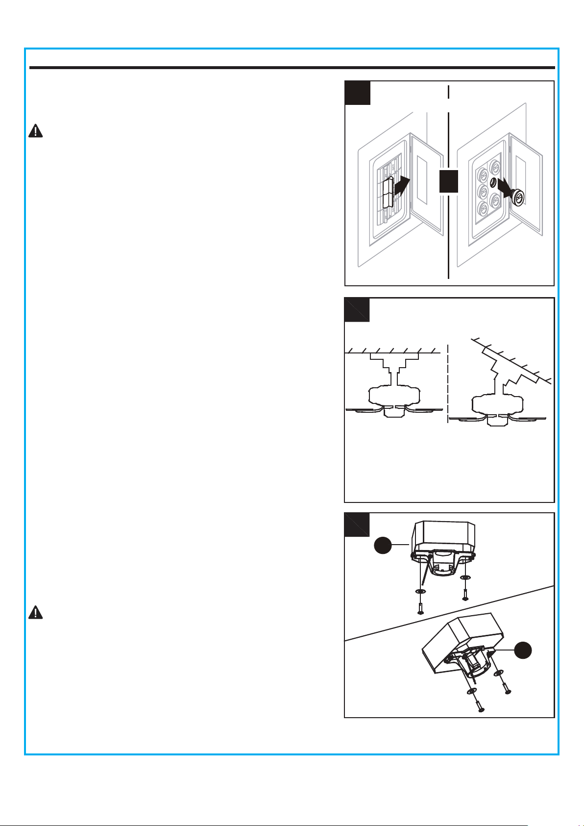
A. Standard Mounting:
B. Angle Mounting:
1. Turn off circuit breakers and wall switch to the fan supply
line leads.
2. Choose the desired mounting method:
Standard mounting is best suited for ceilings 8 feet or
higher. For taller ceilings you may want to use a longer
downrod (not included).
Angle-style mounting is best suited for angled or vaulted
ceilings. A longer downrod is sometimes necessary to
ensure proper blade clearance. If using the angle mount,
make sure the ceiling angle is not steeper than 20°.
3.
Check existing outlet box (not included) to ensure it is
securely fastened to at least two points in a structural
ceiling member and can support the full weight of the fan.
Once verified, install mounting bracket (A) to the outlet
box using the screws and washers provided with the
outlet box.
DANGER: A loose outlet box can cause the fan to
wobble and increase the fan's potential to fall, which
could result in serious injury or death.
Note: If using the angle mount, make sure open end of
mounting bracket (A) points toward the ceiling.
For ALL mounting options, there must be at least 30 inches
from the blade tip to nearest wall. Also, ensure there is 7
feet from the bottom edge of the blade to the floor.
A
B
2
3
Standard
Mounting
A
Angle
Mounting
A
or
T
Turn Off Power Source
1
7
INITIAL INSTALLATION INSTRUCTIONS
4. Loosen the two coupling screws (N) preassembled in
the coupling (O), but do not remove them. Remove the
hairpin clip (M) and clevis pin (L) from the downrod
assembly (B). Retain for later use.
Note: Make sure to keep loose hardware separate to
avoid confusion during installation.
STANDARD/ANGLE-MOUNTING INSTRUCTIONS
1. Place downrod assembly (B) through canopy (C),
canopy cover (D) and coupling cover (E).
Feed power wires from motor assembly (F) through
downrod assembly (B), then insert downrod assembly (B)
into the coupling (O) on motor assembly (F).
C
D
E
B
O
O
1
2. Align the hole on downrod assembly (B) to hole on the
coupling (O), then re-install clevis pin (L). Re-attach
hairpin clip (M) into clevis pin (L) until it snaps into
place, then tighten the two previously loosened
coupling screws (N).
2
O
N
M
B
L
M
4
L
N
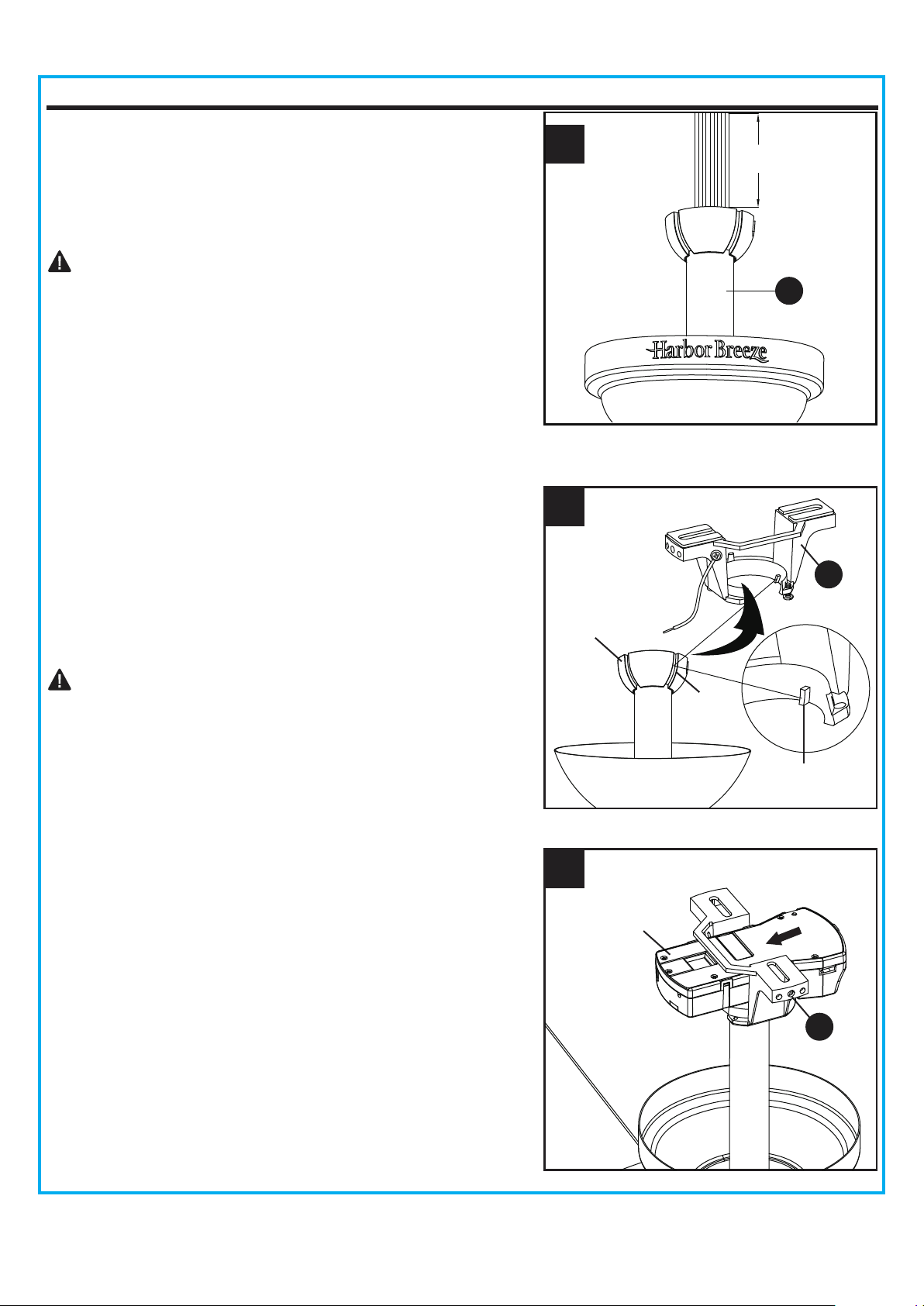
8
CAUTION: Ensure all screws are tight before moving
to the next step.
STANDARD/ANGLE-MOUNTING INSTRUCTIONS
3. Cut off excess fixture wires, leaving approximately 6 to
9 inches above the top of the downrod assembly (B).
Strip 1/2 inch of insulation from the end of each fixture
wire.
4. Carefully lift the assembly and rest the hanger ball of
downrod assembly (B) on the mounting bracket (A)
attached to the outlet box. Be sure the groove in the
hanger ball is lined up with the tab on the mounting
bracket (A). This will allow for hands-free wiring.
Proceed to WIRING on Page 9.
DANGER: Be careful when aligning the tab to the
groove! If not fully engaged, there is a possibility of the
fan falling, which may result in serious injury or death.
3
A
B
A
4
5. Slide the receiver into the mounting bracket (A) before
wiring as shown.
5
Hanger Ball
Receiver
Groove
Tab
6 to 9 in
1
9
Hardware Used
Wire Connector x 8
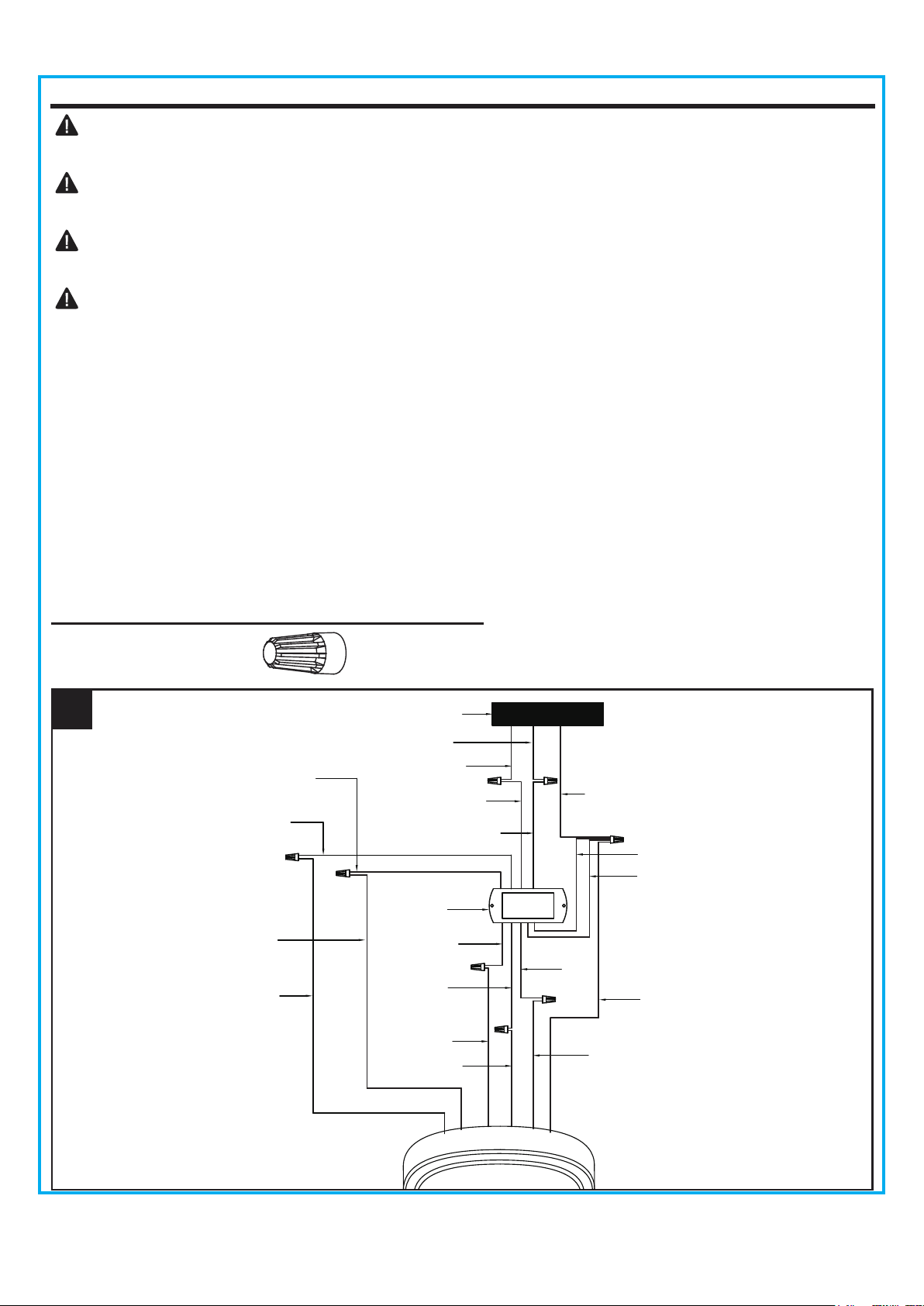
WIRING INSTRUCTIONS
1. Follow steps below to wiring your fan:
● Connect WHITE wire from the fan to WHITE wire marked FOR LIGHT from the receiver.
● Connect BLUE wire from the fan to BLUE wire marked FOR LIGHT from the receiver.
● Connect YELLOW wire from the fan to YELLOW wire from the receiver.
● Connect GRAY wire from the fan to GRAY wire from the receiver.
● Connect RED wire from the fan to RED wire from the receiver.
● Connect BLACK wire marked AC IN L from the receiver to the BLACK supply wire.
● Connect WHITE wire marked AC IN N from the receiver to WHITE supply wire.
● Connect GROUND (GREEN) wires from mounting bracket, downrod ball and receiver, to GROUND
(GREEN or BARE COPPER) from house.
WARNING: To avoid possible electrical shock, be sure electricity is turned off at the main fuse
box before hanging.
WARNING: If you are not sure if the outlet box is grounded, contact a licensed electrician for
advice, as it must be grounded for safe operation.
WARNING: If house wires are different colors than referred to in the following steps, stop
immediately. A professional electrician is recommended to determine proper wiring.
WARNING: If you feel that you do not have enough electrical wiring knowledge or experience,
have your fan installed by a licensed electrician.
Outlet box
Black
Ground wire
White (AC IN N)
Black(AC IN L)
White
Yellow
Gray
Gray
Yellow
Red
Red
Ground wire
Receiver
Ground wire
Ground wire
White (FOR LIGHT)
White (FOR LIGHT)
Blue (FOR LIGHT)
Blue (FOR LIGHT)
WIRING INSTRUCTIONS
2. Wrap electrical tape (not included) around each wire
connector and make sure no bare wire or wire strands
are visible after making connections. Then, turn wires
upward and carefully push them into the outlet box;
make sure the WHITE and GREEN connections are on
one side and the BLACK connections are on the other
side.
2
BLACK
WHITE
GREEN
Outlet Box
10
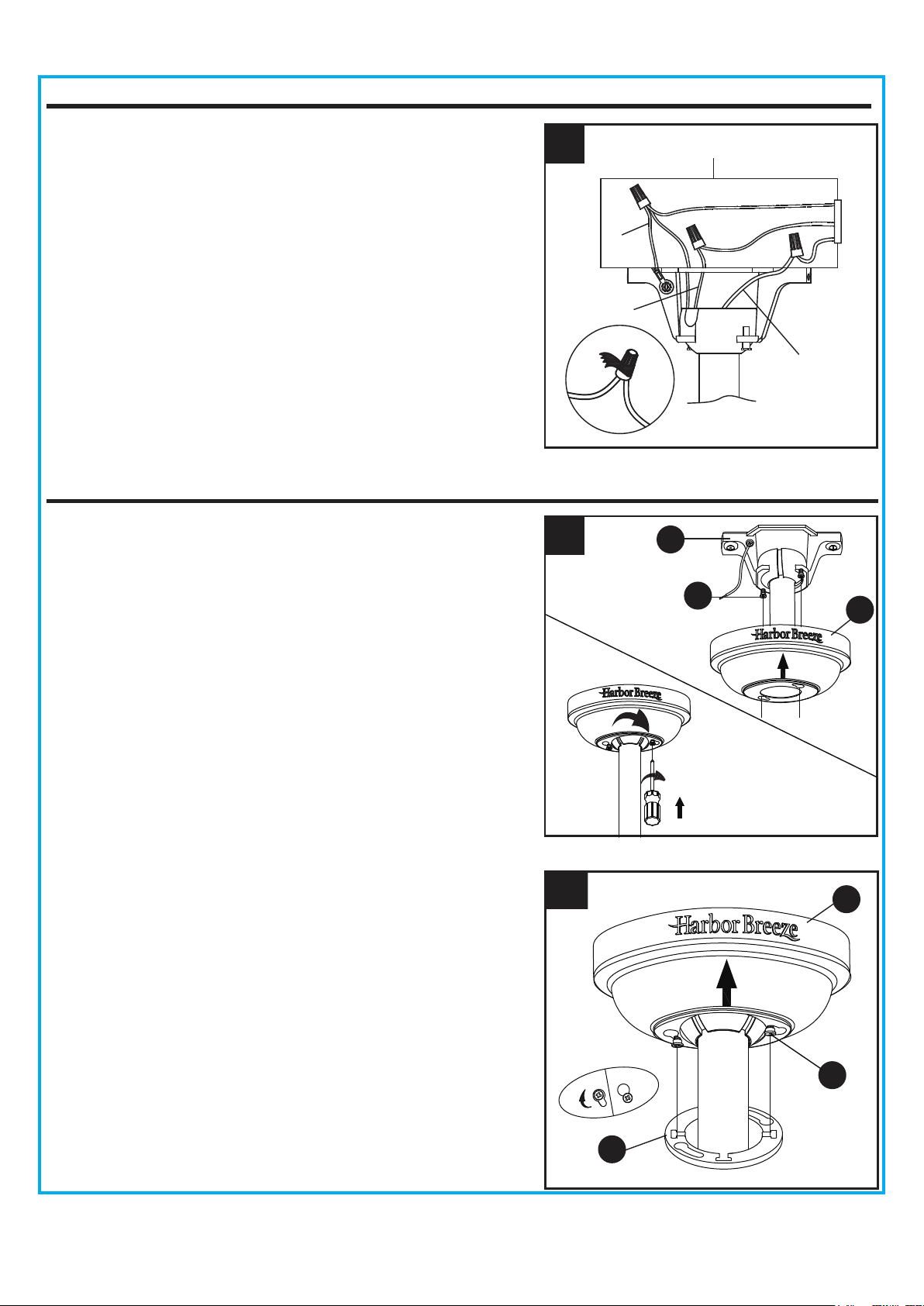
FINAL INSTALLATION INSTRUCTIONS
1. Loosen (but do not remove) the two preassembled
mounting bracket screws (P) on mounting bracket (A)
that align with the slotted holes on canopy (C). Lift
canopy (C) up so slotted holes engage loosened screw
heads on mounting bracket (A), then twist canopy (C)
clockwise, then tighten all screws securely.
2. Raise canopy cover (D) over the mounting bracket
screws (P) visible in canopy (C). Rotate canopy
cover (D) clockwise until it locks into place. You may
need to adjust the mounting bracket screws (P) until the
canopy (C) and canopy cover (D) have a snug fit.
2
1
C
D
P
A
P
C
FINAL INSTALLATION INSTRUCTIONS
11
FINAL INSTALLATION INSTRUCTIONS
5. Insert the wires with 2 single pin connectors from the
motor assembly through the center hole in the switch
housing (H). Attach the switch housing (H) to the
mounting plate on the motor assembly by placing the
keyhole slots from the switch housing (H) onto the two
protruding mounting screws (Q) heads. Adjust the switch
housing (H) until the screw heads are aligned with the
keyholes, then re-install the mounting screw (Q)
previously removed on step 4. Tighten all mounting
screws (Q) securely.
4
4. Remove one of the mounting screws (Q) on mounting
plate of motor assembly (F), then loosen the other two.
5
F
Q
H
Q
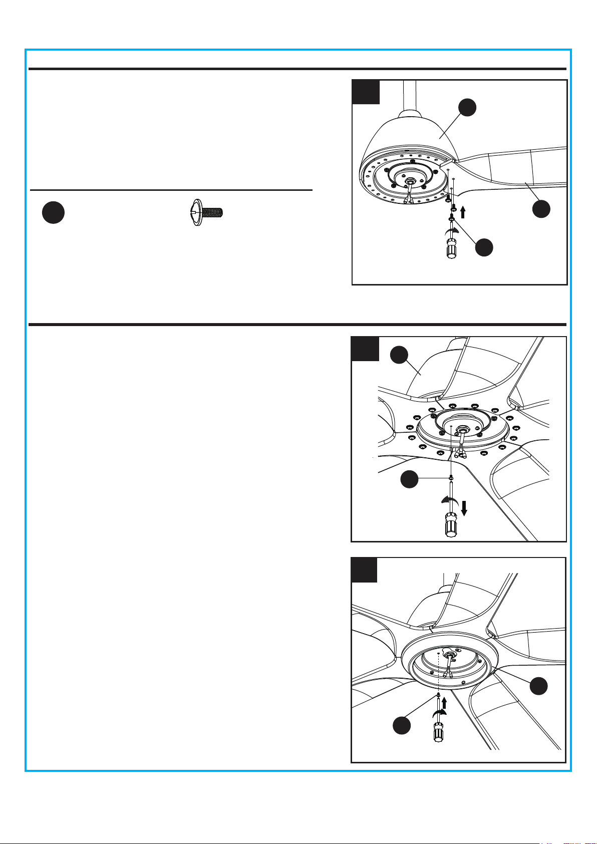
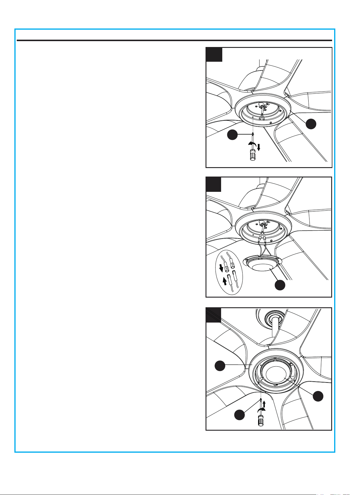
3. Attach blade (G) to the motor assembly (F) with blade
screws (AA) provided.Repeat for the other blades.
Hardware Used
Blade Screw x 15
AA
F
G
3
AA
I
H
R
12
FINAL INSTALLATION INSTRUCTIONS
8. Attach the light kit (I) to switch housing (H) using the
two key slots in the light kit (I). Replace the screw
previously removed on step 6. Tighten all switch
housing screws (R) securely.
6. Remove one of three switch housing screws (R ) on
the switch housing (H) and keep for later use, then
loosen the other two.
6
7. Connect the 2 single pin connectors from the light kit (I)
to the 2 single pin connectors from the motor
assembly. Connect the black wire to black wire, and
white wire to white wire.
7
8
I
H
R
13
FINAL INSTALLATION INSTRUCTIONS
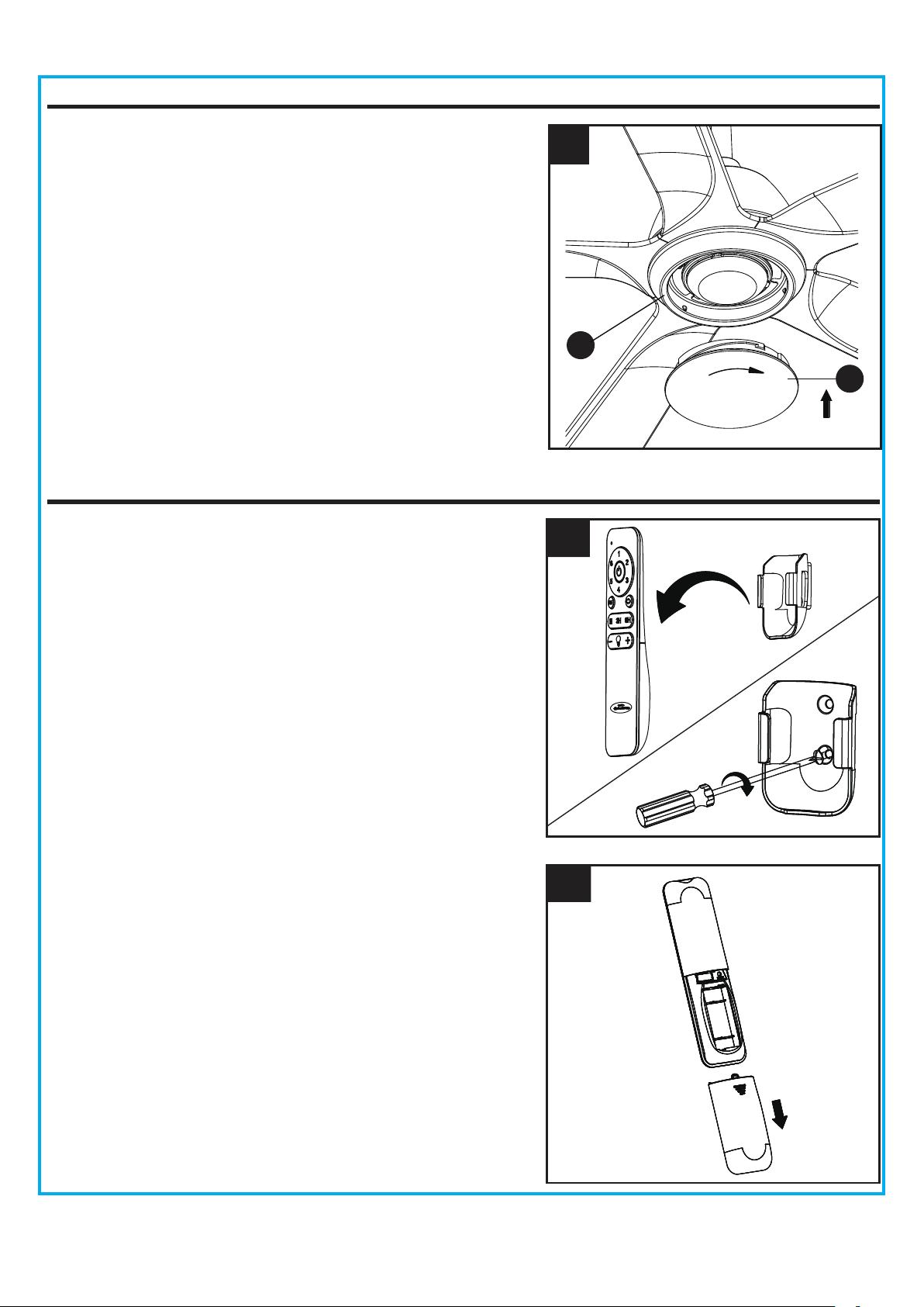
OPERATIING INSTRUCTIONS
2. Open the battery cover.
2
1. Slide the transmitter out of the transmitter holder. Select
a location to install your transmitter holder. Attach the
transmitter holder with screws provided.
1
9. Secure the shade (J) to switch housing (H) by twisting
in a clockwise direction. Do not over-tighten.
9
J
H
OPERATIING INSTRUCTIONS
14
3
4
3. To make fan operational, install two 1.5V AAA batteries
(included). Replace the battery cover.
NOTE:
This remote control uses two 1.5V AAA batteries.
Replace batteries with the correct size and type of battery.
Clean the battery contacts and area inside the device
prior to installing new batteries. Ensure the batteries are
installed correctly with regard to the polarity ( + and -).
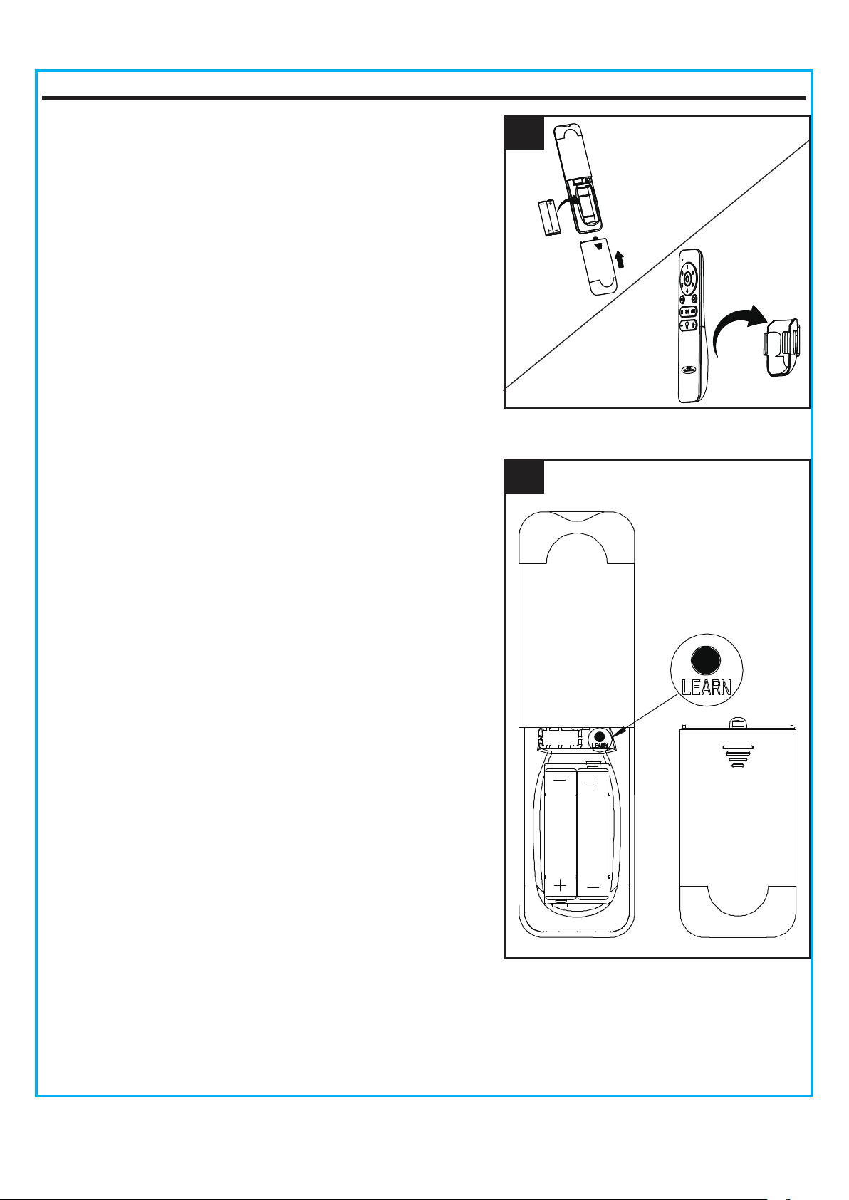
NOTE:
If not used for long periods of time, remove
battery to prevent damage to transmitter. Store the
remote control away from excessive heat and humidity.
4. Each transmitter of this remote control carries a unique
ID code to facilitate communication between paired
devices. The ID code is set by factory and is not user
changeable. However, you will be required to perform
an “ID code learning” process manually under these
circumstances.
•
If you have multiple fans installed within a close
proximity and want to control all fans using a same
remote transmitter.
NOTE:
Each fan requires its own receiver.
•
When your remote control is not responding (make
sure battery is not flat).
•
After you have replaced a faulty transmitter or receiver
with a new one.
Otherwise the remote control will not work. To perform
this process manually, follow steps below:
Press the “ LEARN” button for 5 seconds or more within
30 seconds after restoring power to the fan, the fan will
beep twice and the light will flash twice. This indicate the
code learning process have been completed.
CARE AND MAINTENANCE
Important:
Shut off main power supply before beginning any maintenance. Do not use water or a
damp cloth to clean the ceiling fan.
. At least twice each year, tighten all screws and lower canopy to check mounting plate screws.
. Clean fan housing with only a soft brush or lint-free cloth to avoid scratching the finish. Clean blades
with a lint-free cloth. You may occasionally apply a light coat of furniture polish to wood blades for
added protection.
15
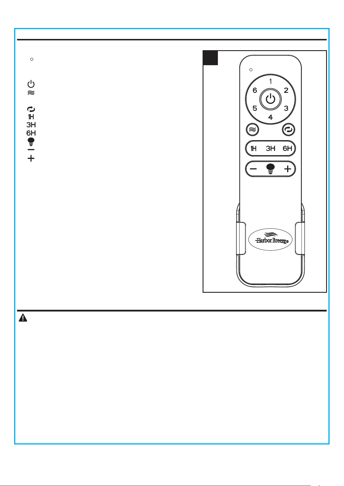
OPERATING INSTRUCTIONS
5. Remote functions:
Indicator light
Buttons (1 to 6) : Fan speed.
: Turns fan off.
: Fan speed will modulate to simulate a natural
breeze.
: Fan turns forward or reverse.
: Fan and light will turn off after 1 hour.
: Fan and light will turn off after 3 hours.
: Fan and light will turn off after 6 hours.
: Turn light ON/OFF.
: Decrease the light output level
: Increase the light output level
NOTE: The fan has a preset memory function, it will
stay at the same speed and brightness as the last time
it was turned off.
5
1. Set screws are loose. 1. Tighten all set screws.
2. Using non-approved speed control. 2. Some fan motors are sensitive to signals from solid-
state varible speed controls. DO NOT USE a solid-
state variable speed control.
3. Normal noise. 3. Allow "break-in" period of 24 hours. Most noises
associated with a new fan will disappear after this
period.
4. Wire connectors inside switch
housing rattling.
4. Check
to make sure wire connectors in switch
housing are not rattling against each other or against
the interior wall of the switch housing.
5. Cracked blade. 5. Replace blades.
6. The distance from canopy to ceiling
is too great.
6. Make sure upper canopy is a short distance from
ceiling. It should not touch the ceiling.
7. Glass is not secure. 7. Secure the glass.
1. Hanger bracket and/or ceiling outlet
box is not securely fastened.
1. Tighten the hanger bracket screws to the outlet box,
and/or secure outlet box.
2. Set screw in downrod assembly is
loose.
2. Tighten the set screw in the downrod assembly.
seated in canopy tabs.
3. Fan hanger ball is not properly 3. Turn power off, support the fan very carefully, and
check that the hanger ball is properly seated.
4. Set screw in motor coupling is loose. 4. Raise motor coupling up and tighten set screws
securely.
5. Blade is loose. 5. Check that all blades are screwed firmly into blade
holders.
Fan sounds noisy
Fan wobbles
TROUBLESHOOTING
PROBABLE CAUSE CORRECTIVE ACTION
PROBLEM
16
6. Blade out of balance. 6. Interchange two adjacent blades; this will redistribute
the weight and possibly result in smoother operation.
7. Fan too close to vaulted ceiling.
7. Lower or move fan. Extension downrods may be
ordered.
8. Transition to different speed. 8. When switching from medium to low speed, you may
notice some fan wobble in the fan. When the fan
stabilizes at low speed, wobble should disappear.
9 . Fan not securely mounted. 9 . Make sure canopy and mounting bracket are
tightened securely to ceiling joist.
1. Power turned off, fuse blown or
circuit
breaker tripped.
1. Turn power on, replace fuse or reset breaker.
1. Wrong wire connection.
1. Refer to Step 7, page 12 to ensure all wire
connections were done correctly.
Fan d
oes not start
2b. Check the plug connection in the switch housing.
2a. Turn power off and loosen canopy; check all
connections according to section WIRING
INSTRUCTIONS on page 9.
2. Loose w
ire connections or wrong
connections.
Light does not work

17
LIMITED LIFETIME WARRANTY
The manufacturer warrants this fan to be free from defects in workmanship and material present at
time of shipment from the factory for life (with limitations) from the date of purchase. This warranty
applies only to the original purchaser. The manufacturer agrees to correct such defect at no charge
or, at our option, replace the ceiling fan with a comparable or superior model.
To obtain warranty service, present a copy of your sales receipt as proof of purchase. All cost of
removal and reinstallation are the expressed responsibility of the purchaser. Any damage to the
ceiling fan by accident, misuse or improper installation, or by affixing accessories not produced by
this warranty, are at the purchaser’s own responsibility. The manufacturer assumes no responsibility
whatsoever for fan installation during the limited lifetime warranty. Any service performed by an
unauthorized person will render the warranty invalid.
Due to varying climatic conditions, this warranty does not cover changes in brass finish, rusting,
pitting, tarnishing, corroding or peeling. Brass finish fans maintain their beauty when protected from
varying weather conditions.
The duration of any implied warranty which can not be disclaimed is limited to the lifetime limited
period as specified in our warranty. The manufacturer shall not be liable for incidental, consequential
or special damages arising at or in connection with product use or performance except as may other
wise be accorded by law. This warranty gives you specific legal rights, and you also have other rights
which vary from state to state. This warranty supersedes all prior warranties.
NOTE: A small amount of “ wobble ” is normal and should not be considered a defect.
Any replacement of defective parts for the ceiling fan must be reported within the first year from
the date of purchase. For the balance of the warranty, call our customer service department at
888-251-1003 for return authorization and shipping instruc tions so that we may repair or replace the
ceiling fan. Any fan or parts returned improperly packaged is the sole responsibility of the purchaser.
There is no further expressed warranty. The manufacturer disclaims any and all implied warranties.

18
FCC WARNING
This device (including remote control and LED module) complies with Part 15 of the FCC Rules.
Operation is subject to the following two conditions:
(1) This device may not cause harmful interference, and (2) this device must accept any interference
received, including interference that may cause undesired operation. Please note that changes or
modifications not expressly approved by the party responsible for compliance could void the user's
authority to operate the equipment.
Note: Both the remote control and LED module have been tested and found to comply with the limits
for Class B digital device, pursuant to part 15 of the FCC Rules. These limits are designed to provide
reasonable protection against harmful interference in a residential installation.
The remote control generates, uses and can radiate radio frequency energy and, if not installed and
used in accordance with the instructions, may cause harmful interference to radio or television
reception, which can be determined by turning the equipment off and on, the user is encouraged to
try to correct the interference by one or more of the following measures:
- Reorient or relocate the receiving antenna.
- Increase the separation between the equipment and the receiver.
- Connect the equipment into an outlet on a circuit different from that to which the receiver is
connected.
Consult the dealer or an experienced radio/TV technician for help.
Blade
Switch Housing
Light Kit
Shade
Remote Unit
19
Printed in China
REPLACEMENT PART LIST
For replacement parts, call our customer service department at 888-251-1003 8 a.m. -8 p.m., EST,
Monday – Sunday. You could also contact us at [email protected] or visit www.lowespartsplus.com.
A Mounting Bracket A102-0460070
A103-0443513
A101-0281513
A108-0013513
A106-0488513
A141-0682002
A188-0421513
A187-0544513
A182-0580001
A137-0699001
B166-1325070
Downrod Assembly
Canopy
Canopy Cover
Coupling Cover
Blade Screw
B
C
D
E
G
H
I
J
K
AA
Part Description Part#
G
A E
H
J
K
I
C
D
AA
B
TM
x 9
x 2
++
--
x 2