MODELS BHFLED80 • BHF80
Page 1
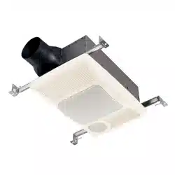
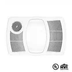
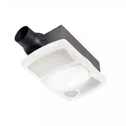
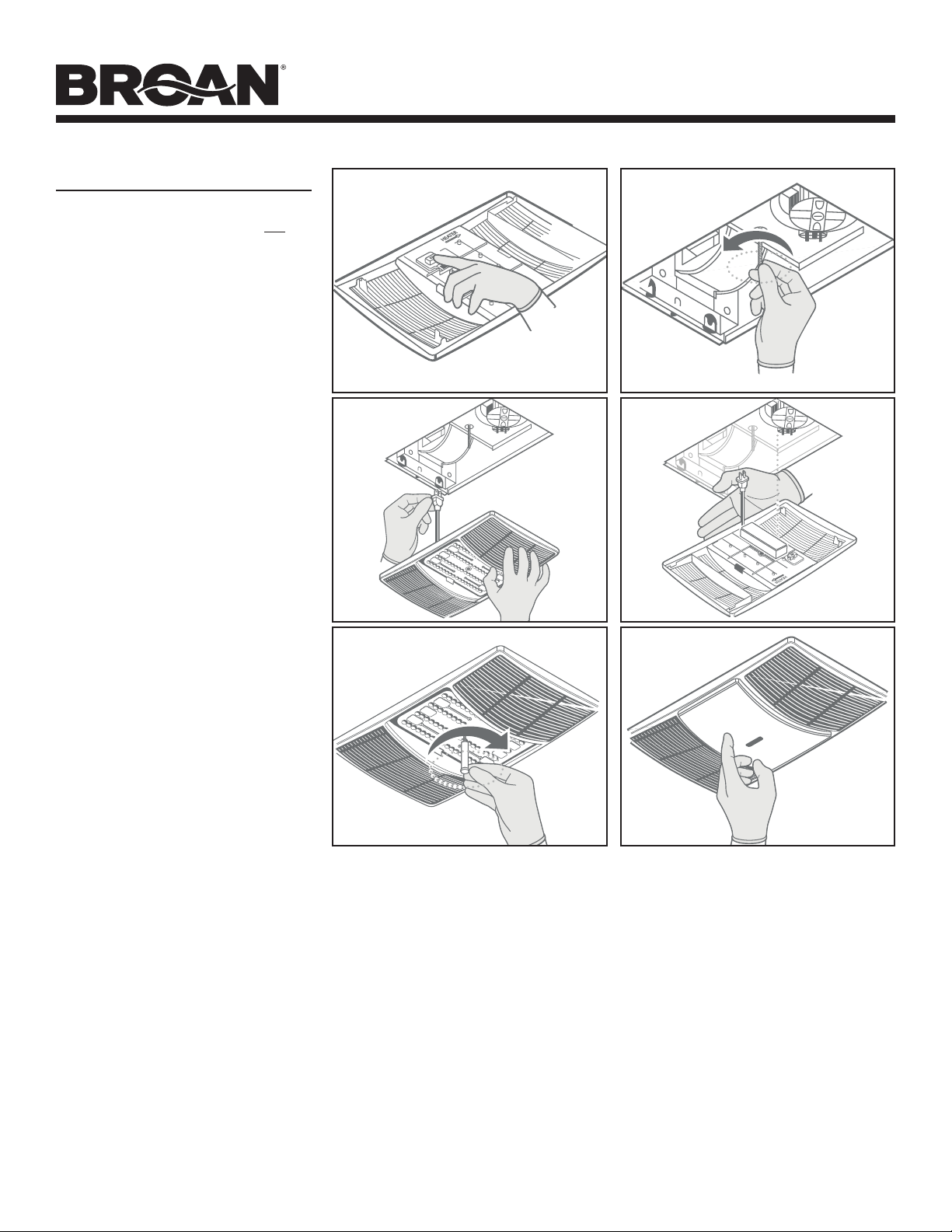
HEATER / FAN / LIGHT
READ AND SAVE THESE INSTRUCTIONS
FIG. 1
FIG. 2
FIG. 3
FIG. 4
FIG. 5
RETAINING
SCREWS
HINGE PIN
IMPORTANT INSTRUCTIONS
READ ALL INSTRUCTIONS BEFORE INSTALLING OR USING THIS HEATER.
To reduce the risk of fire, electric shock, or injury to persons, observe the following:
1. Use this unit only in the manner intended by the manufacturer. If you have questions, contact the
manufacturer at the address or telephone number listed in the warranty.
2. Before servicing or cleaning unit, switch power off at service panel and lock the service disconnecting
means to prevent power from being switched on accidentally. When the service disconnecting means
cannot be locked, securely fasten a prominent warning device, such as a tag, to the service panel.
3. Installation work and electrical wiring must be done by a qualified person(s) in accordance with all
applicable codes and standards, including fire-rated construction codes and standards.
4. When cutting or drilling into wall or ceiling, do not damage electrical wiring and other hidden utilities.
5. This heater is hot when in use. To avoid burns, do not let bare skin touch hot surfaces. Keep
combustible materials, such as furniture, pillows, bedding, papers, clothing, curtains, etc. at least
3 feet (0.9 m) from the front of the heater.
6. Extreme caution is necessary when any heater is used by or near children or invalids and whenever
the heater is left operating and unattended.
7. Do not operate any heater after it malfunctions. Disconnect power at service panel and have heater
inspected by a reputable electrician before reusing.
8. Do not use outdoors.
9. To disconnect heater, turn controls to off, and turn off power to heater circuit at main disconnect
panel (or operate internal disconnect switch, if provided).
10. Do not insert or allow foreign objects to enter any ventilation or exhaust opening, as this may cause
an electric shock or fire, or damage the heater.
11. To prevent a possible fire, do not block air intakes or exhaust in any manner.
12. A heater has hot and arcing or sparking parts inside. Do not use it in areas where gasoline, paint, or
flammable vapors or liquids are used or stored.
13. Use this heater only as described in this manual. Any other use not recommended by the
manufacturer may cause fire, electric shock, or injury to persons.
14. This product must be grounded.
15. Do not install heater in a tub or shower enclosure.
16. This product is designed for ceiling installation only. This product is designed for installation in
ceilings up to a12/12 pitch. Ductwork must point up. DO NOT MOUNT THIS PRODUCT IN A WALL.
17. Install heater at least 6 inches from floor or any adjacent wall.
18. Do not connect heater to dimmer switch or speed control.
19. Provide a separate 20 AMP circuit. Use 12 GA. power cable of type which meets code.
20. For greatest efficiency, install heater so heat is directed toward tub or shower area. Avoid directing
toward walls or windows.
SAVE THESE INSTRUCTIONS
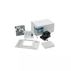
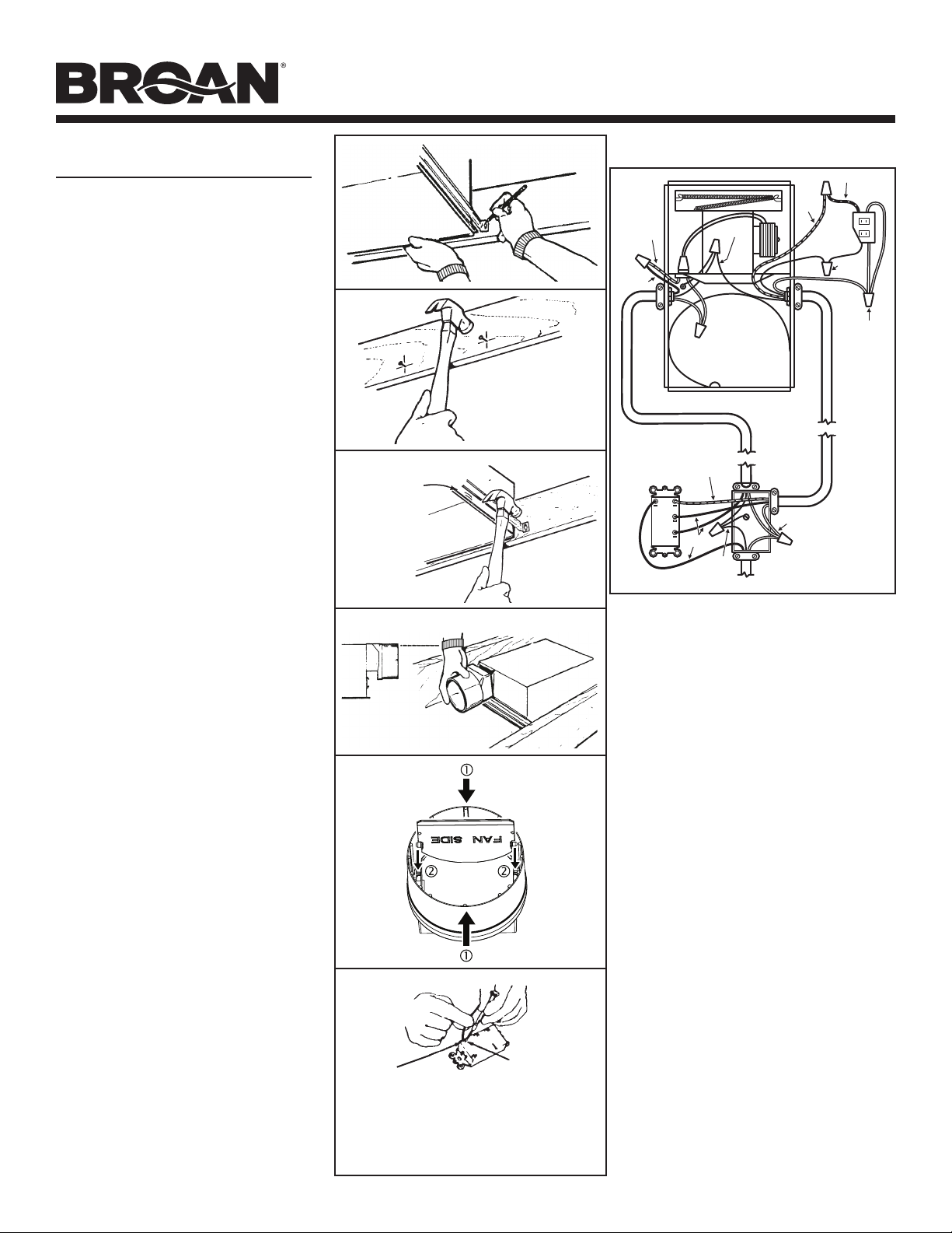
PREPARATION
1. Make sure the heater assembly is unplugged from the RED receptacle.
2. Loosen the two retaining screws on the inside of the heater discharge opening. Place a screwdriver
tip between the outer wall of the discharge opening and the fan housing. Gently pry outward until
the exhaust discharge slips off the support lip on the outer housing. (FIG. 1)
3. Unhook hinge pins and lift heater assembly out of housing. (FIG. 2)
CAUTION: REMOVE THE SHIPPING RING FROM THE HEATER BLOWER INLET BEFORE OPERATING
THE HEATER.
4. Unplug the fan assembly from the BLACK receptacle.
5. Remove the mounting screw and carefully lift the fan assembly out of the housing. (FIG. 3)
6. Refer to the wiring diagram on the next page. Remove appropriate knockout(s) by inserting a
screwdriver blade into slots and bending it back and forth to break tabs. (FIG. 4)
7. Insert the adjustable mounting brackets into the bracket channels on the housing. (FIG. 5)
For Warranty Statement, Service Parts, Technical Support, or to Register your product,
please visit our website www.broan-nutone.com or call 800-558-1711.
KNOCKOUTS
MODELS BHFLED80 • BHF80
Page 2
RED
WHITE
BLACK
120 VAC LINE IN
LIGHT
VENT
HEAT
GROUND
RED
BLACK
GROUND
RED
BLUE
WHITE
BLACK
INSTALLATION
WARNING: To reduce the risk of fire, do not store
or use gasoline or other flammable vapors and
liquids in the vicinity of the heater.
CAUTION: High temperature, risk of fire, keep
electrical cords, drapery, furnishings, and
other combustibles at least 3 feet (0.9 m) from
the front of the heater and away from the side
and rear.
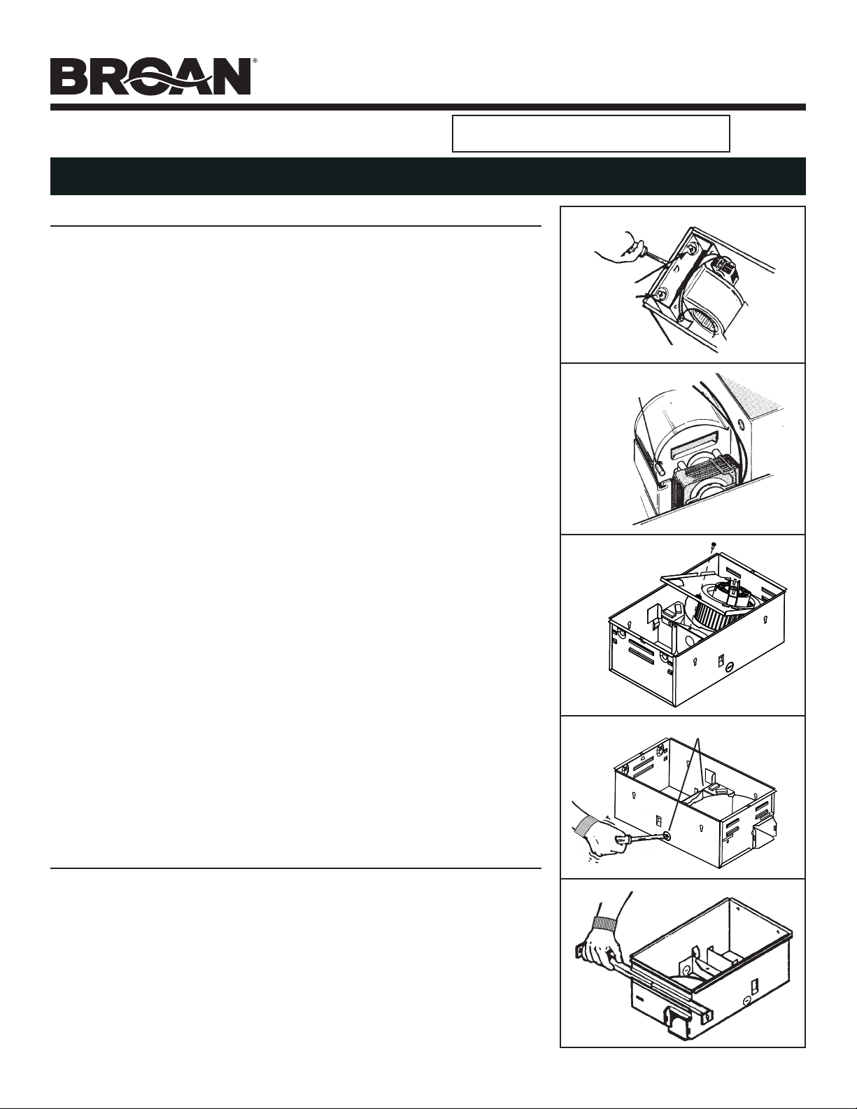
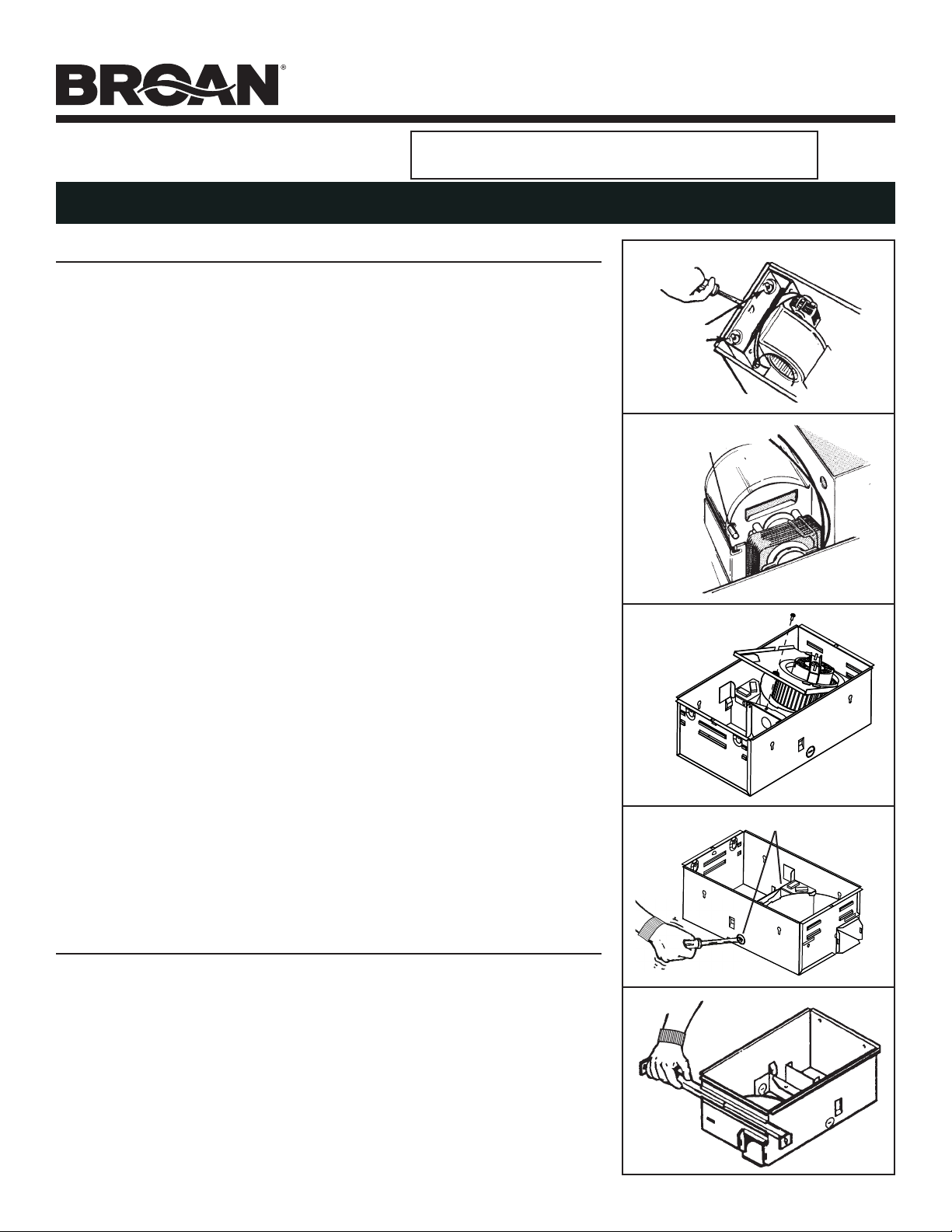
8. For best results, choose a location which allows
fan to be vented outside with the shortest
possible duct run and the fewest number of
elbows.
9. Position unit between joists and extend
mounting brackets. Position brackets such
that the bottom edge of housing will be flush
with finished ceiling. Mark the top of keyhole
slot on all four mounting brackets. (FIG. 6)
10. Remove unit temporarily, and drive nails
partially into joists at all four marked locations.
(FIG. 7)
11. Hang unit from nails and use embossed
measuring guides to check if unit will be flush
with finished ceiling. Drive nails tight. For wide
joist centers: A #8 x 3/8 self-tapping screw can
be used to join extended brackets together and
create a rigid mount. To ensure a noise-free
mount, crimp the bracket channels tightly
around mounting brackets. (FIG. 8)
12. Snap the damper/duct connector onto housing.
Make sure that tabs on the connector lock in
housing slots. (Top of damper/duct connector
will be flush with top of housing.) (FIG. 9)
NOTE: Make sure damper flap is in place inside
of duct connector. If it is not: Squeeze top
and bottom of connector to snap flap back
into place. (FIG. 10)
Installation work and electrical wiring must be
done by a qualied person(s) in accordance
with all applicable codes and standards,
including re-rated construction codes and
standards.
13. Wire unit according to Figure 11.
14. Replace heater assembly removed in STEP 3
and plug it into RED receptacle. Direct wires
away from blower inlet.
15. Replace fan assembly removed in STEP 5 and
plug it into BLACK receptacle.
FIG. 6
FIG. 7
FIG. 8
EMBOSSED
MEASURING
GUIDES
FIG. 9
FLUSH
FIG. 10
FIG. 11
NOTE
WIRE
OPENING
RELEASE SLOT
If the switch* has not been wired properly and wires need
to be moved:
1. Each wire opening has a release slot.
2. Push a small nail or screwdriver into release slot while gently
removing wire.
3. DO NOT pull any wire out of the switch without using the
release slot. The switch may be damaged.
*switch not included

MODELS BHFLED80 • BHF80
Page 3
INSTALLATION (CONT’D)
CAUTION: To avoid the possibility of overheating
and/or re, the grille must be installed as shown.
16. Before installing fan cover, plug in the light of
your new cover (in any outlet) and select LED
color temperature using CCT switch. (FIG. 12)
17. Extend mounting screw as much as possible.
(FIG. 13)
18. Plug in light plug (plug may differ from that
pictured). (FIG. 14)
19. Orientate LED driver on light cover toward fan
side. (FIG. 15)
20. Secure cover by threading mounting post over
mounting screw. Hand-tighten mounting post
until cover is secure against ceiling surface.
(FIG. 16)
21. Snap in lens. (FIG. 17)
FIG. 12
FIG. 13
FIG. 14
FIG. 15
FIG. 16 FIG. 17
NOTE: BHF80 fan cover (grille) will be slightly
different from what shown in pictures.

MODELS BHFLED80 • BHF80
Page 4
OPERATION
Before using heater, make sure heater has been properly installed
according to installation steps beginning with the "PREPARATION"
section on page 1.

MODELS BHFLED80 • BHF80
Page 5
MAINTENANCE
The following maintenance and cleaning tasks can be performed by the
user. All other servicing must be performed by an authorized technician
If you have any questions, please consult with our customer service
department at: 800-558-1711.
LUBRICATION
The heater is permanently lubricated and never needs oiling or
disassembly.
CLEANING
Clean heater once a month as follows:
1. Turn off power at service panel.
2. Make sure heating element is cool.
3. Use a soft brush attachment to gently vacuum grille openings or wipe
grille clean with a soft cloth.
4. Restore power.
CAUTION: METAL AND ELECTRICAL PARTS SHOULD NEVER BE
IMMERSED IN WATER.
1104032B
Página 6
MODELOS BHFLED80 • BHF80
CALENTADOR/VENTILADOR/LÁMPARA
LEA Y CONSERVE ESTAS INSTRUCCIONES
FIG. 1
FIG. 2
FIG. 3
FIG. 4
FIG. 5
TORNILLOS DE
RETENCIÓN
PASADOR DE
LA BISAGRA
INSTRUCCIONES IMPORTANTES
LEA TODAS LAS INSTRUCCIONES ANTES DE INSTALAR O USAR ESTE CALENTADOR.
Para reducir el riesgo de incendios, descargas eléctricas o lesiones personales, observe las siguientes precauciones:
1. Use la unidad solo de la manera indicada por el fabricante. Si tiene preguntas, comuníquese con el fabricante
a la dirección o al número telefónico que se incluye en la garantía.
2. Antes de dar servicio a la unidad o de limpiarla, interrumpa el suministro eléctrico en el panel de servicio y
bloquee los medios de desconexión del servicio para evitar que la electricidad se reanude accidentalmente.
Cuando no sea posible bloquear los medios de desconexión del servicio, fije firmemente una señal de
advertencia (como una etiqueta) en un lugar visible del panel de servicio.
3. El trabajo de instalación y el cableado eléctrico deben estar a cargo de personal capacitado, de acuerdo
con todos los códigos y normas correspondientes, que incluyen los códigos y las normas de construcción
específicos sobre protección contra incendios.
4. Al cortar o perforar a través de la pared o del cielo raso, tenga cuidado de no dañar el cableado eléctrico ni otros
servicios ocultos.
5. Este calentador se calienta cuando se usa. Para evitar quemaduras, no deje que la piel desnuda toque las
superficies calientes. Mantenga materiales combustibles como muebles, almohadas, ropa de cama, papeles,
ropa, etc. así como las cortinas, por lo menos a 3 pies (0.9 m) de la parte delantera del calentador.
6. Es necesario tener extremo cuidado cuando se use un calentador cerca de niños o personas inválidas, y
siempre que el calentador se deje funcionando y sin atención.
7. No haga funcionar ningún calentador después de que presente una falla. Desconecte la energía eléctrica en el
panel de servicio y pida que un electricista acreditado inspeccione el calentador antes de volverlo a usar.
8. No lo use en exteriores.
9. Para desconectar el calentador, mueva los controles a la posición de apagado y desconecte la energía eléctrica al
circuito del calentador en el panel de desconexión principal (o active el interruptor de desconexión interna, si existe).
10. No inserte ni permita que objetos extraños entren en la abertura de ventilación o de escape, pues esto puede
ocasionar una descarga eléctrica, un incendio o daños al calentador.
11. Para prevenir un posible incendio, no bloquee la entrada o salida del aire de ninguna manera.
12. El calentador tiene piezas calientes y que pueden generar arcos eléctricos o chispas en el interior. No lo use
en áreas donde se use o almacene gasolina, pintura o vapores o líquidos flamables.
13. Use este calentador solamente como se describe en este manual. Cualquier otro uso no recomendado por el
fabricante puede ocasionar un incendio, una descarga eléctrica o lesiones a personas.
14. Este producto debe estar conectado a tierra.
15. No instale el calentador en una tina ni en una ducha.
16. Este producto está diseñado solamente para instalarse en el cielo raso. Este producto está diseñado para
instalarse en cielos rasos con pendientes de hasta 12/12. El sistema de conductos debe apuntar hacia arriba.
NO MONTE ESTE PRODUCTO EN LA PARED.
17. Instale el calentador por lo menos a 6 pulgadas (15 cm) del piso o de cualquier pared adyacente.
18. No conecte el calentador a un interruptor con atenuador ni a un control de velocidad.
19. Proporcione un circuito por separado de 20 A. Utilice un cable eléctrico calibre 12 de un tipo conforme al
código.
20. Para una eficiencia óptima, instale el calentador de manera que el calor se dirija hacia el área de la bañera o
de la ducha. Evite dirigirlo hacia paredes o ventanas.
GUARDE ESTAS INSTRUCCIONES
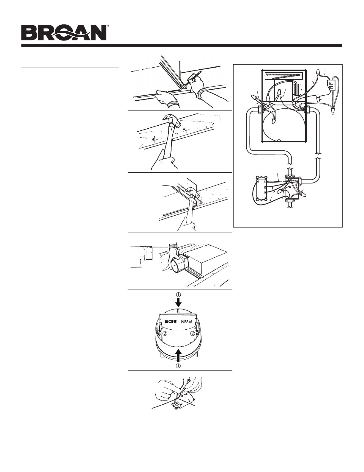
PREPARACIÓN
1. Asegúrese de que el conjunto del calentador esté desconectado del receptáculo ROJO.
2. Afloje los dos tornillos retenedores por el interior de la abertura de descarga del calentador. Coloque la punta
de un destornillador entre la pared exterior de la abertura de la descarga y la cubierta del ventilador. Haga
palanca hacia afuera con suavidad hasta que la descarga de la extracción se deslice del reborde de apoyo
sobre la cubierta exterior. (FIG. 1)
3. Desenganche los pasadores de la bisagra y levante el conjunto del calentador de la cubierta. (FIG. 2)
PRECAUCIÓN: RETIRE EL ANILLO DE ENVÍO DE LA ENTRADA DEL CALENTADOR ANTES DE HACER FUNCIONAR
EL CALENTADOR.
4. Desconecte el conjunto del ventilador del receptáculo NEGRO.
5. Retire el tornillo de montaje y levante con cuidado el conjunto del ventilador de la cubierta. (FIG. 3)
6. Consulte el diagrama de cableado de la página siguiente. Retire los agujeros ciegos correspondientes insertando la
punta del destornillador en las ranuras y doblando hacia atrás y hacia adelante hasta romper las lengüetas. (FIG. 4)
7. Inserte los soportes de montaje ajustables en los canales del soporte de la cubierta. (FIG. 5)
Si desea consultar la declaración de garantía, repuestos de servicio,
apoyo técnico o para registrar su producto, visite nuestro sitio web
o llame: www.broan-nutone.com 800-558-1711.
AGUJEROS CIEGOS

Página 7
MODELOS BHFLED80 • BHF80
ROJO
BLANCO
NEGRO
TIERRA
TIERRA
ROJO
AZUL
BLANCO
NEGRO
LINEA DE ENTRADA DE 120 VCA
LUZ
RESPI-
RADERO
CALOR
ROJO
NEGRO
INSTALACIÓN
ADVERTENCIA: Para reducir el riesgo de incendio, no
almacene ni use gasolina u otros vapores y líquidos
flamables en las cercanías del calentador.
PRECAUCIÓN: Alta temperatura, riesgo de incendio,
mantenga los cables eléctricos, cortinas, muebles y otros
combustibles por lo menos a 3 pies (0.9 m) del frente
del calentador y lejos de los lados y la parte posterior.
8. Para obtener los mejores resultados, elija un sitio que
permita descargar el ventilador hacia el aire libre y
donde se requiera el tramo de conductos más corto
posible y el menor número de codos.
9. Coloque la unidad entre las vigas y extienda los soportes
de montaje. Coloque los soportes de manera que el
borde inferior de la cubierta quede al ras del cielo raso
acabado. Marque la parte superior de la ranura tipo
bocallave en los cuatro soportes de montaje. (FIG. 6)
10. Quite temporalmente la unidad y clave parcialmente
los clavos en las vigas en los cuatro lugares
marcados. (FIG. 7)
11. Cuelgue la unidad en los clavos. Mediante las guías de
medición estampadas, compruebe si la unidad quedará
al ras con el cielo raso acabado. Clave los clavos de
manera que queden bien ajustados. Para centros de
vigas anchas: Se puede usar un tornillo autorroscante
#8 x 3/8 para unir entre sí los soportes extendidos
y crear un montaje rígido. Para lograr un montaje
silencioso, doble los canales del soporte ajustadamente
alrededor de los soportes de montaje. (FIG. 8)
12. Conecte a presión el conector del regulador de
tiro/conducto en la cubierta. Asegúrese de que las
lengüetas del conector queden fijas en las ranuras
de la cubierta. (La parte superior del conector del
regulador de tiro/conducto quedará al ras con la
parte superior de la cubierta.) (FIG. 9)
NOTA: Asegúrese de que la tapa del regulador de tiro
esté colocada dentro del conector del conducto. Si
no lo está: Comprima la parte superior e inferior
del conector para volver a colocar la tapa en su
lugar. (FIG. 10)
El trabajo de instalación y el cableado eléctrico deben
estar a cargo de personal capacitado, de acuerdo con
todos los códigos y normas correspondientes, que
incluyen los códigos y las normas de construcción
especícos sobre protección contra incendios.
13. Cablee la unidad de acuerdo con la Figura 11.
14. Regrese a su lugar el conjunto del calentador que quitó en
el PASO 3 y conéctelo en el receptáculo ROJO. Encamine
los cables alejándolos de la entrada del ventilador.
15. Regrese a su lugar el conjunto del ventilador que quitó
en el PASO 5 y conéctelo en el receptáculo NEGRO.
FIG. 6
FIG. 7
FIG. 8
GUÍAS DE
MEDICIÓN
ESTAMPADAS
FIG. 9
AL RAS
FIG. 10
FIG. 11
NOTA
ENTRADA
PARA
CABLE
RANURA DE
DESENGANCHE
Si el interruptor* no está conectado apropiadamente y hay que
cambiar los cables:
1. Cada entrada para cable tiene una ranura de desenganche.
2. Meta un destornillador o clavo pequeño en la ranura de
desenganche al tiempo que saca el cable poco a poco.
3. NO jale ningún cable para sacarlo del interruptor, sin utilizar
la ranura de desenganche, porque podría dañar el interruptor.
*interruptor no incluido

Página 8
MODELOS BHFLED80 • BHF80
INSTALACIÓN
(CONTINUACIÓN)
PRECAUCIÓN: Para evitar la posibilidad de
sobrecalentamiento y/o incendio, la rejilla se debe
instalar tal como se muestra.
NOTA: La cubierta del ventilador (rejilla) BHF80 será
ligeramente diferente de lo que se muestra en las
ilustraciones.
16. Antes de instalar la cubierta del ventilador, conectar
la luz de su nueva cubierta (en cualquiera salida)
y seleccionar la temperatura de color LED con el
interruptor CCT. (FIG. 12)
17. Extender el tornillo de montaje lo más posible.
(FIG. 13)
18. Conectar el enchufe de la luz (el enchufe puede diferir
de lo mostrado). (FIG. 14)
19. Orientar el controlador LED de la cubierta de la luz
hacia el lado del ventilador. (FIG. 15)
20. Sujetar la cubierta colocando la varilla roscada sobre
el tornillo de montaje. Apretar a mano la varilla roscada
hasta que la cubierta sea sujetada con la superficie del
techo. (FIG. 16)
21. Acoplar la lente. (FIG. 17)
FIG. 12
FIG. 13
FIG. 14
FIG. 15
FIG. 16 FIG. 17

Página 9
MODELOS BHFLED80 • BHF80
FUNCIONAMIENTO
Antes de usar el calentador, asegúrese de que el calentador se haya
instalado adecuadamente de acuerdo con los pasos de instalación que
comienzan en la sección “PREPARACIÓN” en la página 5.

Página 10
MODELOS BHFLED80 • BHF80
MANTENIMIENTO
El usuario puede realizar las siguientes tareas de mantenimiento
y limpieza. Todos los demás servicios los debe realizar un técnico
autorizado. Si tiene preguntas, consulte a nuestro departamento de
servicio al cliente llamando al: 800-558-1711.
LUBRICACIÓN
El calentador está permanentemente lubricado y nunca necesitará ponerle
aceite ni desarmarlo.
LIMPIEZA
Limpie el calentador una vez al mes tal como sigue:
1. Apague la energía eléctrica en el panel de servicio.
2. Asegúrese de que el elemento de calefacción esté frío.
3. Use un aditamento con un cepillo suave para aspirar suavemente las
aberturas de la rejilla o limpie la rejilla con un paño suave.
4. Restaure la energía eléctrica.
PRECAUCIÓN: NUNCA SUMERJA EN AGUA LAS PIEZAS METÁLICAS
NI LAS ELÉCTRICAS.
1104032B
Page 11
MODÈLES BHFLED80 • BHF80
CHAUFFAGE / VENTILATEUR / ÉCLAIRAGE
LIRE CES DIRECTIVES ET LES CONSERVER
FIG. 1
FIG. 2
FIG. 3
FIG. 4
FIG. 5
VIS DE
RETENUE
GOND
INSTRUCTIONS IMPORTANTES
LIRE TOUTES LES INSTRUCTIONS AVANT D’INSTALLER OU D’UTILISER CET APPAREIL DE CHAUFFAGE.
Observez les directives ci-dessous afin de réduire les risques d’incendie, de choc électrique ou de blessures corporelles :
1. N’utilisez cet appareil que de la manière prévue par le fabricant. Si vous avez des questions,
communiquez avec le fabricant à l’adresse ou au numéro de téléphone indiqués dans la garantie.
2. Avant de procéder à l’entretien ou au nettoyage de l’appareil, coupez l’alimentation du panneau
électrique et verrouillez l’interrupteur principal afin d’empêcher que le courant ne soit accidentellement
rétabli. S’il est impossible de verrouiller l’interrupteur principal, fixez solidement un message
d’avertissement, par exemple une étiquette, sur le panneau électrique.
3. La pose de l’appareil et les travaux d’électricité doivent être effectués par des personnes qualifiées conformément à la
réglementation en vigueur, notamment les normes de la construction ayant trait à la protection contre les incendies.
4. Veillez à ne pas endommager le câblage électrique ou d’autres équipements non apparents lors de la
découpe ou du perçage du mur ou du plafond.
5. Cet appareil de chauffage devient chaud en fonctionnant. Pour ne pas vous brûler, évitez tout contact de la peau
nue avec les surfaces chaudes. Garder les objets combustibles, tels que les meubles, oreillers, articles de literie,
papiers, vêtements, rideaux, etc. à une distance d’au moins 0,9 m (3 pi) de l’avant de l’appareil de chauffage.
6. Il faut faire preuve d’une très grande prudence lorsque l’appareil est utilisé près d’enfants ou de personnes
handicapées ou lorsqu’il est utilisé par ceux-ci, de même que lorsqu’il fonctionne sans surveillance.
7. Ne faites pas fonctionner un appareil de chauffage s’il est défectueux. Débranchez l’alimentation au
panneau électrique et demandez à un électricien de l’examiner avant de le réutiliser.
8. Ne l’utilisez pas à l’extérieur.
9. Pour débrancher l’appareil de chauffage, mettez les commandes sur arrêt et coupez l’alimentation du
circuit au panneau électrique (ou utilisez l’interrupteur interne, s’il y en a un).
10. N’insérez et ne laissez pénétrer aucun corps étranger dans les ouvertures de ventilation ou de sortie
d’air au risque de provoquer un choc électrique, un incendie ou d’endommager l’appareil de chauffage.
11. Pour prévenir tout incendie possible, n’obstruez pas les prises d’air et les sorties de quelque manière que ce soit.
12. L’appareil de chauffage contient des pièces brûlantes et qui produisent des arcs ou des étincelles
à l’intérieur. Ne l’utilisez pas dans un endroit où de l’essence, de la peinture ou des vapeurs ou
liquides inflammables sont utilisés ou entreposés.
13. N’utilisez cet appareil de chauffage que tel qu’expliqué dans ce manuel. Toute autre utilisation non
recommandée par le fabricant peut provoquer un incendie, un choc électrique ou des blessures corporelles.
14. Ce produit doit être mis à la terre.
15. N’installez pas cet appareil au-dessus d’une douche ou d’une baignoire.
16. Ce produit est conçu pour une installation dans les plafonds jusqu’à une hauteur 12/12. Le raccord
de conduit doit pointer vers le haut. NE PAS MONTER CE PRODUIT DANS UN MUR.
17. Installez l’appareil de chauffage à au moins 15 cm (6 po) du sol ou d’un mur adjacent.
18. Ne pas brancher l’appareil de chauffage à un gradateur ou à une commande de vitesse.
19. Fournir un circuit séparé de 20 ampères. Utiliser un câble d’alimentation de calibre 12 conforme au code.
20. Pour une meilleure efficacité, installer l’appareil de chauffage pour que la chaleur soit dirigée vers
la baignoire ou la douche. Éviter de la diriger vers les murs ou les fenêtres.
CONSERVER CES INSTRUCTIONS
PRÉPARATION
1. Assurez-vous que l’appareil de chauffage soit débranché du réceptacle ROUGE.
2. Desserrez les deux vis de retenue à l’intérieur de la sortie d’air de l’appareil de chauffage. Placez la pointe
d’un tournevis entre la paroi externe de la sortie d’air et le boîtier du ventilateur. Forcez légèrement vers
l’extérieur jusqu’à ce que la sortie d’air se dégage du bord du boîtier extérieur. (FIG. 1)
3. Enlevez le gond et retirez l’assemblage de l’appareil de chauffage du boîtier. (FIG. 2)
ATTENTION: ENLEVEZ L’ANNEAU D’EXPÉDITION À L’ENTRÉE D’AIR DU VENTILATEUR DE L’APPAREIL
DE CHAUFFAGE AVANT DE L’UTILISER.
4. Débranchez l’assemblage du ventilateur du réceptacle NOIR.
5. Enlevez la vis de montage et retirez délicatement l’assemblage du ventilateur du boîtier. (FIG. 3)
6. Référez-vous au schéma électrique à la page suivante. Détachez l’/les ouverture(s) préamorcée(s)
appropriée(s) en insérant la lame d’un tournevis dans les fentes afin d’effectuer plusieurs torsions
qui permettront de casser les languettes. (FIG. 4)
7. Insérez les supports de montage ajustables dans les tiges de montage du boîtier. (FIG. 5)
Pour la déclaration de garantie, les pièces de rechange, l’assistance technique
ou pour enregistrer votre produit, veuillez visiter notre site web ou appeler :
www.broan-nutone.com ou 800-558-1711.
OUVERTURES PRÉAMORCÉES
Page 12
MODÈLES BHFLED80 • BHF80
ROUGE
BLANC
NOIR
ENTRÉE DE LIGNE 120 VCA
ÉCLAIRAGE
VENTILATEUR
CHAUFFAGE
MISE À LA
TERRE
ROUGE
NOIR
MISE À LA
TERRE
ROUGE
BLEU
BLANC
NOIR
INSTALLATION
AVERTISSEMENT : Pour réduire les risques
d’incendie, n’entreposez pas et n’utilisez pas de
l’essence ni des liquides ou vapeurs inflammables
à proximité de l’appareil de chauffage.
ATTENTION: Température élevée, risque
d’incendie, garder les fils électriques, rideaux,
meubles et autres combustibles à au moins
0,9 m (3 pi) du devant de l’appareil de chauffage
et loin des côtés et de l’arrière.
8. Pour de meilleurs résultats, choisissez un
emplacement permettant au ventilateur d’évacuer
vers l’extérieur avec un conduit droit et court.
9. Placez l’appareil entre les solives et étirez les
supports de montage. Placez les supports pour
que le bord inférieur du boîtier soit positionné à
ras avec le plafond fini. Marquez l’emplacement
de la fente supérieure sur les quatre supports
de montage. (FIG. 6)
10. Enlevez temporairement l’appareil et enfoncez
partiellement des clous dans les solives aux quatre
emplacements marqués précédemment. (FIG. 7)
11. Accrochez l’appareil sur les clous et utilisez les
guides de référence embossés pour vérifier
si l’appareil sera positionné à ras avec le
plafond fini. Enfoncez complètement les clous.
Pour les solives à large espacement : une vis
autotaraudeuse #8 x 3/8 peut être utilisée pour
joindre les supports étirés pour créer un support
rigide. Pour assurer une installation exempte de
bruit, pincez fermement les bords du guide sur
les supports de montage. (FIG. 8)
12. Fixez le clapet/raccord de conduit sur le boîtier.
Assurez-vous que les pattes sur le raccord de
conduit s’emboîtent dans les fentes du boîtier.
(La partie supérieure du clapet/raccord de
conduit sera à ras avec la partie supérieure du
boîtier.) (FIG. 9)
NOTE : Assurez-vous que le volet du clapet soit
en place à l’intérieur du raccord de conduit.
Si ce n’est pas le cas : Serrez les parties
supérieure et inférieure du raccord pour
remettre le volet en place. (FIG. 10)
La pose de l’appareil et les travaux d’électricité
doivent être effectués par des personnes
qualiées conformément à la réglementation
en vigueur, notamment les normes de la
construction ayant trait à la protection contre
les incendies.
13. Effectuez le raccordement électrique de
l’appareil tel qu’il est indiqué à la Figure 11.
14. Remettez l’assemblage de l’appareil de
chauffage enlevé à l’ÉTAPE 3 et branchez-le
dans le réceptacle ROUGE. Éloignez les câbles
de l’entrée d’air du ventilateur.
15. Remettez l’assemblage du ventilateur enlevé
à l’ÉTAPE 5 et branchez-le dans le réceptacle
NOIR.
FIG. 6
FIG. 7
FIG. 8
GUIDES DE
RÉFÉRENCE
EMBOSSÉS
FIG. 9
À RAS
FIG. 10
FIG. 11
NOTE
OUVERTURE
POUR CÂBLE
FENTE DE DÉBLOCAGE
Si l’interrupteur* n’a pas été câblé correctement et que les
câbles doivent être déplacés :
1. Chaque ouverture pour câble a une fente de déblocage.
2. Insérez un petit clou ou la lame d’un tournevis dans la fente
de déblocage tout en retirant délicatement le câble.
3. NE PAS tirer de câble hors de l’interrupteur sans utiliser la
fente de déblocage. L’interrupteur pourrait être endommagé.
*interrupteur non inclus
Page 13
MODÈLES BHFLED80 • BHF80
INSTALLATION (SUITE)
ATTENTION: Pour éviter la possibilité de
surchauffe et/ou d’incendie, la grille doit être
installée tel qu’illustré.
16. Avant d’installer le couvercle de ventilateur,
branchez la lumière de votre nouveau couvercle
(dans n’importe quelle prise) et sélectionnez la
température de couleur de votre choix à l’aide
du commutateur TCC. (FIG. 12)
17. Déployez la vis de montage autant que
possible. (FIG. 13)
18. Branchez la prise d’éclairage (la prise peut
différer de celle illustrée). (FIG. 14)
19. Orientez le pilote à DEL sur le couvercle de la
lumière vers le ventilateur. (FIG. 15)
20. Sécurisez le couvercle en vissant la tige de
montage sur la vis de montage. Serrez la
tige de montage à la main jusqu’à ce que le
couvercle soit bien fixé contre la surface du
plafond. (FIG. 16)
21. Fixez la lentille. (FIG. 17)
FIG. 12
FIG. 13
FIG. 14
FIG. 15
FIG. 16 FIG. 17
NOTE : Le couvercle de ventilateur (grille) BHF80
sera légèrement différent de ce qui est
illustré.

Page 14
MODÈLES BHFLED80 • BHF80
FONCTIONNEMENT
Avant d’utiliser l’appareil de chauffage, assurez-vous qu’il est
correctement installé selon les directives indiquées à partir de la section
"PRÉPARATION" à la page 11.

Page 15
MODÈLES BHFLED80 • BHF80
MAINTENANCE
L’utilisateur peut effectuer les tâches d’entretien et de nettoyage suivantes.
Tous les autres travaux doivent être confiés à un technicien agréé.
Pour toute question, veuillez vous adresser au service à la clientèle au :
800-558-1711.
LUBRIFICATION
Le moteur de l’appareil de chauffage est lubrifié en permanence et n’a
pas besoin d’être huilé ni démonté.
NETTOYAGE
Nettoyez l’appareil de chauffage une fois par mois comme suit :
1. Coupez le courant au panneau de service.
2. Assurez-vous que l’élément de chauffage est frais.
3. Enlevez la poussière des ouvertures de la grille à l’aide d’un aspirateur
muni d’une brosse à poils doux ou nettoyez-les à l’aide d’un chiffon.
4. Rétablissez l’alimentation.
ATTENTION : LES PIÈCES MÉTALLIQUES ET ÉLECTRIQUES NE DOIVENT
JAMAIS ÊTRE IMMERGÉES DANS L’EAU.
1104032B