DEHUMIDIFIER
USER MANUAL
PD15R-01AE
Please read this manual before use.

CONTENTS
SAFETY INFORMATION
OPERATING INSTRUCTION
CONTROL PANEL DESCRIPTION
OPERATING INSTRUCTION
USAGE OF WATER TANK
CONTINUOUS DRAINAGE
FILTER REMOVAL
MAINTENANCE INSTRUCTION
TROUBLESHOOTING
01-04
05
06
06
11
12
10
10
11

1
1. Do not use means to accelerate the defrosting
process or to clean, other than those
recommended by the manufacturer.
2. The appliance shall be stored in a room without
continuously operating ignition sources (for
example: open flames, an operating gas
appliance or an operating electric heater.)
3. Do not pierce or burn.
4. Be aware that refrigerants may not contain an
odour.
5. Appliance shall be installed, operated and
stored in a room with a f
loor area larger than 4m
2
6. Servicing shall be performed only as
recommended by the manufacturer.
7. The appliance shall be stored in a well- ventilated
area where the room size corresponds to the
room area as specified for operation.
8. All working procedure that affects safety means
shall only be carried by competent persons.
SAFETY INFORMATION

2
9. Please read the manual carefully before the first time
using this product, and storage the unit in safe place
to avoid electricity leakage, flaming or person injure.
10. Do not put this product in the water or any other
liquids.
11. If the supply cord is damaged, it must be replaced by
the manufacturer, its service agent or similarly
qualified persons in order to avoid a hazard..
12. Please ask professional service agent to repair the
product. Improper r
epair might cause damage to
users.
13. Disconnect the appliance from power supply before
moving or cleaning the product, and also when the
product is not in used.
14. Please operate the product with specified electricity
voltage.
15. Please use this product only for household appliance
and follow the designed purpose.
16. Do not put any stuff on the product.
17. In order to avoid water leakage, please clean the
water tank before moving the product.
18. Do not incline the p
roduct, or leaking water may
damage the product.
19. This appliance can be used by children aged from 8
years and above and persons with reduced
physical,sensory or mental capabilities or lack of
experience and knowledge if they have been given
supervision or instruction concerning use of the
appliance in a safe way and understand the hazards
involved. Children shall not play with the appliance.
Cleaning and user maintenance shall not be made by
children w
ithout supervision.

3
20. Please keep the product from the wall or other
barriers in a minimum distance of 50 cm.
21. The appliance shall be installed in accordance with
national wiring regulations.
22. The applicable operating temperature range for this
unit is 5-35
.
23. Do not operate your dehumidifier in a wet room such
as a bathroom or laundry room.
24. Spaces where refrigerant pipes shall be compliance
with national gas regulations.
Transportation, marking and storage for units
1. Transport of equipment containing flammable
refrigerants Compliance with the transport
regulations
2. Marking of equipment using signs
Compliance with local regulations
3. Disposal of equipment using flammable
refrigerants Compliance with national
regulations
4. Storage of equipment/appliances The storage
of equipment should be in accordance with
the manufacturer’s instructions.
5. Storage of packed (unsold) equipment
Storage package protection should be
constructed such that mechanical damage to
the equipment inside the package will not
cause a leak of the refrigerant charge. The

4
maximum number of pieces of equipment
permitted to be stored together will be
determined by local regulations.
6. The appliance shall be stored so as to prevent
mechanical damage from occurring.
7. General work area
All maintenance staff and others working in the
local area shall be instructed on the nature of work
being carried out. Work in confined spaces shall
be avoided. The area around the workspace shall
be sectioned off. Ensure that the conditio
ns within
the area have been made safe by control of
flammable material.
5
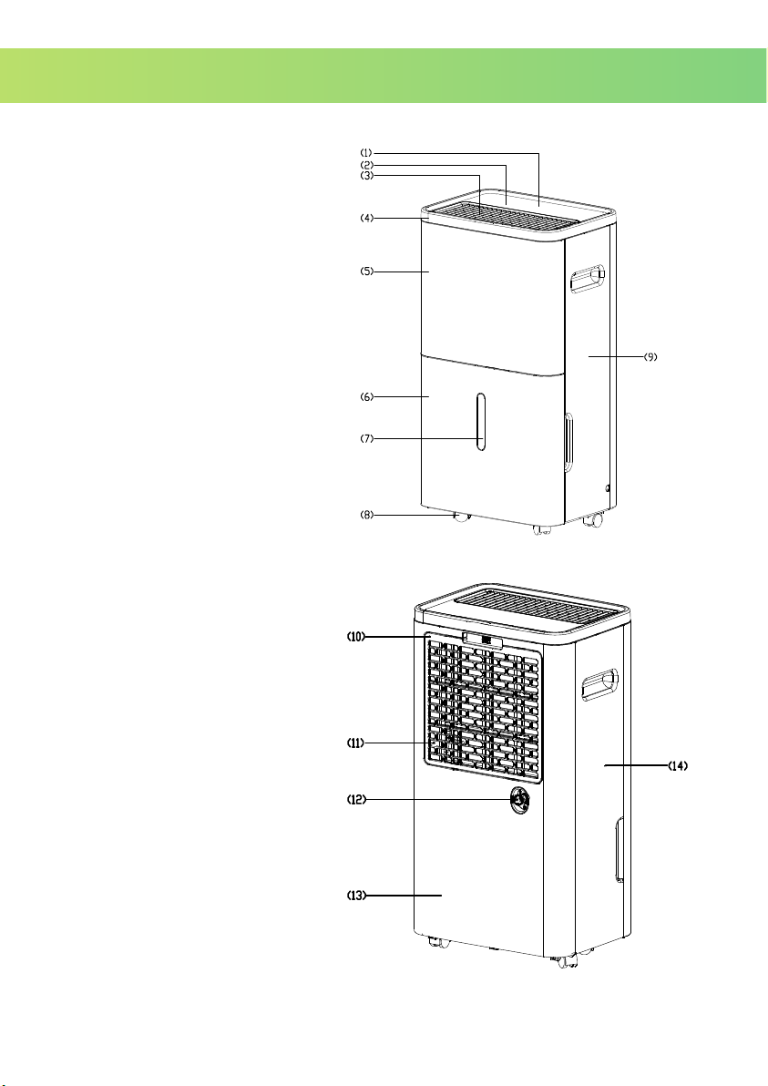
1. 7-Segment Display
2. Control panel
3. Air outlet
4. Top Cover
5. Front Case
6. Water Tank
7. Water Level Window
8. Castors
9. Right Case
10. Filter Case
11. Air Inlet
12. Drain Hole
13. Back Case
14. Left Case
OPERATING INSTRUCTION
6
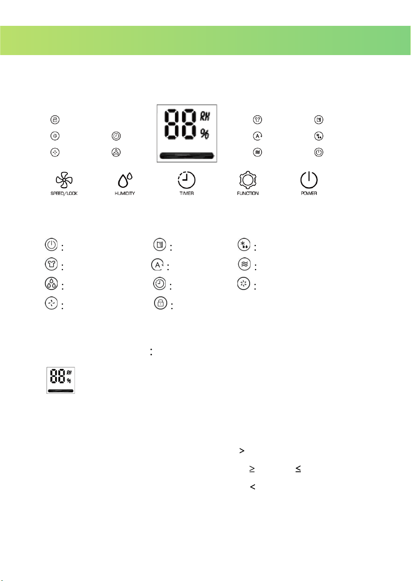
ICON INSTRUCTION
Operating Water Full Defrosting
Drying mode Auto Mode Fan Mode
Dehumidifying Timer High Fan Speed
Low Fan Speed Panel Lock
The Display
The 7-Segment Display: Indicates the setting humidity with "RH %” by
side; indicates timer’s timing time without "RH %” .
Light Bar “Red” : The ambient humidity
65%
Light Bar “Green” : The ambient humidity
45% to 65%
Light Bar “Yellow” : The ambient humidity
45%
OPERATING INSTRUCTION
CONTROL PANEL DESCRIPTION
7
1 POWER key:
Press POWER key to turn on/ turn off the unit. The Operating light
illuminates while the unit is working. The operating light goes dim while
the unit is turned off to stand-by mode.
2
FUNCTION key:
Switch from three modes: Clothes-Drying, Auto or Fan mode. In
Clothes-Drying or Auto mode, the compressor indicating light illuminates
when compressor is working; the light distinguished when the
compressor stops working.
The unit operates in Clothes-Drying mode while the first time plug-in. In
Clothes-Drying mode, the unit works in high fan speed ,and the
humidity cannot be adjusted.
Press FUNCTION key again, and then switch to Auto mode. The unit
detects the ambient humidity and operates automatically.
Press FUNCTI
ON key again, and then switch to Fan mode. Only the
motor works in Fan mode, the fan speed is available to change. The
compressor stops working.
3
HUMIDITY SETTING key
When the unit is either in Clothes-Drying, Auto or Fan mode, press the
HUMIDITY SETTING key would switch to Dehumidifying mode with
dehumidifying light illuminates. Press the key once, display shows the
present setting humidity; press again to accumulate(increase) the
setting humidity
Humidity setting range
30% 40% 50% … 80%.

8
After setting the humidity, the display switch back to show the ambient
humidity after 5 seconds.
4
FAN SPEED/ LOCK key:
The key has two functions: switch high/ low speed, and panel lock.
Switch the high/ low fan speed with the related light illuminates.
Deep press the LOCK key 3 seconds to activate the panel lock, the
indicating light illuminates, and then the panel cannot be controlled.
Press the key again for 3 seconds to cancel the lock and indicating
light, the pane resume controllable status.
5
TIMER SETTING key:
Press the key to set time you need. (1 to 24 hours)
Setting the timer in stand-by mode, the unit will be turned on
automatically; while setting timer in operating mode, the unit will be
turned off automatically.
If users press the POWER key to turn off/ on the unit before the timer
finishes counting down, the setting timer will be canceled.
While the timer is in used, the indicating light illuminates.
After setting the timer, the display switch back to show the ambient
humidity. Press TIMER key could show the setting time and timing time.
6. Water Full indicating light:
When the water tank is full, the unit stops operating and alarms with the
beeping sound and the indicating light. Please empty the water tank and
turn on the unit to resume working.

9
When the unit is defrosting, the indicating light illuminates. The motor
keeps operating but the compressor stops working.
WARNING
1. When operating the dehumidifier, please do not set the humidity higher
than ambient humidity.
2. When “Water Full” indicating light illuminates, please pour the water out
of the tank and put it back. Then the product will resume working.
3. When the product shut down, please wait at least 3 minutes before
restarting the unit to prevent damaging the compressor.
4. The applicable operatin
g temperature range for this unit is 5-32 .
5. If the dehumidifier can’t start (the operating light does not illuminate), or
the dehumidifier shut down unreasonably, please make sure whether
the plug is connected firmly to power supply. If the plug and power
supply are in normal condition, please wait for 10 minutes before
restarting the unit (the unit takes 10 minutes to reposition). Please ask
your local distributor service station to repair if the unit still cannot be
turned on after 10 minutes.
6. When the dehumidifier is operating, it’s normal that the working
compressor cause som
e heat and bring the ambient temperature up.
7. When the product is defrosting, the related indicating light illuminates.
The compressor stops while defrosting but the motor keeps running.
7. Defrosting indicating light:
10
8. The unit shows the ambient humidity when it’s
operating. If the ambient humidity is higher
than RH90%, the display shows “HI”; if the
ambient humidity is lower than RH30%, the
display shows “LO”
DRAINING INSTRUCTION
Draining water can be storage in the water tank, or be
continuous drained by PVC tube.
(The PVC tube is not included in the product.)
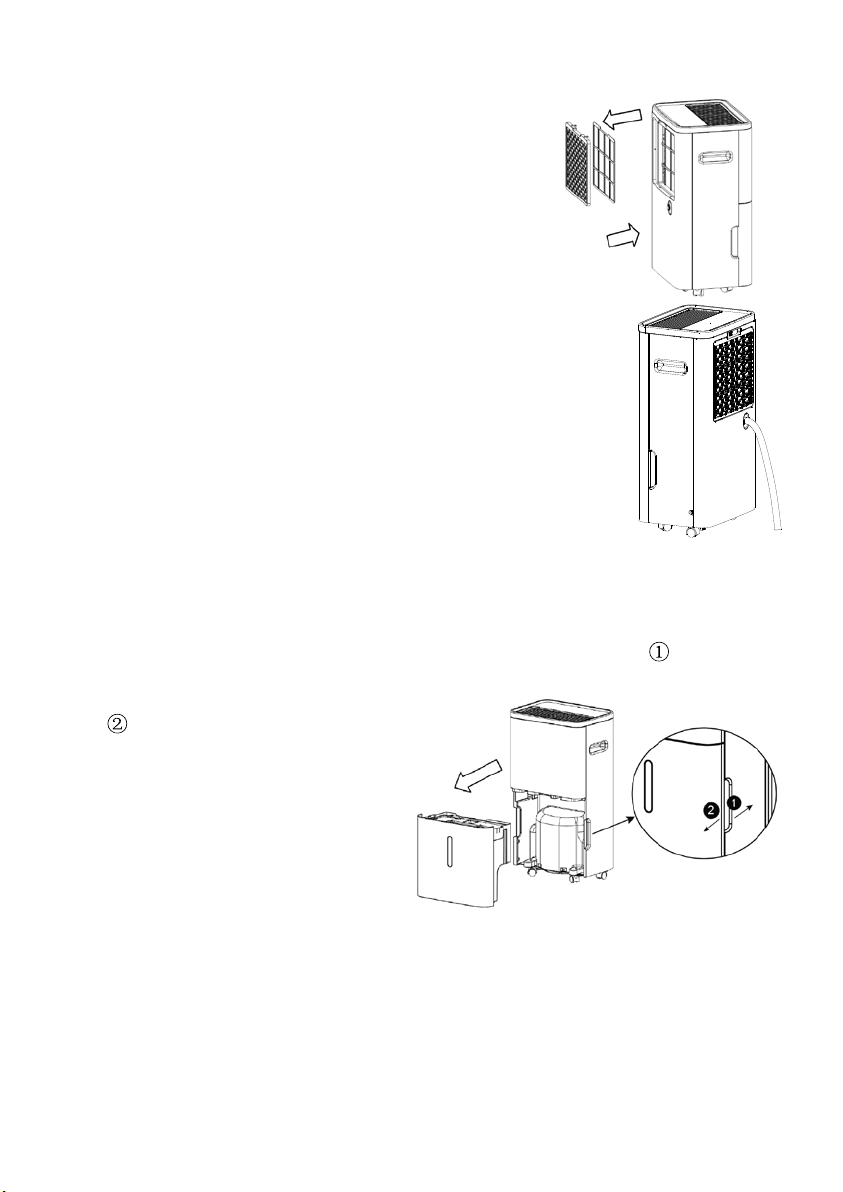
USAGE OF WATER TANK
When dehumidifying, the condensing water would be
drained into water tank. The unit stops working and illuminates the indicating
light when
the water tank is full of water. Please pour out the water that time.
1. To take out the water tank, please put the thumb on point
, and use
other fingers to pull the tank as
driection. After taking out
the tank, please pour the water
out.
2. Put the water tank back.
3. Press Power key to turn on the
unit.
CONTINUOUS DRAINAGE
1. Please take out the water tank to plug a PVC tube to draining hole. Then,
put the water tank back to enjoy the continuous draining.
2. Draining tube should be lower than draining hole to let water flow out.
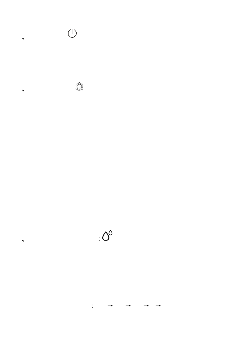
FILTER REMOVAL
11
1. Take the filter case and filter out together.
2. Remove the filter from filter case.
3. Wash the filter with cool water (cooler than 40
) every two weeks, and
put filter back after it air-dried naturally.
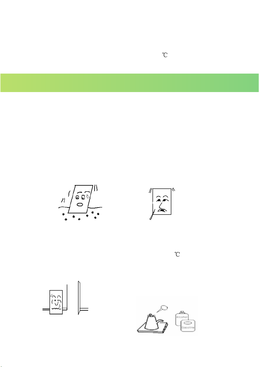
1.The unit is not allowed to be placed on surface which is soft or not flat. To
avoid the operating unit causes noise, vibration, and water/ electricity
leakage.
2.Never insert any slim rod or hard stuff into the unit which may damage the
unit.
3.Please disconnect the power cord to the power supply when you turn off
the unit or intend to stop using for long time.
4.To improve the performance of dehumidifier, please keep the unit in open
place, away from barriers
which may block the air.
5.Please wash the filter with cool water (lower than 40
) every two weeks.
(Note: Never use gasoline, alcohol or hot water to wash the filter.)
MAINTENANCE INSTRUCTION

12
1. Information on servicing
1) Checks to the area
Prior to beginning work on systems containing flammable refrigerants, safety
checks are necessary to ensure that the risk of ignition is minimised. For repair to
the refrigerating system, the following precautions shall be complied with prior to
conducting work on the system.
2) Work procedure
Work shall be undertaken under a controlled procedure so as to minimise the risk
of a flammable gas or vapour
being present while the work is being performed.
3) Checking for presence of refrigerant
The area shall be checked with an appropriate refrigerant detector prior to and
during work, to ensure the technician is aware of potentially flammable
atmospheres. Ensure that the leak detection equipment being used is suitable for
use with flammable refrigerants, i.e. non-sparking, adequately sealed or
intrinsically safe.
4) Presence of fire extinguisher
If any hot
work is to be conducted on the refrigeration equipment or any associated
parts, appropriate fire extinguishing equipment shall be available to hand. Have a
dry powder or CO2 fire extinguisher adjacent to the charging area.
5) No ignition sources
No person carrying out work in relation to a refrigeration system which involves
exposing any pipe work that contains or has contained flammable refrigerant shall
use any sources of ignition in such a manner that
it may lead to the risk of fire or
explosion. All possible ignition sources, including cigarette smoking, should be kept
sufficiently far away from the site of installation, repairing, removing and disposal,
during which flammable refrigerant can possibly be released to the surrounding
space. Prior to work taking place, the area
Troubleshooting

13
around the equipment is to be surveyed to make sure that there are no flammable
hazards or ignition risks. “No Smoking” signs shall be displayed.
6) Ventilated area
Ensure that the area is in the open or that it is adequately ventilated before
breaking into the system or conducting any hot work. A degree of ventilation shall
continue during the period that the work is carried out. The ventilation should safely
disperse any released refrigerant and preferably ex
pel it externally into the
atmosphere.
7) Checks to the refrigeration equipment
Where electrical components are being changed, they shall be fit for the purpose
and to the correct specification. At all times the manufacturer’s maintenance and
service guidelines shall be followed. If in doubt consult the manufacturer’s technical
department for assistance.
The following checks shall be applied to installations using flammable refrigerants:
– The charge size is
in accordance with the room size within which the refrigerant
containing parts are installed;
– The ventilation machinery and outlets are operating adequately and are not
obstructed;
– If an indirect refrigerating circuit is being used, the secondary circuit shall be
checked for the presence of refrigerant;
– Marking to the equipment continues to be visible and legible. Markings and signs
that are illegible shall be corrected;
– Refrigeration pipe or c
omponents are installed in a position where they are
unlikely to be exposed to any substance which may corrode refrigerant containing
components, unless the components are constructed of materials which are
inherently resistant to being corroded or are suitably protected against being so
corroded.
8) Checks to electrical devices

14
Repair and maintenance to electrical components shall include initial safety checks
and component inspection procedures. If a fault exists that could compromise
safety, then no electrical supply shall be connected to the circuit until it is
satisfactorily dealt with. If the fault cannot be corrected immediately but it is
necessary to continue operation, an adequate temporary solution shall be used.
This shall be reported to the owner of the equipment so all parties are ad
vised.
Initial safety checks shall include:
• That capacitors are discharged: this shall be done in a safe manner to avoid
possibility of sparking;
• That there no live electrical components and wiring are exposed while charging,
recovering or purging the system;
• That there is continuity of earth bonding.
2. Repairs to sealed components
1) During repairs to sealed components, all electrical supplies shall be disconnected from
the equipment being worke
d upon prior to any removal of sealed covers, etc. If it
isabsolutely. necessary to have an electrical supply to equipment during servicing, then
a permanently operating form of leak detection shall be located at the most critical
point to warn of a potentially hazardous situation.
2) Particular attention shall be paid to the following to ensure that by working on electrical
components, the casing is not altered in such a way that the level of pro
tection is
affected. This shall include damage to cables, excessive number of connections,
terminals not made to original specification, damage to seals, incorrect fitting of glands,
etc.
Ensure that apparatus is mounted securely.
Ensure that seals or sealing materials have not degraded such that they no longer serve
the purpose of preventing the ingress of flammable atmospheres. Replacement parts
shall be in accordance with the manufacturer’s sp
ecifications.
NOTE: The use of silicon sealant may inhibit the effectiveness of some types of leak

15
detection equipment. Intrinsically safe components do not have to be isolated
prior to working on them.
3. Repair to intrinsically safe components
Do not apply any permanent inductive or capacitance loads to the circuit without
ensuring that this will not exceed the permissible voltage and current permitted for the
equipment in use.
Intrinsically safe components are the only types that can be worked on while live in the
presence of a flammable atmosphere. The t
est apparatus shall be at the correct rating.
Replace components only with parts specified by the manufacturer. Other parts may
result in the ignition of refrigerant in the atmosphere from a leak.
4. Cabling
Check that cabling will not be subject to wear, corrosion, excessive pressure, vibration,
sharp edges or any other adverse environmental effects. The check shall also take
into account the effects of aging or continual vibration from sources such
as
compressors or fans.
5. Detection of flammable refrigerants
Under no circumstances shall potential sources of ignition be used in the searching for
or detection of refrigerant leaks. A halide torch (or any other detector using a naked
flame) shall not be used.
6. Leak detection methods
The following leak detection methods are deemed acceptable for systems containing
flammable refrigerants.
Electronic leak detectors shall be used to detect flammable refrigeran
ts, but the
sensitivity may not be adequate, or may need re-calibration. (Detection equipment
shall be calibrated in a refrigerant-free area.) Ensure that the detector is not a potential
source of ignition and is suitable for the refrigerant used. Leak detection equipment
shall be set at a percentage of the LFL of the refrigerant and shall be calibrated to the
refrigerant employed and the appropriate percentage of gas (25 % maximum) is

16
confirmed.
Leak detection fluids are suitable for use with most refrigerants but the use of
detergents containing chlorine shall be avoided as the chlorine may react with the
refrigerant and corrode the copper pipe-work.
If a leak is suspected, all naked flames shall be removed/ extinguished.
If a leakage of refrigerant is found which requires brazing, all of the refrigerant shall be
recovered from the system, or isolated (by means of shut of
f valves) in a part of the
system remote from the leak. Oxygen free nitrogen (OFN) shall then be purged
through the system both before and during the brazing process.
7. Removal and evacuation
When breaking into the refrigerant circuit to make repairs – or for any other
purpose –conventional procedures shall be used. However, it is important that best
practice is followed since flammability is a consideration. The following procedure
shall be adhered to:
• Remove
refrigerant;
• Purge the circuit with inert gas;
• Evacuate;
• Purge again with inert gas;
• Open the circuit by cutting or brazing.
The refrigerant charge shall be recovered into the correct recovery cylinders. The
system shall be “flushed” with OFN to render the unit safe. This process may need to
be repeated several times. Compressed air or oxygen shall not be used for this task.
Flushing shall be achieved by breaking the vacuum in the system wit
h OFN and
continuing to fill until the working pressure is achieved, then venting to atmosphere,
and finally pulling down to a vacuum. This process shall be repeated until no
refrigerant is within the system. When the final OFN charge is used, the system shall
be vented down to atmospheric pressure to enable work to take place. This operation
is absolutely vital if brazing operations on the pipe-work are to take place. Ensure that

17
the outlet for the vacuum pump is not close to any ignition sources and there is
ventilation available.
8. Charging procedures
In addition to conventional charging procedures, the following requirements shall be
followed.
– Ensure that contamination of different refrigerants does not occur when using
charging equipment. Hoses or lines shall be as short as possible to minimise the
amount of refrigerant contained in them.
– Cylinders shall be kept upright.
– Ensur
e that the refrigeration system is earthed prior to charging the system with
refrigerant.
– Label the system when charging is complete (if not already).
– Extreme care shall be taken not to overfill the refrigeration system. Prior to recharging
the system it shall be pressure tested with OFN. The system shall be
leak tested on completion of charging but prior to commissioning. A follow up leak
test shall be carried out prior to leaving the site.
9. Deco
mmissioning
Before carrying out this procedure, it is essential that the technician is completely
familiar with the equipment and all its detail. It is recommended good practice that all
refrigerants are recovered safely. Prior to the task being carried out, an oil and
refrigerant sample shall be taken in case analysis is required prior to re-use of
reclaimed refrigerant. It is essential that electrical power is available before the task is
commenced.
a) B
ecome familiar with the equipment and its operation.
b) Isolate system electrically.
c) Before attempting the procedure ensure that:
• Mechanical handling equipment is available, if required, for handling refrigerant
cylinders;

18
• All personal protective equipment is available and being used correctly;
• The recovery process is supervised at all times by a competent person;
• Recovery equipment and cylinders conform to the appropriate standards.
d) Pump down refrigerant system, if possible.
e) If a vacuum is not possible, make a manifold so that refrigerant can be removed from
various parts of the system.
f) Make sure that cylinder is situated on the scales before recover
y takes place.
g) Start the recovery machine and operate in accordance with manufacturer's
instructions.
h) Do not overfill cylinders. (No more than 80 % volume liquid charge).
i) Do not exceed the maximum working pressure of the cylinder, even temporarily.
j) When the cylinders have been filled correctly and the process completed, make sure
that the cylinders and the equipment are removed from site promptly and all isolation
valves on the equipme
nt are closed off.
k) Recovered refrigerant shall not be charged into another refrigeration system unless it
has been cleaned and checked.
10. Labelling
Equipment shall be labelled stating that it has been de-commissioned and emptied
of refrigerant. The label shall be dated and signed. Ensure that there are labels on
the equipment stating the equipment contains flammable refrigerant.
11. Recovery
When removing refrigerant from a system, either for servicing or d
ecommissioning, it
is recommended good practice that all refrigerants are removed safely.
When transferring refrigerant into cylinders, ensure that only appropriate refrigerant
recovery cylinders are employed. Ensure that the correct number of cylinders for
holding the total system charge is available. All cylinders to be used are designated
for the recovered refrigerant and labelled for that refrigerant (i.e. special cylinders for
the recovery of
refrigerant). Cylinders shall be complete with pressure relief valve

19
and associated shut-off valves in good working order. Empty recovery cylinders are
evacuated and, if possible, cooled before recovery occurs.
The recovery equipment shall be in good working order with a set of instructions
concerning the equipment that is at hand and shall be suitable for the recovery of
flammable refrigerants. In addition, a set of calibrated weighing scales shall be
available and in good working order. Hoses shall be complete
with leak-free
disconnect couplings and in good condition. Before using the recovery machine,
check that it is in satisfactory working order, has been properly maintained and that
any associated electrical components are sealed to prevent ignition in the event of a
refrigerant release. Consult manufacturer if in doubt.
The recovered refrigerant shall be returned to the refrigerant supplier in the correct
recovery cylinder, and the relevant Waste Transfer
Note arranged. Do not mix
refrigerants in recovery units and especially not in cylinders.
If compressors or compressor oils are to be removed, ensure that they have been
evacuated to an acceptable level to make certain that flammable refrigerant does not
remain within the lubricant. The evacuation process shall be carried out prior to
returning the compressor to the suppliers. Only electric heating to the compressor
body shall be employed to accelerate th
is process. When oil is drained from a system,
it shall be carried out safely.
Fuse parameters of the machine
Type: 524 or 5 H Voltage: 250V Current: 3.15 A
Problems Cause of problem Solution
E1
Temperature sensor error Contact the distributor service station
TROUBLE SHOOTING
20
SPECIFICATIONS
Model
Specification
PD15R-01AE
Power Supply 110V~60Hz
Power Input 310 W
Refrigerant R290, kg
Permissible Excessive Operating Pressure
Suction: 0.6MPa
Discharge 2.5MPa
Maximum Allowable Pressure 5.0MPa
Dimension (W x D x H) mm
315W x 230D x 590H
Applicable temperature
5
-35
Water Tank Capacity 6L
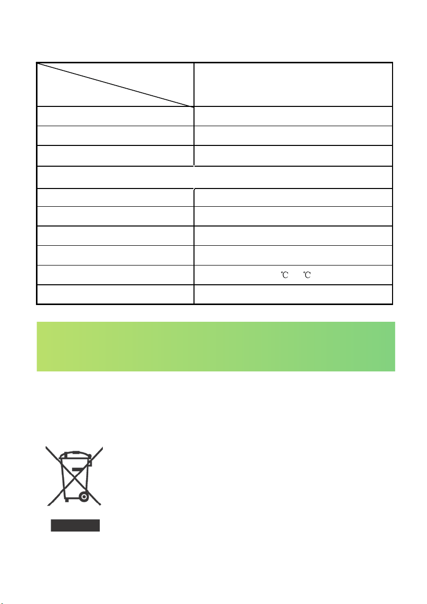
This marking indicates that this product should not be disposed
with other household wastes throughout the EU. To prevent
possible hazards to the environment or human health from
uncontrolled waste disposal, please recycle it to prove the
sustainable reuse of material resources. Please ask return and
collection systems or contact the retailer where the product was
purchased to return your used device, they can recycle products
safely.
Website link: https://www.colaze.com
Facebook homepage: Colaze Home
Email: [email protected]