
X7505200707
© 07/19 ECHO Incorporated
Operator’s
Manual
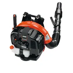
PB-580 H/T
Power Blower
The engine exhaust from this product contains chemicals
known to the State of California to cause cancer, birth defects,
or other reproductive harm.
Read and understand all provided literature before
use. Failure to do so could result in serious injury.
This product complies with CAN ICES-2/NMB-2.

TABLE OF CONTENTS PB-580 H/T
2 X7505200707
© 07/19 ECHO Incorporated
TABLE OF CONTENTS
Introduction ................................................................................................. 3
Servicing Information .................................................................................. 3
Parts/Serial Number............................................................................. 3
Service................................................................................................. 4
ECHO Consumer Product Support...................................................... 4
Product Registration ............................................................................ 4
Additional Literature............................................................................. 4
Safety.......................................................................................................... 4
Manual Safety Symbols and Important Information............................. 4
International Symbols .......................................................................... 5
Personal Condition and Safety Equipment .......................................... 7
Equipment.......................................................................................... 12
Emission Control (Exhaust & Evaporative) .............................................. 13
CARB And EPA Emissions Control Information ................................ 13
Description ................................................................................................ 14
Contents.................................................................................................... 18
Assembly................................................................................................... 19
Install Blower Pipes and Stick Handle .............................................. 19
Install Blower Pipes ........................................................................... 20
Operation .................................................................................................. 23
Fuel.................................................................................................... 24
Starting Warm Engine........................................................................ 28
Stopping Engine ................................................................................ 28
Operating Blower ............................................................................... 29
Cold Weather Operation .................................................................... 31
Adjust the Harness ............................................................................ 32
Maintenance ............................................................................................. 32
Skill Levels ......................................................................................... 33
Cooling System.................................................................................. 37
Carburetor Adjustment....................................................................... 41
Throttle Cable Adjustment ................................................................. 42
Troubleshooting ........................................................................................ 43
Storage ..................................................................................................... 45
Long Term Storage (Over 30 Days)................................................... 45
Specifications............................................................................................ 46
Product Registration.................................................................................. 48
Notes ........................................................................................................ 50
PB-580 H/T INTRODUCTION
X7505200707 3
© 07/19 ECHO Incorporated
INTRODUCTION
Specifications, descriptions and illustrative material in this literature are as
accurate as known at the time of publication, but are subject to change
without notice. Illustrations may include optional equipment and
accessories, and may not include all standard equipment.
Read and understand all provided literature.
Literature contains specifications and
information for safety, operation,
maintenance, storage and assembly specific
to this product. Scan QR codes for more
information.
For additional literature, including safety manuals where applicable, or
questions regarding terms used in this manual, visit:
https://www.echo-usa.com/manuals
OR
https://www.shindaiwa-usa.com/manuals
SERVICING INFORMATION
Parts/Serial Number
Genuine ECHO Parts and
Assemblies for your ECHO
products are available only from an
Authorized ECHO Dealer. When
you do need to buy parts always
have the Model Number and Serial
Number of the unit with you. For
future reference write them in the
space provided below.
Model No. _______________ Serial No. _______________

SAFETY PB-580 H/T
4 X7505200707
© 07/19 ECHO Incorporated
Service
Service of this product during the warranty period must be performed by an
Authorized ECHO Service Dealer. For the name and address of the
Authorized ECHO Service Dealer nearest you, ask your retailer or call:
1-800-432-ECHO (3246). Dealer information is also available on our Web
Site www.echo-usa.com. When presenting your unit for Warranty service/
repairs, proof of purchase is required.
ECHO Consumer Product Support
If you require assistance or have questions concerning the application,
operation, or maintenance of this product, call the ECHO Consumer
Product Support Department at 1-800-432-ECHO (3246) from 8:00 am to
5:00 pm (Central Standard Time) Monday through Friday. Before calling,
please know the model and serial number of your unit.
Product Registration
Register your ECHO equipment on-line at www.echo-usa.com or by filling
out the product registration sheet included in this manual. Registering your
product confirms warranty coverage and provides a direct link to ECHO if
we find it necessary to contact you.
Additional Literature
In addition to finding information online, information is available from your
Authorized ECHO Service Dealer, or by contacting ECHO Inc., 400
Oakwood Road, Lake Zurich, IL 60047 (1-800-432-ECHO (3246)).
SAFETY
Manual Safety Symbols and Important Information
Throughout this manual and on the product itself, you will find safety alerts
and helpful, informational messages preceded by symbols or key words.
The following is an explanation of those symbols and key words and what
they mean to you.
The safety alert symbol accompanied by the word “DANGER”
calls attention to an act or condition which WILL lead to serious
personal injury or death if not avoided.
PB-580 H/T SAFETY
X7505200707 5
© 07/19 ECHO Incorporated
The safety alert symbol accompanied by the word “WARNING”
calls attention to an act or condition which CAN lead to serious
personal injury or death if not avoided.
The safety alert symbol accompanied by the word “CAUTION”
calls attention to an act or condition which may lead to minor or
moderate personal injury if not avoided.
The enclosed message provides information necessary for the
protection of the unit.
Note: This enclosed message provides tips for use, care and
maintenance of the unit.
CIRCLE AND SLASH SYMBOL
This symbol means the specific action shown is prohibited.
Ignoring these prohibitions can result in serious or fatal injury.
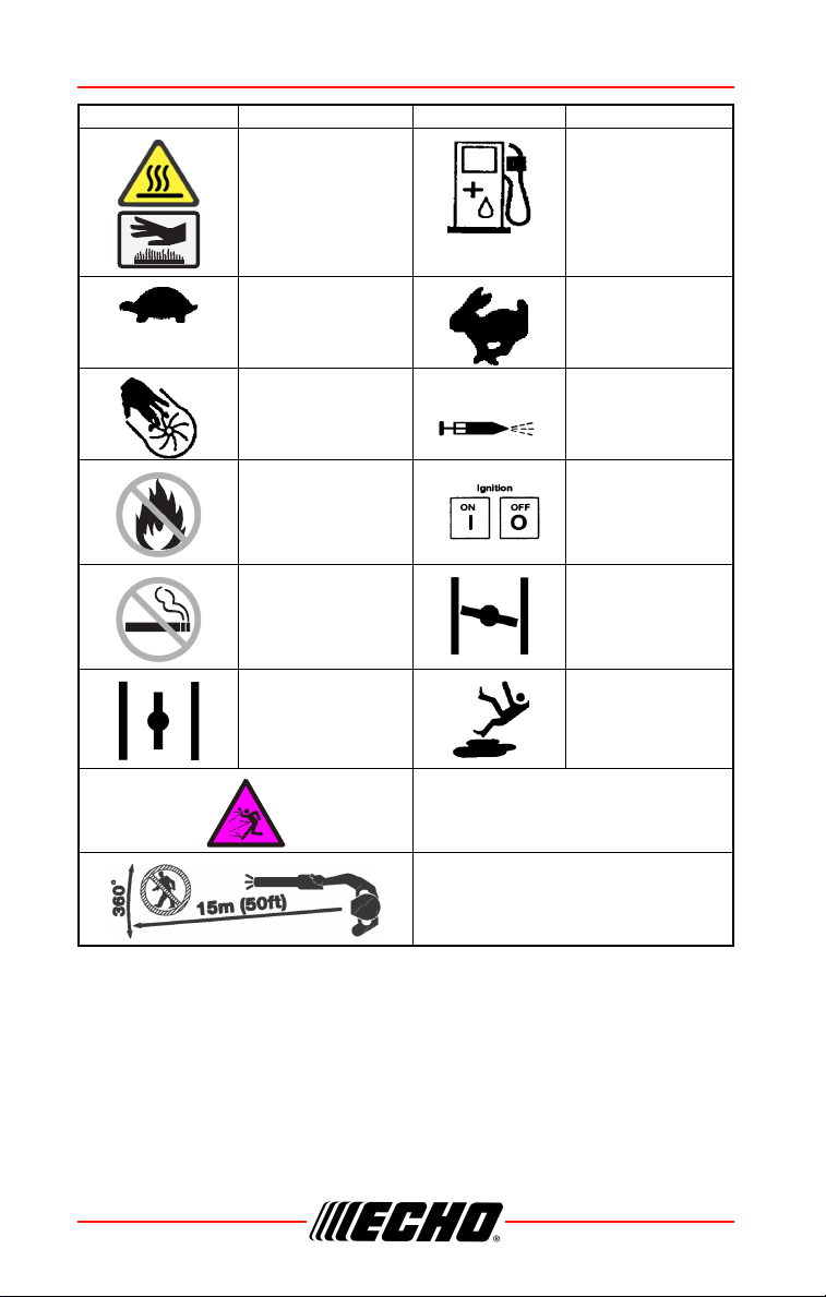
International Symbols
Symbol Description Symbol Description
Read and Understand
the Operator’s Manual
Carburetor Adjustment
- High Speed Mixture
Wear Eye, Ear and
Head Protection
Carburetor Adjustment
- Idle Speed
Wear Hand
Protection
Carburetor Adjustment
- Low Speed Mixture
Safety/Alert Emergency Stop
H
T
L
SAFETY PB-580 H/T
6 X7505200707
© 07/19 ECHO Incorporated
Hot Surface Fuel and Oil Mixture
Idle speed Fast speed
Finger severing Primer Bulb
DO NOT Allow Flames
or Sparks Near Fuel
Ignition
ON / OFF
DO NOT Smoke Near
Fuel
Choke Control “COLD
START” Position
(Choke Closed)
Choke Control “RUN”
Position (Choke Open)
Wear Slip Resistant
Footwear
Beware of thrown objects
Keep Bystanders and Helpers
Away 15 m (50 ft.).
Symbol Description Symbol Description
PB-580 H/T SAFETY
X7505200707 7
© 07/19 ECHO Incorporated
Personal Condition and Safety Equipment
Cancer and Reproductive Harm
www.P65Warnings.ca.gov
The muffler or catalytic muffler and surrounding cover
may become extremely hot. Always keep clear of
exhaust and muffler area, otherwise serious personal
injury may occur.
Users of this product risk injury to themselves and others if the
unit is used improperly and/or safety precautions are not
followed. Proper clothing and safety gear must be worn when
operating unit.
Physical Condition
Your judgment and physical dexterity may not be good:
• If you are tired or sick
• If you are taking medication
• If you have taken alcohol or drugs

SAFETY PB-580 H/T
8 X7505200707
© 07/19 ECHO Incorporated
Operate unit only if you are physically and mentally well.
Eye Protection
◆ Eye protection that meets ANSI Z87.1 or CE requirements
must be worn whenever you operate the unit.
◆ For additional safety, a full-face shield may be worn over
safety glasses or goggles to provide protection from sharp
branches or flying debris.
Hand Protection
Wear sturdy, no-slip, rubber work gloves to improve your grip on the
handles. Gloves also provide protection against cuts and scratches, cold
environments, and reduce the transmission of machine vibration to your
hands.
Hearing/Ear Protection
ECHO recommends wearing personal protection whenever unit is used.
Breathing Protection
Operators who are sensitive to dust or other common airborne allergens
may need to wear a dust mask to prevent inhaling these materials while
operating unit. Dust masks can provide protection against dust, plant debris,
and other plant matter such as pollen. Make sure the mask does not impair
your vision, and replace the mask as needed to prevent air restrictions.
Proper Clothing
Wear snug-fitting, durable clothing:
• Pants should have long legs, shirts should have long sleeves.
• DO NOT WEAR SHORTS.
• DO NOT WEAR TIES, SCARVES, JEWELRY, or clothing with loose or
hanging items that could become entangled in moving parts or
surrounding growth.
• Keep clothing buttoned or zipped, and keep shirt tails tucked in.
Wear sturdy work shoes with nonskid rubber soles:
• DO NOT WEAR OPEN TOED SHOES.
• DO NOT OPERATE UNIT BAREFOOTED.

PB-580 H/T SAFETY
X7505200707 9
© 07/19 ECHO Incorporated
Keep long hair away from engine and air intake. Retain hair with cap or net.
Heavy protective clothing can increase operator fatigue, which may lead to
heat stroke. Schedule heavy work for early morning or late afternoon hours
when temperatures are cooler.
The components of this machine generate an electromagnetic
field during operation, which may interfere with some
pacemakers. To reduce the risk of serious or fatal injury,
persons with pacemakers should consult with their physician
and the pacemaker manufacturer before operating this
machine. In the absence of such information, ECHO does not
recommend the use of this machine by anyone who has a
pacemaker.
Extended Operation / Extreme Conditions
Prolonged exposure to cold and/or vibration may result in
injury. Read and follow all safety and operation instructions to
minimize risk of injury. Failure to follow instructions may result
in painful wrist/hand/arm injuries.
It is believed that a condition called Raynaud’s Phenomenon, which affects
the fingers of certain individuals, may be brought about by exposure to
vibration and cold. Exposure to vibration and cold may cause tingling and
burning sensations, followed by loss of color and numbness in the fingers.
The following precautions are strongly recommended, because the
minimum exposure, which might trigger the ailment, is unknown.
• Keep your body warm, especially the head, neck, feet, ankles, hands, and
wrists.
• Maintain good blood circulation by performing vigorous arm exercises
during frequent work breaks, and also by not smoking.
• Limit the hours of operation. Try to fill each day with jobs where operating
the unit or other hand-held power equipment is not required.
• If you experience discomfort, redness, and swelling of the fingers followed
by whitening and loss of feeling, consult your physician before further
exposing yourself to cold and vibration.
SAFETY PB-580 H/T
10 X7505200707
© 07/19 ECHO Incorporated
Repetitive Stress Injuries (RSI)
It is believed that overusing the muscles and tendons of the fingers, hands,
arms, and shoulders may cause soreness, swelling, numbness, weakness,
and extreme pain in those areas. Certain repetitive hand activities may put
you at a high risk for developing a Repetitive Stress Injury (RSI). An extreme
RSI condition is Carpal Tunnel Syndrome (CTS), which could occur when
your wrist swells and squeezes a vital nerve that runs through the area.
Some believe that prolonged exposure to vibration may contribute to CTS.
CTS can cause severe pain for months or even years.
To reduce the risk of RSI/CTS, do
the following:
• Avoid using your wrist in a bent,
extended, or twisted position.
Instead try to maintain a straight
wrist position. Also, when
grasping, use your whole hand,
not just the thumb and index
finger.
• Take periodic breaks to minimize
repetition and rest your hands.
• Reduce the speed and force with
which you do the repetitive
movement.
• Do exercises to strengthen the hand and arm muscles.
• Immediately stop using all power equipment and consult a doctor if you
feel tingling, numbness, or pain in the fingers, hands, wrists, or arms. The
sooner RSI/CTS is diagnosed, the more likely permanent nerve and
muscle damage can be prevented.
All over head electrical conductors and communications wires
can have electricity flow with high voltages. This unit is not
insulated against electrical current. Never touch wires directly
or indirectly, otherwise serious injury or death may result.

PB-580 H/T SAFETY
X7505200707 11
© 07/19 ECHO Incorporated
Do not operate this product indoors or in inadequately
ventilated areas. Engine exhaust contains poisonous emissions
and can cause serious injury or death.
Read the Manual
• Provide all users of this equipment with literature for instructions on safe
operation.
Clear the Work Area
• Clear the area of children, bystanders, and pets. At a minimum, keep all
children, bystanders, and pets outside a 15 m (50 ft.) radius; outside the
15 m (50 ft.) zone, there is still a risk of injury from thrown objects.
Bystanders should be encouraged to wear eye protection. If you are
approached, stop the engine.
• Avoid blowing debris towards people, pets, open windows, or vehicles
when using unit.
• Review area to be cleared. Look for potential hazards such as stones or
metal objects.
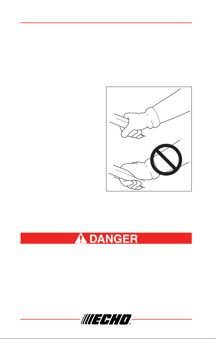
Keep a Firm Grip
• To prevent from dropping the unit, hold the handle in one hand, with
thumb and fingers encircling the handle.
Keep a Solid Stance
• Maintain footing and balance at all times. Do not stand on slippery,
uneven or unstable surfaces. Do not work in odd positions or on ladders.
Do not over reach.
Avoid Hot Surfaces
• Keep exhaust area clear of flammable debris.
Avoid contact during and immediately after
operation.

SAFETY PB-580 H/T
12 X7505200707
© 07/19 ECHO Incorporated
Equipment
Use only approved attachments. Serious injury may result from
the use of a non-approved attachment combination. ECHO, INC.
will not be responsible for the failure of cutting devices,
attachments or accessories which have not been tested and
approved by ECHO. Read and comply with all safety
instructions listed in this manual.
◆ Check unit for loose/missing nuts, bolts, and screws.
Tighten and/or replace as needed.
◆ Do not use blower if any part is missing or damaged.
◆ Have repairs done only by an authorized service dealer.
Moving parts can amputate fingers or cause severe injuries.
Keep hands, clothing and loose objects away from all openings.
◆ ALWAYS stop engine, disconnect spark plug, and make
sure all moving parts have come to a complete stop before
removing obstructions, clearing debris, or servicing unit.
◆ DO NOT start or operate unit unless all guards and
protective covers are properly assembled to unit.
◆ NEVER reach into any opening while the engine is running.
Moving parts may not be visible through openings.
Periodically Check fuel system (fuel lines, vent, grommet, fuel
tank, and fuel cap) for leaks especially if the unit is dropped. If
damage or leaks are found, do not use unit, otherwise serious
personal injury or property damage may occur. Have unit
repaired by an authorized servicing dealer before using.
PB-580 H/T EMISSION CONTROL
X7505200707 13
© 07/19 ECHO Incorporated
EMISSION CONTROL (EXHAUST &
EVAPORATIVE)
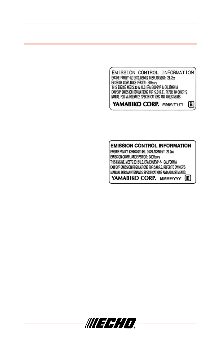
CARB And EPA Emissions Control Information
The emission control system for
the engine is EM (engine
modification) and, if the second to
last character of the Engine Family
on the Emission Control
Information label (sample below) is
“B”, “C”, “K”, or “T”, the emission
control system is EM and TWC (3-
way catalyst). The fuel tank/fuel
line emission control system is EVAP (evaporative emissions). Evaporative
emissions for California models are only applicable to fuel tanks and fuel
feed lines.
An Emission Control Label is
located on the engine. (This is an
EXAMPLE ONLY, information on
label varies by engine FAMILY).
Product Emission Durability
(Emission Compliance
Period)
The 50 or 300 hour emission compliance period is the time span selected by
the manufacturer certifying the engine emissions output meets applicable
emissions regulations, provided that approved maintenance procedures are
followed as listed in the Maintenance Section of this manual.
DESCRIPTION PB-580 H/T
14 X7505200707
© 07/19 ECHO Incorporated
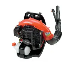
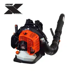
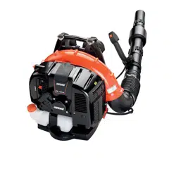
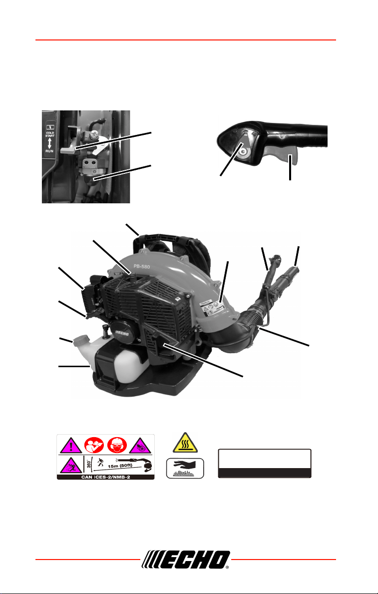
DESCRIPTION
PB-580 H
Locate the safety decal(s) on your unit. Make sure the decal(s) is legible and
that you understand and follow the instructions on it. If a decal cannot be
read, a new one can be ordered from your ECHO dealer. The safety decal is
for example only. Your label may appear slightly different.
2
3
4
5
6
7
8
9
10
11
12
13
1
14
15
70dB(A)
per ANSI B175.2

PB-580 H/T DESCRIPTION
X7505200707 15
© 07/19 ECHO Incorporated
1. Handle
2. Throttle Position Lever/stop Switch
3. Spark Plug
4. Shoulder Harness
5. Safety Decal
6. Stick Handle
7. Blower Pipes
8. Flexible Pipes
9. Spark Arrestor Muffler (with or without Catalyst)
10. Fuel Tank
11. Fuel Tank Cap
12. Recoil Starter Handle
13. Air Cleaner
14. Choke
15. Purge Bulb
DESCRIPTION PB-580 H/T
16 X7505200707
© 07/19 ECHO Incorporated
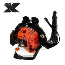
PB-580T
Locate the safety decal(s) on your unit. Make sure the decal(s) is legible and
that you understand and follow the instructions on it. If a decal cannot be
read, a new one can be ordered from your ECHO dealer. The safety decal is
for example only. Your label may appear slightly different.
1
2
3
4
5
6
7
8
9
10
11
12
13
14
15
70dB(A)
per ANSI B175.2

PB-580 H/T DESCRIPTION
X7505200707 17
© 07/19 ECHO Incorporated
1. Shoulder Harness
2. Safety Decal
3. Throttle Control
4. Blower Pipes
5. Flexible Pipes
6. Spark Arrestor Muffler (with or without Catalyst)
7. Fuel Tank
8. Fuel Tank Cap
9. Recoil Starter Handle
10. Air Cleaner
11. Spark Plug
12. Choke
13. Purge Bulb
14. Throttle Position Lever
15. Throttle Switch

CONTENTS PB-580 H/T
18 X7505200707
© 07/19 ECHO Incorporated
CONTENTS
The ECHO product you purchased has been factory pre-assembled for your
convenience. Due to packaging restrictions, some assembly may be
necessary.
After opening the carton, check for damage. Immediately notify your retailer
or ECHO Dealer of damaged or missing parts. Use the contents list to check
for missing parts.
PB-580 H
PB-580 T
1 Power Head
1Flex Pipe
1 Pipe With Swivel
1 Straight Pipe
1 Straight Pipe With Decal
1 Operator's Manual
1 Warranty Statement
2 Clamps With Screws
1 Stick Handle
1 Bolt 6 x 45 mm
1 Washer 6 mm
1 Wing nut
1 Power Head
1Flex Pipe
1 Pipe With Swivel
1 Straight Pipe
1 Straight Pipe With Decal
1 Operator's Manual
1 Warranty Statement
2 Clamps With Screws
PB-580 H/T ASSEMBLY
X7505200707 19
© 07/19 ECHO Incorporated
ASSEMBLY
PB-580 H
Never perform maintenance or assembly procedures with
engine running or serious personal injury may result.
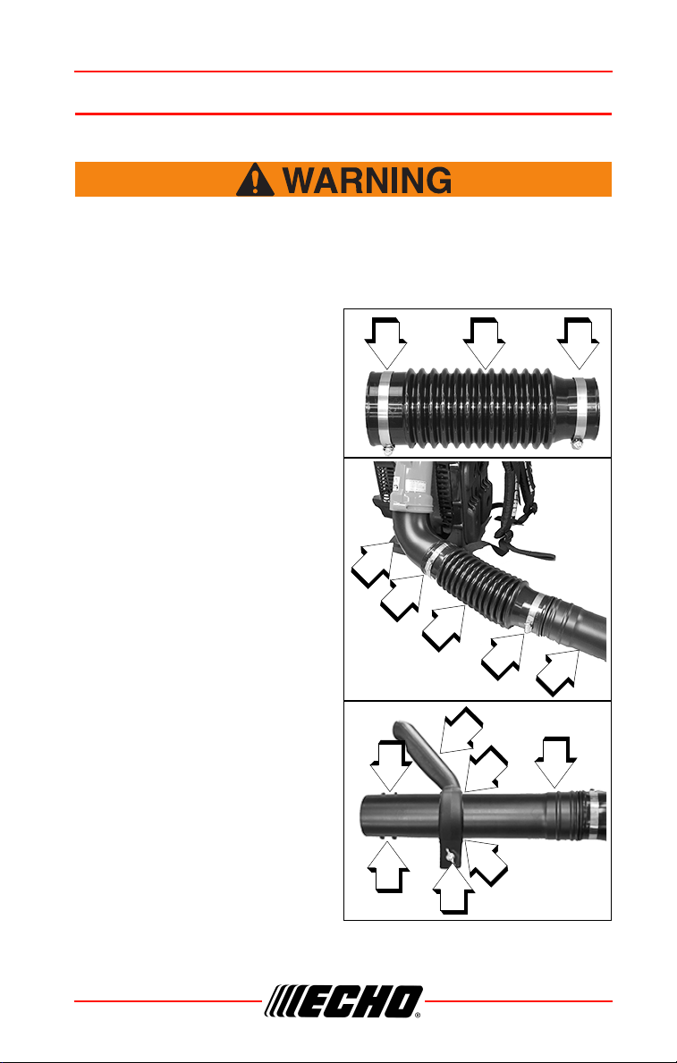
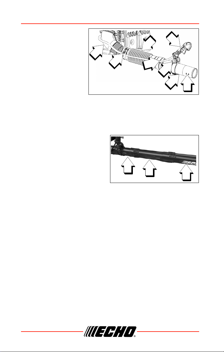
Install Blower Pipes and Stick Handle
1. Assemble clamps (A) onto both
ends of flexible pipe (B).
2. Assemble straight pipe with
swivel (C) into flexible pipe (B).
3. Assemble flexible pipe (B) to
elbow (D) on blower and tighten
clamps (A).
Note: A light lubricant may be
used to ease assembly of
flexible pipe to blower
elbow.
4. Loosen wing nut (E) completely
and expand stick handle clamp
(F). Align notches (G) in handle
clamp with tabs (H).
5. Slide stick handle onto swivel
pipe (C). Stick handle (F)
should be angled away from
operator.
6. Position stick handle (F) for
comfortable operation. Tighten
wing nut (E).
A AB
C
A
B
D
C
A
H
H
F
G
C
E
G
ASSEMBLY PB-580 H/T
20 X7505200707
© 07/19 ECHO Incorporated
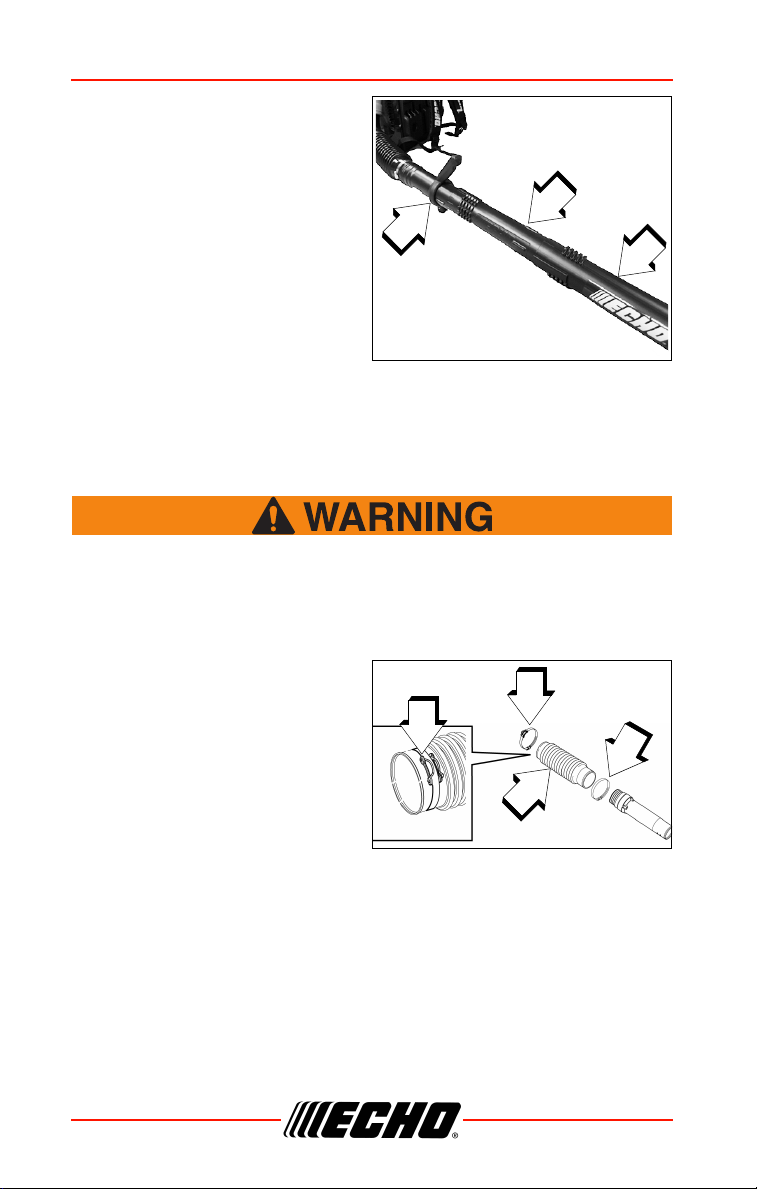
7. Assemble straight pipe (J) onto
swivel pipe (C), until you feel
light resistance. Hold swivel
pipe and turn straight pipe
clockwise, engaging positive
locking channels, until
connection is firm. Do not force
connection.
8. Assemble straight pipe with
decal (K) to straight pipe (J) as
in step 7.
Note: Blower use will eventually
loosen pipe connections.
Exclusive positive locking
system allows pipes to be tightened. If loosening occurs,
remove two straight pipes and install according to instructions
7 & 8.
PB-580T
Never perform maintenance or assembly procedures with
engine running or serious personal injury may result.
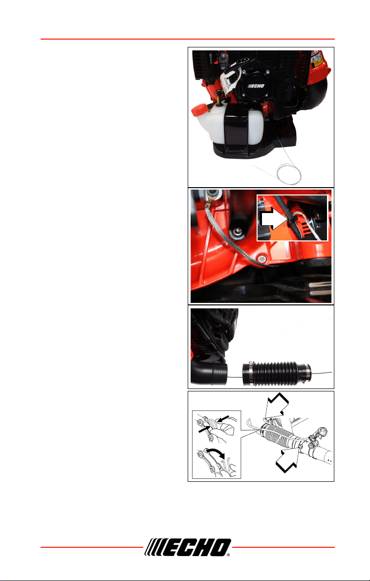
Install Blower Pipes
1. Assemble clamps (A) and (G)
onto both ends of flexible pipe
(B).
Note: Clamp with cable guide
loop (G) fits elbow end of
flexible pipe.
J
C
K
G
G
A
B
PB-580 H/T ASSEMBLY
X7505200707 21
© 07/19 ECHO Incorporated
Note: Anti-static wire before
installation.
2. Route anti-static wire below fan
housing and clip wire into
throttle cable retaining clip (X).
Position wire outside blower
elbow.
3. Insert anti-static wire through
flex tube. Leave enough slack
in anti-static wire to allow for full
rotation of elbow.
Note: A light lubricant may be
used to ease assembly of
flexible pipe to blower
elbow.
4. Assemble flexible pipe to elbow
(D) on blower. Position clamp
with cable guide loop (G) on
outside of flexible pipe and
tighten clamp.
Note: Hang handle freely from
blower to assure throttle
cable is not twisted before
installing handle (E).
X
G
D
ASSEMBLY PB-580 H/T
22 X7505200707
© 07/19 ECHO Incorporated
5. Position throttle cable
along the outside of
elbow. Loosen knob
(H) on handle (E).
Align notches in
handle with tabs (F)
and install onto swivel
pipe (C) past long
ridges in pipe.
6. Insert anti-static wire
through swivel pipe
(wire will hang freely
in pipe).
7. Assemble swivel pipe into flexible pipe and tighten clamp (A).
8. Clip throttle cable into throttle cable guide loop.
9. Move handle (E) to desired position. Tighten knob (H) hand tight.
10. Assemble straight pipe (K) onto
swivel pipe, until you feel light
resistance. Hold swivel pipe
and turn straight pipe
clockwise, engaging positive
locking channels, until
connection is firm. Do not force
connection.
11. Assemble straight pipe with
decal (J) to straight pipe as in step 10.
Note: Blower use will eventually loosen pipe connections. Exclusive
positive locking system allows pipes to be tightened. If
loosening occurs, remove two straight pipes and install
according to instructions 10 & 11.
D
G
B
H
A
C
F
E
K
J
C

PB-580 H/T OPERATION
X7505200707 23
© 07/19 ECHO Incorporated
OPERATION
Moving parts can amputate fingers or cause severe injuries.
Keep hands, clothing and loose objects away from all openings.
Always stop engine, disconnect spark plug, and make sure all
moving parts have come to a complete stop before removing
obstructions, clearing debris, or servicing unit. Blower housing
may contain shredder blades and other sharp edges that can
cause serious injuries if touched, even if engine is off and
blades are not moving. Wear gloves to protect hands from sharp
edges and hot surfaces.
Operation of this equipment may create sparks that can start
fires around dry vegetation. This unit is equipped with a spark
arrestor to prevent discharge of hot particles from the engine.
Contact local fire authorities for laws or regulations regarding
fire prevention requirements.
Engine exhaust IS HOT, and contains Carbon Monoxide (CO), a
poison gas. Breathing CO can cause unconsciousness, serious
injury, or death. Exhaust can cause serious burns. ALWAYS
position unit so that exhaust is directed away from your face
and body.
◆ Always maintain a direct, clear line of site to the unit and
the work being performed.
◆ Always be alert for changes in operation of unit.
◆ Always shut engine off before transporting unit to new
location.

OPERATION PB-580 H/T
24 X7505200707
© 07/19 ECHO Incorporated
Fuel
Diesel fuels and alternative fuels, such as E-15 (15% ethanol),
E -85 (85% ethanol) or any fuels not meeting ECHO
requirements are NOT approved for use in ECHO 2-stroke
gasoline engines. Use of diesel or alternative fuels may cause
performance problems, loss of power, overheating, fuel vapor
lock, and unintended machine operation, including, but not
limited to, improper clutch engagement. Diesel or alternative
fuels may also cause premature deterioration of fuel lines,
gaskets, carburetors and other engine components.
Fuel Requirements
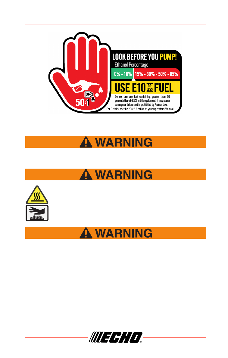
Gasoline - Use 89 Octane [R+M/2] (mid grade or higher) gasoline known to
be good quality. Gasoline may contain up to 10% Ethanol (grain alcohol) or
15% MTBE (methyl tertiary-butyl ether). Gasoline containing methanol
(wood alcohol) is NOT approved. Use of ECHO branded fuel is
recommended to extend engine life in all air-cooled 2-stroke and 2/4-stroke
hybrid engines.
Two Stroke Oil - A two-stroke engine oil, such as ECHO branded 2-stroke
oils, meeting ISO-L-EGD (ISO/CD 13738) and J.A.S.O. FD
Standards must
be used. ECHO branded 2-stroke oils meet these standards. Engine
problems due to inadequate lubrication caused by failure to use an ISO-L-
EGD (ISO/CD 13738) and J.A.S.O. M345-FD
certified oil will void the two-
stroke engine warranty.
2-Stroke engine oil contains petroleum distillates and other
additives that may be harmful if swallowed. Heated oil can
release vapors that can cause flash fire, or ignite with explosive
force. Read and follow the oil manufacturer’s instructions, and
observe all safety warnings and precautions for handling
flammable liquids. For more detailed safety and first aid
information, visit www.echo-usa.com for a copy of the Material
Safety Data Sheet.
◆ KEEP OUT OF REACH OF CHILDREN.
◆ If swallowed, do not induce vomiting. CALL PHYSICIAN OR
A POISON CONTROL CENTER IMMEDIATELY.
◆ WEAR SAFETY GLASSES when mixing or handling.

PB-580 H/T OPERATION
X7505200707 25
© 07/19 ECHO Incorporated
◆ AVOID repeated or prolonged skin contact.
◆ AVOID inhaling oil mists or vapors.
ECHO branded 2-stroke oils may be mixed at 50:1 ratio for
application in all ECHO engines sold in the past regardless of ratio
specified in those manuals.
Handling Fuel
Fuel is VERY flammable. Use extreme care when mixing, storing
or handling, or serious personal injury may result.
◆ Use an approved fuel container. Mark fuel containers as
containing 2-stroke mixture fuel.
◆ DO NOT smoke near fuel.
◆ DO NOT allow flames or sparks near fuel.
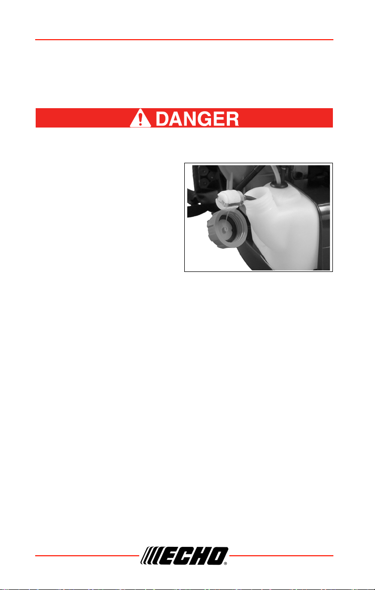
◆ Fuel tanks/cans may be under pressure. Always loosen
fuel caps slowly allowing pressure to equalize.
◆ NEVER refuel a unit when the engine is HOT or RUNNING!
◆ DO NOT fill fuel tanks indoors. ALWAYS fill fuel tanks
outdoors over bare ground.
◆ DO NOT overfill fuel tank. Wipe up spills immediately.
◆ Securely tighten fuel tank cap and close fuel container
after refueling.
◆ Inspect for fuel leakage. If fuel leakage is found, do not
start or operate unit until leakage is repaired.
◆ Move at least 3 m (10 ft.) from refueling location before
starting the engine.
Gasoline vapor is heavier than air, and can travel along the
ground to nearby sources of ignition such as electrical motors,
pilot lights, and hot or running engines. Vapors ignited by an
ignition source can flash back to the fuel container, resulting in
an explosion, fire, serious or fatal injuries, and extensive
property damage.

OPERATION PB-580 H/T
26 X7505200707
© 07/19 ECHO Incorporated
Mixing Instructions
1. Fill an approved fuel container
with half of the required
amount of gasoline.
2. Add the proper amount of
2-stroke oil to gasoline.
3. Close container and shake to
mix oil with gasoline.
4. Add remaining gasoline, close
fuel container, and remix.
Spilled fuel is a leading cause of hydrocarbon emissions. Some
states may require the use of automatic fuel shut-off containers to
reduce fuel spillage.
Storage - Fuel storage laws vary by locality. Contact your local government
for the laws affecting your area. As a precaution, store fuel in an approved,
airtight container. Store in a well-ventilated, unoccupied building, away from
sparks and flames.
• Empty the fuel tank prior to storing the unit. Return unused fuel to an
approved fuel storage container.
Stored fuel ages. Do not mix more fuel than you expect to use in 30
days, 90 days when a fuel stabilizer is added.
Stored two-stroke fuel may separate. ALWAYS shake fuel container
thoroughly before each use.
Used oil and gasoline, and soiled towels are hazardous waste
materials. Disposal laws vary by locality.
Fuel to Oil Mix – 50:1 Ratio
US Metric
Gas Oil Gas Oil
gal. fl.oz. L cc
12.65100
2 5.2 10 200
51325500
PB-580 H/T OPERATION
X7505200707 27
© 07/19 ECHO Incorporated
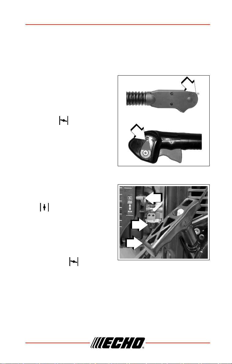
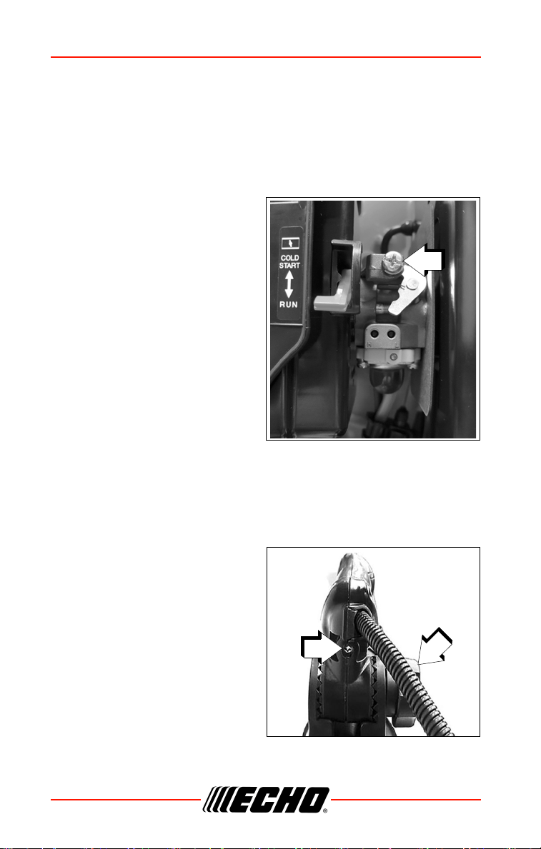
Starting Cold Engine
• Recoil starter: Use short pulls - only 1/2- 2/3 of rope length for starting.
Do not allow the rope to snap back in. Always hold the unit firmly.
• (PB-580H): Rotate spring loaded throttle arm downward to a comfortable
operating position.
1.
Throttle Lever
Move throttle lever (A) to IDLE
position.
2.
Choke
Move choke (B) UP to COLD
START ( ) position.
3.
Purge Bulb
Pump purge bulb (C) until fuel is
visible. Pump bulb an additional
4 or 5 times.
4.
Recoil Starter
Pull recoil starter handle (D) until
engine fires, or a maximum of 5 pulls
5.
Choke
After engine fires (or 5 pulls),
move choke lever back to RUN
( ) position, then pull starter
handle/rope until engine starts
and runs. Allow unit to warm up
at idle for several minutes.
Note: If engine does not start
with choke in “RUN”
position after 5 pulls,
move choke to COLD
START ( ) position,
and repeat steps 3- 5.
6.
Throttle Lever
Allow engine to warm up for several minutes before use.
7. Throttle Lever
After engine warm-up, move throttle lever gradually to increase engine
RPM to desired operating speed.
A
A
PB-580 H
PB-580 T
B
C
D
OPERATION PB-580 H/T
28 X7505200707
© 07/19 ECHO Incorporated
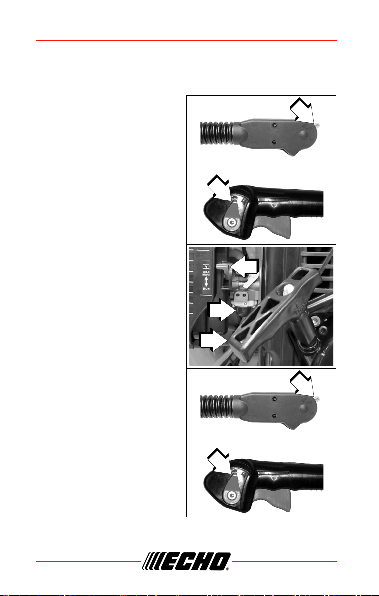
Starting Warm Engine
The starting procedure is the same as Cold Start except DO NOT close the
choke.v
1.
Throttle Lever
Move throttle lever (A) to IDLE
position.
2.
Purge Bulb
Pump purge bulb (C) until fuel is
visible. Pump bulb an additional
4 or 5 times.
3.
Recoil Starter
Pull recoil starter handle (D) and
engine should start. Do not use
choke (B)
Note: If engine does not start
after 5 pulls, use cold
start procedures.
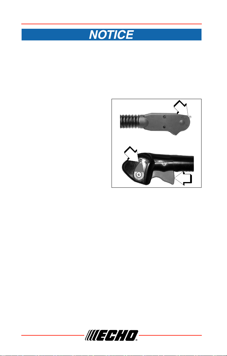
Stopping Engine
- PB-580 H
1.
Throttle Lever
Move throttle lever (A) to IDLE
position and allow engine to
return to idle before shutting off
engine.
2.
Throttle Lever
Move throttle lever (A) to “O“
(STOP) position.
A
A
PB-580 H
PB-580 T
B
C
D
A
A
PB-580 H
PB-580 T

PB-580 H/T OPERATION
X7505200707 29
© 07/19 ECHO Incorporated
- PB-580 T
1. Throttle Lever
Release throttle trigger. Move Throttle Lever (A) forward to idle position
and allow engine to return to idle before shutting off engine.
2.
Throttle Lever
Move Throttle Lever (A) all the way forward to STOP position.
If engine does not stop when stop switch is moved to STOP
position, close choke - COLD START position - to stall engine.
Have your dealer repair stop switch before using unit again.
Operating Blower
Engine exhaust IS HOT, and contains Carbon Monoxide (CO), a
poison gas. Breathing CO can cause unconsciousness, serious
injury, or death. Exhaust can cause serious burns. ALWAYS
position unit so that exhaust is directed away from your face
and body.
Always wear safety glasses, hearing protection and a face filter
mask or serious personal injury may result. Do not point the
blower pipe in the direction of people or pets.
Use reduced speed only when performing light-duty tasks or to
comply with local noise regulations. Continuous low speed operation
may allow fuel/oil residue to build-up on the piston and cause rapid
build-up of carbon on the spark arrestor screen, resulting in
overheating and engine damage. To reduce harmful build-up, run
engine at wide open throttle for at least 5 minutes every hour, and
inspect/clean the spark arrestor screen after approximately 40 hours
of operation.
Read the Safety Section carefully.
OPERATION PB-580 H/T
30 X7505200707
© 07/19 ECHO Incorporated
To avoid engine damage due to over-revving, do not block blower
pipe.
1. Use only during appropriate hours. Contact your local government for
the ordinances affecting your area.
2. To reduce sound levels, limit the number of pieces of equipment used at
any one time.
3. Allow the engine to warm up at a fast idle for a few minutes.
4. PB-580 H
Set engine speed with throttle
lever (A).
PB-580 T
Control engine speed with
throttle trigger (B), or for
continuous use, set engine
speed with throttle lever (A).
5. Use lower speed to blow dry
leaves from walks, patios and
drives. Use rakes and brooms
to loosen debris before blowing.
6. Additional speed may be
necessary to clean grass and leaves from a lawn or flower bed.
7. Higher speed may be necessary to move gravel, dirt, snow, bottles or
cans from a driveway, street, parking lot or stadium.
8. Always stop unit using stop engine procedure.
Note: Never use a higher speed setting than necessary to perform a
task. Remember, the higher the engine speed, the louder the
blower noise.
9. Minimize dust by using blower at lower speeds or dampen surface with
water. Blower can be used to clean most surfaces when water
conservation is desired.
10. Use the full blower pipe configuration when blowing.
11. After using blowers and other equipment, CLEAN UP! Dispose of
debris in trash receptacles.
A
A
PB-580 H
PB-580 T
B
PB-580 H/T OPERATION
X7505200707 31
© 07/19 ECHO Incorporated
Contacting blower pipe tip on abrasive surfaces can create
sharp cutting edges and can result in personal injury if touched.
Do not scrape or drag blower pipe tip when operating or
transporting unit. Replace blower pipe assembly if protective
metal ring is worn, cracked or deformed.
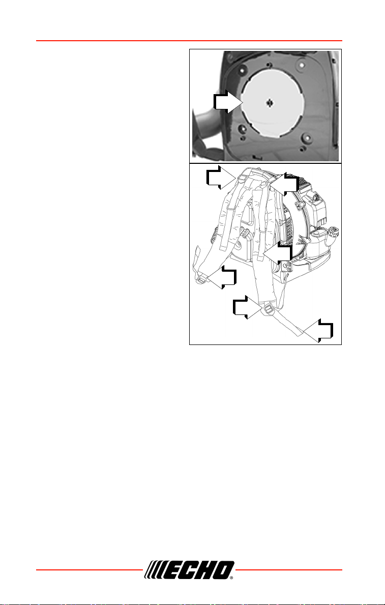
Cold Weather Operation
Plug
For operation in cold weather, install
plug in cold weather position (C),
otherwise icing can occur.
For operation in normal weather,
install plug in warm weather position
(D), otherwise over heating can
occur.
Intake Cover (optional)
In cold weather, intake cover can be
installed for operator comfort. Intake
cover is not included.
1. Remove back cushion (A) from
frame.
C
D
A
OPERATION PB-580 H/T
32 X7505200707
© 07/19 ECHO Incorporated
2. Install intake cover (B) on frame
over air intake.
3. Install back cushion (A) to
frame over intake cover.
Note: Blower performance may
be reduced slightly.
Adjust the Harness
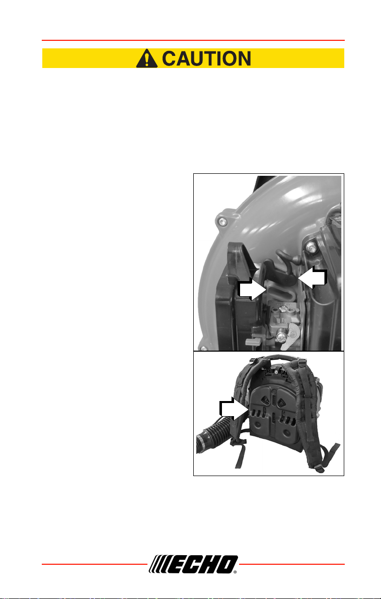
1. Loosen upper and lower
buckles (A), then put blower on
your back.
2. Pull strap (B) downward to
adjust position of blower.
3. Pull (C) to adjust angle
between your back and the
blower.
B
A
A
A
A
B
C

PB-580 H/T MAINTENANCE
X7505200707 33
© 07/19 ECHO Incorporated
MAINTENANCE
Moving parts can amputate fingers or cause severe injuries.
Keep hands, clothing and loose objects away from all openings.
Always stop engine, disconnect spark plug, and make sure all
moving parts have come to a complete stop before removing
obstructions, clearing debris, or servicing unit. Allow unit to
cool before performing service. Wear gloves to protect hands
from sharp edges and hot surfaces.
Operating a poorly maintained unit can result in serious injuries
to operator or bystanders. Always follow all maintenance
instructions as written, otherwise serious personal injury may
result.
Your unit is designed to provide many hours of trouble free service. Regular
scheduled maintenance will help your unit achieve that goal. If you are
unsure or are not equipped with the necessary tools, we recommend that
you take your unit to a Servicing Dealer for maintenance. To help you decide
whether you want to DO-IT-YOURSELF or have the Dealer do it, each
maintenance task has been graded. If the task is not listed, see your Dealer
for repairs.
Skill Levels
Level 1 = Easy to do. Common tools may be required.
Level 2 = Moderate difficulty. Some specialized tools may be required.
Level 3 = See your dealer.
Click HERE or go to http://www.echo-usa.com/products/maintenance-kit
or
HERE https://www.shindaiwa-usa.com/you-can.aspx
For information about maintenance kits.

MAINTENANCE PB-580 H/T
34 X7505200707
© 07/19 ECHO Incorporated
Maintenance Intervals
IMPORTANT NOTE - Time intervals shown are maximum. Actual use and
your experience will determine the frequency of required maintenance.
MAINTENANCE PROCEDURE NOTES:
1.
Replacement is recommended based on the finding of damage or wear
during inspection.
COMPONENT/SYSTEM MAINTENANCE PROCEDURE
SKILL
LEVEL
Daily or Before Use
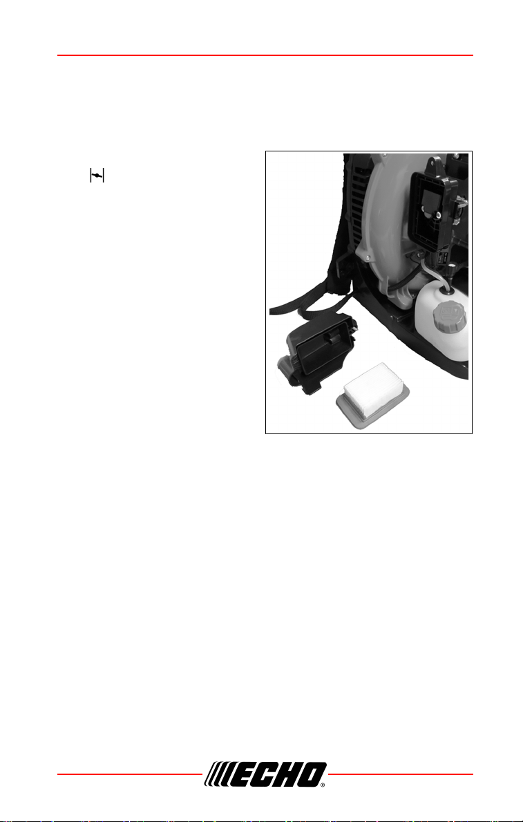
Air Filter
Inspect/Clean
1
1
Choke Shutter
Fuel System
Inspect
Cooling System
Inspect/Clean 2
Recoil Starter Rope
Inspect/Clean 1
1
Screws/Nuts/Bolts
Inspect/Tighten/Replace
1
Every Refuel
Fuel System
Inspect 1 1
Cooling System Inspect/Clean 2
3 Months
Air Filter
Replace
1
1
Fuel Filter
Inspect
1
Fuel Cap Gasket
Spark Plug
Inspect/Clean/Replace 1
Muffler Spark Arrestor
2
Cylinder Exhaust Port
Inspect/Clean/De-carbon
Yearly
Fuel Filter
Inspect/Replace1
1
Fuel Cap Gasket
Replace 1
PB-580 H/T MAINTENANCE
X7505200707 35
© 07/19 ECHO Incorporated
Air Filter
Level 1.
1. CLOSE choke (COLD START
[ ] position). This prevents
dirt from entering the carburetor
throat when the air filter is
removed. Brush accumulated
dirt from air cleaner area.
2. Remove air filter cover. Brush
dirt from inside cover.
3. Remove air filter and lightly
brush debris from filter.
Replace filter if it is damaged,
fuel soaked, very dirty, or the
rubber sealing edges are
deformed.
4. If filter can be reused, be
certain it:
• Fits tightly in the air filter cavity
• Is installed with the original
side out
5. Install air filter cover.
Parts Required: Tune Up Kit.
MAINTENANCE PB-580 H/T
36 X7505200707
© 07/19 ECHO Incorporated
Fuel Filter
Level 1.
Fuel is VERY flammable. Use extreme care when mixing,
storing or handling, or serious personal injury may result.
1. Use a clean rag to remove
loose dirt from around fuel cap
and empty fuel tank.
2. Pull the fuel line and filter from
the tank.
3. Remove the filter from the line
and install the new filter.
Note: Federal EPA regulations
require all model year
2012 and later gasoline
powered engines
produced for sale in the United States to be equipped with a
special low permeation fuel supply hose between the
carburetor and fuel tank. When servicing model year 2012
and later equipment, only fuel supply hoses certified by EPA
can be used to replace the original equipment supply hose.
Fines up to $37,500 may be enforced for using an un-certified
replacement part.
Parts Required: Tune Up Kit.
PB-580 H/T MAINTENANCE
X7505200707 37
© 07/19 ECHO Incorporated
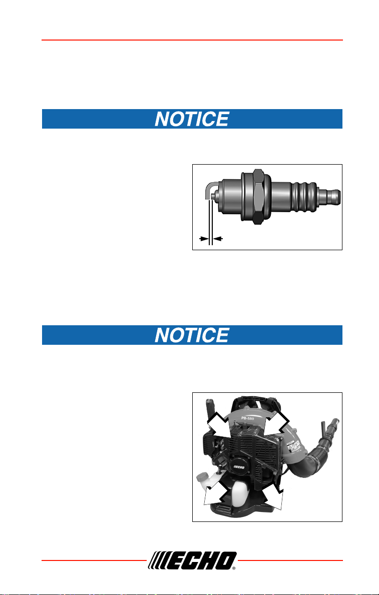
Spark Plug
Level 2.
Use only NGK BPM8Y spark plug (BPMR8Y in Canada) otherwise
severe engine damage may occur.
1. Remove spark plug and check
for fouling, worn and rounded
center electrode.
2. Clean the plug or replace with a
new one. DO NOT sand blast to
clean. Remaining sand will
damage engine.
3. Adjust spark plug gap by
bending outer electrode.
4. Tighten spark plug to 150-170 kgf • cm (130-150 in • lbf).
Cooling System
Level 2.
To maintain proper engine operating temperatures, cooling air must
pass freely through the cylinder fin area. This flow of air carries
combustion heat away from the engine.
Overheating and engine seizure can
occur when:
• Air intakes are blocked,
preventing cooling air from
reaching the cylinder.
• Dust and grass build up on the
outside of the cylinder. This build
up insulates the engine and
prevents the heat from leaving.
Parts Required: Tune Up Kit.
0.65 mm (0.026 in.)
MAINTENANCE PB-580 H/T
38 X7505200707
© 07/19 ECHO Incorporated
Removal of cooling passage blockages or cleaning of cooling fins is
considered “Normal Maintenance.” Any failure attributed to lack of
maintenance is not warranted.
Cleaning Grill
1. Brush accumulated debris from intake grill between backpack frame
and blower housing.
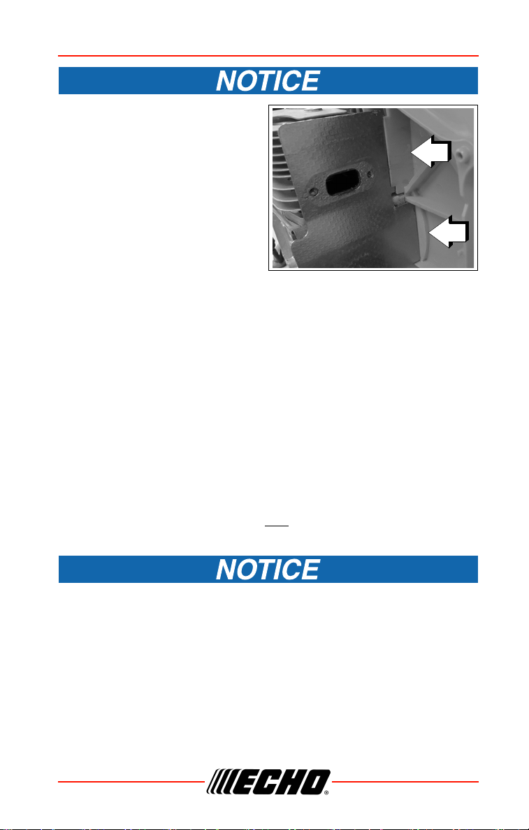
Cleaning Cylinder Fins
1. Remove spark plug.
2. Remove starter
3. Remove engine cover.
4. Clean cylinder fins (A) to allow
cooling air to pass freely
5. Assemble components in
reverse order.
A
PB-580 H/T MAINTENANCE
X7505200707 39
© 07/19 ECHO Incorporated
Exhaust System
Spark Arrestor Screen
Level 2.
Carbon deposits in muffler will cause a drop in engine output and
overheating. Spark arrestor screen must be checked periodically.
1. Remove spark plug.
2. Remove starter.
3. Remove engine cover.
4. Place piston at Top Dead Center (TDC) to prevent carbon/dirt from
entering cylinder.
5. Remove spark arrestor cover
(A), gasket (B) and spark
arrestor screen (C) from
muffler.
6. Clean carbon deposits from
muffler components.
Note: When cleaning carbon
deposits, be careful not to
damage the catalytic
element inside muffler.
7. Replace screen if it is cracked,
plugged, or has holes burned
through.
8. Replace gasket.
9. Assemble components in reverse order.
Parts Required: Spark Arrestor Screen, Gasket
A
B
C
MAINTENANCE PB-580 H/T
40 X7505200707
© 07/19 ECHO Incorporated
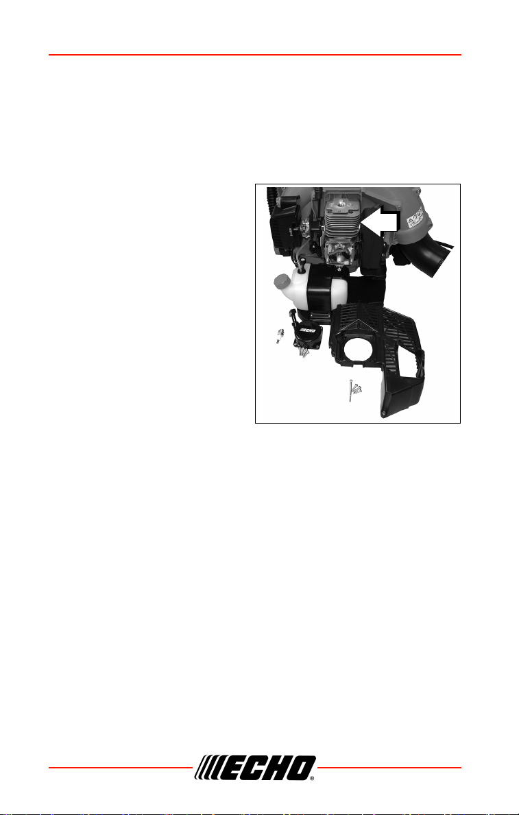
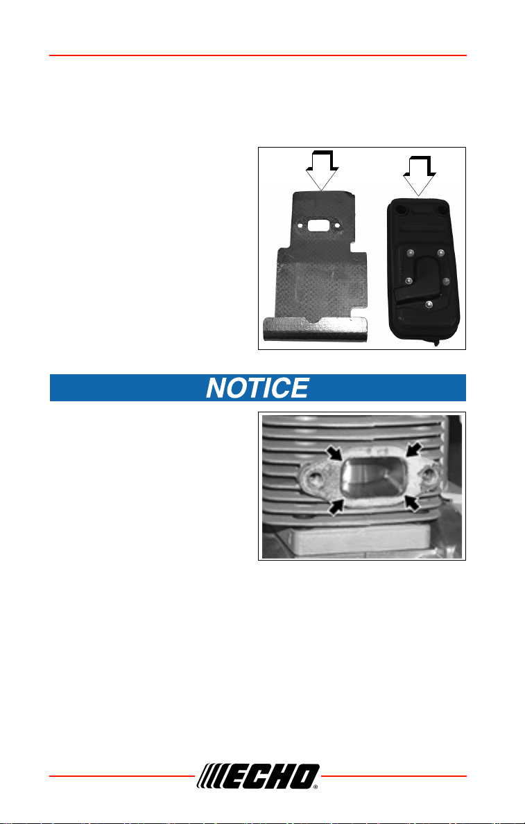
Exhaust Port Cleaning
Level 2.
1. Remove spark plug.
2. Remove starter
3. Remove engine cover.
4. Place piston at top dead center.
Remove muffler (A) heat shield
(B).
5. Use a wood or plastic scraping
tool to clean deposits from
cylinder exhaust port.
Never use a metal tool to scrape
carbon from the exhaust port. Do
not scratch the cylinder or piston
when cleaning the exhaust port.
Do not allow carbon particles to
enter the cylinder.
6. Replace heat shield.
Parts Required: Heat Shield
A
B
PB-580 H/T MAINTENANCE
X7505200707 41
© 07/19 ECHO Incorporated
Assure heat shield is installed
correctly behind rib (A) and in
front of rib (B) in fan case.
7. Install muffler.
8. Tighten muffler mounting bolts
(or nuts) to 90-110 kgf • cm
(80-95 in • lbf).
9. Assemble components in
reverse order.
10. Start engine, and warm to
operating temperature.
11. Stop engine, and re-tighten mounting bolts (or nuts) to specifications.
Carburetor Adjustment
Engine Break-In
New engines must be operated a minimum duration of two tanks of fuel
break-in before carburetor adjustments can be made. During the break-in
period your engine performance will increase and exhaust emissions will
stabilize. Idle speed can be adjusted as required.
High Altitude Operation
This engine has been factory adjusted to maintain satisfactory starting,
emission, and durability performance up to 1,100 feet above sea level (ASL)
(96.0 kPa). To maintain proper engine operation and emission compliance
above 1,100 feet ASL the carburetor may
need to be adjusted by an
authorized service dealer.
If the engine is adjusted for operation above 1,100 feet ASL, the
carburetor must be re-adjusted when operating the engine below
1,100 feet ASL, otherwise severe engine damage may result.
Level 2.
Note: Every unit is run at the factory and the carburetor is set in
compliance with emission regulations. Carburetor
adjustments, other than idle speed, must be performed by an
authorized dealer.
A
B
MAINTENANCE PB-580 H/T
42 X7505200707
© 07/19 ECHO Incorporated
Idle Adjustment
Before adjustment make sure that:
• Air filter is clean and properly installed.
• Spark arrestor screen and muffler are free of carbon.
• Blower pipes are installed.
1. Start engine, run at idle for one
minute.
2. Complete warm up by running
at full throttle for 5 minutes,
operating choke twice to clear
air from carburetor chambers.
3. Check idle speed and reset if
necessary. If a tachometer is
available, idle speed screw (A)
should be set to the
specifications found on
“Specifications” Page of this
manual. Turn idle screw (A)
clockwise to increase idle
speed; counter clockwise to
decrease idle speed.
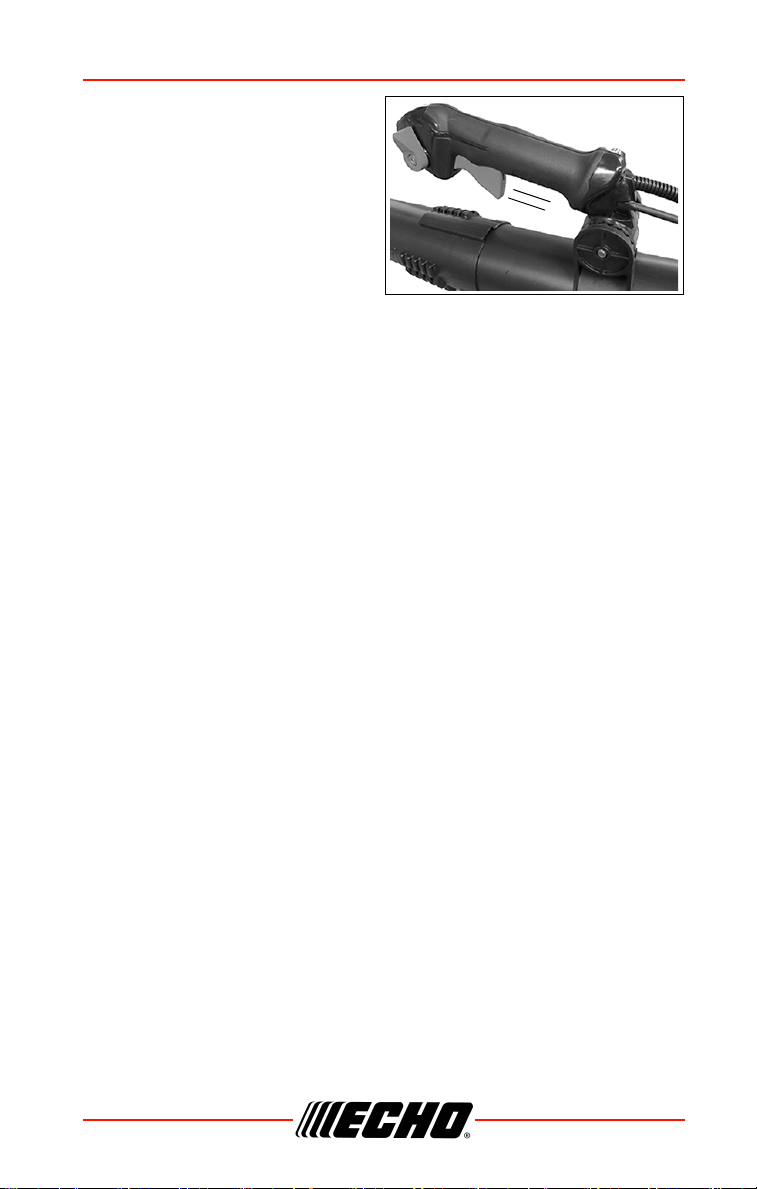
Throttle Cable Adjustment
Level 1
If engine idle speed changes when blower pipe is moved, or engine will not
reach full wide open throttle speed, adjust throttle cable.
1. Loosen handle adjustment
knob (C) and tilt Tube Throttle
handle forward to expose
Adjustment Screw (D).
A
D
C
PB-580 H/T MAINTENANCE
X7505200707 43
© 07/19 ECHO Incorporated
2. Turn Adjustment Screw until
Throttle Trigger free play is
4 - 6 mm (3/16-1/4 in.).
3. After adjustment, squeeze and
release Throttle Trigger several
times to verify Carburetor
Throttle Shaft has full range of
movement from idle to wide
open throttle positions.
4-6 mm

TROUBLESHOOTING PB-580 H/T
44 X7505200707
© 07/19 ECHO Incorporated
TROUBLESHOOTING
Fuel vapors are extremely flammable and may cause fire and/or
explosion. Never test for ignition spark by grounding spark plug
near cylinder plug hole, otherwise serious personal injury may
result.
ENGINE PROBLEM TROUBLESHOOTING CHART
Problem Check Status Cause Remedy
Engine
starts
hard
or Engine
does not
start
Fuel at
carburetor
No fuel at
carburetor
Fuel strainer or
fuel line
obstructed
Clean or replace
See your dealer
Engine
starts
hard
or
Engine
does not
start
Fuel at
cylinder
No fuel at
cylinder
Carburetor See your dealer
Muffler wet
with fuel
Fuel mixture
too rich
OPEN choke
Clean or replace
air filter
Adjust carburetor
See your dealer
Spark at
end of plug
wire
No spark
Ignition at
STOP position
Electrical prob-
lem
Interlock switch
Move ignition
away from STOP
position.
See your dealer
Spark at
plug
Incorrect gap -
Covered with
carbon -
Fouled with
fuel - Plug
defective
Adjust to
0.65mm (0.026
in.)
Clean or replace
plug

PB-580 H/T TROUBLESHOOTING
X7505200707 45
© 07/19 ECHO Incorporated
Engine
runs, but
dies
or
Engine
does not
acceler-
ate
properly
Air filter Air filter dirty Normal wear Clean or replace
Fuel filter
Fuel filter
dirty
Contaminants
or residue in
fuel
Replace filter or
replace fuel
Fuel vent
Fuel vent
plugged
Contaminated
fuel
Clean or replace
Spark plug
Plug dirty or
worn
Normal wear
Clean and adjust
or replace
Carburetor
Improper
adjustment
Vibration Adjust
Cooling
system
Cooling
system dirty
or plugged
Extended oper-
ation in dirty or
dusty locations
Clean
Spark
arrestor
screen
Spark arres-
tor screen
plugged
Normal wear Replace
Engine
does not
crank
N/A
Internal engine
problem
See your dealer
ENGINE PROBLEM TROUBLESHOOTING CHART
Problem Check Status Cause Remedy

STORAGE PB-580 H/T
46 X7505200707
© 07/19 ECHO Incorporated
STORAGE
During operation the muffler or catalytic muffler and
surrounding cover become hot. Always keep exhaust area clear
of flammable debris during transportation or when storing,
otherwise serious property damage or personal injury may
result.
Long Term Storage (Over 30 Days)
Do not store your unit for a prolonged period of time (30 days or longer)
without performing protective storage maintenance which includes the
following:
1. Store unit in a dry, dust free place, out of the reach of children.
Do not store in enclosure where fuel fumes may accumulate or
reach an open flame or spark.
2. Place the stop switch or lever in the “OFF” position.
3. Remove accumulation of grease, oil, dirt and debris from exterior of
unit.
4. Perform all periodic lubrication and services that are required.
5. Tighten all the screws and nuts.
6. Drain fuel tank completely. Press purge bulb 6 -7 times to remove
remaining fuel from carburetor then drain the tank again. Close choke,
start and run the engine until it stops due to lack of fuel.
7. Allow engine to cool. Remove the spark plug lead from the spark plug.
Remove the spark plug. Pour 7 cc (0.25 oz.) of fresh, clean, two-stroke
engine oil into the cylinder through the spark plug hole.
8. Pull the recoil starter handle 2-3 times to distribute the oil inside the
engine.
9. Observe the piston location through the spark plug hole. Pull the recoil
handle slowly until the piston reaches the top of its travel and leave it
there.
10. Install the spark plug. Connect the spark plug lead to the spark plug.
11. Remove blower pipe assembly from unit.

PB-580 H/T SPECIFICATIONS
X7505200707 47
© 07/19 ECHO Incorporated
SPECIFICATIONS
MODEL PB-580 H PB-580 T
Length (w/o pipes) 379 mm (14.92in.) 379 mm (14.92 in.)
Width (w/o pipes) 537 mm (21.14 in.) 478 mm (18.82 in.)
Height (w/o pipes) 459 mm (18.07 in.)
Weight (dry) (w/o pipes) 9.4 kg (20.7 lb.) 9.3 kg (20.5 lb.)
Engine Type
Air cooled, two-stroke, single cylinder gasoline
engine
Bore 46.0 mm (1.81 in.)
Stroke 35.0 mm (1.38 in.)
Displacement 58.2 cc (3.55 cu. in.)
Exhaust
Spark arrestor muffler or spark arrestor muffler
with catalyst
Carburetor Diaphragm w/purge pump
Ignition System
Flywheel magneto, capacitor discharge
ignition type
Spark Plug
NGK BPM8Y (
NGK BPMR8Y in Canada) (Gap
0.65 mm [0.026 in.])
Fuel Mixed (Gasoline and Two-stroke Oil)
Gasoline/Oil Ratio 50:1
Gasoline
Use 89 Octane unleaded. Do not use fuel
containing methyl alcohol, more than 10%
ethyl alcohol or 15% MTBE. Do not use
alternative fuels such as E-15 or E-85.
Oil
ISO-L-EGD (ISO/CD 13738) and J.A.S.O.
M345- FD
, two-stroke, air-cooled engine oil.
Fuel Tank Capacity 1.83 L (62 US fl. oz.)
Starter System Automatic Recoil Starter, centrifugal type
Idle Speed 2,700 RPM
Wide Open Throttle
Speed (W.O.T.)
6,550 RPM
Average Air Speed w/
pipes
80.5 m/sec (180mph)
Maximum Air Speed w/
pipes
96.4 m/sec (216 mph)
Air Volume 14.7 m
3
/min. (5107 ft.
3
/min.)

SPECIFICATIONS PB-580 H/T
48 X7505200707
© 07/19 ECHO Incorporated
Sound Level at 50 ft.
dB(A) scale per ANSI
B175.2
70 dB(A)
MODEL PB-580 H PB-580 T

PB-580 H/T PRODUCT REGISTRATION
X7505200707 49
© 07/19 ECHO Incorporated
PRODUCT REGISTRATION
Thank you for choosing ECHO Power Equipment
Please go to http://www.echo-usa.com/Warranty/Register-Your-ECHO
to
register your new product on-line. It's FAST and EASY! NOTE: your
information will never be sold or misused by ECHO, Inc. Registering your
purchase enables us to contact you in the unlikely event of a service update
or product recall, and verifies your ownership for warranty consideration.
If you do not have access to the Internet, you can complete the form below
and mail to:
ECHO Inc., Product Registration, PO Box 1139, Lake Zurich IL 60047.
PRODUCT REGISTRATION PB-580 H/T
50 X7505200707
© 07/19 ECHO Incorporated

PB-580 H/T NOTES
X7505200707 51
© 07/19 ECHO Incorporated
NOTES