
Handheld LCR Meter
User’s Manual
V1.0.2

I
Content
Safety ........................................................................................................................................ 1
Safety Guidelines ...................................................................................................................... 1
Safety Symbols ......................................................................................................................... 1
Introduction ............................................................................................................................... 3
Chapter 1 Overview of front panel ............................................................................................ 4
1.1 Front panel .................................................................................................................. 4
1.2 User’s Interface ........................................................................................................... 6
1.2.1 Measurement Interface ..................................................................................... 6
1.2.2 System settings interface .................................................................................. 6
1.3 Test port ....................................................................................................................... 7
Chapter 2 Operation instruction................................................................................................ 8
2.1 Startup and shutdown ................................................................................................. 8
2.2 Test parameter ............................................................................................................. 8
2.2.1 Test frequency ................................................................................................... 8
2.2.2 Test level ........................................................................................................... 8
2.2.3 Test range .......................................................................................................... 9
2.2.4 Test speed ......................................................................................................... 9
2.2.5 Main parameters ............................................................................................... 9
2.2.6 Secondary parameters ...................................................................................... 9
2.2.7 Set nominal value of tolerance mode ............................................................... 9
2.2.8 Equivalent mode ............................................................................................. 10
2.3 Relative mode ............................................................................................................ 10
2.4 Reading hold mode (HOLD) ...................................................................................... 10
2.5 Data recording function ............................................................................................. 11
2.6 Correction function .................................................................................................... 11
2.7 Firmware Update ....................................................................................................... 12
Chapter 3 Quick application guide ......................................................................................... 14
3.1 Resistance measurement.......................................................................................... 15
3.2 Capacitance measurement ....................................................................................... 16
3.3 Inductance measurement .......................................................................................... 16
3.4 Impedance measurement ......................................................................................... 17
Chapter 4 Telecommunication ................................................................................................ 18
4.1 Connect the instrument to PC ................................................................................... 18
4.2 Command Reference ................................................................................................ 20
4.2.1 Public command .............................................................................................. 20
4.2.2 Subsystem commands .................................................................................... 20
Chapter 5 Specification........................................................................................................... 23
5.1 General Specification ................................................................................................ 23
5.2 Accuracy .................................................................................................................... 23
Chapter 6 Maintenance .......................................................................................................... 28
6.1 Service ....................................................................................................................... 28
6.2 Clean ......................................................................................................................... 28
Accessories ............................................................................................................................. 29

1
Safety
Review the following safety precautions carefully before operate the device to avoid any
personal injuries or damages to the device and any products connected to it. To avoid potential
hazards use the device as specified by this user’s guide only.
⚫ Only professionally authorized personnel can perform maintenance.
⚫ Do not run the product when the outer cover or panel is open.
⚫ Do not operate with suspected failures. If suspected damage occurs with the device, have
it inspected by qualified service personnel before further operations.
⚫ Do not operate in wet/damp conditions.
⚫ Do not use in explosive environments
⚫ Keep product surfaces clean and dry.
⚫ Security warning: One should abide by the relevant terms in the manual regarding safety or
injury to human body or damages to the product, as well as operation or environment which
may result in test failure.
Safety Guidelines
To make sure safe use of equipment, follow these guidelines:
⚫ The instrument is suitable for indoor use and an altitude of less than 2,000 meters. In case of
short-term outdoor use, prevent it from direct sunlight, water, electromagnetic radiation, dust,
etc.
⚫ Before the use, please read and understand the warning and safety information mentioned in
this manual.
⚫ Use the instrument according to the function specified in the manual.
⚫ If the component needs measurement, make sure the circuit is turned off and all capacitors in
the circuit are discharged before the measurement.
⚫ Before the measurement, components such as capacitors shall be discharged.
⚫ The lithium battery of 18650 or Type C-USB is used to provide power for the instrument. It
can be charged with Type C-USB port.
Safety Symbols
Warning: Remind the user to follow the operating procedures in the manual.

2
Environment
⚫ Please do not operate the instrument in the place that is dusty, vibrative, under direct sunlight
or where there is corrosive air.
⚫ The normal working temperature is 0℃~40℃, relative humidity ≤75%, so the instrument
should be used under above condition to guarantee the accuracy.
⚫ Please store the instrument in the place where temperature is between 5℃ and 40℃,
humidity is less than 85%RH. If the instrument will not be put in use for a time, please have it
properly packed with its original box or a similar box for storing.
⚫ The instrument, especially the test cable should be far from strong electro-magnetic field, to
avoid the jamming on measurement.
Use of Test Fixture
Please use the accessory test fixture or cable together with your device. The test fixture made by
user or from other company may cause the incorrect measurement result. The test fixture, cable
and the pin of DUT should be kept clean, thus to guarantee the good connection between DUT
and fixture.
Warm-up
⚫ To guarantee the accurate measurement, the warm-up time is no less than 15min.
⚫ Please not turn on or off instrument frequently, in order to avoid the inner data fluster.
General Check
When you have got a new LCR, it is suggested that you should perform a general inspection on
the instrument according to the following steps:
⚫ Check the shipping container for damage:
Inspect the shipping container for damage after unpacking it. It is not recommended to power on
the instrument in the case of a damaged container.
⚫ Check the accessories:
Accessories supplied with the instrument are listed in “Accessories” in this manual. If the contents
are incomplete or damaged, please notify our distributor at your local area or the sales
department.
⚫ Check the instrument:
In case there is any mechanical damage or defect, or the instrument does not operate properly,
please notify our distributor at your local area or the sales department.

3
Introduction
This handheld LCR meter is used to measure inductance, capacitance, resistance and other
components of the parameters, small size, using 7.4V lithium battery power supply, can be
applied to desktop applications, more mobile measurement and handheld measurement
occasions to provide great convenience.
It provides a resolution of four thousands digits for main parameters and a resolution of 0.0001 for
secondary parameter. The highest measurement frequency is 100kHz, and can measure the level
of 0.6Vrms, 0.3Vrms. Its automatic range can display the results in the fast, medium, or slow
mode. It can automatically select the appropriate measurement parameters according to the
characteristics of the component. The measurement accuracy can reach 0.25%. It combines the
convenience of a handheld instrument and good performance of a table-type one.
The operation is simple and intuitive, and the test frequency, parameters and speed can be
selected immediately. It also has a recording mode to assist in reading data. Open circuit and
short circuit correction function to improve the accuracy of measurement. Practical configuration
menu can set buzzer, automatic shutdown, language and other operations.
The instrument is equipped with remote communication function and can be connected to PC via
Type C-USB cable for remote control and data acquisition.
4
Chapter 1 Overview of front panel
1.1 Front panel
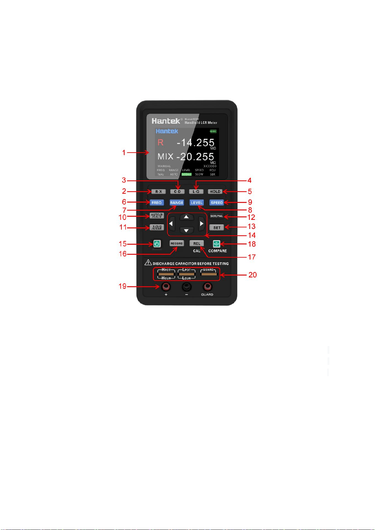
Description of the front panel is shown in the figure (Note: In this manual, long press means
holding the key for more than 2 seconds).
1. Display: 2.8 inch TFT LCD screen, which display all functions of the instrument.
2. R-X shortcut key: Select the main parameter as R and the secondary parameter as X directly.
3. C-D shortcut key: Select the main parameter as C and the secondary parameter as D directly.
4. L-Q shortcut key: Select the main parameter as L and the secondary parameter as Q directly.
5. Data holding recording key: Turn on or off the data holding function.
6. Frequency key: Switch to fixed frequency quickly.
7. Range key: Switch to the required range quickly. You can select Auto, 10Ω, 100Ω, 1kΩ, 10kΩ
and 100kΩ in turn. Auto is the automatic range, LCR will automatically select the appropriate
hardware range according to the current tested component, and the other ranges are the fixed
gear position.
8. Level shortcut key: Switch to the fixed level (300mV, 600mV RMS) quickly.
9. Measuring speed key: Switch to the required measurement speed (Fast, Medium and Slow).

5
10. Main parameter key: Switch to the main parameters quickly. You can select Auto, R, L, C, Z
in turn. Auto is the function of automatic parameters. LCR selects the appropriate combination of
main parameters and secondary parameters according to the properties of the current tested
component.
11. Secondary parameter key: Switch to the secondary parameters quickly. If the main
parameter select as Auto, this key will not work.
12. Equivalent mode key: Switch equivalent between SER and PAL quickly. User should select
the equivalent mode according to test need.
13. Set key: Press the key to enter the setting interface to set the system language, automatic
shutdown, display brightness, boot state and buzzer. Click again the key in the setting interface to
view the device system information. Click again it to return to the test interface.
14. Arrow keys: left and right arrow keys to control the movement of the cursor; up and down
arrow keys to select the parameter.
15. Power key: Press it to turn on or off the instrument.
16. Data holding recording key: Press to turn on or off the data holding function. Press the key
successively can switch functions of MAX, MIN and AVG in turn, and return to normal test
interface after completing one cycle. If you change the main or secondary parameter, it will exit
this function. The function is disabled in automatic parameters.
17. Relative and correction multifunctional key: Short press to turn on or off the relative
function, short press again to exit the relative value (REL) function. Long press to turn on the
correction function.
18. Comparator switch and tolerance limits shortcut multifunctional key: Long press to
turn on or off the comparator. Short press to quickly switch deviation tolerance limit.
19. 3-terminal test jack
20. 5-terminal test notch
Note: Please see the label on the adapter for its input parameters; use the supplied
adapter, or purchase the specified power adapter from our company. The use of other
adapters may cause unnecessary damage.
Reminder: After connect the external power supply, the internal battery power supply
circuit will be automatically cut off and charge the battery,
the LCR
has an independent
charging management controller, even when the instrument is turned off, the charging
control still works normally.
6
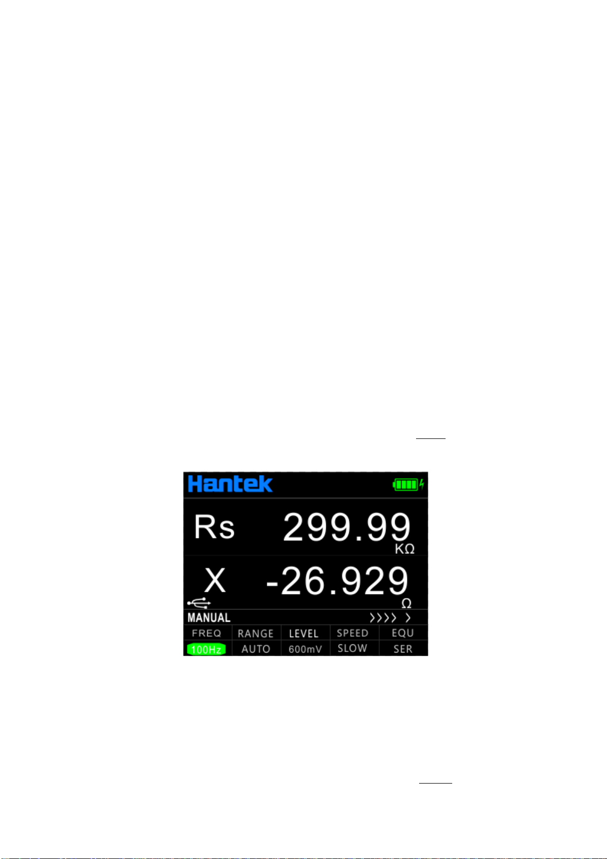
1.2 User’s Interface
1.2.1 Measurement Interface
1. Main parameter display
2. Secondary parameter display
3. ’HOLD’ indicates the data holding state.
4. USB connection state, displayed when it is connected to the PC and hidden at any
other time;
When connected the instrument to the computer in the initial, the USB icon is white, which
means that the USB is connected. At this time, the key is still available and unlocked. After
receiving the first effective command, the USB icon becomes green, which means that the
computer is communicated with the instrument successfully. The front panel button is unlocked
after USB is pulled out or *GTL command is used. Then the USB icon turns white again and the
button is available.
5. Measurement parameter settings
6. Battery power icon: The remaining power is indicated. Please timely charge the instrument
when the power is insufficient.
1.2.2 System settings interface
7
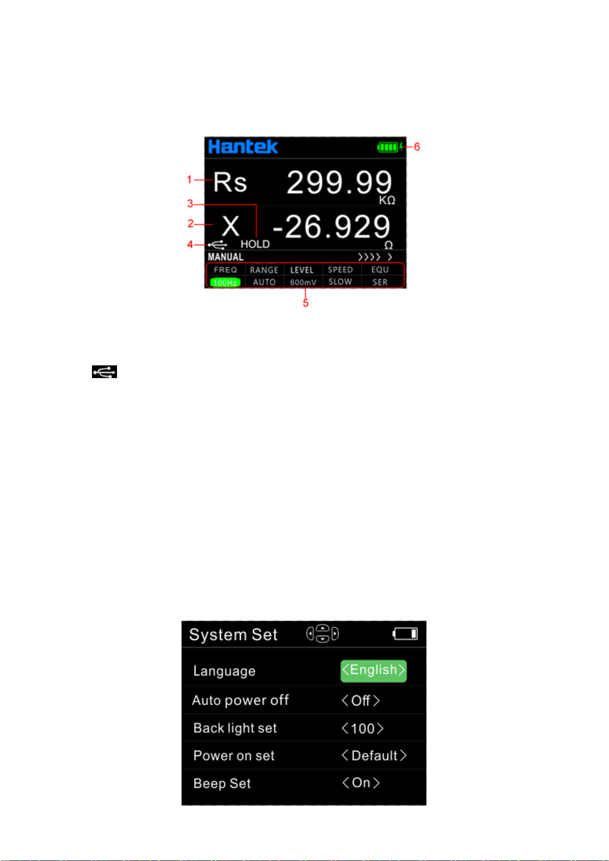
On the system settings interface users can set the language, auto power off, brightness, power
setting and buzzer. And view the model and version of the instrument.
Press [SET] key to enter the system setting interface, press the arrow key to select the setting
option and highlight, and press the arrow key for specific setting. Then press the [SET] button
again to view the model and version of the instrument. Press [SET] key again to exit the system
setting interface.
Power on setting:
Default: If the power on setting is <default>, all setting will be system default for next start.
Last: If the boot setting is <Last>, the test parameters, system language, automatic shutdown,
back light setting and beep setting will be saved for the next start.
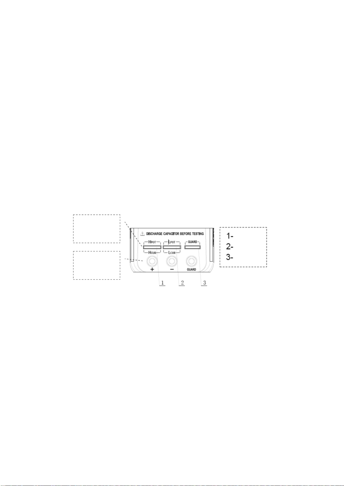
1.3 Test port
The serial LCR uses the 3-terminal and 5-terminal test ports at the same time, which is to
combine convenience and high accuracy for the test. See the figure for the test terminal.
Complete
five terminal
test hole
Access three
terminal test
hole
HI
LO
GUARD
The three-terminal test port of the instrument uses the standard rubber jack, therefore the
inexpensive rubber plug- alligator clip can be used as the test line. It is very convenient to apply
the extended test, but the drawback is low testing accuracy.
To improve the accuracy of the test line when using the extension line, the LCR is also equipped
with the five-terminal test notch for dedicated test fixture. It renders possible the complete
four-terminal measurement of the extension line to ensure the high testing accuracy.
8
Chapter 2 Operation instruction
2.1 Startup and shutdown
Press the power key to start the instrument and the measurement interface is shown (default).
Press the power key again to shutdown it.
2.2 Test parameter
2.2.1 Test frequency
Handheld LCR applies AC test signal to the DUT for measurement. Frequency is one of the main
parameters of the AC source. Due to the presence of the non-ideal and distributed parameters of
component, and the impact of the distributed parameters between the test terminals, the same
component may have different results with different test frequencies. So, please select
appropriate frequency to test.
There are two ways to change the test frequency:
Method 1: Press [FREQ] key to switch different frequencies.
Method 2: Press the right and left arrow keys to move the cursor to the FREQ zone as shown in
below figure, and press the up and down arrow keys to switch frequencies.
2.2.2 Test level
Handheld LCR applies AC test signal to the DUT for measurement. Both the frequency and signal
level can be changed.
There are two ways to change the test level:
Method 1: Press [LEVEL] key to switch between different test signals level.
Method 2: Press the right and left arrow keys to move the cursor to the LEVEL zone, and press
the up and down arrow keys to switch levels.

9
2.2.3 Test range
There are two ways to change the test range:
Method 1: Press [RANGE] key to switch between different test ranges.
Method 2: Turn on the instrument and the measurement display is shown, press the left and right
arrow keys to move the cursor to the RANGE zone, and the up and down arrow keys to switch the
range (AUTO, 100Ω, 1kΩ, 10kΩ, 100kΩ).
2.2.4 Test speed
There are two ways to change the test speed:
Method 1: Turn on the instrument and the measurement display is shown, press [SPEED] to
switch to the next measurement speed (fast, medium, slow). Above the status bar the
corresponding measurement speed is displayed. Fast (4 times /s), Medium (2 times /s), Slow (1
time /s).
Method 2: Turn on the instrument and the measurement display is shown, press the left and right
arrow keys to move the cursor to the SPEED zone, and the up and down arrow keys to switch the
test speed.
2.2.5 Main parameters
Parameter and symbol
R: resistance C: capacitance L: inductance Z: impedance
Select the type of measurement parameter, then select the main parameter.
Press [AUTO/R/L/C/Z] key to switch the main parameters(R, L, C, Z and AUTO) in sequence.
When AUTO is selected for the main parameter, the main parameter font is shown in red.
2.2.6 Secondary parameters
Parameter and symbol
X: reactance D: dissipation factor Q: quality factor θ: phase angle
ESR: equivalent series resistance
If necessary, press [X/D/Q/θ/ESR] key to select the secondary parameter.
If the main parameter select as Auto, this key will not work.
2.2.7 Set nominal value of tolerance mode
The method of setting the nominal value is as follows:
1. Turn on the instrument and the measurement display is shown, the component with required
nominal should be placed on the test clip of the instrument.
2. Long press [COMPARE] to turn on the comparator, and the nominal value is the value of the
measured element.
The nominal value and tolerance will be displayed in the status bar as shown in the below figure.
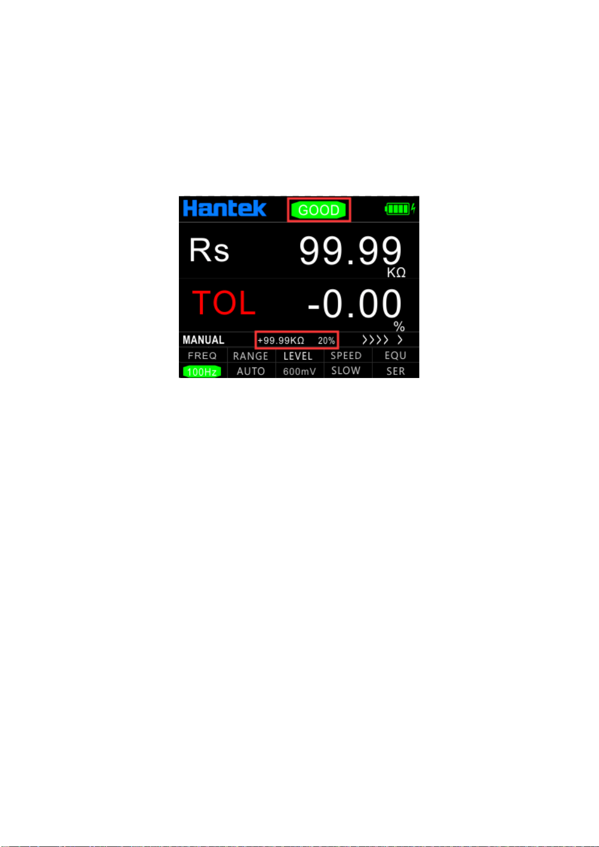
10
The deviation value between current test value and standard value will display on the secondary
parameter position.
Short press this key to select the required tolerance value successively (1%, 5%, 10% and 20%
optional). The color bar at the top of the screen will be used to judge GOOD/NG. Green GOOD
means within tolerance, red NG means beyond tolerance, the indicator light of this key lights up at
the same time.
Long press this button or change the primary and secondary parameters to exit this function.
Note: This function cannot work if the main parameter select as Auto.
2.2.8 Equivalent mode
Due to the non-ideal and distributed parameters of component, the actual components tend to be
equivalent with the combination of ideal elements. Generally LCR tester uses two simple
equivalent models--series and parallel. Selecting the proper equivalent model will lead to better
measurement results. In general, low-impedance elements (such as that below 100Ω) should use
the series equivalent model; a high impedance element (such as that above 10kΩ) should use the
parallel equivalent model; the equivalent model affects less the measurement result of the one in
between the two above models.
Press [SER/PAL] key to switch equivalent mode (SER, PAL).
2.3 Relative mode
Press [REL] to turn on the relative function and the current value is used as reference. The
reference value and relative value will be shown respectively on the secondary and main display.
Press the key again to exit the function.
2.4 Reading hold mode (HOLD)
The data hold function is used to freeze the displayed data. The measurement is still in progress,
but the data on the LCD is not updated as the measurements proceed.
Turn on reading hold:

11
Press the [HOLD] key, and "LOLD" will be shown on the LCD to indicate that the data hold
function is activated. And measurement results for the main and secondary parameters are those
displayed before pressing the HOLD key.
Turn off reading hold:
In hold mode, press again the [HOLD] key, and "HOLD" disappears from the LCD, the instrument
returns to normal measurement mode.
2.5 Data recording function
If the measurement data of the DUT see poor stability and fluctuate within a certain range, use the
data recording mode to acquire the readings. In the data recording mode, the maximum, minimum
and average can be dynamically obtained within a certain range.
Turn on the recording function:
Press [RECORD] key to turn on the data recording function, and the recorded value is shown on
the secondary display, then press the key to select the display of the maximum, minimum, or
average in successively.
This function records the maximum value, minimum value of the main parameter and the average
value of the last ten tests.
Note: After changing the type of the measurement parameter, it will
automatically exit from the data recording function. This function cannot work
if the main parameter select as Auto.
2.6 Correction function
The correction function includes the open and short circuit. By correcting it can effectively reduce
the error of distributed parameters caused by the test line. The short circuit correction can reduce
the impact of the contact resistance and lead resistance on the measurement of low impedance
element. The open circuit correction can reduce the impact of the distributed capacitance and
resistance between the two ends of the test line on the measurement of high impedance element.
The method of correction is shown as follows:
1. Before entering the correction function, please ensure that the test terminals are open- or
short-circuited. Long press [REL] key to enter the correction interface.
12
2. Short press [REL] key for open (OPEN) or short (SHORT) circuit correction, then the
instrument detects automatically whether it is open or short circuit. If the correction is
successful, the secondary display shows "SUCCESS"; or it shows "FAILED".
Note: Do not change the state of the test terminals during the correction.
3. Once finished the correction ends, press [REL] key to return to the measurement display.
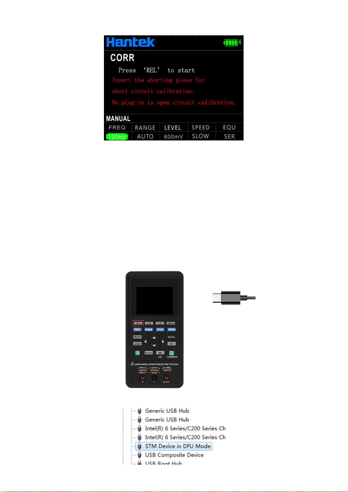
2.7 Firmware Update
1. Download the tool "DfuSe Demo v3.0.5" and install it. Download upgrade firmware (***. Dfu).
2. In the shutdown state, keep pressing R-X key and insert the USB cable into the Type C port of
the device to connect the device to the computer.
You can see the device is identified in device manager of the PC:
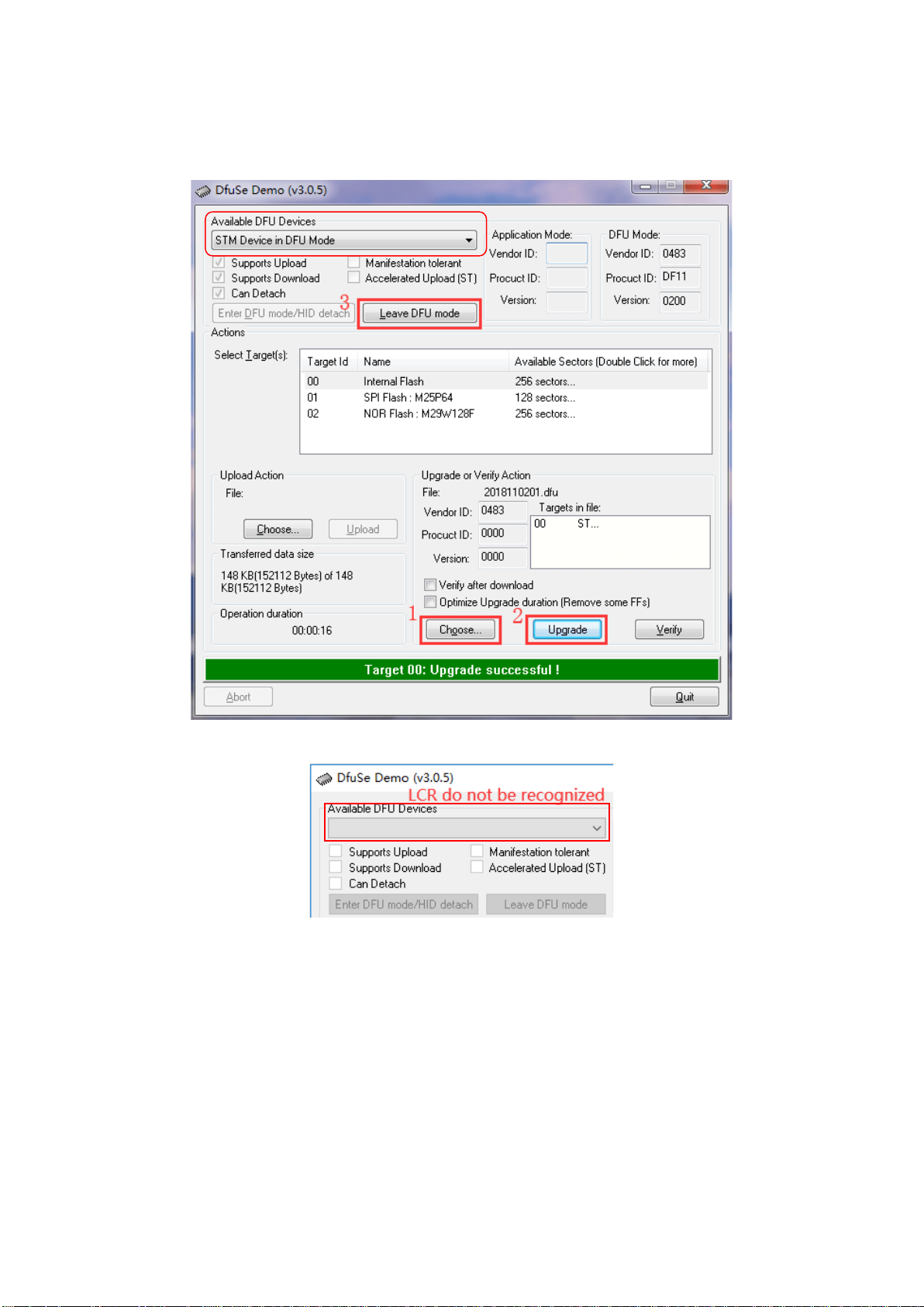
13
3. Open DfuSe Demo software, click "Choose" button to select the Upgrade firmware (***. Dfu),
and click "Upgrade" to Upgrade it. After finished it, click "Leave DFU mode" to exit the
programming mode.
If the device is not identified, please repeat step 2.
4. Close the “DfuSe Demo” software.

14
Chapter 3 Quick application guide
Warning:
⚫ Do not measure the charged capacitor, or it may cause damage to the
instrument.
⚫ In case of measurement of on-board devices, make sure the power is turned
off. The active circuit cannot be measured directly.
⚫ When used in the dusty environment, the instrument is easy to gather dirt,
so it should be cleaned periodically to protect the test port to prevent the
dust from entering the instrument. The accumulation of dust will be
conductive and affect the use of the instrument.
⚫ Do not place the instrument directly in the environments with explosives,
direct sunlight and excessive heat.
Reminder: To achieve the proper measurement accuracy, refer to the
"correction function" section for open and short circuit correction before the
measurement. The test fixture can be rubber plug - alligator clip (see figure), or
the component can be directly inserted into the test notch. The rubber plug -
alligator clips are mainly used in the following examples.
15
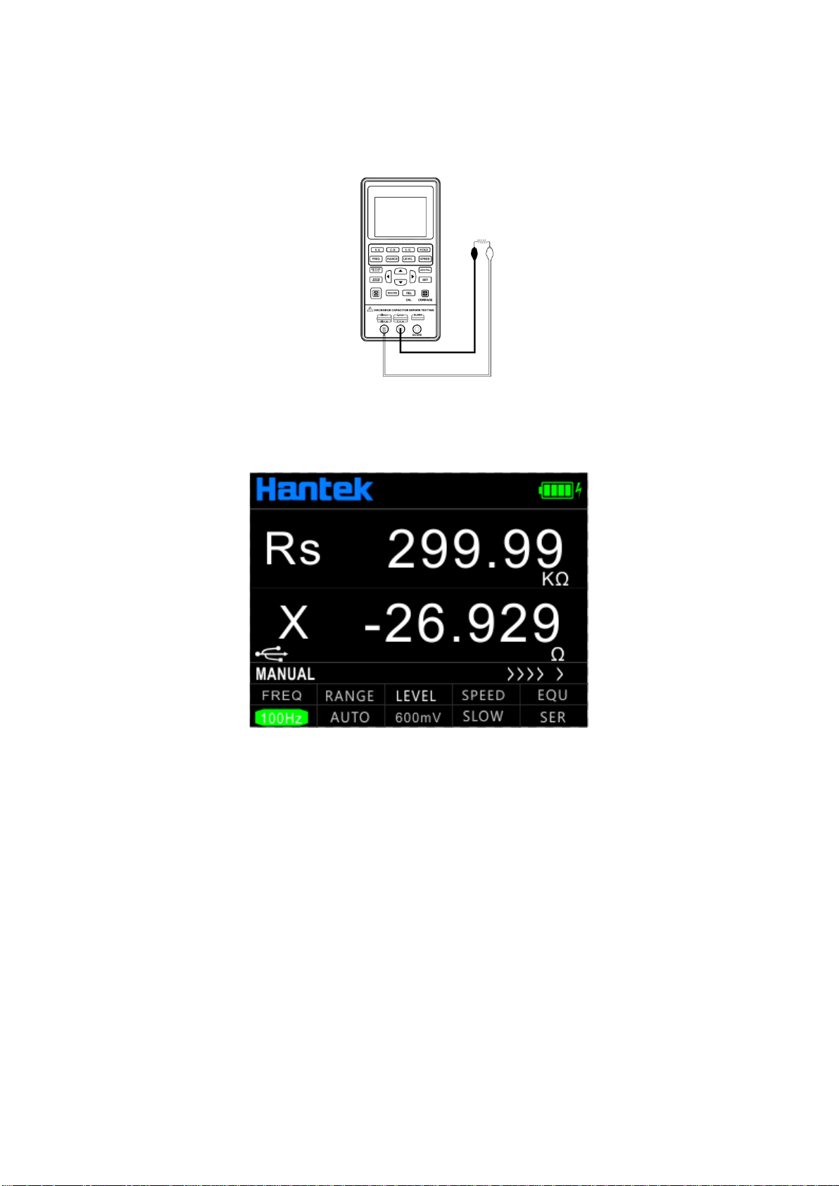
3.1 Resistance measurement
See the below figure for the connection test.
1. Press the power key to start the instrument.
2. Press the [AUTO/R/C/L/Z] key until Rs/Rp is displayed on the interface which means to select
resistance measurement.
3. Insert the resistor into the test notch, or choose the appropriate test accessories (rubber plug -
alligator clip) and connect it with the measured resistance.
4. Press the [FREQ] key to select the desired test frequency, press [LEVEL] to select the desired
level.
5. Read the measurement results from the screen.
Note: the AC signal is used by the instrument to measure the resistance, so the test result
reflects the AC resistance characteristics of the instrument instead of its DC resistance.
16
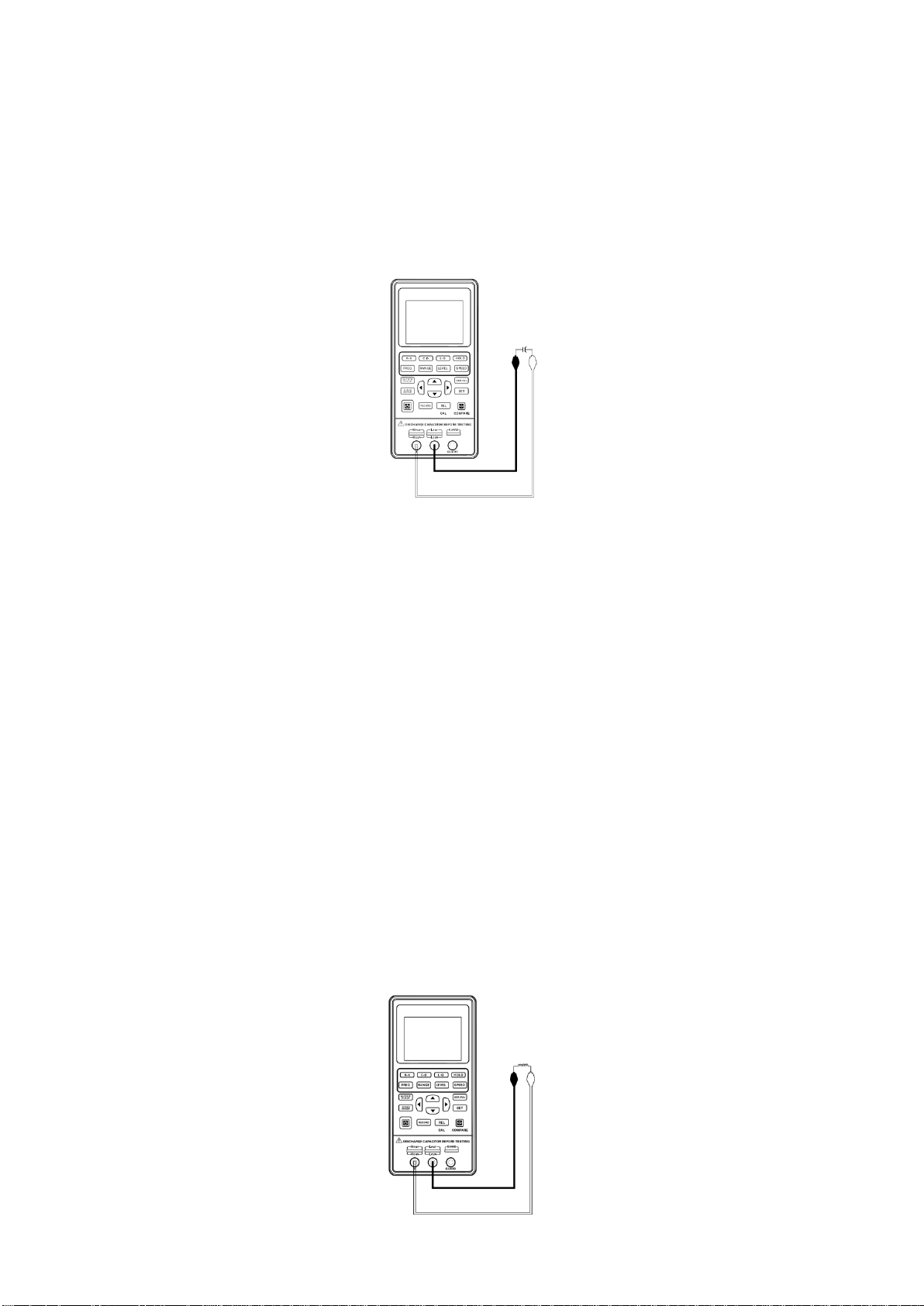
3.2 Capacitance measurement
Warning: Make sure that the capacitor has been fully discharged before
measuring.
See the below figure for the connection test.
1. Press the power key to start the instrument.
2. Press the [AUTO/R/C/L/Z] key until Cs/Cp is displayed on the interface which means to select
capacitance measurement.
3. Insert the capacitor into the test notch, or choose the appropriate test accessories (rubber plug
- alligator clip) and connect it with the measured capacitor.
4. Press the [FREQ] key to select the desired test frequency, press [LEVEL] key to select the
desired level.
5. Read the measurement results from the screen.
Note: The capacitor or capacitive device must be fully discharged before
the test; the capacitor with large capacity may need longer time to discharge. If
the capacitive device not fully discharged is connected, it can damage the
components inside the instrument.
3.3 Inductance measurement
See below figure for the connection test.

17
1. Press the power key to start the instrument.
2. Press the [AUTO/R/C/L/Z] key until Ls/Lp is displayed on the interface which means to select
inductance measurement.
3. Insert the inductor into the test notch, or choose the appropriate test accessories (rubber plug -
alligator clip, Kelvin test fixture, etc.) and connect it with the measured inductor.
4. Press the [FREQ] key to select the desired test frequency, press [LEVEL] to select the desired
level.
5. Read the measurement results from the screen.
3.4 Impedance measurement
1. Press the power key to start the instrument.
2. Press the [AUTO/R/C/L/Z] key until Z is displayed on the interface which means to select
impedance measurement.
3. Insert the impeder into the test notch, or choose the appropriate test accessories (rubber plug -
alligator clip, Kelvin test fixture, etc.) and connect it with the measured impeder.
4. Press the [FREQ] key to select the desired test frequency, press [LEVEL] to select the desired
level.
5. Read the measurement results from the screen.
18
Chapter 4 Telecommunication
The instrument can be connected to PC through the Type C-USB interface. After installing the
driver on the PC, handheld LCR can be controlled from or the test results acquired by the PC
through the virtual serial port.
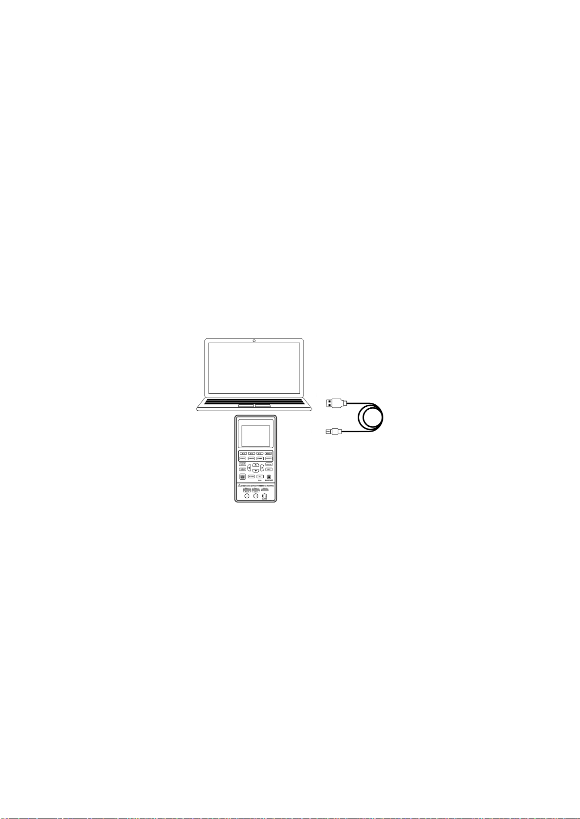
4.1 Connect the instrument to PC
Please refer to following steps to connect to PC:
1. Locate the USB driver software in the CD.
2. Use the Type C-USB cable to connect the instrument to the USB port of the PC, shown in
below Figure, press the power key to start the instrument.
3. After the installation is completed, check the serial number in Windows’ Device Manager.
Remote Control State:
When the LCR receives the remote operation state instruction from the host, the instrument
automatically enters into the remote control state. USB icon is displayed in green to show the
entry into the remote control state. To exit the remote control state, please send the “*GTL”
command.
Command Protocol:
Handheld LCR uses SCPI command set to transfer control command and return query
information and data with string. The terminator specified by the protocal shows the end of a
command line or information enquiry line.
Using SCPI command set enables the interaction control of PC over the instrument by
programming. The command format meets the standard which is easy to understand and use.
19
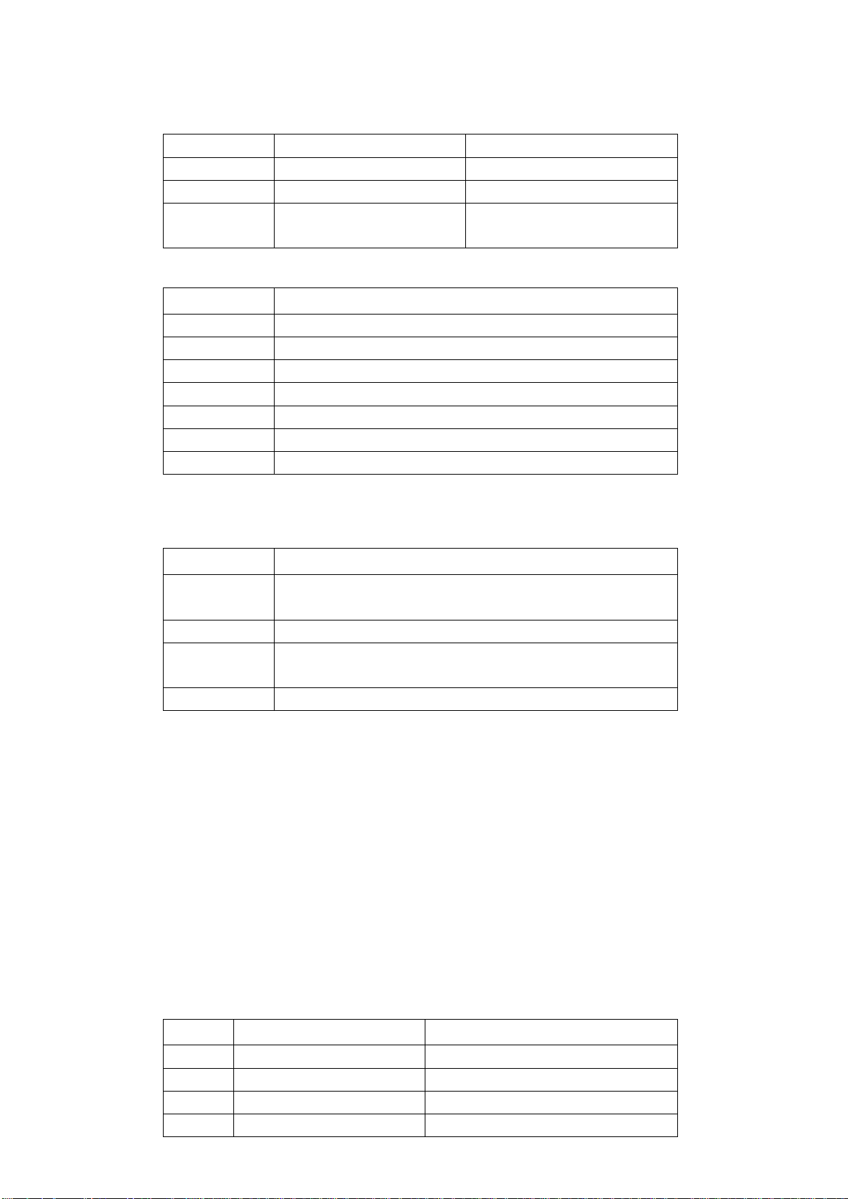
Data type
The data in the form of ASCII characters transmitted on the bus may have the following types:
Type
Meaning
Example
<NR1>
Integer
+800,-200,100
<NR2>
Decimal
+1.56,-0.001
<NR3>
Exponential floating
number
+2.345678E+04
-1.345678E-02
Rules of grammar
Notation
Definition
:
Colon, enter the next level of the command
;
Semicolon, the same level of command
*
Asterisk, public command
,
Comma, multi-parameter separator
?
Question mark indicates the query
Spacing, separating commands and parameters
“ ”
Quotes for quoted part
Symbol used in instruction
These marks are added in order to specify the command format, but are not part of the command.
Marks
Definition
[ ]
The optional command parameters are given in the square
brackets
|
Division mark—to select one from many
< >
The definition of the variable parameter is given or the
variable parameters listed in the angle brackets
( )
Interpretation which is not seen in the actual command
Abbreviations and capitalization:
1) The command has full format and abbreviated format, in the following descriptions of the
command, capitalization represents abbreviation, and the abbreviated command has the
same effect with the complete command;
2) Abbreviations are generally expressed by four letters of the complete command, the
random abbreviation which does not appear in the command table will be considered as
the wrong command;
3) There is no difference regarding capitalization for ASCII command actually transmitted
on the bus and the letters of parameter.
Error code
Code
Content
Definition
E10
Unknown Command!
Unknown Command!
E11
Parameter Error!
Parameter Error!
E12
Syntax Error!
Syntax Error!
E13
Data Not Ready!
Data Not Ready!

20
Terminator
You can choose anyone of the following characters to end.
<CR> (Enter 0x0D)
<LF> (Line break 0x0A)
<CR> <LF>
4.2 Command Reference
4.2.1 Public command
Public command applied universally to various kinds of instrument defined by the public
command IEEE488, the public command starts with *. For example, *IDN?,*GTL,*LLO. This
machine supports only a few Public commands.
(1) *IDN?
Description: inquiry instrument information and version information
Return: < instrument hardware name >, < software version >, < serial number >,
< hardware version >
(2) *GTL
Description: used to unlock keyboard and resume keyboard operation
Return: None
4.2.2 Subsystem commands
FREQuency Subsystem
(1) FREQuency <value>
Description: set the measurement frequency
Parameter: 100, 120, 400, 1000, 4000, 10000, 40000, 50000, 75000, 100000 or
100Hz,120Hz, 400Hz, 1kHz, 4kHz, 10kHz ,40kHz, 50kHz, 75kHz, 100kHz (Please refer to the
model of LCR.)
Return: None
(2) FREQuency ?
Description: query current test frequency
Parameter: None
Return: <100|120|400|1000|4000|10000|40000|50000|75000|100000>(Please refer to the
FUNCtion Subsystem
(1) FUNCtion:impa <R|L|C|Z|Auto>
Description: Select the main parameter type
Parameter: <R|L|C|Z|Auto>
Return: None
(2) FUNCtion:impa ?

21
Description: Query the main parameter type
Parameter: None
Return: <l-auto|c-auto|z-auto|r|l|c>
(3) FUNCtion:impb <X|Q|D|THETA|ESR>
Description: Select a secondary parameter type
Parameter: <X|Q|D|THETA|ESR>
Return: None
(4) FUNCtion:impb ?
Description: Query a secondary parameter type
Parameter: None
Return: <rec|q-auto|d-auto|theta-auto|x|q|d|theta|esr>
(5) FUNCtion:RANGe <AUTO|10|100|1000|10000|100000>
Or FUNCtion:RANGe <AUTO|10ohm|100ohm|1kohm|10kohm|100kohm>
Description: Select the range
Parameter: <AUTO|10|100|1000|10000|100000>
Or <AUTO|10ohm|100ohm|1kohm|10kohm|100kohm>
Return: None
(6) FUNCtion: RANGe ?
Description: Query the range
Parameter: None
Return: <auto|10|100|1000|10000|100000>
(7) FUNCtion:LEVel <300|600>
Or FUNCtion: LEVel <300mv|600mv>
Description: Select the level
Parameter: <300|600> or <300mv|600mv>
Return: None
(8) FUNCtion: LEVel ?
Description: Query the level
Parameter: None
Return: <300|600>
(9) FUNCtion:EQUivalent <SER|PAL>
Or FUNCtion:EQUivalent <SERIES| PARALLEL>
Description: Select the equivalent mode
Parameter: <SER|PAL> or <SERIES| PARALLEL>
Return: None
(10) FUNCtion: EQUivalent ?
Description: Query the equivalent mode
Parameter: None
Return: <ser|pal>
FETCh Subsystem

22
FETCh ?
Description: Query data
Parameter: None
Return: <NR3,NR3,NR1> Main parameters, secondary parameters, gear number
23
Chapter 5 Specification
The general and measurement precision specification of LCR are described below.
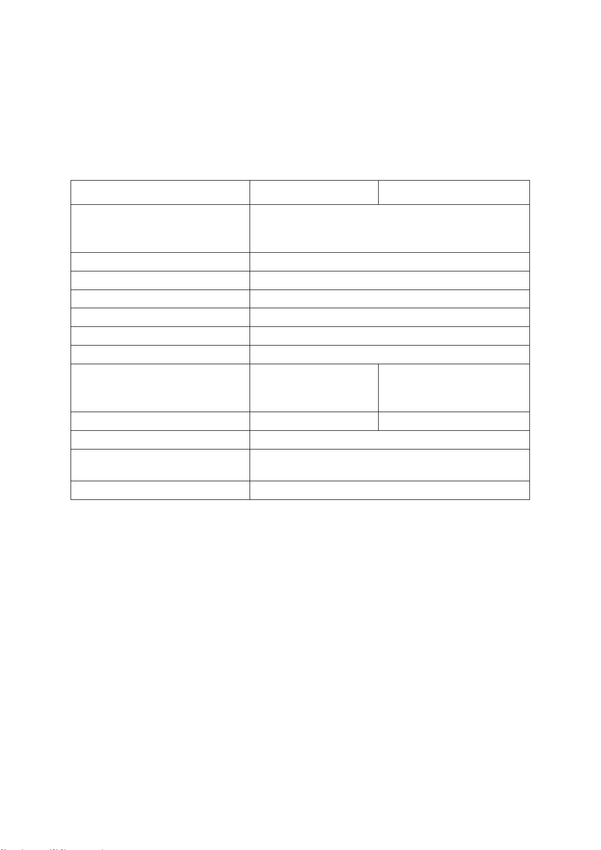
5.1 General Specification
Model
Hantek1832C
Hantek1833C
Measurement parameters
Main parameter: L/C/R/Z Secondary parameter:
X/D/Q/θ/ESR
Equivalent mode
Series, parallel
Mode of range
Manual, automatic
Measurement speed
Fast(4 times/s), medium(2 times/s), slow(1 times/s)
Configuration of the test terminal
3-terminal, 5-terminal
Correction function
Short circuit, Open circuit
Communication interface
Type C(virtual serial port)
Test signal frequency
100Hz, 120Hz, 400Hz,
1kHz, 4KHz, 10kHz,
40kHz
100Hz, 120Hz, 400Hz, 1kHz,
4KHz, 10kHz, 40kHz, 50KHz,
75KHz, 100kHz
Test signal level
0.6Vrms
0.3Vrms, 0.6Vrms
Output impedance
100Ω
Highest accuracy (see accuracy
index for details)
Resistance: 0.25%
Capacitance: 0.4%
Measurement range
L: 0-2000H C: 0-20mF R: 0-20MΩ
5.2 Accuracy
Notes:
➢ Environment temperature: 20
℃
± 2
℃
, humidity: ≤75% R.H;
➢ Preheat the instrument for at least 30 minutes before the test;
➢ Test at the test notch on the end face of the instrument;
➢ It is better to conduct open and short circuit correction before the test;
➢ Measure with the recommended equivalent mode;
➢ The percentage in terms of error indicates:
➢ ± (% of the reading + last digit)
➢ If the actual measurement of the instrument and the display exceeds the
scope specified in the table, the accuracy of the excessive part will not be
given;
➢ The meaning of the subscript
➢ S- series equivalent; p- parallel equivalent; e- accuracy
➢ Some parameters cannot be given in the data table, and it can only be
calculated based on the measurement results;
24
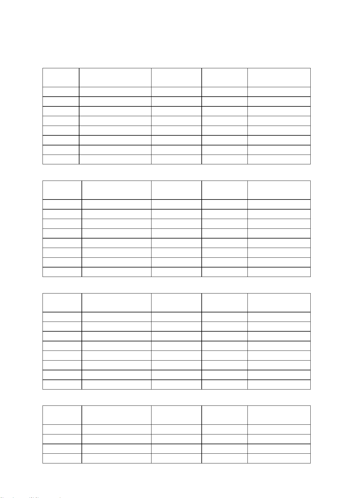
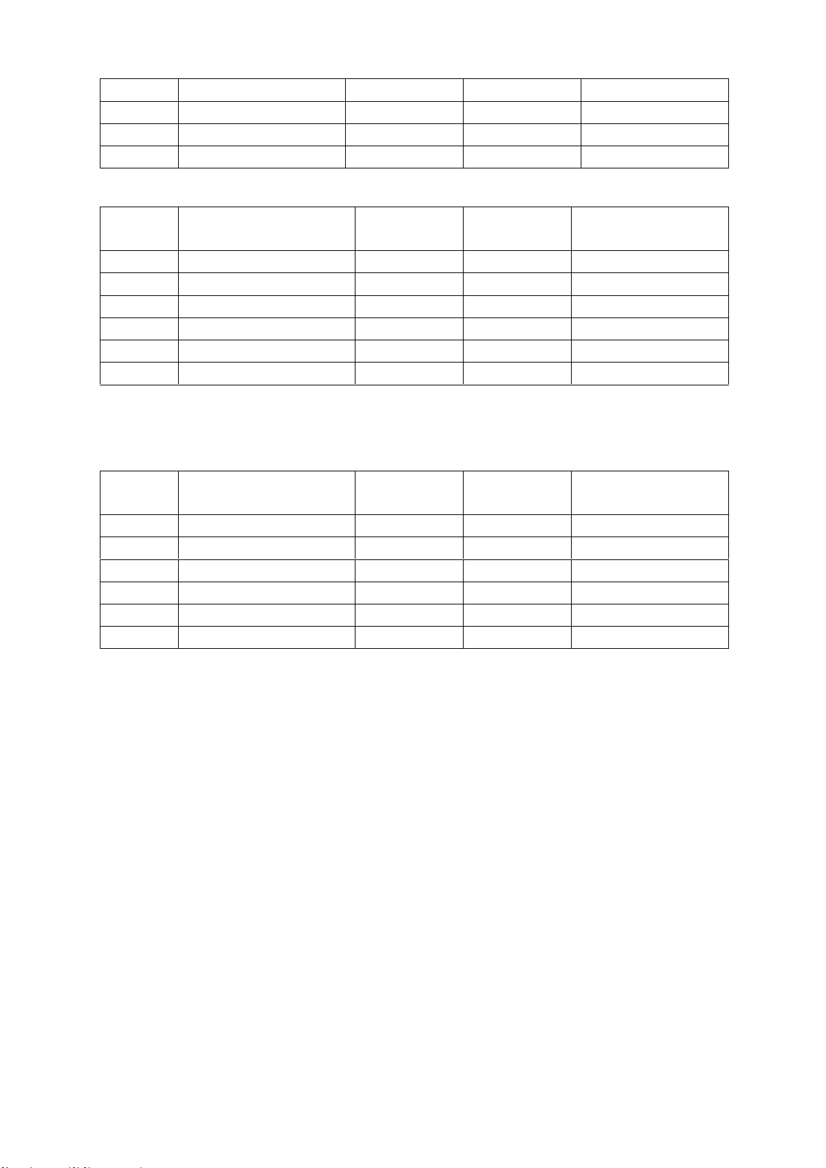
Capacitance C and dissipation D
◼ 100Hz/120Hz/400Hz
Range
Range of display
Accuracy Ce
Accuracy De
Equivalent mode
recommended
20mF
4.000mF∼20.000mF
8.00%+5 digits
0.0800
Series
4mF
400.0μF∼3.9999mF
2.00%+3 digits
0.0200
Series
400μF
40.00μF∼399.99μF
0.60%+2 digits
0.0060
Series
40μF
4.000μF∼39.999μF
0.40%+2 digits
0.0040
Series
4μF
400.0nF∼3.9999μF
0.40%+2 digits
0.0040
----
400nF
40.00nF∼399.99nF
0.4%+2 digits
0.0040
Parallel
40nF
4.000nF∼39.999nF
0.5%+3 digits
0.0050
Parallel
4nF
0pF∼3.999nF
1.5%+5 digits
------
Parallel
◼ 1kHz/4KHz
Range
Range of display
Accuracy Ce
Accuracy De
Equivalent mode
recommended
1000uF
400.0uF∼999.9uF
3.00%+5 digits
0.0300
Series
400μF
40.00μF∼399.99μF
1.50%+3 digits
0.0150
Series
40μF
4.000μF∼39.999μF
0.60%+2 digits
0.0060
Series
4μF
400.0nF∼3.9999μF
0.40%+2 digits
0.0040
----
400nF
40.00nF∼399.99nF
0.4%+2 digits
0.0040
Parallel
40nF
4.000nF∼39.999nF
0.6%+3 digits
0.0060
Parallel
4nF
400.0pF∼3.9999nF
0.6%+3 digits
0.0060
Parallel
400pF
0.0pF~399.9pF
3%+5 digits
------
Parallel
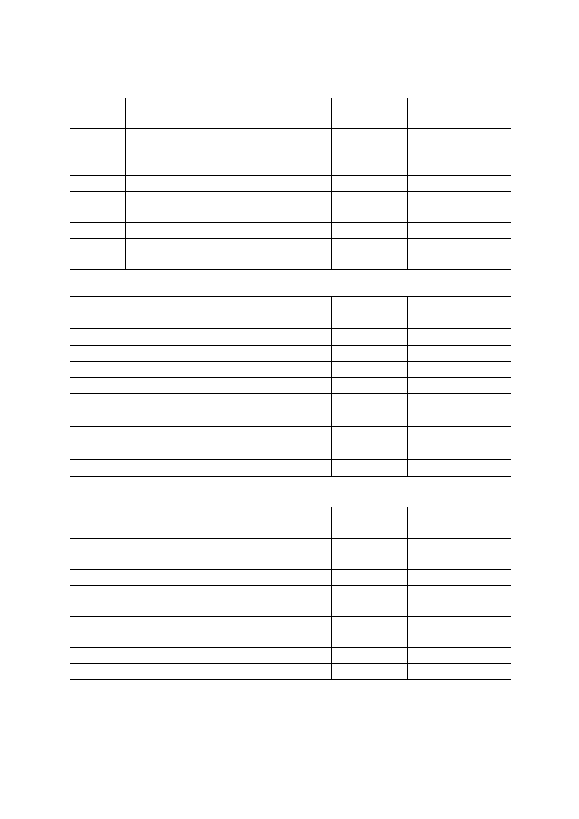
◼ 10kHz
Range
Range of display
Accuracy Ce
Accuracy De
Equivalent mode
recommended
100μF
40.00μF∼100.00μF
4.00%+5 digits
0.0400
Series
40μF
4.000μF∼39.999μF
2.0%+3 digits
0.0200
Series
4μF
400.0nF∼3.9999μF
0.60%+2 digits
0.0060
Series
400nF
40.00nF∼399.99nF
0.4%+2 digits
0.0040
Series
40nF
4.000nF∼39.999nF
0.4%+2 digits
0.0040
------
4nF
400.0pF∼3.9999nF
0.4%+2 digits
0.0040
Parallel
400pF
40.00pF~399.99pF
0.6%+3 digits
0.0060
Parallel
40pF
0.00pF~39.99pF
2.5%+5 digits
------
Parallel
◼ 40kHz/50KHz
Range
Range of display
Accuracy Ce
Accuracy De
Equivalent mode
recommended
100μF
40.00μF∼100.00μF
6.00%+5 digits
0.0600
Series
40μF
4.000μF∼39.999μF
4.0%+3 digits
0.0400
Series
4μF
400.0nF∼3.9999μF
1.0%+2 digits
0.0100
Series
400nF
40.00nF∼399.99nF
0.6%+2 digits
0.0060
Series
25
40nF
4.000nF∼39.999nF
0.6%+2 digits
0.0060
------
4nF
400.0pF∼3.9999nF
0.6%+2 digits
0.0060
Parallel
400pF
40.00pF~399.99pF
1%+3 digits
0.0100
Parallel
40pF
0.000pF~39.999pF
3%+5 digits
------
Parallel
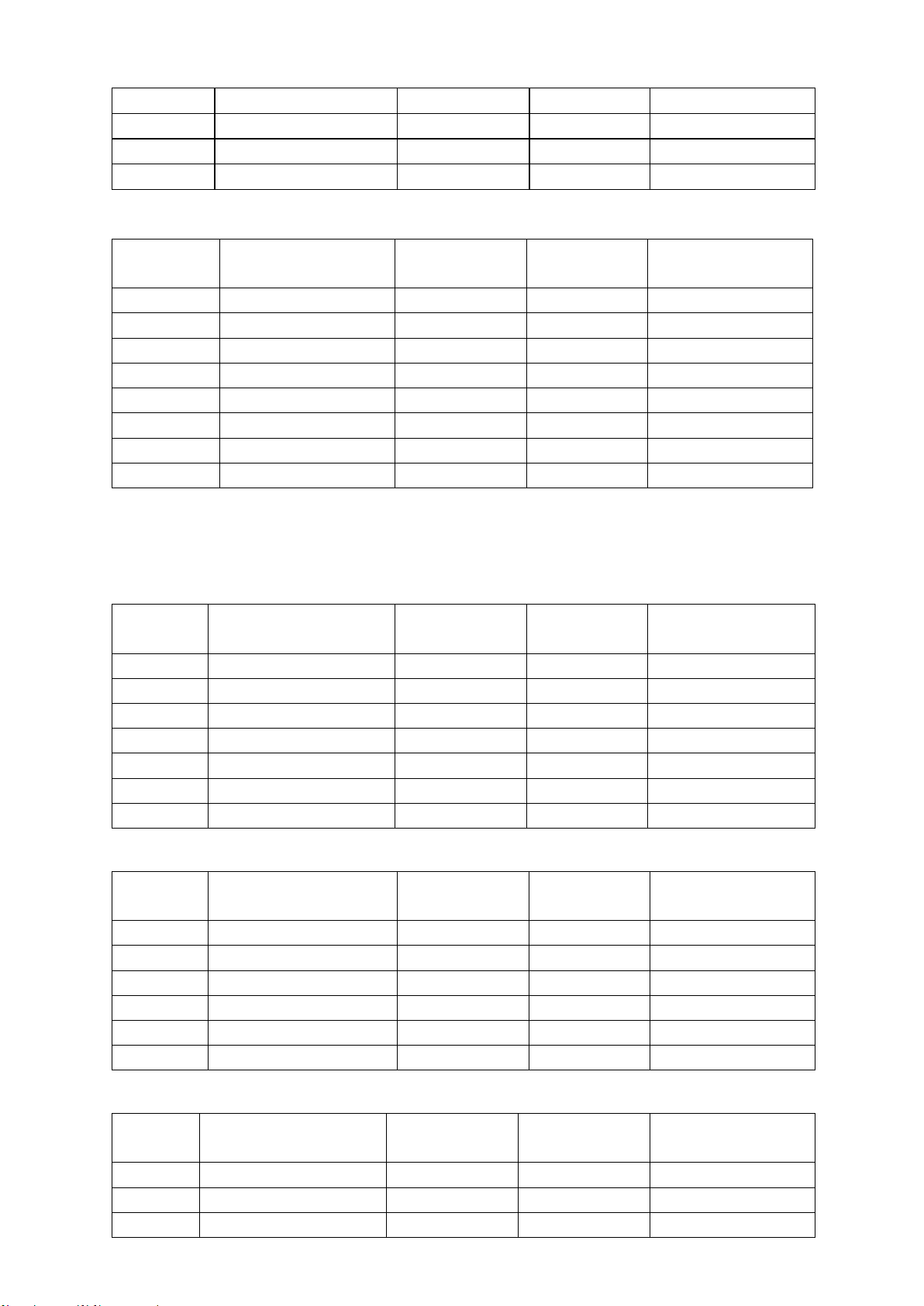
◼ 75KHz/100kHz
Inductance L and quality factor
◼ 100Hz/120Hz/400Hz
◼ 1kHz/4KHz
Range
Range of display
Accuracy Le
Accuracy
De*
Equivalent mode
recommended
1H
400.0mH∼999.9mH
1.50%+3 digits
0.0150
Parallel
400mH
40.00mH∼399.99mH
0.4%+2 digits
0.0040
Parallel
40mH
4.000mH∼39.999mH
0.4%+2 digits
0.0040
------
4mH
400.0uH∼3.9999mH
0.4%+2 digits
0.0040
Series
400uH
40.00uH~399.99uH
0.8%+3 digits
0.0080
Series
40uH
0.0uH~39.9uH
3.0%+5 digits
------
Series
◼ 10kHz/40KHz
Range
Range of display
Accuracy Le
Accuracy De*
Equivalent mode
recommended
100H
40.00H∼100.00H
2.0%+3 digits
0.0200
Parallel
40H
4.000H∼39.999H
0.60%+2 digits
0.0060
Parallel
4H
400.0mH∼3.9999H
0.40%+2 digits
0.0040
Parallel
Range
Range of display
Accuracy Ce
Accuracy De
Equivalent mode
recommended
10μF
4.000μF∼10.000μF
8.0%+20 digits
0.0800
Series
4μF
400.0nF∼3.9999μF
5.0%+10 digits
0.050
Series
400nF
40.00nF∼399.99nF
1.5%+5 digits
0.0150
Series
40nF
4.000nF∼39.999nF
1%+2 digits
0.0100
Series
4nF
400.0pF∼3.999nF
1%+2 digits
0.0100
------
400pF
40.00pF~399.99pF
1.5%+2 digits
0.0150
Parallel
40pF
4.000pF~39.999pF
2%+5 digits
0.0200
Parallel
4pF
0.000pF~3.999pF
5%+10 digits
------
Parallel
Range
Range of display
Accuracy Le
Accuracy
De*
Equivalent mode
recommended
1000H
400.0H∼999.9H
2.00%+3 digits
0.0200
Parallel
400H
40.00H∼399.99H
0.60%+2 digits
0.0060
Parallel
40H
4.000H∼39.999H
0.40%+2 digits
0.0040
Parallel
4H
400.0mH∼3.9999H
0.40%+2 digits
0.0040
----
400mH
40.00mH∼399.99mH
0.4%+2 digits
0.0040
Series
40mH
4.000mH∼39.999mH
0.6%+3 digits
0.0060
Series
4mH
0uH∼3.999mH
3.0%+5 digits
------
Series
26
400mH
40.00mH∼399.99mH
0.4%+2 digits
0.0040
------
40mH
4.000mH∼39.999mH
0.4%+2 digits
0.0040
Series
4mH
400.0uH∼3.9999mH
1%+3 digits
0.0100
Series
400uH
0.00uH~399.99uH
3.0%+5 digits
------
Series
◼ 40kHz/50KHz
Range
Range of display
Accuracy Le
Accuracy
De*
Equivalent mode
recommended
1H
400.0mH∼999.9mH
2.0%+4 digits
0.0200
Parallel
400mH
40.00mH∼399.99mH
0.8%+2 digits
0.0080
Parallel
40mH
4.000mH∼39.999mH
0.8%+2 digits
0.0080
------
4mH
400.0uH∼3.9999mH
0.8%+2 digits
0.0080
Series
400uH
40.00uH~399.99uH
1.5%+3 digits
0.0150
Series
40uH
0.000uH~39.999uH
4.0%+5 digits
------
Series
Note*: please calculate the quality factor according to the formula to calculate the
accuracy of Q.
◼ 75KHz/100kHz
Range
Range of display
Accuracy Le
Accuracy
De*
Equivalent mode
recommended
400mH
40.00mH∼399.99mH
2.5%+2 digits
0.0250
Parallel
40mH
4.000mH∼39.999mH
1.5%+2 digits
0.0150
Parallel
4mH
400.0μH∼3.9999mH
1.0%+2 digits
0.0100
------
400μH
40.00μH~399.99μH
1.0%+2 digits
0.0100
Series
40μH
4.000μH~39.999μH
1.5%+5 digits
0.0150
Series
4μH
0.000μH~3.999μH
4%+10 digits
------
Series
27
Impedance Z and phase angle
◼ 100Hz/120Hz/400Hz/1kHz/4KHz/10kHz
Range
Range of display
Accuracy Ze
Accuracy
e
Equivalent mode
recommended
20MΩ
4.000MΩ~20.000MΩ
3.0%+10 digits
3.4°
Parallel
4MΩ
400.0kΩ~3.9999MΩ
1.2%+3 digits
0.7°
Parallel
400kΩ
40.00kΩ~399.99kΩ
0.3%+3 digits
0.2°
Parallel
40kΩ
4.000kΩ~39.999kΩ
0.25%+2 digits
0.1°
------
4kΩ
400.0Ω~3.9999kΩ
0.25%+2 digits
0.1°
Series
400Ω
40.00Ω~399.99Ω
0.25%+2 digits
0.1°
Series
40Ω
4.000Ω~39.999Ω
0.5%+3 digits
0.3°
Series
4Ω
0.4000Ω~3.9999Ω
2.0%+3 digits
1.1°
Series
0.4Ω
0.0000Ω~0.3999Ω
4.0%+3 digits
------
Series
◼ 40kHz/50KHz
Range
Range of display
Accuracy Ze
Accuracy
e
Equivalent mode
recommended
20MΩ
4.000MΩ~20.000MΩ
7.0%+41 digits
4.0°
Parallel
4MΩ
400.0kΩ~3.9999MΩ
2.5%+3 digits
1.4°
Parallel
400kΩ
40.00kΩ~399.99kΩ
1.0%+4 digits
0.6°
Parallel
40kΩ
4.000kΩ~39.999kΩ
1.0%+4 digits
0.6°
------
4kΩ
400.0Ω~3.9999kΩ
0.5%+3 digits
0.3°
Series
400Ω
40.00Ω~399.99Ω
0.5%+3 digits
0.3°
Series
40Ω
4.000Ω~39.999Ω
0.7%+4 digits
0.4°
Series
4Ω
0.4000Ω~3.9999Ω
2.0%+6 digits
1.1°
Series
0.4Ω
0.0000Ω~0.3999Ω
5.0%+10 digits
------
Series
◼ 75KHz/100kHz
Range
Range of display
Accuracy Ze
Accuracy
e
Equivalent mode
recommended
20MΩ
4.000MΩ~20.000MΩ
9.0%+20 digits
5.2°
Parallel
4MΩ
400.0kΩ~3.9999MΩ
4.0%+10 digits
2.3°
Parallel
400kΩ
40.00kΩ~399.99kΩ
1.5%+4 digits
0.9°
Parallel
40kΩ
4.000kΩ~39.999kΩ
1.0%+2 digits
0.6°
Parallel
4kΩ
400.0Ω~3.9999kΩ
0.7%+2 digits
0.4°
------
400Ω
40.00Ω~399.99Ω
0.7%+2 digits
0.4°
Series
40Ω
4.000Ω~39.999Ω
1.0%+5 digits
0.6°
Series
4Ω
0.4000Ω~3.9999Ω
3.0%+10 digits
1.7°
Series
0.4Ω
0.0000Ω~0.3999Ω
7%+20 digits
------
Series

28
Chapter 6 Maintenance
Warning:
◆ Do not repair the instrument arbitrarily; it should be maintained and
repaired by professional personnel.
◆ Keep the instrument away from liquid; do not leave articles especially
conductive objects in the instrument.
6.1 Service
If the equipment fails and cannot be switched on, you should first check the battery and external
power supply, power jack, etc.; check whether the key is invalid;
If the test result is abnormal, first check if the test accessories have problems, and if there is
damage of the spring in the test notch; at the same time review the specification to confirm if the
operation is correct;
Do not arbitrarily replace the components and specific parts, please contact the relevant dealer or
service company for problems which cannot be confirmed.
6.2 Clean
Before cleaning, user should remove the battery and external power supply and shut down the
instrument.
Prevent water or other liquids to enter the instrument through the test slot, keys, or other joints. If it
happens by accident, you should immediately stop using it and remove the power supply and
battery.
Please clean with a soft cloth and diluted neutral detergent, and carefully wipe the dirty parts to
prevent scratches on the surface.
After cleaning, the instrument should be completely dry before used.

29
Accessories
Standard accessories list:
⚫ Handheld LCR (lithium battery installed)
⚫ CD
⚫ A type C-USB communication cable
⚫ An AC power adapter
⚫ A pair of red / black rubber plugs –alligator clip test line
⚫ A short-circuit bar
Please check according to the accessories list after the box is opened, if any component is
missing, please immediately contact the company or the related dealer.