Loading ...
Loading ...
Loading ...
12 | JL Audio - MHD600/4 Owner’s Manual
13
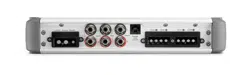
PREAMP OUTPUTS
The MHD600/4 incorporates a pass-through
preamp output section, so that additional
amplifiers can easily be connected to the same
signal(s) feeding the MHD600/4. These preamp
output signals are accessible via a stereo pair
of RCA-type jacks, labeled “Preouts”, on the
Connection Panel.
Rear Preouts
Remote
Level
Control
Front
Inputs
L
R
L
R
+12 VDC Ground Remote
The term “pass-through” refers to the fact that
the Preamp Output signals are not affected by
any crossover filter or input sensitivity setting
selected on the MHD600/4 (if the input signal
is full-range, the Preamp Output will be full-
range). These preamp output signals are buffered
to prevent noise and are always preamp level,
regardless of the level of signals feeding the
MHD600/4’s inputs.
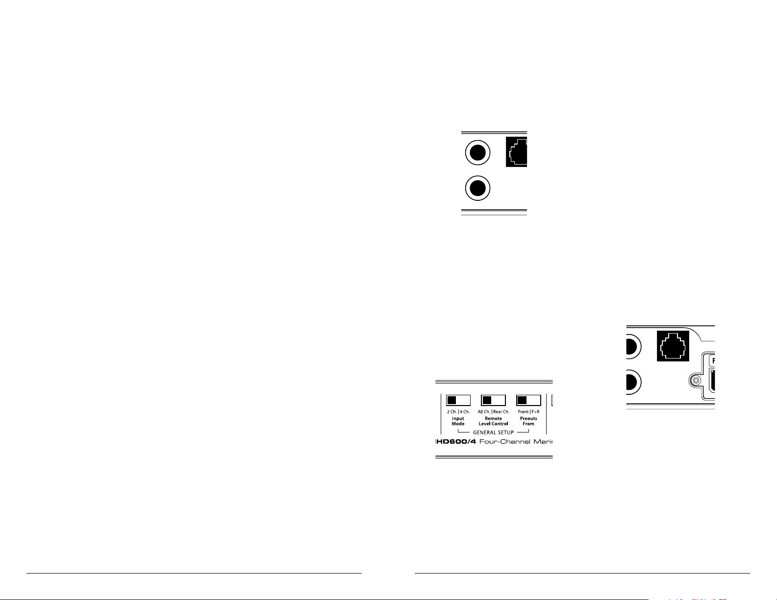
The pass-through Preamp Outputs can be
configured two different ways using the switch
labeled “Preouts From” in the “General Setup”
section of the Control Panel.
1) “Front”: The preamp output delivers the same
signal that is connected to the MHD600/4’s
“Front Inputs”. This mode is useful for feeding
a subwoofer amplifier when the MHD600/4
is being used to drive front and rear speaker
systems. In this mode, the preamp output level
will track with the signal level of the front input
signals, allowing the user to fade the rear channels
in and out, without affecting the subwoofer level.
3) “F+R” (Front + Rear): This mode delivers a
sum of the signals being fed to the “Front
Inputs” and the “Rear Inputs” of the
amplifier. When the MHD600/4 is being used
to drive front and rear speaker systems, this
preamp output mode will deliver a summed
front/rear signal to the subwoofer amplifier,
while permitting fading of the front and rear
speaker systems from the source unit.
REMOTE LEVEL CONTROL OPTIONAL
With the addition of the optional Remote Level
Control (HD-RLC), you can control the volume
of one or both channel pairs of the MHD600/4
from the cockpit. This is useful for subwoofer
level control or even as a master volume control
for the system.
The HD-RLC connects to the jack labeled
“Remote Level Control” on the Connection
Panel of the amplifier using a standard telephone
cable (supplied with the HD-RLC).
If desired, multiple MHD amplifiers can be
controlled from a single HD-RLC controller
using a simple phone line “splitter” and multiple
phone cables (not supplied).
Rear Preouts
Remote
Level
Control
Front
Inputs
L
R
L
R
+12 VDC Ground Remote
BIAMPLIFIED SYSTEMS
Bi-amplified systems are defined as systems
in which separate amplifier channels drive low-
frequency (LF) and high-frequency (HF) speakers
and are separately filtered to send appropriate
frequency ranges to each speaker system.
The most common application of
bi-amplification in mobile audio is to drive a
subwoofer system from one or more amplifiers or
channels and component speakers from separate
amplifiers or channels.
The MHD600/4 can be configured to drive a
bi-amplified system by itself or with a separate
subwoofer amplifier.
Bi-Amplified System with one MHD600/4
In this configuration, the “Rear” channels
of the MHD600/4 will drive subwoofers
(stereo 150W x 2 or bridged 300W x 1) with
low-pass filtering. The “Front” channels
will drive component speakers in stereo
(150W x 2) with high-pass filtering.
Crossover Setup for Bi-Amplified System
with one MHD600/4:
Once the input sections have been configured
appropriately, go to the “Rear Channel Controls”
Section. Select “LP” (low-pass) on the “Filter
Mode” switch and “12dB” or “24dB” on the
“Filter Slope” switch and an appropriate “Filter
Freq.” (80-90 Hz is a good starting point).
Next, turn your attention to the “Front
Channel Controls” Section. and select “HP”
(high-pass) on the “Filter Mode” switch and
“12dB” or “24dB” on the “Filter Slope”
switch and an appropriate “Filter Freq.”
(again, 80-90 Hz is a good starting point).
After proper adjustment of the Front and
Rear channel “Input Range” and “Input
Sens.” controls using the method shown
in Appendix C (pages 18, 19), you can
fine tune filter frequencies and slopes and
attenuate either pair of channels to achieve
proper balance. For precise filter frequency
information refer to Appendix B (page 18).
Bi-Amplified System with one
MHD600/4 in four-channel mode and
a separate subwoofer amplifier
This configuration requires that the separate
subwoofer amplifier has a built-in low-pass
filter. In this configuration, the “Front”
channels of the MHD600/4 will drive front
component speakers (stereo 150W x 2) with
high-pass filtering. The “Rear” channels
will drive rear component speakers in stereo
(150W x 2) with high-pass filtering.
The separate subwoofer amplifier will drive the
subwoofer system with low-pass filtering (select a
filter frequency of 80-90 Hz to start). The inputs
of the subwoofer amplifier can be fed from the
MHD600/4’s preamp output or from a dedicated
subwoofer output on the source unit.
Crossover Setup for Bi-Amplified System with one
MHD600/4 and a separate subwoofer amplifier:
Once the input and preamp output sections
have been configured appropriately, go to the
“Front Channel Controls” Section. Select “HP”
(high-pass) on the “Filter Mode” switch and
“12dB” or “24dB” on the “Filter Slope” switch
and an appropriate “Filter Freq.” (80-90 Hz is a
good starting point).
Next, turn your attention to the “Rear
Channel Controls” Section and select “HP”
(high-pass) on the “Filter Mode” switch and
“12dB” or “24dB” on the “Filter Slope” switch
and an appropriate “Filter Freq.” (again, 80-90 Hz
is a good starting point).
After proper adjustment of the MHD600/4’s
and the subwoofer amplifier’s “Input Range” and
“Input Sens.”, you can fine tune filter frequencies
and slopes and attenuate either pair of channels to
achieve proper balance. For proper adjustment of
the “Input Sens.” controls of the MHD600/4 use
the method shown in Appendix C (pages 18, 19).
For precise filter frequency information for the
MHD600/4 refer to Appendix B (pages 18). Refer
to the subwoofer amplifier owner’s manual for its
proper adjustment levels.
Loading ...
Loading ...
Loading ...