Loading ...
Loading ...
Loading ...
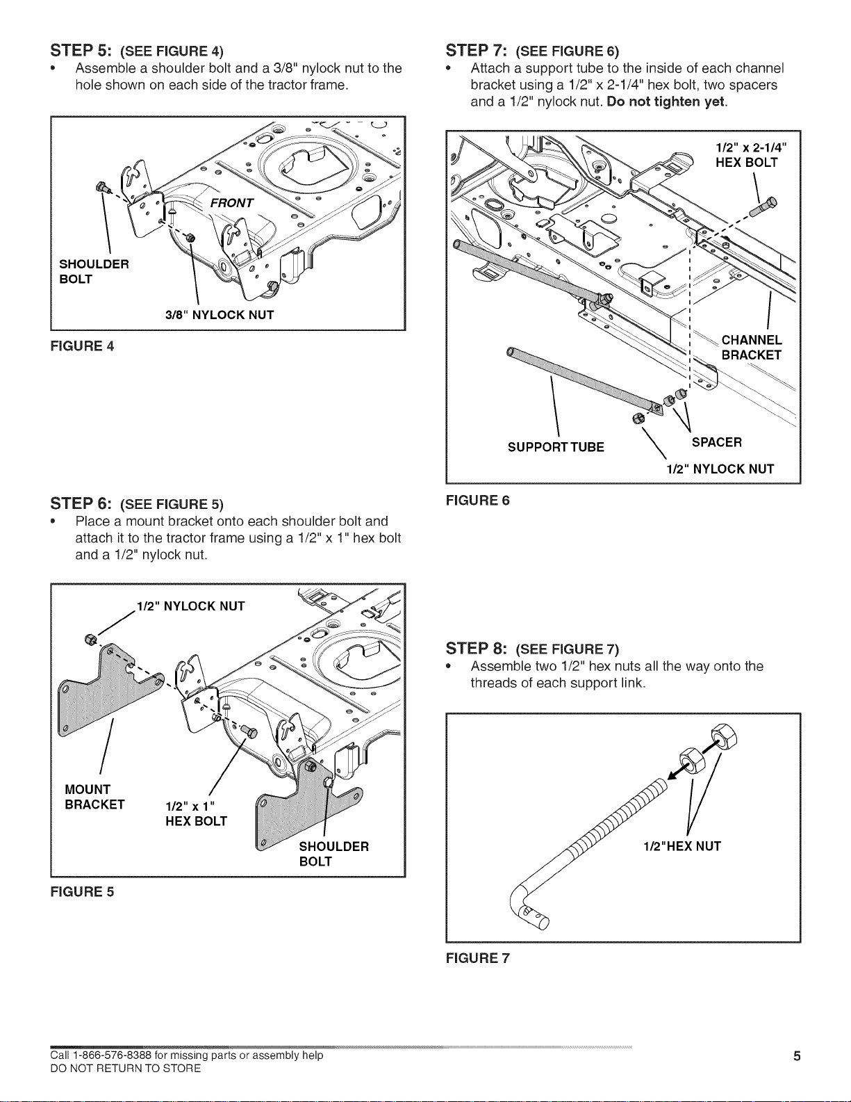
STEP 5: (SEE FIGURE4)
* Assemble a shoulder bolt and a 3/8" nylock nut to the
hole shown on each side of the tractor frame.
SHOULDER
BOLT
FIGURE 4
3_"NYLOCK NUT
STEP 6: (SEE FIGURE 5)
, Place a mount bracket onto each shoulder bolt and
attach it to the tractor frame using a 1/2" x 1" hex bolt
and a 1/2" nylock nut.
STEP 7: (SEE FIGURE 6)
, Attach a support tube to the inside of each channel
bracket using a 1/2" x 2-1/4" hex bolt, two spacers
and a 1/2" nylock nut. Do not tighten yet.
1/2" x 2-1/4"
HEX BOLT
s
_ :_ CHANNEL
_:_BRACKET
/ . \1
SUPPORTTUBE
SPACER
1/2" NYLOCK NUT
FIGURE 6
MOUNT
BRACKET
FIGURE 5
STEP 8: (SEE FIGURE 7)
* Assemble two 1/2" hex nuts all the way onto the
threads of each support link.
1/2
FIGURE 7
Call 1-888-578-8388 for missing parts or assembly help 5
DO NOT RETURN TO STORE
Loading ...
Loading ...
Loading ...