Loading ...
Loading ...
Loading ...
5
ASSEMBLY INSTRUCTIONS
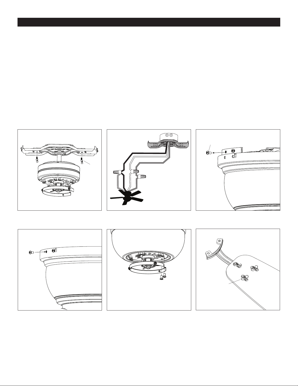
4. Reinstall the previously removed bracket screws to secure the lower mounting bracket to the upper mounting bracket (Figure 2.4).
5. Connect the household supply wires and fan wires according to the diagram (Figure 2.5) and these steps:
a) Connect the green wire from the lower mounting bracket to the bare/green (ground) supply wire. b) Connect the white
wire from the fan to the white (neutral) supply wire. c) Connect the black and blue wires from the fan to the black (hot) supply
wires. Note: If there’s a second hot wire coming from the outlet box, connect it to the blue (light power) fan wire for separate
light and fan control. d) Secure all connections with wire connectors.
6. Temporarily lift the motor housing to the mounting bracket to determine which two motor housing screws in the sides of
the upper mounting bracket align with the slotted holes in the top edge of the motor housing. Partially loosen the two motor
housing mounting screws that a light with the slotted holes. Remove the other two motor housing screws from the opposite
sides of the mounting bracket (Figure 2.6).
7. Slide the motor housing up over the motor, aligning the slotted holes in the motor housing wit the two loosened motor
housing mounting screws in the upper mouting bracket. Twist the motor housing clockwise to lock. Then, reinstall the two
previously-removed motor housing screws and securely tighten all four screws (Figure 2.7).
8. Remove the ten motor screws from the underside of the motor and set aside for blade arm assembly (Figure 2.8).
9. The blades attach to the blade arms using the Fast Attach™ system. Align each twist lock connector in the direction of its
corresponding hole in the blade. Place the blade over the twist lock connectors. Rotate each twist lock connector so it is
perpendicular to the hole in the blade (Figura 2.9). Repeat for remaining blades.
Black (Hot)
White (Neutral)
Bare/Green (Ground)
Black
Blue
White
Green
Figure 2.4
Figure 2.7
Wire Connector
WARNING: Do NOT wire the
fan motor to a variable-speed
(dimmer) wall control.
Bracket
Screws
Motor Housing
Screw
Motor Housing
Screw
Motor
Screws
Figure 2.5
Figure 2.8
Figure 2.6
Figure 2.9
Twist Lock
Connector
Blade Arm
Blade
Loading ...
Loading ...
Loading ...