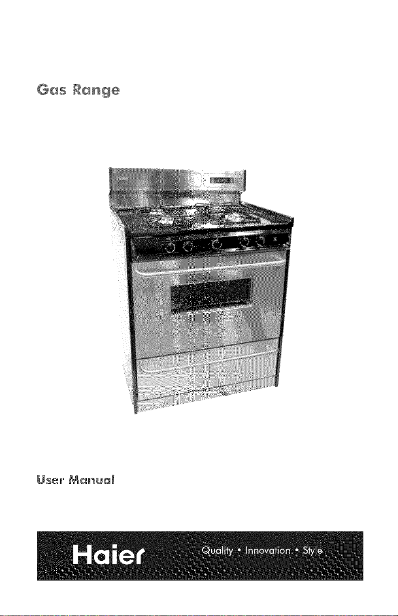
Gas Ramge
User Manua_
This manual contains information for:
• Important Safeguards
•Installation
•Use and Care
Certain ranges come equipped with special features. Determine from a study of
your range which of the instructions given in this booklet pertain to your range.
This booklet gives valuable instructions covering the installation, adjustment and
use of your range.
HOW TO OBTAIN SERVICE AND/OR PARTS
When your range does not operate in accordance with the instructions in the
manual, you should contact the dealer in the immediate vicinity for service. Or,
the purchaser may contact the service organization noted on the warranty.
IMPORTANT
TO THE OWNER OF THE RANGE: Retain this owner's manual for future reference.
TO THE INSTALLER: Leave this owner's manual with the range.
Read and Save These Instructions

Range
Record in the space provided below the Model No. and Serial No. of this appliance. These
numbers are found on the serial plate located below the lift-up cooktop.
Model No. Type Number
Serial No. Purchase Date
Record these numbers for future use.
IMPORTANT: Keep a copy of your bill of sale. The date on the bill establishes the
warranty period should service be required. If service is performed, it is in your best
interest to obtain and keep all receipts.
PLEASE DO THIS NOW[
The PRODUCT REGISTRATION CARD should be filled in completely, signed and
returned. This information will register your product and help us to serve you quickly in
the future if necessary.
Contents
hnportant Safeguards ................................................... 4-8
Energy Saving ldeas ...................................................... 8
Installation Instructions ................................................ 9-10
Backguard Installation ................................................... 11
Wall Clearances ........................................................ 12
Alignments and Adjustments ........................................... 13-20
Operation of Range ................................................... 21-23
Broiling .............................................................. 23
Optional Equipment .................................................. 24-25
Cleaning the Range ................................................... 26-27
Lift-Off Doors ......................................................... 28
Trouble Shooting Guide .................................................. 29
Wiring Diagrams .................................................... 30-31
Note: For warranty and service information, please see back cover of this manual.
I
[A'-WARNING'ftheinformationinthismanua,isnotfo,,owedexact,,,,,[
afire or explosion may result causing property damage,
personal injury or death.
Do not store or use gasoline or other flammable vapors and liquids in
the vicinity of this or any other appliance.
WHAT TO DO IFYOU SMELL GAS:
•Do not try to light any appliance.
•Do not touch any electrical switch; do not use any phone in your
building.
•Immediately call your gas supplier from a neighbor's phone. Follow
the gas supplier's instructions.
•If you cannot reach your gas supplier, call the fire department.
Installation and service must be performed by aqualified installer,
service agency or the gas supplier.
READ ALL IMPORTANT SAFEGUARDS AND ALL
INSTRUCTIONS BEFORE USING THE APPLIANCE.
Remove all tape and packaging wrap before using the oven. lfany glue remains, touch
the residue with the sticky side of the tape already removed, or use a cloth soaked with
rubbing alcohol. Use caution because rubbing alcohol is flammable. Rinse with warm
water and wipe dry.
Destroy the carton and plastic bags after the range is unpacked. Children should not
use packaging material for play. Cartons covered with rugs, bedspreads, or plastic sheets
can become air-tight chambers. Remove all staples from the carton. Staples can cause
severe cuts and destroy finishes if they come in contact with other appliances or furniture.
Be safety conscious. The preparation of food in an oven requires temperatures that could cause
severe burns. Before using this new appliance, carefully read and follow all instructions.
[AWARNING]
The California Safe Drinking Water and Toxic Enforcement Act of 1986
(Proposition 65) requires the Governor of California to publish a list of
substances known to the State of California to cause cancer or reproductive
harm. In addition, businesses must warn customers of potential exposure to
such substances.
Users of this appliance are hereby warned that the burning of gas can result in low level
exposure to some of the listed substances, including formaldehyde, benzene, soot and carbon
monoxide. This is caused primarily fi'om the incomplete combustion of natural gas or LP fuel.
Properly adjusted burners will minimize incomplete combustion. Exposure to these
substances can also be minimized by properly venting the burners by opening a window or
using a ventilating hood or fan.
Notice: Never keep pet birds in the kitchen. Birds have a very sensitive respiratory system.
Fumes released during the self-cleaning cycle, overheated cooking oil, tat, margarine or
overheated non-stick cookware may be harmful or fatal to birds.
PROPER INSTALLATION: Be sure your appliance is properly installed and grounded by
a qualified technician in accordance with the National Fuel Gas Code ANSI Z223.1-1atest
edition, and the National Electrical (:ode ANS1i2gFPANo. 70-latest edition. Install only per
installation instructions provided in the literature package for this range. Be sure leveling legs
are in place at the bottom corners of the range. If necessary, raise or lower the leveling legs at
the base of the range by turning clockwise or counterclockwise to insure a level range.
Ask your dealer to reconamend a qualified technician and an authorized repair service.
Have the technician familiarize you with the locations of the manual gas shut off valve and
gas meter in the event it is necessary to shut off" gas supply to the unit during an
emergency.
["JlAWARN[NG[ The following situations may cause serious bodily harm, death or
property damage.
• TO REDUCE THE RISK OF TIPPING OF THE RANGE, THE RANGE MUST BE SECURED
BY A PROPERLY INSTALLED ANTI-TIP BRACKET PROVIDED WITH THE RANGE. TO
CHECK IF THE DEVICE IS INSTALLED AND ENGAGED PROPERLY, CAREFULLY TIP
THE RANGE FOR\\ARD. THE ANTI-TIP DEVICE SHOULD ENGAGE AND PREVENT THE
RANGE FROM TIPPING OVER. REFER TO THE INSTALLATION INSTRUCTIONS
PACKAGED WITH THE ANTI-TIP BRACKET FOR PROPER ANTI-TIP BRACKET
INSTALLATION.
•Never leave children alone or unattended in the area where an appliance is in use.
They should never be allowed to sit or stand on any part of the appliance. Never leave
the oven door open when the range is unattended.
•Do not store items of interest to children in the cabinets above a range or on the
backguard of a range. Children climbing on the range to reach the items coukt be
seriously injured.
IMPORTANT SAFEGUARDS, Continued
• Do not allow children to climb or play around the range. The weight of a child on an
open oven door may cause the range to tip, resulting in serious burns or other injury.
•USER SERVICING: Do not repair or replace any part of the appliance unless
specifically recommended in this mvner's guide. All other servicing should be done
only by a qualified technician. This will reduce the risk of personal injury and damage
to the range.
•Storage in or on appliance: Flammable materials should not be stored in an oven, near
surface burners or in the broiler section. This includes paper, plastic and cloth items,
such as cookbooks, plasticware and towels, as well as flammable liquids. Do not use the
oven for storage. Do not store explosives, such as aerosol cans, on or near the range.
• Remove the oven door from any unused range if it is to be stored or discarded.
• Stepping, leaning or sitting on the doors or broiler section of this range can result
in serious injuries and cause damage to the range.
l"JlACAUTIONIThefollowing situations could cause bodily injury or property
damage.
•DO NOT TOUCH SURFACE BURNERS, AREAS NEAR THESE BURNERS,
OVEN BURNERS OR INTERIOR SURFACES OF THE OVEN . Both surface
burners and oven burners may be hot even though the flame is not visible. Areas near
surface burners may become hot enough to cause burns. During and after use, do not
touch, or let clothing or other flammable materials touch these areas until they have had
sufficient time to cool. Among these areas are the cooktop, surfaces facing the cooktop,
the oven vent openings and surfaces near these openings, oven door and windows.
[_GJ|'WARNIN`[ .NEVER use this appliance as aspace heater to heat or warm the
room. Doing so may result in carbon monoxide poisoning and overheating
of the oven.
• Wear proper apparel. Loose fitting or hanging garments should never be worn while
using the appliance. Do not let clothing or other flammable materials contact surface
burners or interior surfaces of the oven until they have had sufficient time to cool.
• Never modify or alter the construction of the range. Do not remove leveling legs,
panels, wire covers, anti-tip brackets or any other permanent part of the product.
•When heating fat or grease, watch it closely. Fat or grease may catch fire if allowed to
become too hot.
• Do not use water or flour on grease fires. Smother the fire with a pan lid, baking soda
or use a dry chemical or foam-type extinguisher.
•Operation of Surface Burners. When the burners are operated for the first time, a small
amount of smoke may be generated due to tape residue or manufacturing lubrication.
THIS IS NOT DANGEROUS. Operate the burners for about five minutes to rid the
burners of this material before cooking. 5

IMPORTANT SAFEGUARDS, Continued
•Use only dry potholders. Wet or damp potholders on hot surfaces could result in burns
from steam. Do not let the potholder touch hot heating areas. Do not use a towel or other
bulky cloth instead of a potholder.
• Use proper flame size. Adjust flame size so it does not extend beyond the edge of the
utensil. The use of undersized utensils will expose a portion of the burner flame and may
result in severe burns or direct contact and ignition of clothing. Also, proper relationship
of utensil to burner will improve efficiency.
]'WARNING=. coveran,'s,ots,bo,esorpassages,ntbeovenbottomor
cover an entire rack with materials such as aluminum foil. Doing so
blocks air flow through the oven and may cause carbon monoxide
poisoning. Aluminum foil linings may also trap heat, causing a fire hazard. Refer to the
cleaning section of this manual for more information on the use of aluminum foil.
• Placement of oven racks: Always place an oven rack in the desired location while the
oven is cool. lfa rack must be moved when the oven is hot, use potholders and grasp the
rack with both hands to reposition. Do not let potholders contact hot oven walls. Remove
all utensils from the rack before moving.
• Do not heat unopened food containers. Build-up of pressure may cause the container
to burst and result in injury.
• Keep the oven vent duct unobstructed. The oven vent is located along the bottom of
the backguard. Touching the surfaces in the vent area when the oven is being operated
may cause severe burns. Also, do not place plastic or heat-sensitive items on or near the
oven vents. These items could melt or ignite.
The range requires fresh air for proper burner combustion. Do not block the flow of air
around the base or beneath the lower front panel of the range.
• Use care when opening oven door: Stand to the side of the oven when opening the
oven door. Slowly open the door to allow hot air or steam to escape before removing or
replacing food.
• Know which knob controls each burner. Place a pan of food on the burner before
turning it on, and turn the burner off before removing the pan.
Always turn to the full LITE position when igniting top burners. Then adjust the flame
size so it does not extend beyond the edge of the utensil.
•Utensil handles should be turned inward and not extend over adjacent surface
burners. To reduce the risk of burns, ignition of flammable materials, and spillage due
to unintentional contact with the utensil, the handle of a utensil should be positioned so
that it is turned inward, and does not extend over adjacent surface burners.
• Never leave the surface burners unattended. Boilovers may cause smoking, greasy
spillovers may catch fire or a pan which has boiled dry may melt.
IMPORTANT SAFEGUARDS, Continued
•Do not place hands between the spring tension hinge and the oven door frame when
you are removing the oven door. You could pinch your fingers.
• Do not use the broiler pan without its insert. The broiler pan and its insert allow
dripping fat or grease to drain find be kept away fl'om the high heat of the broiler. Do not
cover the insert with foil. Exposed fat or grease could ignite.
• Do not touch ahot oven light bulb with adamp cloth. A hot oven light bulb could
break it touched with a damp cloth. Disconnect the electrical service cord or shut offthe
power to the oven before removing and replacing the bulb.
• Allow parts to cool to room temperature before touching or remm4ng them from the range.
When a surfiice burner is first turned off, the burner find grate are hot enough to cause burns.
• Clean the range regularly to keep all parts free of fat or grease which could catch
fire. Pay particular attention to the area underneath each surface burner. Exhaust fan
ventilating hoods and grease filters should be clean. Do not allow flit or grease to
accumulate. Greasy deposits in the fan could catch fire. Refer to the hood
manufacturer's instructions for cleaning.
•Do not use a "cyclonic" range hood with this product. Some range hoods circulate air
by blowing downward toward the range top then drawing the air back up into the hood.
This creates a "cyclonic" air wash that is designed for electric ranges only. A "cyclonic"
hood may cause the burners of a gas range to operate improperly.
• Glazed cooking utensils: Only certain types of glass, glass/ceramic, ceramic, earthenware,
or other glazed utensils are suitable for rangetop service without breaking, due to the sudden
change in temperature. Check the manufacturer's recommendations for rangetop use.
• Do not place plastic salt and pepper shakers, spoon holders or plastic wrappings on
top of the range. These items could melt or ignite. Potholders, towels or wooden spoons
could catch fire if place too close to the flame.
• Do not use a wok equipped with a metal ring that extends beyond the burner.
Because this ring traps heat, the burner and grate could be damaged. Also, the burner may
not work properly, creating a carbon monoxide level above current health standards.
• Do not clean the oven door gasket. The door gasket is essential for a good seal. Care
should be taken not to rub, damage or move the gasket.
• Flexible Connectors: If the gas range/oven is connected to a gas supply with a metal
flexible connector, move the range/oven with CAUTION for service or cleaning.
Flexible connectors are not intended for repeated bending. Do not allow cleaners to
make contact with flexible connectors.
The connector and its fittings are designed for use only on the original installation
and are not to be reused for another appliance or at another location. Connectors
must comply with ANSI Z21.24.
•It'sgoodpracticeforeachhousehold to have an appropriate fire extinguisher for
use in the event of a house fire.
•Disconnect the range from electrical supply before attempting to service or move it.
I NOTE: The instructions appearing in this owner's guide are not meant to cover every I
I
possible condition and situation that may occur. Colnmon sense and caution must be I
practiced when operating and maintaining any appliance.
On sealed burner models never attempt to operate the surface
IIAWARNINGIburners without the cooktnp, burner caps, and ignition ,,rire_ firmly [
in place. There is a risk of fire and/or explosion _hich could result in
personal injury or property loss.
ENERGY-SAVING IDEAS
Surface Cooking
Use lids when surthce cooking. A lid traps steam and uses it to speed up the cooking
process. If you have a pressure cooker or vegetable steamer, use it. You'll waste fewer
vitamins, save time and cut energy costs.
Use medium-weight, flat bottomed pans that match the flame size. Choose pans made of
metals that conduct heat well.
When cooking on a surface burner, use as little water as possible to reduce cooking time.
Oven Cooking
Preheat the oven only when a recipe tells you. Put roasts and casseroles into a cold oven;
then turn on the oven.
Opening the oven door often to check on foods wastes energy.
Use the oven to prepare complete meals. For instance, start a roast, add vegetables when
the meat is half-cooked, and then warm rolls or dessert after the main dishes are cooked.
Thaw frozen foods before cooking. Thawed food requires less cooking energy than frozen
food.
Make it a habit to turn the oven off bet'ore removing the cooked food.
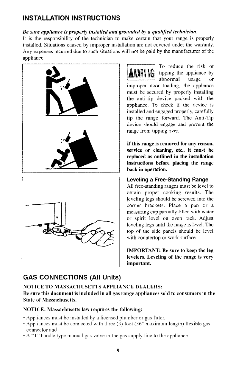
INSTALLATION INSTRUCTIONS
Be sure appliance is properly installed and grounded by a qualified technician.
It is the responsibility of the technician to make certain that your range is properly
installed. Situations caused by improper installation are not covered under the warranty.
Any expenses incurred due to such situations will not be paid by the manufacturer of the
appliance.
, WARNINGTo reduce the risk oftipping the appliance by
abnormal usage or
improper door loading, the appliance
must be secured by properly installing
the anti-tip device packed with the
appliance. To check if the device is
installed and engaged properly, carefully
tip the range forward. The Anti-Tip
device should engage and prevent the
range from tipping over.
If this range is removed for any reason,
service or cleaning, etc., it must be
replaced as outlined in the installation
instructions before placing the range
back in operation.
Leveling a Free-Standing Range
All free-standing ranges must be level to
obtain proper cooking results. The
leveling legs should be screwed into the
corner brackets, Place a pan or a
measuring cup partially filled with water
or spirit level on oven rack, Adjust
leveling legs until the range is level. The
top of the side panels should be level
with countertop or work surface.
IMPORTANT: Be sure to keep the leg
levelers. Leveling of the range is very
important.
GAS CONNECTIONS (All Units)
NOTICE TO MASSACHUSETTS APPLIANCE DEALERS:
Be sure this document is included in all gas range appliances sold to consumers in the
State of Massachusetts.
NOTICE: Massachusetts law requires the following:
•Appliances must be installed by a licensed plumber or gas fitter.
• Appliances must be connected with three (3) foot (36" maximum length) flexible gas
connector and
• A "T" handle type manual gas valve in the gas supply line to the appliance.
GAS CONNECTIONS (All Units), Continued
Have the dealer where you purchase your new range install it or have him recommend a
qualified installer. Installation must conforna with local codes, in the absence of local
codes, the installation must conform with the National Fuel Gas Code, ANSI Z223.1-
Latest Edition in the U.S.A. or the CANiCGA B149.1 or .2 Installation Codes in Canada.
The range should be connected to the supply line with li2-inch black iron pipe or a
certified flexible type stove connector. To prevent gas leaks, put an approved sealing
compound, which is resistant to liquefied petroleum gases, on all threaded connections.
lnq)ortant." Do not apply pressure directly to the range manifold pipe when tightening
supply connections. The manifold pipe should be held securely at the pressure regulator
to prevent twisting. Hold the pressure regulator with a wrench during the tightening of the
connection, or the manifold pipe may be twisted and split, and cause a dangerous leak.
The installation of ranges designed for manufactured (mobile) home installation must
conform with the Manufactured Construction and Safety, Title 24 CFR, Part 3280,
[formerly the Federal standard for Mobile Home Construction and Safety, Title 24, HUD
(Part 280)] in the U.S.A. or C.S.A. Standard CAN/CGA Z240.4.2 in Canada or, when such
standards are not applicable with local codes.
The installation of ranges designed for recreational vehicle installation must conform with
state or other codes or, in the absence of such codes, with the standard for recreational
vehicles. ANSI A119.2.2 1982 in the U.S.A. or CANiCGA Z240.4.2 in Canada.
The installation of appliances designed for recreational park trailers must conform with
state or other codes or, in the absence of such codes, with the standard for recreational
park trailers, ANSI A119.5.
Note." Check all piping connections in the unit for leaks. Never use an open flame to check
for gas leaks. Use a soap solution. It is not impossible for connections made at the factory
to leak, due to vibration encountered in transportation. Make certain you have checked
them all, and repair any connections that leak.
The appliance and its individual shut-off valve must be disconnected from the gas supply
piping system during any pressure testing of that system at test pressures in excess of I/2
psig.
The appliance must be isolated from the gas supply piping system by closing its individual
manual shut-off valve during any pressure testing of the gas supply piping system at test
pressures equal to or less than 1/2 psig.
Electrical Connections
All electrical wiring and attachments are 60-cycle, 120 volts, 15 amp max. Your range is
grounded with a three-conductor (three-prong plug) supply cord which will ground the
range when plugged into a GROUNDED wall receptacle. If the backguard of the range
has a clock or light, connect the cord from the backguard into the special terminal block
located at the top of the main back directly under the backguard supply cord.
The appliance must be electrically grounded when installed in accordance with local
codes, or in the absence of local codes, with the National Electrical Code, ANSIiNFPA
No. 70 Latest Edition in the U.S.A. or the Canadian Electrical Code, C22.1; Part 1 in
Canada, if an external electrical source is utilized.
10
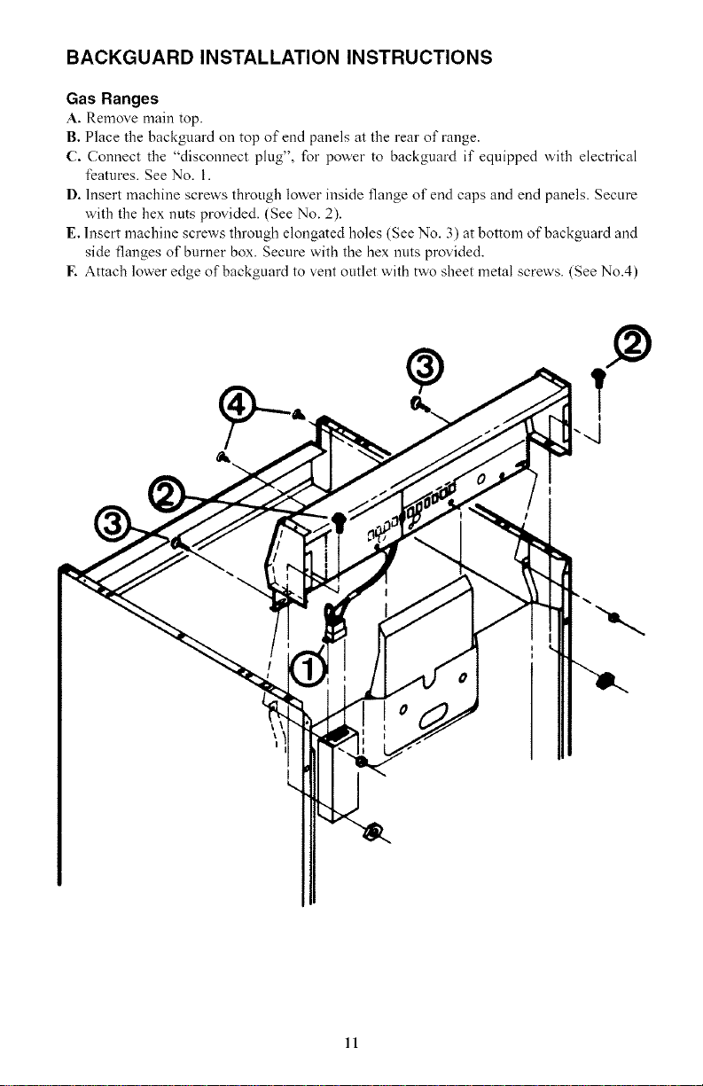
BACKGUARD INSTALLATION INSTRUCTIONS
Gas Ranges
A. Remove main top.
B. Place the backguard on top of end panels at the rear of range.
C. Connect the "disconnect plug", for power to backguard if equipped with electrical
features. See No. 1.
D. Insert machine screws through lower inside flange of end caps and end panels. Secure
with the hex nuts provided. (See No. 2).
E. Insert machine screws through elongated holes (See No. 3) at bottom of backguard and
side flanges of burner box. Secure with the hex nuts provided.
E Attach lower edge of backguard to vent outlet with two sheet metal screws. (See No.4)
11
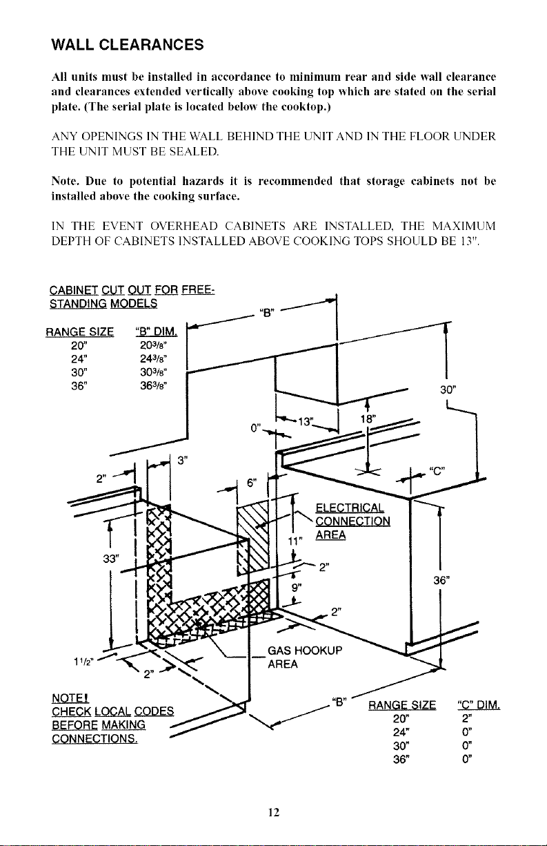
WALL CLEARANCES
All units must be installed in accordance to minimum rear and side wall clearance
and clearances extended vertically above cooking top which are stated on the serial
plate. (The serial plate is located below the cooktop.)
ANY OPENINGS 1N THE WALL BEHIND THE UNIT AND 1N THE FLOOR UNDER
THE [3NIT MUST BE SEALED.
Note. Due to potential hazards it is recommended that storage cabinets not be
installed above the cooking surface.
1N THE EVENT OVERHEAD CABINETS ARE INSTALLED, THE MAXIMUM
DEPTH OF CABINETS INSTALLED ABOVE COOKING TOPS SHOULD BE 13".
RANGE SIZE "[3" DIM.
20" 203/s"
24" 243/8"
30" 303/8"
36" 363/s"
g_J_N_E_Y_C_U_Z_O__LffF_O_BFR_BS_
_t_LOJ25L_
_r 36"
GAS HOOKUP _ _-I
mAREA
"B" RANGE SIZE
20" 2"
24" 0"
30" 0"
36" 0"
12
ALIGNMENTS AND ADJUSTMENTS
Installation
It is the responsibility of the installer to make certain that the range is properly adjusted
at the time of installation. Situations caused by improper adjustments or improper
installation are not covered under the warranty. Any expenses incurred due to such
situations will not be paid by the manufacturer of the appliance.
Gas Range Conversion and Adjustment Guide
The range will either be set for use with Liquefied Petroleum (LP) or Natural Gas. The
factory setting is indicated on the serial plate. When set for Natural Gas operation, the
pressure regulator will regulate the pressure to 4 inches water column. When set for LP
Gas operation, the pressure regulator will regulate the gas to 10 inches water column
pressure.
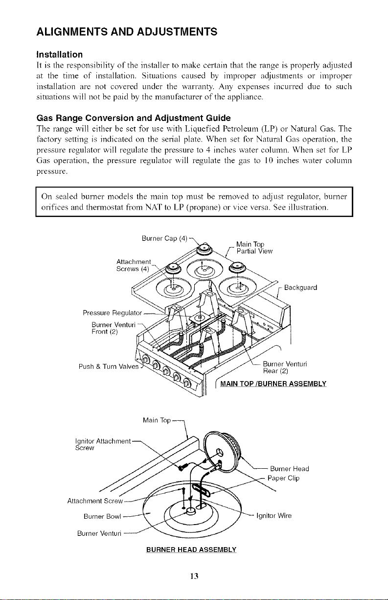
Ion sealed burner models the main top must be removed to adjust regulator, burner I
I
orifices and thermostat fl'om NAT to LP (propane) or vice versa. See illustration. I
Burner
Attachment
Screws (4)
Main Top
Partial View
Jard
Pressure Regt
Front(2)
Rear (2)
rvlAIN TOP/BURNER ASSEMBLY
Main To
Ignitor Attachment
Screw
Attachment
Burner
Burner Venturi
BURNER HEAD ASSEMBLY
Head
- Paper Clip
niter Wire
13
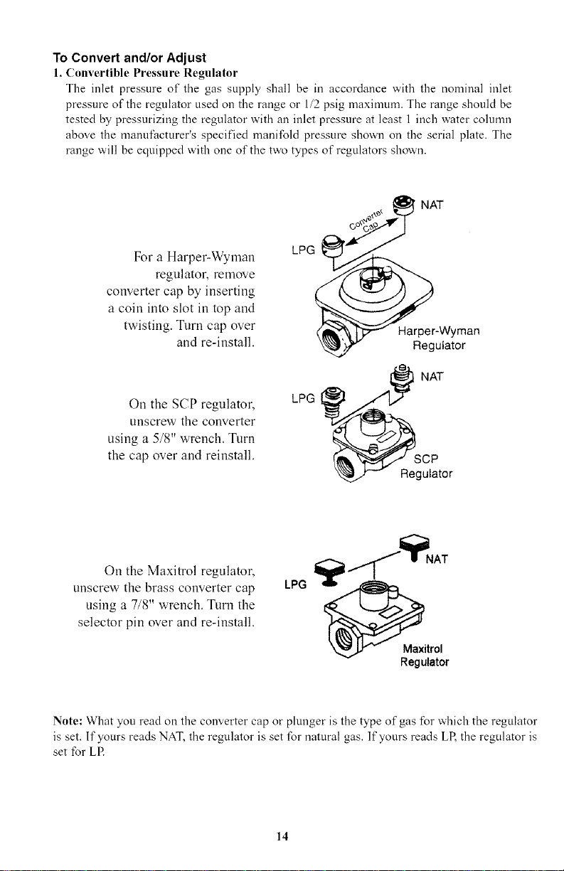
To Convert and/or Adjust
1. Convertible Pressure Regulator
The inlet pressure of the gas supply shall be in accordance with the nominal inlet
pressure of the regulator used on the range or 1/2 psig maximum. The range should be
tested by pressurizing the regulator with an inlet pressure at least 1 inch water column
above the manufacturer's specified manifold pressure shown on the serial plate. The
range will be equipped with one of the two types of regulators shown.
NAT
For a Harper-Wyman
regulator, remove
converter cap by inserting
a coin into slot in top and
twisting. Turn cap over
and re-install.
On the SCP regulator,
unscrew the converter
using a 5/8" wrench. Turn
the cap over and reinstall.
LPG
LPG
Harper-Wyman
Regulator
NAT
SCP
Regulator
On the Maxitrol regulator,
unscrew the brass converter cap
using a 7/8" wrench. Turn the
selector pin over and re-install.
Maxitrol
Regulator
Note: What you read on the converter cap or plunger is the type of gas for which the regulator
is set. If yours reads NAT, the regulator is set for natural gas. If yours reads LP, the regulator is
set for LE
14
ALIGNMENTS AND ADJUSTMENTS, Continued
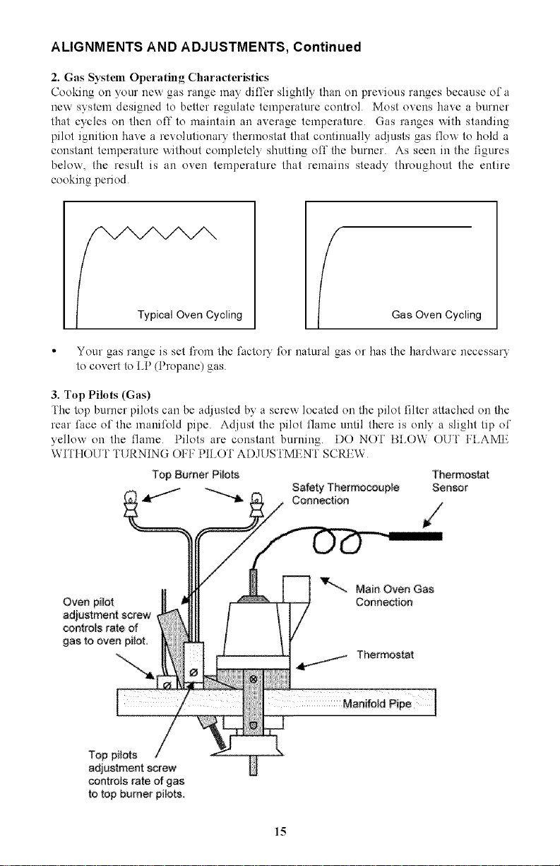
2. Gas Systeln Operating Characteristics
Cooking on your new gas range may differ slightly than on previous ranges because of a
new system designed to better regulate temperature control Most ovens have a burner
that cycles on then off to maintain an average temperature Gas ranges with standing
pilot ignition have a revolutionary thermostat that continually adjusts gas flow to hold a
constant temperature without completely shutting off the burner As seen in the figures
below, the result is an oven temperature that remains steady throughout the entire
cooking period
Typical Oven Cycling Gas Oven Cycling
• Your gas range is set from the l;acto15" for natural gas or has tile har&xare necessary
to covert to LP (Propane) gas
3. Top Pilots (Gas)
The top burner pilots can be adjusted by a screw located on the pilot filter attached on the
rear lhce of the manifold pipe Adjust the pilot flame until there is only a slight tip of
yellow on the flame Pilots are constant burning. DO NO'! BLOW OU'!' FLAMI_
WII'HOU i' TURNING ()I:F PILO'I ADJUS'I'MI_N'!' SCREW
Top Burner Pi_ots Thermostat
Safety ThermocouNe Sensor
Connection
Oven pi!ot
adjustment screw
controls rate of
gas to oven pilot,
'V-.._ Main Oven Gas
Connection
,j._ Thermostat
Top pilots
adjustment screw
controls rate of gas
to top burner pilots
15
ALIGNMENTS AND ADJUSTMENT, Continued
WARNING
Keep appliance area clear and free from combustible
materials, gasoline, and other flammable vapors and liquids.
Do not obstruct the flow of ah _that is necessary for
combustion and ventilation.
4. Top Burner Valves
Top burner valves have orifices that are dedicated to the type of l\lel to be used These
orifices are not adjustable '[hey must be changed completely to convert fiom one gas to
the other DO NOT DISCARD TttE UNUSED ORIFICES fhey should be saved in
order to convert the range back to its original fuel
When converting the gas valves, the minimum flame adjustment screw must be adjusted
through the center of the valve stem You will need a 3/32" flat blade screw driver to
make this adjustment itold the valve stem and turn the adjustment screw until the proper
flame of approximately 1/8" is obtained
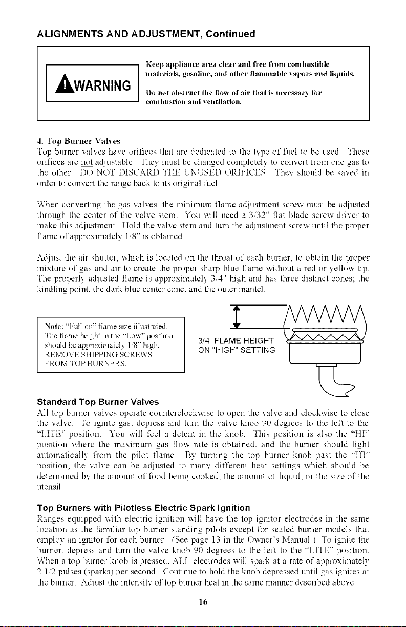
Adjust the air shutter, which is located on the throat of each burner, to obtain the proper
mixture of gas and air to create the proper sharp blue flame without a red or yellow tip
i'he properly adjusted flame is approximately 3/4" high and has three distinct cones; the
kindling point, the dark blue center cone, and the outer mantel
1' /WW A
Note: %'ull on" flame size illustrated Y { , , }
The flame height in the _Lox_" position 3/4" FLAME HEIGHT
should be approxinlately 1 8" high [j
REMOVE StIIPPING SCRE\\ S ON "HIGH" S ETTI NG
I,ROM "lOP BURNt RS 2>
Standard Top Burner Valves
All top burner valves operate counterclockxxise to open the valve and clockxxise to close
the valve To ignite gas depress and turn the valve knob 90 degrees to the left to the
LITE' position You will feel a detent in the knob This position is also the _[ti'
position where the maximum gas flow rate is obtained, and the burner should light
automatically l)om the pilot flame By turning the top burner knob past the _ti'
position the valve can be adjusted to many different heal settings xxhich should be
determined by the amount of food being cooked, the amount of liquid or the size of the
utensil
Top Burners with Pilotless Electric Spark Ignition
Ranges equipped xxith electric ignition xxill have the top ignitor electrodes in the same
location as the liuniliar top burner standing pilots except for sealed burner models that
employ an ignitor for each burner (See page 13 in the Oxxner's Manual) To ignite the
burner, depress and turn the valve knob 90 degrees to the left to the _ LITE" position
When a top burner knob is pressed, ALL electrodes will spark at a rate of approximately
2 1/2 pulses (sparks) per second Continue to hold the knob depressed until gas ignites at
the burner Adjust the intensity of top burner heat in the same manner described above
16
ALIGNMENTS AND ADJUSTMENT, Continued
in the event of a power lidlure, the top burners can be lit by holding a lighted match near
the burner head and turning the appropriate top burner knob to the %i I'E" position
Top Burner Height
Make sure the top burners are properly positioned 'l'he top of the burner head should be
level with the surl?ce of the main top '1'o check, lay a straight edge such as a 12-inch
ruler across the burner bowl opening The ruler should rest squarely on the top while in
contact with the burner head
if the burner is too high (make sure the burner is cool), push it down. Supply enough
lbrce with the pahn of you hand to accomplish this adjustment To raise, pull up on the
burner support at the center of the support
5. Oven Control (Thelanostat)
i'he oven control has a flame safety device built into tile body of the thermostat
Presence of a gas ignition source (pilot) is verified by a flame safety probe. 'l'his flame
safety probe actuates the internal safety device to allow gas into tile oven burner when tile
oven is turned on if there is a loss of gas ignition during operation, the flame safety
device will close offgas flow to the oven burner and pilot
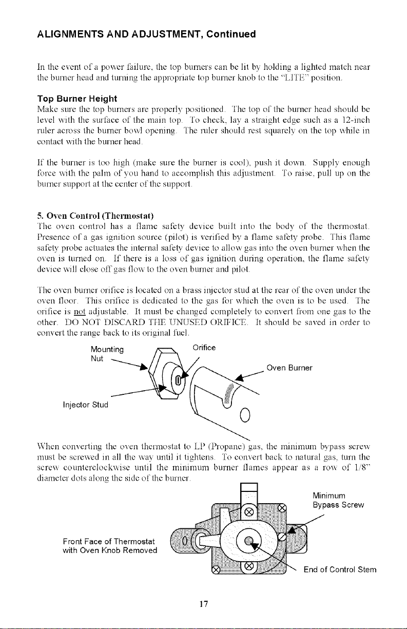
i'he oven burner orifice is located on a brass injector stud at tile rear of tile oven under the
oven floor 'iNs orifice is dedicated to tile gas for which tile oven is to be used 'l'he
orifice is not adjustable it must be changed completely to convert from one gas to tile
other DO NO'I' DISCARD 'I'HE UNUSED ORIFICE it should be saved in order to
convert tile range back to its original fuel
Mounting Orifice
Nut Oven Burner
Injector Stud 0
When converting tile oven thermostat to LP (Propane) gas, tile minimum bypass screw
must be screwed in all the way until it tightens '1'o convert back to natural gas, turn the
screw counterclockwise until the minimum burner flames appear as a row of 1/8'"
diameter dots along the side of the burner
Minimum
Bypass Screw
Front Face of Thermostat
with Oven Knob Removed
End of Control Stem
17
ALIGNMENTS AND ADJUSTMENT, Continued
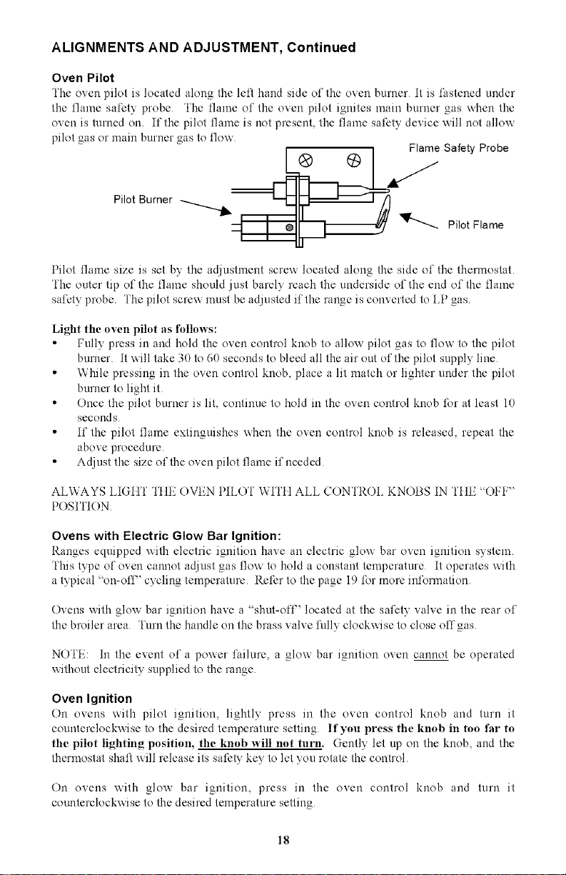
Oven Pilot
The oven pilot is located along tile left hand side of tile oven burner it is lhstened under
the flame safety probe 'I'he flame of tile oven pilot ignites main burner gas when the
oven is turned on. if tile pilot flame is not present, the flame safety device will not allow
pilot gas or main burner gas to flow
=_l___a _ Safety Probe
Pilot Burner _.............__ Pilot Flame
Pilot flame size is set by the adjustment screw located along the side of the thermostat
fhe outer tip of the flame should just barely reach the underside of the end of the flame
safety probe 'l'he pilot screw must be adjusted if the range is converted to LP gas
Light tile oven pilot as follows:
• Fully press in and hold the oven control knob to alloy, pilot gas to flow to the pilot
burner it will take 30 to 60 seconds to bleed all the air out of the pilot supply line
• While pressing in the oven control knob, place a lit match or lighter under the pilot
burner to light it
• Once the pilot burner is lit, continue to hold in the oven control knob for at least 10
secouds
• if tile pilot flame extinguishes when the oven control knob is released, repeat the
above procedure
• Adjust the size of the oven pilot flame if needed
ALWAYS LIGtlf file OVEN PILOI" Wli'tl ALL CON fROL KNOBS IN fItE ¢'OI:I:"
POSI I'ION
Ovens with Electric Glow Bar Ignition:
Ranges equipped with electric ignition have an electric glow bar oven ignition system.
This type of oven cannot adjust gas flow to hold a constant temperature it operates with
a typical on-off-' cycling temperature Refer to the page 19 for more information
Ovens with glo',x bar ignition have a * shut-ofl" located at the safety valve in the rear of
the broiler area i'urn the handle on the brass valve fully clockwise to close offgas
NO'I'E: in the event of a power lhilure, a glow bar ignition oven cannot be operated
without electricity supplied to the range
Oven Ignition
On ovens with pilot ignition, lightly press in the oven control knob and turn it
counterclockv, ise to the desired temperature setting If you press the knob in too thr to
the pilot lighting position, the knob ",,,'ill not turn. Gently let up on the knob, and the
thermostat shaft will release its safety key to let you rotate the control
On ovens with glov, bar ignition, press in the oven control knob and turn it
counterclockwise to the desired temperature setting
18
ALIGNMENTS AND ADJUSTMENT, Continued
Hot Oven Restart
if you turn off the oven but then decide to turn it back on before it has cooled to room
temperature, the burner may not light properly 'l'his is due to the thermostat still sensing
a heated oven and not allowing the maximmn gas flow rate into the burner Press in and
turn the oven control knob counter clockwise all the way to the ' BROIL" position to
relight the burner. After the burner has ignited, you may adjust the oven control to the
desired temperature
if tile oven burner does not ignite and maintain the flame, one of the following situations
may have occurred
1 The pilot burner has _one out. Relight the oven pilot
2 The pilot will not keep the flalne safe_" probe heated. Adjust the size of the pilot
flame Or, tile thermocouple connection at tile thermostat may need to be tightened
3 The flame safety probe nlay not be properly located. Locate the probe directly
over the pilot burner On spark ignition ovens, tile end of tile flame safety probe
must ve15" close to tile side of tile burner right in front of tile flame ports
4 The burner is not ill its proper position. Make sure the rear of tile burner is seated
on the iNector elbo_x and tile front is bolted onto the burner support
5 The spark i_.,mitor is defective. Contact an authorized service technician
6 The ghm bar ignitor is defective. Contact an authorized service technician
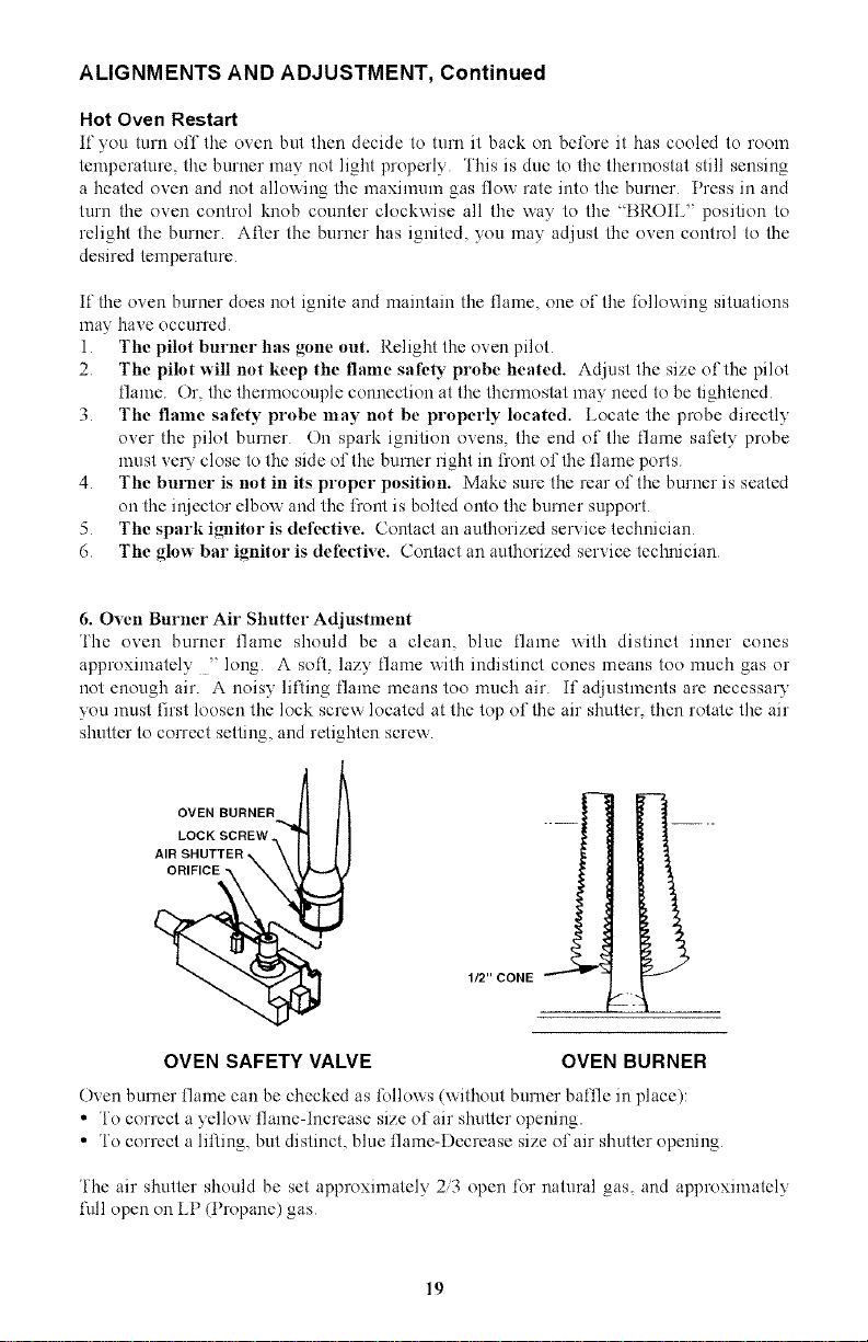
6. Oven Burner Air Shutter Adjustlnent
i'he oven burner flame should be a clean, blue flame with distinct inner cones
approximately " long A soil, lazy flame with indistinct cones means too much gas or
not enough air. A noisy lilting flame means too much air if adjustments are necessary
you must first loosen tile lock screw located at tile top of tile air shutter, then rotate the air
shutter to correct setting, and retighten screw
OVEN BURNER
LOCK SCREW
AIR SHUTTER
ORIFICE_
OVEN SAFETY VALVE OVEN BURNER
Oven burner flame can be checked as follows (xxithout burner baflle in place):
• fo correct a yellow flame-increase size of air shutter opening.
• fo correct a lifting, but distinct, blue flame-Decrease size of air shutter opening
fhe air shutter should be set approximately 2/3 open for natural gas, and approximately
l\fll open on LP (Propane) gas
19
ALIGNMENTS AND ADJUSTMENTS, Continued
Ovens _,_,rithPilotless Electric Ignition: Glow Bar Ignition System (-7 Models)
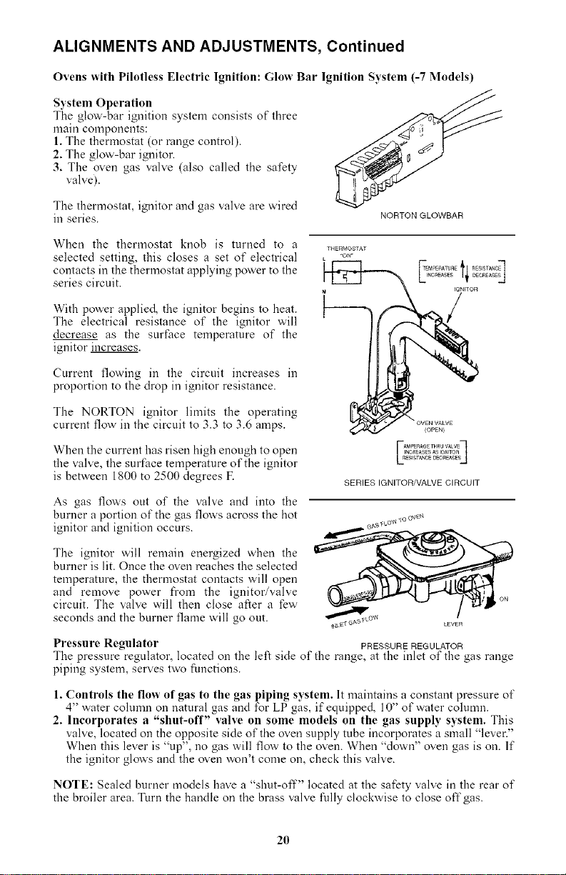
System Operation
The glow-bar ignition system consists of three
main components:
1. The thermostat (or range control).
2, The glow-bar ignitor.
3, The oven gas valve (also called the safety
valve).
The thermostat, ignitor and gas valve are wired
in series. NORTON GLOWBAR
When the thermostat knob is turned to a
selected setting, this closes a set of electrical
contacts in the thermostat applying pow'er to the
series circuit.
With power applied, the ignitor begins to heat.
The electrical resistance of the ignitor will
decrease as the surface temperature of the
ignitor increases.
Current flowing in the circuit increases in
proportion to the drop in ignitor resistance.
The NORTON ignitor limits the operating
current flow' in the circuit to 3.3 to 3.6 amps.
When the current has risen high enough to open
the valve, the surface temperature of the ignitor
is between 1800 to 2500 degrees F.
As gas flows out of the valve and into the
burner a portion of the gas flow's across the hot
ignitor and ignition occurs.
SERIES IGNITOR/VALVE CIRCUIT
The ignitor will remain energized when the
burner is lit. Once the oven reaches the selected
temperature, the thermostat contacts will open
and remove power from the ignitor/valve
circuit. The valve will then close after a few
seconds and the burner flame will go out.
Pressure Regulator PRESSURE REGULATOR
The pressure regulator, located on the left side of the range, at the inlet of the gas range
piping system, serves two functions.
1. Controls the flow of gas to the gas piping system. It maintains a constant pressure of
4" water column on natural gas and for LP gas, if equipped, 10" of water column.
2. Incorporates a "shut-off" valve on some models on the gas supply system. This
valve, located on the opposite side of the oven supply tube incorporates a small "lever."
When this lever is "up", no gas will flow to the oven. When "down" oven gas is on. If
the ignitor glow's and the oven won't come on, check this valve.
NOTE: Sealed burner models have a "shut-off" located at the safety valve in the rear of
the broiler area. Turn the handle on the brass valve fully clockwise to close off gas.
2O
OPERATION OF RANGE
Using Your Range
The range may have only part of the features described within this manual. If your range
has some features which are not covered in this manual, these features will be covered in
other enclosed literature.
Top Burner Operation
Note." When boiling food, the highest temperature that can be reached is the boiling point.
When the liquid starts to boil, decrease the size of the flame until you reach the minimum
flame that will hold the boil. This will save gas. It will also lessen the possibility of
burning food or boiling food over, and help to keep your kitchen cooler. Use stable utensils
with flat bottoms and always place the utensil on the burner grate before lighting the
burnet_ Unstable or rounded bottom utensils will not contact properly with the grate and
will affect the cooking efficiency. Select utensils large enough to avoid spillovers, but
remember, over-sized utensils (diameters exceeding 8 1/2") can cause the range finish to
discolor, craze or chip. Damage caused by oversized utensils, such as those sometimes
used in canning, are not covered by the warranty. The finish has been manufactured to a
commercially acceptable standard and its condition is dependent upon the care of the user.
Top Burner Valves
The top burner flame size should be adjusted so that is does not extend beyond the edge
of the cooking utensil. As a matter of safety, it's urged that you comply with these
instructions.
A high flame on a surface burner is both inefficient and unsafe. The flame should always
be adjusted so that it is no larger than the bottom of the pan. Fluctuations in flame size
could be caused by pressure variations, improperly positioned burners, damage or debris.
Preheating
Heat the oven for 10 to 12 minutes to reach temperature before placing food in the oven.
Arranging Oven Racks
The oven racks should be arranged before the oven is turned "ON." Place the racks so the
food is centered in the oven.
Opening Oven Door
Let hot air or steam escape before removing or replacing food.
Temperature Selection
It is important to select to proper temperature setting. Never set the dial to a higher degree
than needed w'ith the intention of lowering the setting at a later time. This will not speed
up the action. It can cause temperatures to vary so that cooking results may be
unsatisfactory, hnagine that the control has three sections: Warm, Bake, and Broil,
Warming
The broiler section of your range can function as a warming drawer to keep foods at
serving temperature (175°F to 225°F). Place food on the broiler pan in the low position
and set the oven control to the lowest setting. ("WM").
21
Baking
Follow the recipe instructions when baking. Use correct ingredients, measure them
carefully, and use the correct type and size of utensil suggested in the recipe. Remember
to preheat properly. Avoid opening of the oven door as much as possible when baking.
When baking cakes in glass baking dishes, lower the oven temperature 25°F to prevent
browning of the bottom and sides before the top becomes brown.
Also when using glass bakeware it would be better to increase the preheat time to have
exact stabilization of the oven's temperature. To do so allow 20 minutes time for
temperatures up to 350°F and 30 minutes for temperatures up to 425°E
Oven Racks
The oven racks should be arranged before the oven knob is turned to an "ON" position.
Place the racks so the food is centered in the oven, not the rack.
When more than one utensil is used, be sure to stagger them allowing space between each
one. Do not allow the utensil to touch any part of the oven, especially the glass window.
It is best to use two racks and place food so one utensil is not directly over another.
Rack Removal
Pull the oven rack forward and lift up on the front of the rack so it will clear the rack
keeper.
To replace the oven rack, guide the angled rear portion of the rack under the rack keeper
and slide the rack to the rear.
Never cover the oven racks with aluminum foil. Such practices will trap heat and cause
intense heat in spots which usually give poor results. It can damage the porcelain finish as
well as glass windows in oven doors (if equipped). 11-97
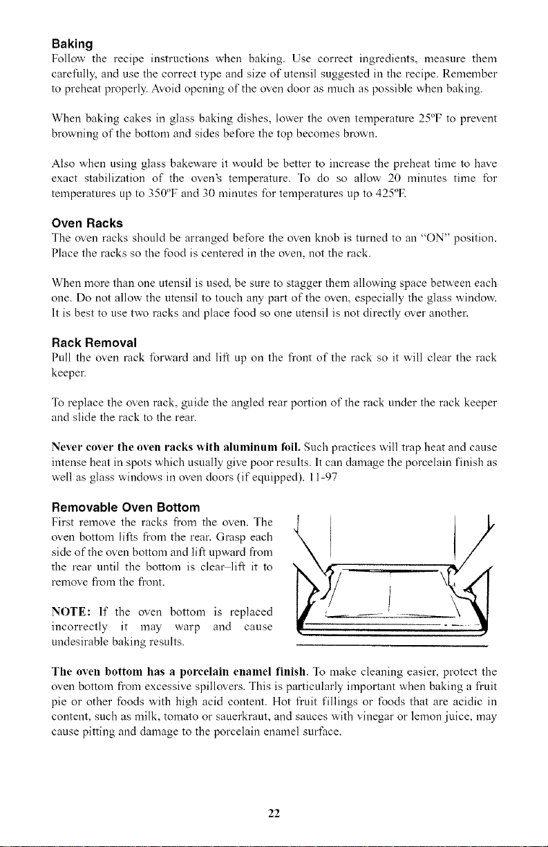
Removable Oven Bottom
First remove the racks from the oven. The
oven bottom lifts from the rear. Grasp each
side of the oven bottom and lift upward from
the rear until the bottom is cleat" lift it to
remove fl'om the fl'ont.
NOTE: If the oven bottom is replaced
incorrectly it may warp and cause
undesirable baking results.
The oven bottom has aporcelain enamel finish. To make cleaning easier, protect the
oven bottom from excessive spillovers. This is particularly important when baking a fruit
pie or other foods with high acid content. Hot fi'uit fillings or foods that are acidic in
content, such as milk, tomato or sauerkraut, and sauces with vinegar or lemon juice, may
cause pitting and damage to the porcelain enamel surface.
22
To protect the oven bottom surfuce, place a piece of aluminum foil slightly larger than the
baking dish on the rack below to catch any boilovers. It should not completely cover the
rack as this would cause uneven heat in the oven. Aluminum foil should not be placed on
the oven bottom.
If a spillover does occur on the oven bottom, allow the oven to cool first. You can clean
the bottom with soap and water, a mild abrasive cleanser, soap-filler abrasive pads or an
oven cleaner following package directions.
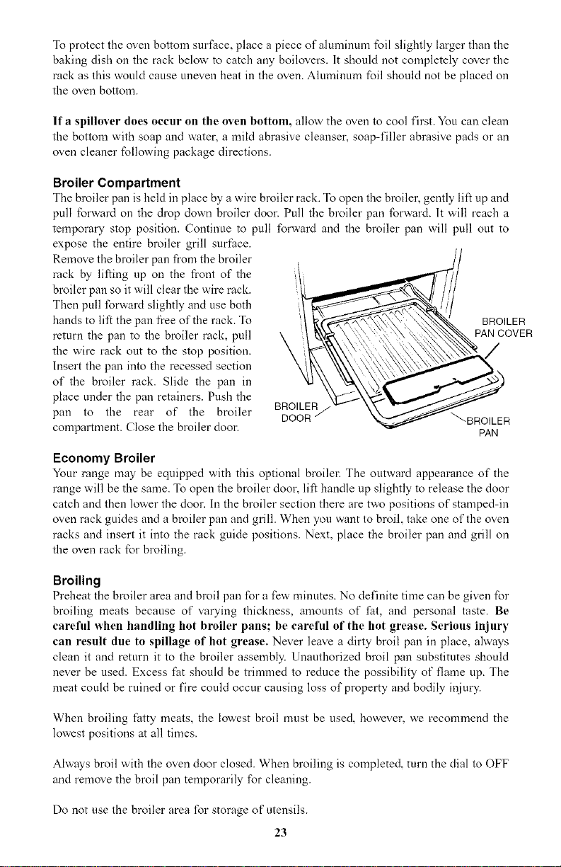
Broiler Compartment
The broiler pan is held in place by a wire broiler rack. To open the broiler, gently lift up and
pull forward on the drop down broiler door. Pull the broiler pan forward. It will reach a
temporary stop position. Continue to pull forward and the broiler pan will pull out to
expose the entire broiler grill surface.
Remove the broiler pan from the broiler
rack by lifting up on the front of the
broiler pan so it will clear the wire rack.
Then pull forward slightly and use both
hands to lift the pan fi'ee of the rack. To
return the pan to the broiler rack, pull
the wire rack out to the stop position.
Insert the pan into the recessed section
of the broiler rack. Slide the pan in
place under the pan retainers. Push the
pan to the rear of the broiler
compartment. Close the broiler dool_
BROILER/
DOOR
BRO,LER
_BROILER
PAN
Economy Broiler
Your range may be equipped with this optional broile_ The outward appearance of the
range will be the same. To open the broiler door, lift handle up slightly to release the door
catch and then lower the door. In the broiler section there are two positions of stamped-in
oven rack guides and a broiler pan and grill. When you want to broil, take one of the oven
racks and insert it into the rack guide positions. Next, place the broiler pan and grill on
the oven rack for broiling.
Broiling
Preheat the broiler area and broil pan for a few" minutes. No definite time can be given for
broiling meats because of varying thickness, amounts of fat, and personal taste. Be
careful when handling hot broiler pans; be careful of the hot grease. Serious injury
can result due to spillage of hot grease. Never leave a dirty broil pan in place, always
clean it and return it to the broiler assembly. Unauthorized broil pan substitutes should
never be used. Excess fat should be trimmed to reduce the possibility of flame up. The
meat could be ruined or fire could occur causing loss of property and bodily injury.
When broiling fatty meats, the lowest broil must be used, however, we recommend the
lowest positions at all times.
Always broil with the oven door closed. When broiling is completed, turn the dial to OFF
and remove the broil pan temporarily for cleaning.
Do not use the broiler area for storage of utensils.
23
OPTIONAL EQUIPMENT
Continuous Cleaning Feature
If your oven has the continuous cleaning feature, it will have a dull gray finish with white
speckles that has been blended with a special catalytic material. (lf the oven has a glossy
finish, it is standard porcelain enamel without the continuous cleaning feature.)
Bt_[bre [/i_ing Ii)ur Oven-Read These Instructions Care.[ttlly.
Using The Continuous Cleaning Oven
The catalytic finish will keep your oven presentably clean with some effort on your part.
Any time the oven is in use, the catalytic action will be working to eliminate normal
cooking spatters. Simply cook as you usually do. Average oven spatters should fade away.
If a great deal of spattering occurs during cooking, a small amount may remain on the
suriace of the oven interior at the end of the cooking time. This is particularly true during
a short cooking cycle. The longer the cooking cycle, the better the catalytic action.
Cleaning time depends on the type, size and amount of soil, and oven temperature. The
cleaning time will vary from a few minutes to several hours. The oven will never get
completely clean it will appear "presentably clean," even though some stains or spatters
may be present.
Heavy Spillovers-Unusual Stains
The continuous cleaning oven feature will make cleanups easy. However, some spills or
food types are harder for the oven to clean without a little assistance. For heavy spillovers,
such as fi'om an overfilled fruit pie or casserole, put a cookie sheet or aluminum foil on
the oven bottom. Be sure the foil does not cover the air openings, so do not extend foil
beyond oven bottom.
lfyou shouhl get a heavy spillover on the oven bottom:
1. Brush off heavy soil with a nylon brush or plastic pad. DO NOT USE paper toweling,
cloths or sponge. Oven walls are porous and particles of these materials will rub off on
walls. Rinse area well with clean water only. Do not allow insulation under oven bottom
to become wet.
2. If spillovers harden before they can be wiped away, they may become either a brittle
crust or a varnish-type coating. The brittle crusts will loosen and flake off in time. This
process can be speeded up by GENTLY tapping crust with a wooden or plastic utensil
and then brushing crust away.
3. Any remaining soil will gradually reduce with continued oven use at normal baking
temperatures.
DO NOT USE ANY TYPE OF OVEN CLEANER, POWERED CLEANSERS, SOAR
DETERGENT OR PASTE ON ANY CONTINUOUS CLEANING SURFACE. ALSO,
DO NOT USE ANY ABRASIVE MATERIALS, STEEL WOOL, SHARP
INSTRUMENTS OR SCRAPERS. THEY WILL DAMAGE THE FINISH.
Note: Over a period of time, wear marks may appear on the embossed rack supports. This
is normal and results from sliding the oven racks in and out of the oven. Wear marks will
not interfere with the overall cleaning action of the oven.
24
OPTIONAL EQUIPMENT, Continued
Backguard and Control Panel Features
Electrical Grounding Instructions: This appliance, when equipped with
I"IAWARNINGelectrical equipment, has a three-prong grounding plug for your protection
and should be plugged directly into a properly grounded receptable. Do not
cut or remove ground prong.
The backguard equipment is optional, depending on model selection. The range you have
purchased may or may not be equipped with the features that are illustrated in this section.
The clocks have been placed into separate groups.
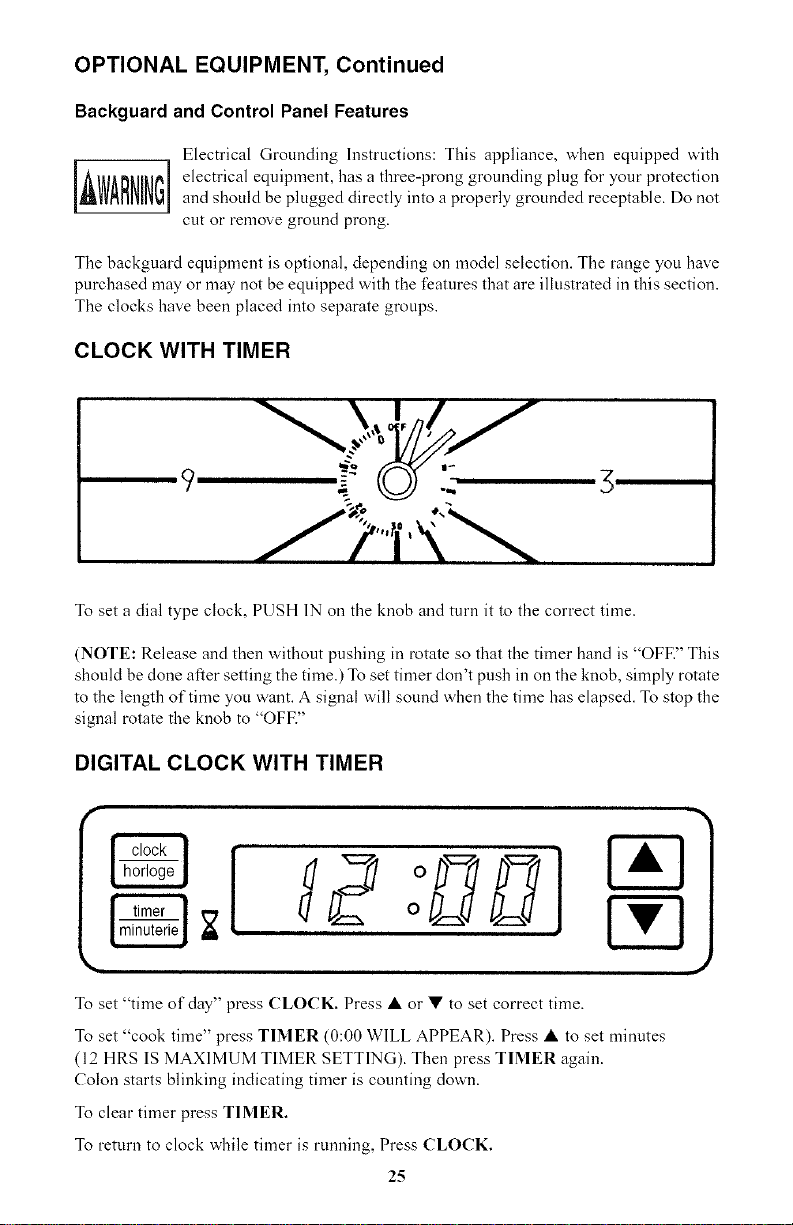
CLOCK WITH TIMER
9
To set a dial type clock, PUSH 1N on the knob and turn it to the correct time.
(NOTE: Release and then without pushing in rotate so that the timer hand is "OFE" This
should be done after setting the time.) To set timer don't push in on the knob, simply rotate
to the length of time you want. A signal will sound when the time has elapsed. To stop the
signal rotate the knob to "OFE"
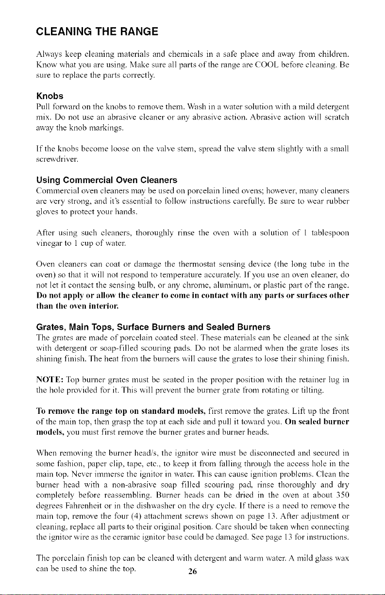
DIGITAL CLOCK WITH TIMER
To set "time of day" press CLOCK. Press •or • to set correct time.
To set "cook time" press TIMER (0:00 WILL APPEAR). Press • to set minutes
(12 HRS IS MAXIMUM TIMER SETTING). Then press TIMER again.
Colon starts blinking indicating timer is counting down.
To clear timer press TIMER.
To return to clock while timer is running, Press CLOCK.
25
CLEANING THE RANGE
Always keep cleaning materials and chemicals in a safe place and away from children.
Know what you are using. Make sure all parts of the range are COOL before cleaning. Be
sure to replace the parts correctly.
Knobs
Pull forward on the knobs to remove them. Wash in a water solution with a mild detergent
mix. Do not use an abrasive cleaner or any abrasive action. Abrasive action will scratch
away the knob markings.
lfthe knobs become loose on the valve stem, spread the valve stem slightly with a small
screwdriver.
Using Commercial Oven Cleaners
Commercial oven cleaners may be used on porcelain lined ovens; however, many cleaners
are very strong, and it's essential to follow' instructions carefully. Be sure to wear rubber
gloves to protect your hands.
After using such cleaners, thoroughly rinse the oven with a solution of 1 tablespoon
vinegar to l cup of water.
Oven cleaners can coat or damage the thermostat sensing device (the long tube in the
oven) so that it will not respond to temperature accurately, lfyou use an oven cleaner, do
not let it contact the sensing bulb, or any chrome, almninuln, or plastic part of the range.
Do not apply or allow the cleaner to come in contact with any parts or surfaces other
than the oven interior.
Grates, Main Tops, Surface Burners and Sealed Burners
The grates are made of porcelain coated steel. These materials can be cleaned at the sink
with detergent or soap-filled scouring pads. Do not be alarmed when the grate loses its
shining finish. The heat from the burners will cause the grates to lose their shining finish.
NOTE: Top burner grates must be seated in the proper position with the retainer lug in
the hole provided for it. This will prevent the burner grate fl'om rotating or tilting.
To remove the range top on standard models, first remove the grates. Lift up the front
of the main top, then grasp the top at each side and pull it toward you. On sealed burner
models, you must first remove the burner grates and burner heads.
When removing the burner head/s, the ignitor wire must be disconnected and secured in
some fashion, paper clip, tape, etc., to keep it from falling through the access hole in the
main top. Never immerse the ignitor in water: This can cause ignition problems. Clean the
burner head with a non-abrasive soap filled scouring pad, rinse thoroughly and &y
completely before reassembling. Burner heads can be dried in the oven at about 350
degrees Fahrenheit or in the dishwasher on the dry cycle. If there is a need to remove the
main top, remove the four (4) attachment screws shown on page 13. After adjustment or
cleaning, replace all parts to their original position. Care should be taken when connecting
the ignitor wire as the ceramic ignitor base could be damaged. See page 13 for instructions.
The porcelain finish top can be cleaned with detergent and warm water. A mild glass wax
can be used to shine the top. 26
CLEANING THE RANGE, Continued
Range tops finished in brushed chrome should be wiped clean of spaters or soiling after
each use. Clean with a paper towel or a damp cloth. For heavy spatters, use a mild
detergent and water. Wipe dry with a soft cloth.
A light coat of oil or thin cooking oil should be applied periodically to the chrome top
surface and underside. This will help prevent moisture from penetrating the chrome surfhce.
Products of combustion from the top pilots as well as certain atmospheric conditions can
create an oxidation reaction on the underside of the top. This will appear as rust or in the
form of a reddish brown deposit. This will NOT AFFECT THE LIFE OF THE TOP in
comparison to the general life expectancy of the range itself.
The grate and main top should be removed to gain access to the surface burners. Remove
the burner and let it soak in hot sudsy water. Most stains will then wipe ofL if not, scrub
with a strong but non-abrasive cleaning pad. Rinse the burner thoroughly.
It is very important that the burner be dry before replacing it in the range. A wet burner
will not allow the gas to ignite properly. This could result in a build-up of gas which could
result in an explosion or fire.
Aluminum Foil in Oven and Broiler
Aluminum foil when used improperly is a cause of many range fires. Make certain that
vents or air openings aren't covered by the foil. lfthe vents located along the sides of the
oven bottom are blocked, poor cooking will result.
Never cover a rack completely. A piece of foil slightly larger than the utensil can be placed
on the rack beneath the utensil.
Remove and discard aluminum foil after each use. This will help prevent greases and
spilled food from accumulating and becoming a fire hazard.
Cleaners and Cleaning Materials
Do not use harsh cleaners or degreasers on or around functional parts (valves, controls,
etc., or aluminum tubing). This will damage or drastically reduce the life of the part.
Use only a mild solution of soap and water on backguards, aluminum control panels
and painted surfaces. Never use harsh abrasives or cleaning powders that may scratch or
mar the surface. Make sure the cleaners and cleaning materials are suitable for use on the
area to be cleaned. Always keep cleaning materials in a safe place. Never use a sharp metal
scraper to clean glass, porcelain, or painted suri, ices.
Repair Parts
When repair parts are needed, contact the dealer from whom the range was purchased. In
case your range was purchased from a source other than an appliance dealer you may
prefer to contact the manufacturer at the address shown in this manual.
Moisture
During the initial heat-up of your range, the heat mixing with the cooler air in the oven
cavity may produce fogging of the door glass or a collection of water on the door. To
27
CLEANING THE RANGE, Continued
prevent this, open the oven door for the first few seconds of initial oven heat-up. This will
allow the moist air within the oven to escape without the forming of visible moisture on
the range. The amount of moisture will depend upon the humidity of the air and water
content of the food being cooked. Fogging and even dripping water will usually occur in
geographic locations of high humidity.
LIFT-OFF DOORS
To lock
apply
force
Locking mechanism lever To unlock apply force
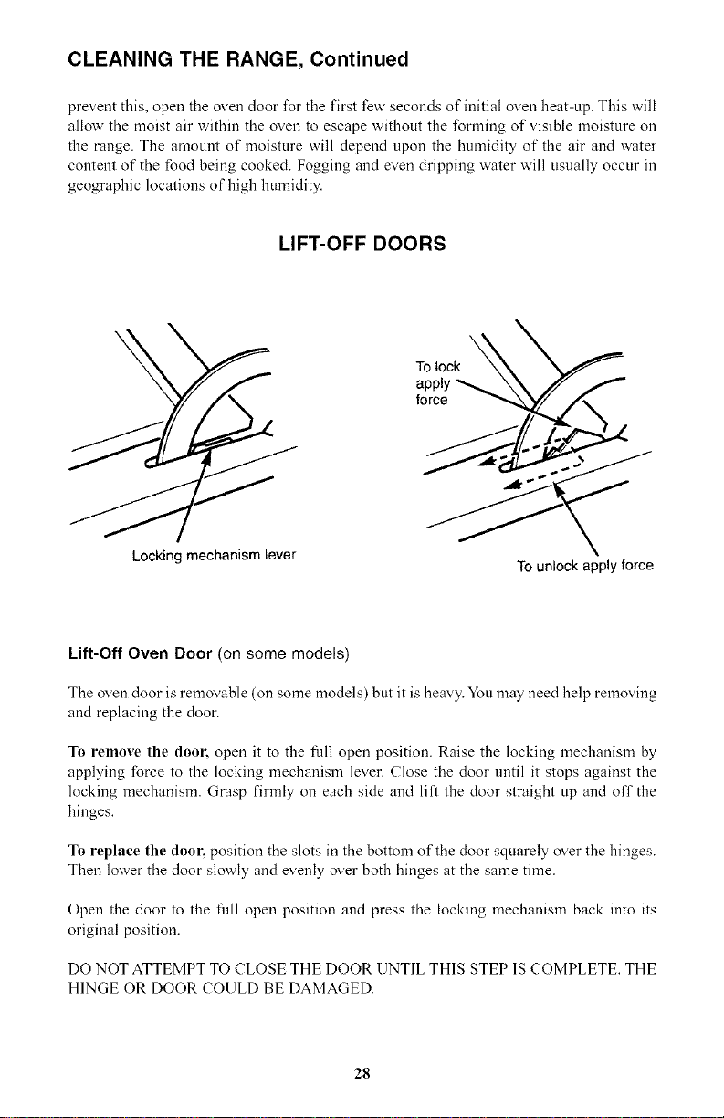
Lift-Off Oven Door (on some models)
The oven door is removable (on some models) but it is heavy. You may need help removing
and replacing the door.
To remove the door, open it to the full open position. Raise the locking mechanism by
applying force to the locking mechanism lever. Close the door until it stops against the
locking mechanism. Grasp firmly on each side and lift the door straight up and off the
hinges.
To replace the door, position the slots in the bottom of the door squarely over the hinges.
Then lower the door slowly and evenly over both hinges at the same time.
Open the door to the full open position and press the locking mechanism back into its
original position.
DO NOT ATTEMPT TO CLOSE THE DOOR UNTIL THIS STEP 1S COMPLETE. THE
HINGE OR DOOR COULD BE DAMAGED.
28
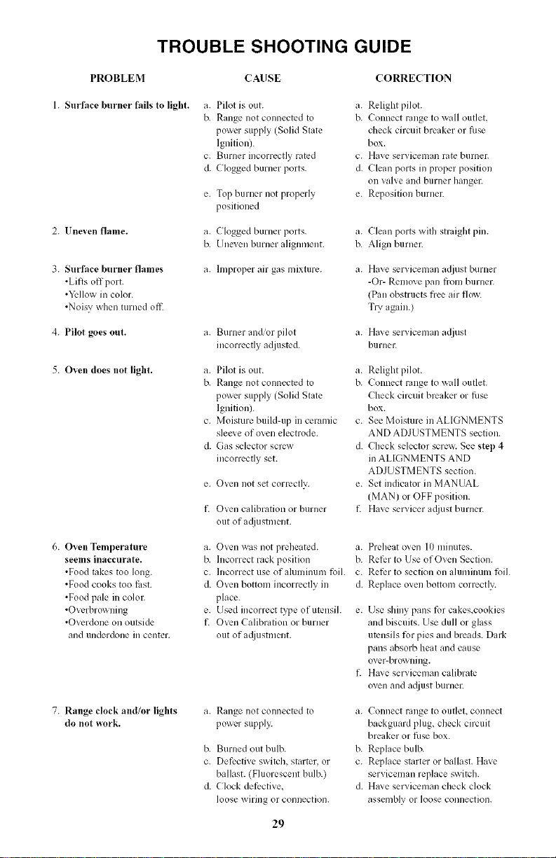
TROUBLE SHOOTING GUIDE
PROBLEM CAUSE CORRECTION
1. Surface burner fails to light.
2. Uneven flame.
3. Surface burner flames
•Lifts off port.
•Yellow in color.
•Noisy when turned off'.
4. Pilot goes out.
5. Oven does not light.
a. Pilot is out. a. Relight pilot.
b. Range not connected to b. Connect range to wall outlet,
power supply (Solid State check circuit breaker or fuse
Ignition). box.
c. Burner incorrectly rated c. Have serviceman rate burner.
d. Clogged burner ports, d. Clean ports m proper position
on valve and burner hanger.
e. Top burner not properly e. Reposition burner.
positioned
a. Clogged burner ports, a. Clean ports with straight pin.
b. Une;en burner alignment, b. Align burner.
a. hnproper air gas mixture, a.
a. Burner and/or pilot
incorrectly a([iustcd.
a. Pilot is out.
b. Range not connected to
power supply (Solid State
Ignition).
c. Moisture build-up in ceramic
slee; e of oven electrode.
d. Gas selector screw
incorrectly set.
e. Oven not set correctly.
t2 Oven calibration or burner
out of a@lstment.
Have serviceman a(liust burnur
-Or- Remove pan from burner.
(Pan obstructs flee air flow.
Try again.)
a. Ha;e serviceman a;liust
burnec
a. Relight pilot.
b. Connect range to wall outlet.
Check circuit breaker or tilse
box.
c. See Moisture inALIGNMENTS
AND ADJUSTMENTS section.
d. Check selector screw. See step 4
in ALIGNMENTS AND
ADJUSTMENTS section.
e. Set indicator in MANUAL
(MAN) or OFF position.
t_ Have servicer a@lst burner.
6. Oven Temperature
seems inaccurate.
•Food takes too long.
•Food cooks too titst.
•Food pale m color.
.Overbrowning
•Overdone on outside
and underdone m center.
a. Oven was not preheated, a.
b. Incorrect rack position b.
c. Incorrect use of aluminum foil. c.
d. Oven bottom incorrectly in d.
place.
e. Used incorrect type of utensil, e.
t_ Oxen Calibration or burner
out of a_[justnlent.
Preheatoven 10minutes.
Refer to Use of Oven Section.
Refer to section on aluminum foil.
Replace oven bottom correctly.
Use shiny pans for cakes,cookies
and biscuits. Use dull or glass
utensils for pies and breads. Dark
pans absorb heat and cause
over-browning.
Ha; e serviceman calibrate
oven and a_!iustburner.
7. Range clock and/or lights
do not work. a. Range not connected to
power supply.
b. Burned out bulb.
c. Detk,ctive switch, st:trtcr, or
ballast. (Fluorescent bulb.)
d. (-loci< detk, ctive,
loose wiring or connection.
a. Connect range to outlet, connect
backguard plug, checl< circuit
breaker or fuse box.
b. Replace bulb.
c. Replace starter or ballast. Have
serviceman replace switch.
d. Ha;e serviceman check clock
assembly or loose connection.
29
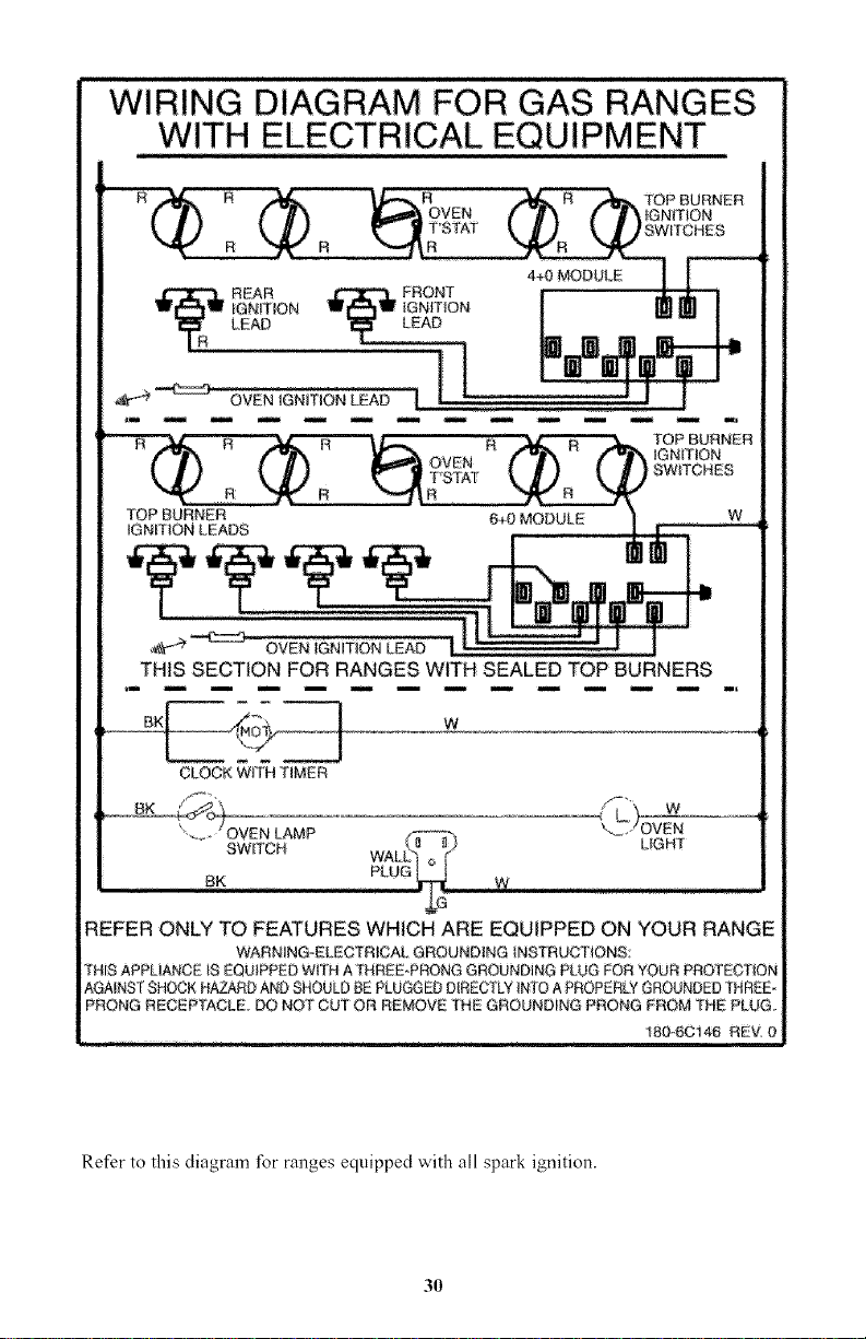
WIRING DIAGRAM FOR GAS RANGES
WITH ELECTRICAL EQUIPMENT
R
R
TOP BURNER
OVEN iGNITION
T'BTAT SWITCHES
_ _ OVEN IGNmON LEAD I I [
R
OVEN
T'S'[AT
R
"fOP BURNER
IGNITION LEADS
_GNmON
SWITCHES
6_ MODULE W
THIS SECTION FOR RANGES WITH SEALED TOP BURNERS
BK[ W
tCLOCK WiTH TIMER
'.._. " OVETN[ LAMP
SW.. CH WAL[_; LIGHT
BK PLUG _ W
REFER ONLY TO FEATURES WHICH ARE EQUIPPED ON YOUR RANGE
WARNING-ELECTRICAL GROUNDING INSTRUCTIONS:
THiS APPLIANCE iS EQUIPPED WI"_H ATHREE PRONG GROUNDING PLUG FOR YOUR PROTEC'_ION
AGAINST SHOCK HAZARD AND SHOULD BE PLUGGED DIRECTLY INTO A PROPERLY GROUNDED THREE
PRONG RECEPTACLE. DO NOT CUT OR REMOVE THE GROUNDING PRONG FROM "[HE PLUG
t80-6C1_ REV O
Refer to this diagram for ranges equipped with all spark ignition.
3O
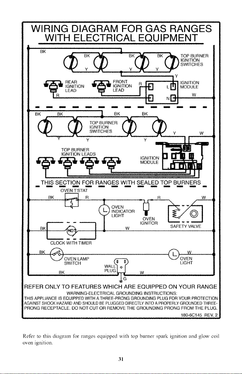
WIRING DIAGRAM FOR GAS RANGES
WITH ELECTRICAL EQUIPMENT
8K TOP BURNER
IGNITION
swrrcHEB
REAR FRONT IGNmON
IGNmON IGNiTiON MODULE
LEAD LEAD w
n
Bw
THIS SECTION FOR RANGES WITH SEALED TOP BURNERS
OVEN T'STAT
BK }_ R .
CLOCK WITH TIMER
OVEN
INDICf_"OR
LIGHT OVEN
iGNiTOR SAFETY VALVE
REFER ONLY TO FEATURES WHICH ARE EQUIPPED ON YOUR RANGE
WARN[NG_ELECTRICAL GROUNDING INSTRUCTIONS:
THiS APPUANCE IS EQUIPPED Wl[H A THREE PRONG GROUNDING PLUG FOR "{OUR PRO'_ECT_ON
AGNNST SHOCK HAZARD AND SHOULD BE PLUGGED DIRECTLY iNTO A PROPERLY GROUNDED THRED
PRONG RECEPTACLE DO NOT CUT OR REMOVE THE GROUNDmNG PRONG PROM "[HE PLUG,
, ,, 180,_6C145 REV, 2
Refer to this diagram for ranges equipped with top burner spark ignition and glow coil
oven ignition.
31
What is covered and for how long?
This warranty covers all ddeds in
workmanship or materials for a period of:
12 months labor
12 months ports
The warranty commences on tJ_edate the item was put
chased and the original purchase receipt must be pre-
sented to the authorized service center before warranly
repairs are rendered
EXCEPTIONS: Commercial or Rental Use
warran W
90 days Jabot (carry-in only)
90 days parts
No other warranty applies
What is covered.
1The mechanical and electrical parts, which serve as a
functional, purpose of this appliance for a period of
12 mantles This includes all parts except finish, and
trh_
What will be done?
1 We will repair or replace, at our discretion any
mechanical or electrical part which proves to be
defective in normal usage during the warranty period
so specified
2 There wiJJ be no charge to the purchaser for parts
and labor on any covered items during the initial 12
monfl_ period
3 Contact your nearest aufl_orized service center For
tl_e name of tile nearest service center please call
1 877 337 3639
THiS WARRANTY COVERS APPLIANCES WiTHiN
THE CONTINENTAL UNITED STATES, PUERTO
RICO AND CANADA. IT DOES NOT COVER
THE FOLLOWING:
Damages from improper installation
Damages in shipping
Defects other than manufacturing
Damage from misuse, abuse, accident, alteration, lack
of proper care and maintenance or incorrect current
or
voltage
Damage from other titan household use
Damage from service by other than an aufl_orfzed
dealer or service center
Decorative trims or replaceable
light bulbs
]ransportation and shipping
THIS LIMITED WARRANTY JS GIVEN JN LIEU OF ALL
OTHER WARRANTIES, EXPRESSED OR, INCLUDING THE
WARRANTIES OF MERCHANTABILITY AND FITNESS FOR
A PARTICULAR PURPOSE
The remedy provided in tilis warranly is exclusive and is
granted in lieu of all other remedies
This warranly does not cover incidental or consequential
damages, so tl_e above limitations may not apply to
you Some States do not allow limitations on how long
an implied warranty Justs, so the above limitations may
not apply to you
This warranly gives you specific legal rights, and you
may have otl_er rights, which vary, from state to state
Haier Amedca
New York, NY 10018
PART NO. 180-6C152 (6-06)