Operating and installation
instructions
Induction hobs
To avoid the risk of accidents or damage to the appliance it is essen-
tial to read these instructions before it is installed and used for the
first time.
en-GB M.-Nr. 12 294 640


Contents
3
Warning and Safety instructions...................................................................... 6
Caring for the environment .............................................................................. 19
Guide to the appliance...................................................................................... 20
Hob...................................................................................................................... 20
Controls and display ........................................................................................... 22
Cooking zones..................................................................................................... 24
Accessories supplied .......................................................................................... 25
Before using for the first time .......................................................................... 26
Cleaning the hob for the first time....................................................................... 26
Switching on the hob for the first time ................................................................ 26
Using the vapour extraction for the first time...................................................... 26
Miele@home........................................................................................................ 27
How it works ...................................................................................................... 30
Cooking zones..................................................................................................... 30
Noises............................................................................................................. 30
Power management ....................................................................................... 31
Vapour extraction ................................................................................................ 32
Pans .................................................................................................................... 33
Tips on saving energy ...................................................................................... 35
Setting ranges.................................................................................................... 36
Operation............................................................................................................ 37
Using the appliance............................................................................................. 37
Switching on the hob .......................................................................................... 38
Setting the power level........................................................................................ 38
Changing the power level.................................................................................... 38
Switching off a cooking zone/the hob................................................................. 38
Residual heat indicator........................................................................................ 39
Setting the power level – extended setting range ............................................... 39
Flex cooking area ................................................................................................ 40
Auto heat-up ....................................................................................................... 41
Booster function.................................................................................................. 42
Keeping warm ..................................................................................................... 43
Vapour extraction ................................................................................................ 44
Timer................................................................................................................... 46
Minute minder ..................................................................................................... 46
Auto switch off .................................................................................................... 47

Contents
4
Using both timer functions at the same time ...................................................... 48
Additional functions .......................................................................................... 49
Stop&Go............................................................................................................ 49
Recall................................................................................................................... 49
Wipe protection ................................................................................................... 50
Demo mode......................................................................................................... 50
Displaying hob data............................................................................................. 50
Safety features................................................................................................... 51
System lock/safety lock ...................................................................................... 51
Safety switch-off ................................................................................................. 52
Overheating protection........................................................................................ 53
Programming ..................................................................................................... 54
Note for test institutes ...................................................................................... 58
Cleaning and care ............................................................................................. 59
Cover grille/grease filter/charcoal filter................................................................ 61
Removing the cover grille............................................................................... 61
Cleaning the grease filter................................................................................ 62
Replacing the charcoal filter (only KMDA 7473 FR-U, KMDA 7473 FL-U) ..... 63
Cleaning the vapour extraction drip tray ............................................................. 63
Cleaning the inside of the fan unit....................................................................... 64
Resetting the grease filter operating hours counter ........................................... 64
Resetting the charcoal filter operating hours counter (only
KMDA 7473 FR-U, KMDA 7473 FL-U)................................................................. 64
Problem solving guide ...................................................................................... 65
Messages in the display...................................................................................... 65
Unexpected behaviour ........................................................................................ 67
Unsatisfactory results.......................................................................................... 68
General problems or technical faults................................................................... 68
Optional accessories ........................................................................................ 70
Installation.......................................................................................................... 71
Safety instructions for installation ....................................................................... 71
Safety distances.................................................................................................. 73
Operating options................................................................................................ 76
Installation examples........................................................................................... 77
Installation notes – surface-mounted.................................................................. 79

Contents
5
Installation dimensions–Surface-mounted........................................................ 82
KMDA 7473 FR-A, KMDA 7473 FR-U ............................................................ 82
KMDA 7473 FL-A, KMDA 7473 FL-U.............................................................. 83
Extraction and guided recirculation mode ..................................................... 84
Plug&Play mode ............................................................................................. 86
Connection to window contact, if required ......................................................... 88
Surface-mounted installation .............................................................................. 90
Installation notes – flush-fit ................................................................................. 91
Installation dimensions–Flush-fit....................................................................... 94
KMDA 7473 FL-A, KMDA 7473 FL-U.............................................................. 94
Extraction and guided recirculation mode ..................................................... 95
Plug&Play mode ............................................................................................. 96
Connection to window contact, if required ......................................................... 97
Flush-fit installation ............................................................................................. 99
Rear wall cut-out – without drilling template....................................................... 100
Ducting ................................................................................................................ 102
Electrical connection ........................................................................................... 103
After sales service............................................................................................. 106
Contact in the event of a fault ............................................................................. 106
Data plate ............................................................................................................ 106
Warranty .............................................................................................................. 106
Product data sheets ......................................................................................... 107
UK Conformity declaration............................................................................... 109
Warning and Safety instructions
6
This hob complies with all relevant local and national safety re-
quirements. Inappropriate use can, however, lead to personal in-
jury and material damage.
Read the operating and installation instructions carefully before
using the hob. They contain important information on safety, in-
stallation, use and maintenance. This prevents both personal injury
and damage to the hob.
In accordance with standard IEC60335-1, Miele expressly and
strongly advises that you read and follow the instructions in the
chapter on installing the hob as well as the safety instructions and
warnings.
Miele cannot be held liable for injury or damage caused by non-
compliance with these instructions.
Keep these instructions in a safe place and pass them on to any
future owner.

Warning and Safety instructions
7
Correct application
This hob is intended for domestic use and use in other similar en-
vironments.
This hob is not intended for outdoor use.
It is intended for domestic use only to cook food and keep it
warm. Any other use is not supported by the manufacturer and could
be dangerous.
This hob is not intended for use by people with reduced physical,
sensory or mental capabilities or lack of experience and knowledge,
unless they have been given supervision and instruction concerning
its use by a person responsible for their safety. They may only use
the hob unsupervised if they have been shown how to use it in a
safe way. They must be able to recognise and understand the
dangers of misuse.

Warning and Safety instructions
8
Safety with children
Children under 8 years of age must be kept away from the hob
unless they are constantly supervised.
Children over 8years of age may use the hob without supervision
if its operation has been clearly explained to them and they are able
to use it safely. Children must be able to understand and recognise
the possible dangers caused by incorrect operation.
Children must not be allowed to clean the hob unsupervised.
Please supervise children in the vicinity of the hob and do not let
them play with it.
The hob gets hot when in use and remains hot for a while after be-
ing switched off. Keep children well away from the hob until it has
cooled down and there is no danger of burning.
Danger of burning. Do not store anything which might arouse a
child’s interest in storage areas above or behind the hob. Otherwise
they could be tempted to climb onto the hob.
Risk of burning and scalding. Place pots and pans on the cooking
zone in such a way that children cannot pull them down and burn
themselves.
Danger of suffocation! Whilst playing, children may become en-
tangled in packaging material (such as plastic wrapping) or pull it
over their head with the risk of suffocation. Keep packaging material
away from children.
Activate the system lock to ensure that children cannot switch on
the hob inadvertently. Use the safety lock when the hob is in use to
prevent children from altering the settings selected.

Warning and Safety instructions
9
Technical safety
Unauthorised installation, maintenance and repairs can cause
considerable danger for the user. Installation, maintenance and re-
pairs must only be carried out by a Miele authorised technician.
Damage to the hob can compromise your safety. Check the hob
for visible signs of damage. Do not use the hob if it is damaged.
Temporary or permanent operation on an autonomous power sup-
ply system or a power supply system that is not synchronised with
the mains power supply (e.g. island networks, back-up systems) is
possible. A prerequisite for operation is that the power supply sys-
tem complies with the specifications of EN50160 or an equivalent
standard.
The function and operation of the protective measures provided in
the domestic electrical installation and in this Miele product must
also be maintained in isolated operation or in operation that is not
synchronised with the mains power supply, or these measures must
be replaced by equivalent measures in the installation. As described,
for example, in the current version of BS OHSAS 18001–2 ISO
45001.
The electrical safety of this hob can only be guaranteed when cor-
rectly earthed. It is essential that this standard safety requirement is
met. If in any doubt please have the electrical installation tested by a
qualified electrician.
To avoid the risk of damage to the hob, make sure that the con-
nection data on the data plate (voltage and frequency) match the
mains electricity supply before connecting it to the mains.
Consult a qualified electrician if in doubt.
Do not connect the hob to the mains electrical supply by a multi-
socket adapter or extension lead. These are a fire hazard and do not
guarantee the required safety of the appliance.
For safety reasons, this hob may only be used after it has been
built in.

Warning and Safety instructions
10
This hob must not be used in a non-stationary location (e.g. on a
ship).
Never open the casing of the hob.
Touching or tampering with electrical connections or components
and mechanical parts is highly dangerous to the user and can cause
operational faults.
While the hob is under warranty, repairs should only be under-
taken by a Miele authorised service technician. Otherwise the war-
ranty is invalidated.
Miele can only guarantee the safety of the appliance when genu-
ine original Miele replacement parts are used. Faulty components
must only be replaced by Miele spare parts.
The hob is not intended for use with an external timer switch or a
remote control system.
The hob must be connected to the electricity supply by a qualified
electrician (see “Installation – Electrical connection”).
If the mains connection cable is damaged, it must be replaced
with a special mains connection cable by a qualified electrician (see
“Electrical connection” in the “Installation” chapter).
The hob must be disconnected from the mains electricity supply
during installation, maintenance and repair work. Ensure that power
is not supplied to the appliance until after it has been installed or un-
til any maintenance or repair work has been carried out.
Danger of electric shock. Do not use the hob if it is faulty, or if the
ceramic surface is cracked, chipped or damaged in any way. Switch
it off immediately. Disconnect the hob from the mains electricity sup-
ply. Contact Miele Service.

Warning and Safety instructions
11
If the hob is installed behind a cabinet door, do not close the door
while the hob is in use. Heat and moisture can build up behind the
closed door. This can result in damage to the hob, the housing unit
and the floor. Do not close the door until the residual heat indicators
go out.
In areas which may be subject to infestation by cockroaches or
other vermin, pay particular attention to keeping the appliance and
its surroundings clean at all times. Any damage caused by cock-
roaches or other vermin will not be covered by the warranty.
Warning and Safety instructions
12
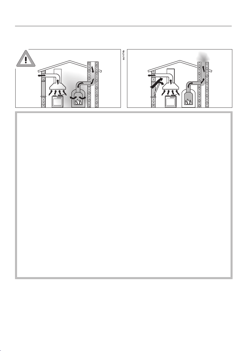
Using at the same time as other heating appliances that depend on the air
from the room
Danger of toxic fumes!
Great care should be taken when using the cooker hood in the
same room or the same area of the house as another heating ap-
pliance that depends on the air from the room.
Such heating appliances draw in air from the room and duct ex-
haust gases out through a chimney or extraction ducting. They in-
clude gas, oil, wood and coal-fired boilers and heaters, continuous
flow or other water heaters, gas hobs and ovens.
The cooker hood draws in air from the kitchen and from neigh-
bouring rooms. This applies to the following modes of operation:
- extraction mode,
- recirculation mode with a recirculation box installed outside the
room.
If there is insufficient air, an underpressure will occur. The heating
appliance may be starved of oxygen. This impairs combustion.
Harmful gases could be drawn from the chimney or extraction
ducting back into the room, with potentially fatal consequences.
Risk of death!

Warning and Safety instructions
13
In order to ensure safe operation and to prevent gases given off by
the heating appliance from being drawn back into the room, when
the cooker hood and the heater are both operated simultaneously,
an underpressure in the room of 0.04mbar (4Pa) is the maximum
permissible.
Sufficient ventilation can be maintained by air inlets which cannot
be blocked, e.g. in windows, doors and outside wall vents. The
diameter of the inlet openings must enable sufficient ventilation. A
ventilation brick alone is not generally sufficient to ensure safe
ventilation.
The overall ventilation condition of the dwelling must be taken into
account. If in any doubt, the advice of a competent builder, or for
gas, a qualified gas fitter should be sought.
If the cooker hood is being operated in recirculation mode, where
the air is passed back into the room in which the extractor is in-
stalled, the above restrictions do not apply.

Warning and Safety instructions
14
Correct use
The hob gets hot when in use and remains hot for a while after be-
ing switched off. There is a danger of burning until the residual heat
indicators go out.
Oil and fat can overheat and catch fire. Do not leave the hob unat-
tended when cooking with oil and fat. If it does ignite do not attempt
to put the flames out with water.
Disconnect the hob from the mains and use a suitable fire blanket,
saucepan lid, damp towel or similar to smother the flames.
Do not leave the hob unattended whilst it is being used. It should
be continually monitored whilst boiling and flash frying.
Open flames are a fire hazard.
Do not flambé food. When switched on, the cooker hood could draw
flames into the filter. Kitchen grease deposits could ignite.
Spray canisters, aerosols and other inflammable substances can
ignite when heated. Therefore do not store such items or substances
in a drawer under the hob. Cutlery inserts must be heat-resistant.
Do not heat an empty pan.
Do not heat up food in closed containers e.g. tins or sealed jars
on the hob, as pressure can build up in the container, causing it to
explode.
Do not cover the hob, e.g. with a hob cover, a cloth or protective
foil. The material could catch fire, shatter or melt if the hob is
switched on by mistake or if residual heat is still present.
When the appliance is switched on either deliberately or by mis-
take, or when there is residual heat present, there is the risk of any
metal items left on the hob heating up, with the danger of burning.
Depending on the material, other items left on the hob could also
melt or catch fire. Damp pan lids might adhere to the ceramic sur-
face and be difficult to dislodge. Do not use the appliance as a rest-
ing place. Switch the cooking zones off after use.

Warning and Safety instructions
15
You could burn yourself on the hot hob. Protect your hands with
heat-resistant pot holders or gloves when handling hot pots and
pans. Do not let them get wet or damp, as this causes heat to trans-
fer through the material more quickly with the risk of scalding or
burning yourself.
Hot cooking vapours during cooking can cause the cooker hood
to get hot.
Do not touch the casing or the grease filters until the cooker hood
has cooled down.
When using an electrical appliance, e.g. a hand-held food blender,
near the hob, ensure that the cable of the electrical appliance cannot
come into contact with the hot hob. The insulation on the cable
could become damaged.
Grains of salt, sugar and sand (e.g. from cleaning vegetables) can
cause scratches if they get under pan bases. Make sure that the
ceramic surface is clean before placing pans on it.
Even a light object can cause damage in certain circumstances.
Do not drop anything on the ceramic surface.
Placing hot pans on the sensors and indicators could damage the
electronics underneath. Do not place hot pans on the sensors or in-
dicators.
Do not allow solid or liquid sugar, or pieces of plastic or aluminium
foil to get onto the hob when it is hot, as they can damage the
ceramic surface when it cools down. If this should occur, switch off
the appliance and scrape off all the sugar, plastic or aluminium
residues whilst still hot, using a shielded scraper blade suitable for
use on glass. Wear oven gloves when doing this. Allow the ceramic
surface to cool down and then clean it with a suitable ceramic hob
cleaning agent.
Pans which boil dry can cause damage to the ceramic glass. Do
not leave the hob unattended whilst it is being used.

Warning and Safety instructions
16
Only use pots and pans with smooth bases. Rough bases will
scratch the ceramic glass.
Lift pans into position on the hob. Sliding them into place can
cause scuffs and scratches.
Because induction heating works so quickly, the base of the pan
could, under certain circumstances, heat up to the temperature at
which oil or fat self-ignites within a very short time. Never leave the
hob unattended during use!
Heat oil or fat for a maximum of one minute. Never use the
Booster function to heat oil or fat.
For people fitted with a heart pacemaker: Please note that the
area immediately surrounding the hob is electromagnetically
charged. It is very unlikely to affect a pacemaker. However, if in any
doubt, consult the manufacturer of the pacemaker or your doctor.
To prevent damage to items which are susceptible to electromag-
netic fields, e.g. credit cards, digital storage devices, pocket calcu-
lators, etc, do not leave them in the immediate vicinity of the hob.
Metal utensils stored in a drawer under the hob can become hot if
the appliance is used intensively for a long time.
The hob is fitted with a cooling fan. If a drawer is fitted directly un-
derneath the hob, ensure that there is sufficient space between the
drawer and its contents and the underside of the hob in order to en-
sure sufficient ventilation for the hob.
If a drawer is fitted directly underneath the hob, do not store any
pointed or small items, paper, serviettes, etc. in the drawer. They
could get in through the ventilation slots or be sucked into the casing
by the fan and damage the fan or impair cooling.
Never use two items of cookware on a cooking zone, extended
zone or Flex cooking area at the same time.

Warning and Safety instructions
17
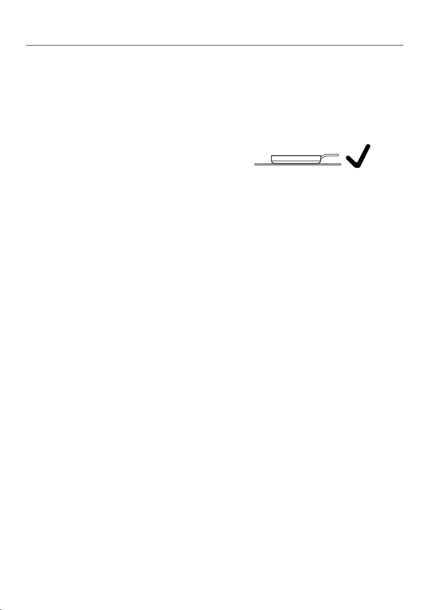
If the cookware only partially covers a cooking or extended zone,
the handle could become very hot.
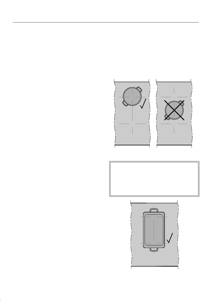
Always place cookware in the middle of a cooking or extended zone!
Only use the Flex cooking area for rectangular or oval oven
dishes.
Deposits of grease and dirt will prevent the cooker hood from
working properly.
Do not use the cooker hood without the grease filters in place. Oth-
erwise cooking vapours will not be cleaned.
There is a risk of fire if cleaning is not carried out as described in
these operating instructions.
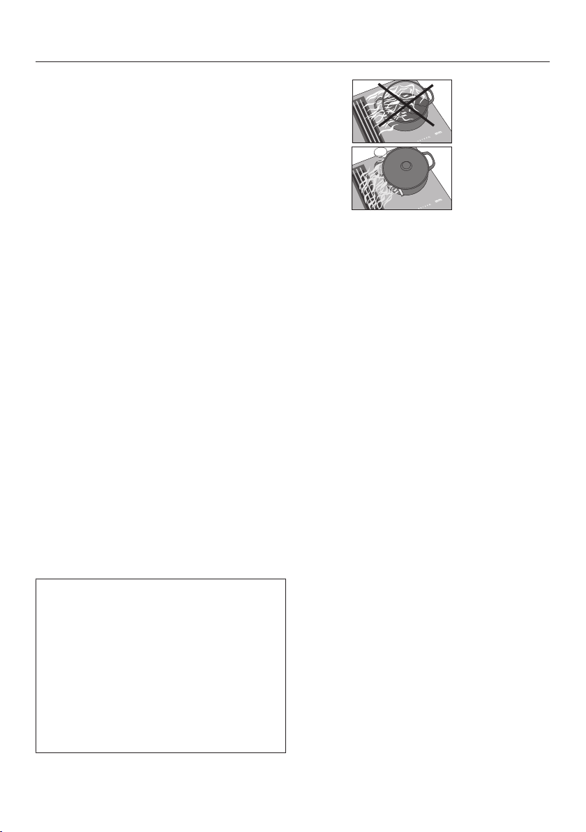
Do not cover the vapour extraction cover grille when in use.
Do not place hot cookware on the vapour extraction cover grille.
This will impair the function of the vapour extraction and may dam-
age the cover grille.
Liquids can damage the cooker hood if they get into it. Keep li-
quids away from the cooker hood.
Light objects can be drawn into the cooker hood and impair its
operation. Do not place any light objects (e.g. paper towels) within
close proximity of the cooker hood.
The induction generators could be damaged or even destroyed if
you use an induction adapter plate for cookware. Do not use induc-
tion adapter plates.

Warning and Safety instructions
18
Cleaning and care
Do not use a steam cleaning appliance to clean this hob.
The steam could reach electrical components and cause a short cir-
cuit.
If the hob is built in over a pyrolytic oven, the hob should not be
used whilst the pyrolytic process is being carried out, as this could
trigger the overheating protection mechanism on the hob (see relev-
ant section).
Accessories
Only use genuine original Miele accessories and spare parts with
this appliance. Using accessories or spare parts from other manu-
facturers will invalidate the warranty and Miele cannot accept liabil-
ity.
Miele will guarantee to supply functional spare parts for a min-
imum of 10years and up to 15years following the discontinuation of
your hob.
Caring for the environment
19
Disposing of the packaging
material
The packaging material is used for
handling and protects the appliance
from transport damage. The packaging
material used is selected from materials
which are environmentally friendly for
disposal and can generally be recycled.
Recycling the packaging material re-
duces the use of raw materials. Use
material-specific collection points for
valuable materials and take advantage
of return options. Your Miele dealer will
take the packaging material away.
Disposing of your old appli-
ance
Electrical and electronic appliances
contain many valuable materials. They
also contain certain materials, com-
pounds and components which were
essential for their correct functioning
and safety. These could be hazardous
to human health and to the environment
if disposed of with household waste or
if handled incorrectly. Please do not,
therefore, dispose of your old appliance
with household waste.
Instead, please make use of officially
designated collection and disposal
points to dispose of and recycle elec-
trical and electronic appliances in your
local community, with your dealer or
with Miele, free of charge. By law, you
are solely responsible for deleting any
personal data from the old appliance
prior to disposal. You are legally obliged
to remove any old batteries which are
not securely enclosed by the appliance
and to remove any lamps without des-
troying them, where this is possible.
These must be taken to a suitable col-
lection point where they can be handed
in free of charge. Please ensure that
your old appliance poses no risk to chil-
dren while being stored for disposal.
Guide to the appliance
20
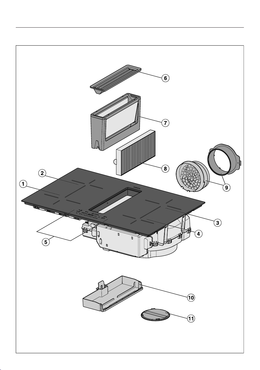
Hob

Guide to the appliance
21
aFlex cooking zone with Booster
bFlex cooking zone with Booster
can be combined with Flex cooking zone to form Flex cooking area
cFlex cooking zone with Booster
can be combined with Flex cooking zone to form Flex cooking area
dFlex cooking zone with Booster
eControls and indicators
fCover grille
gGrease filter
hCharcoal filter
KMDA 7473 FR-U, KMDA 7473 FL-U only
iPlug&Play adapter
KMDA 7473 FR-U, KMDA 7473 FL-U only
jRemovable drip tray
kCleaning flap
Guide to the appliance
22
Controls and display
f
d
c
ab
m
no ljk i h
g
e
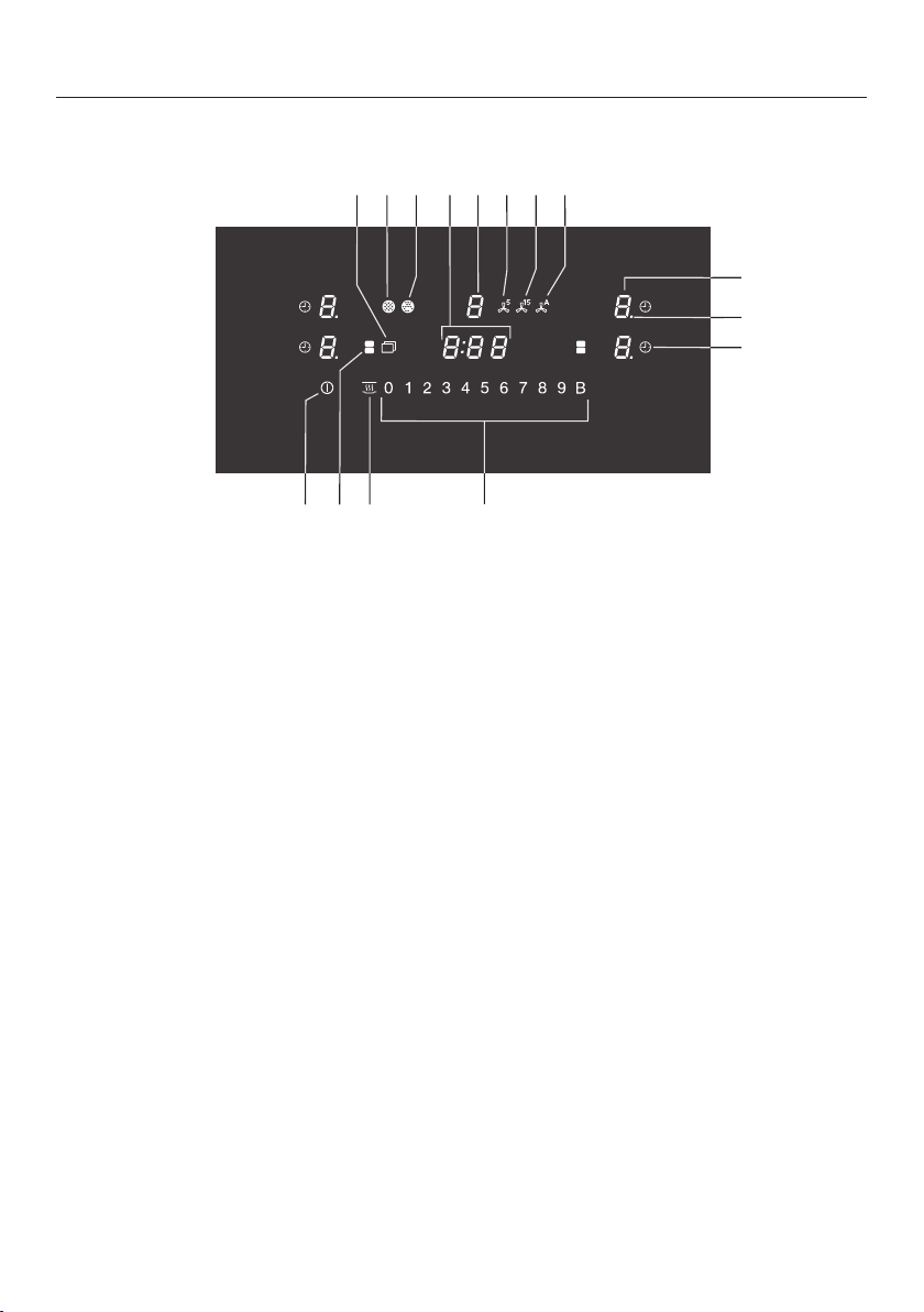
aHob On/Offsensor control
bFlex cooking zones sensor control
For manual connection/disconnection of Flex cooking zones
cKeeping warm sensor control
To activate/deactivate the Keeping warm function
dNumerical display sensor controls
– To set the power level
– To set the times
eAuto switch off sensor control
Switches the cooking zones off automatically
fPower level indicator light – extended setting range
gCooking zone selection and display sensor control
Cooking zone is ready for operation
to Power level
Residual heat
Auto heat-up
Cookware missing or unsuitable
Booster function
Keeping warm
hCon@ctivity sensor control
For activating/deactivating the Con@ctivity function of the built-in vapour ex-
traction

Guide to the appliance
23
iSensor control for the 15minute run-on option
jSensor control for the 5minute run-on option
kVapour extraction selection and display sensor control
Vapour extraction is ready for operation
to Power level
(can be changed to 3 levels)
Booster function is activated
lTimer display
: to
:
Time
System lock/safety lock is activated
Demo mode is activated
mCharcoal filter indicator light
The charcoal filter must be cleaned
nGrease filter indicator light
Grease filter must be cleaned
oMenu sensor control for displaying the following sensor controls
Wipe protection sensor control
For locking the sensor controls
Minute minder sensor control
+Entry sensor control
– For changing the programming
– For amending the times
Stop&Go sensor control
For stopping/starting a cooking process in progress
Guide to the appliance
24
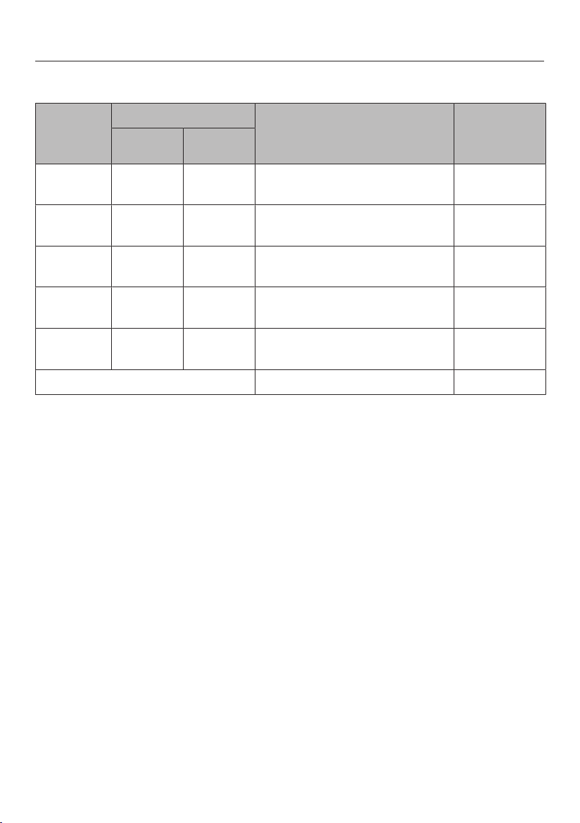
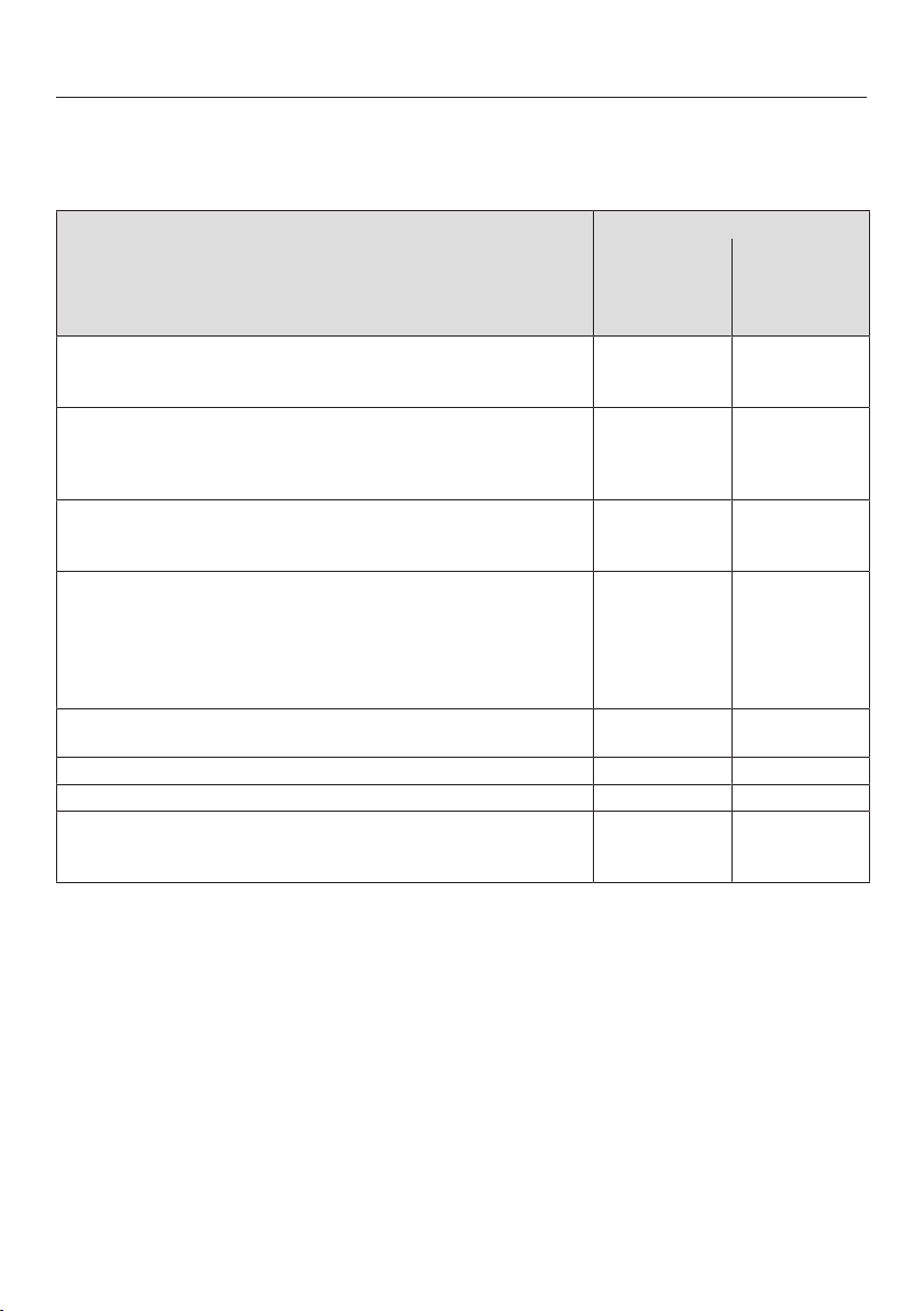
Cooking zones
Cooking
zone
Size in cm Max. rating in watts for
230V3
Linked
cooking
zone4
Ø12
11–21 21x21 Normal
Booster
2100
3000
11–21 21x21 Normal
Booster
2100
3000
11–21 21x21 Normal
Booster
2100
3000
11–21 21x21 Normal
Booster
2100
3000
+
+
– 21x42 Normal
Booster
3000
3650
-
Total 7300
1Cookware with a base diameter within the given range may be used.
2The given range corresponds to the maximum base surface of the cookware that may be used.
3The power given may vary depending on the size and material of the cookware used.
4The cooking zone is linked to this cooking zone electrically so that the rating can be increased; see
“How it works – Power management”.
Guide to the appliance
25
Accessories supplied
The accessories supplied with your ap-
pliance as well as a range of optional
ones are available to order from Miele
(see “Optional accessories”).
Drilling template
Template printed on both sides, used to
create the cut-out for the air duct or the
Plug&Play adapter.
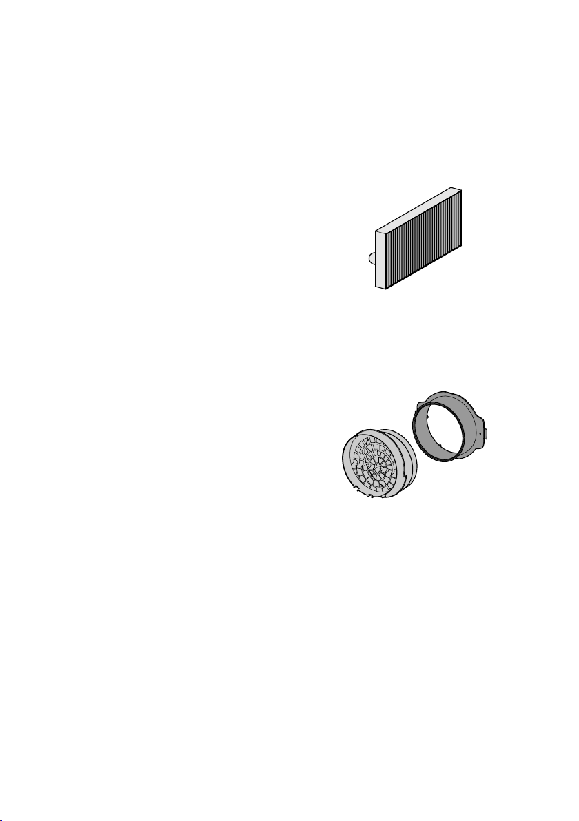
Charcoal filter
This accessory is supplied ex works
with the following KMDAs:
KMDA 7473 FR-U, KMDA 7473 FL-U
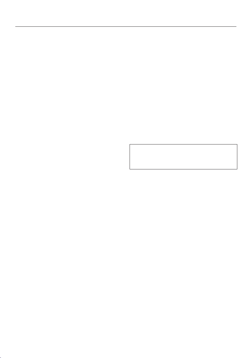
Plug&Play adapter
This accessory is supplied ex works
with the following KMDAs:
KMDA 7473 FR-U, KMDA 7473 FL-U
Before using for the first time
26
Please stick the extra data plate for
the appliance supplied with this doc-
umentation in the space provided in
the “After sales service” section of
this booklet.
Remove any protective wrapping and
stickers.
Cleaning the hob for the first
time
Before using for the first time, clean
the hob with a damp cloth only and
then wipe dry.
Switching on the hob for the
first time
The metal components have a protect-
ive coating which may give off a slight
smell when heated up for the first time.
The induction coils may also give off a
slight smell for the first few hours of op-
eration. This smell will be less notice-
able with each subsequent use before
dissipating completely.
The smell and any vapours given off do
not indicate a faulty connection or ap-
pliance and they are not hazardous to
health.
Please note that the heating up time
on induction hobs is very much
shorter than on conventional hobs.
Using the vapour extraction for
the first time
Only
KMDA 7473 FR-U, KMDA 7473 FL-U
Insert the charcoal filter (see “Clean-
ing and care – Replacing the charcoal
filter”).

Before using for the first time
27
Miele@home
Prerequisite: home WiFi network
Your hob is equipped with an integrated
WiFi module. The hob can be connec-
ted to your home WiFi network.
Make sure that the signal of your
WiFi network is sufficiently strong in
the place where your hob is installed.
There are a number of ways of connect-
ing your hob to your WiFi network.
The hob requires max. 2W in net-
worked standby.
Availability of the WiFi connection
The WiFi connection shares a frequency
range with other appliances (including
microwave ovens and remote control
toys). This can give rise to sporadic or
even complete connection failures.
Therefore, the availability of featured
functions cannot be guaranteed.
Miele@home availability
The ability to use the Miele app de-
pends on the availability of the
Miele@home service in your country.
The Miele@home service is not avail-
able in every country.
For information about availability,
please visit www.miele.com.
Miele App
The Miele App is available to download
free of charge from the Apple App
Store® or from the Google Play Store™.
After installing the Miele app on a mo-
bile device, you can do the following:
- Call up information on the operating
status of your hob
- Call up information on the pro-
gramme sequence of your hob
- Set up a Miele@home network with
other WiFi-enabled Miele appliances
Before using for the first time
28
Setting up Miele@home
Connecting via the app
The Miele app can be used to connect
to your network.
To connect, you will need:
1. Your WiFi network password
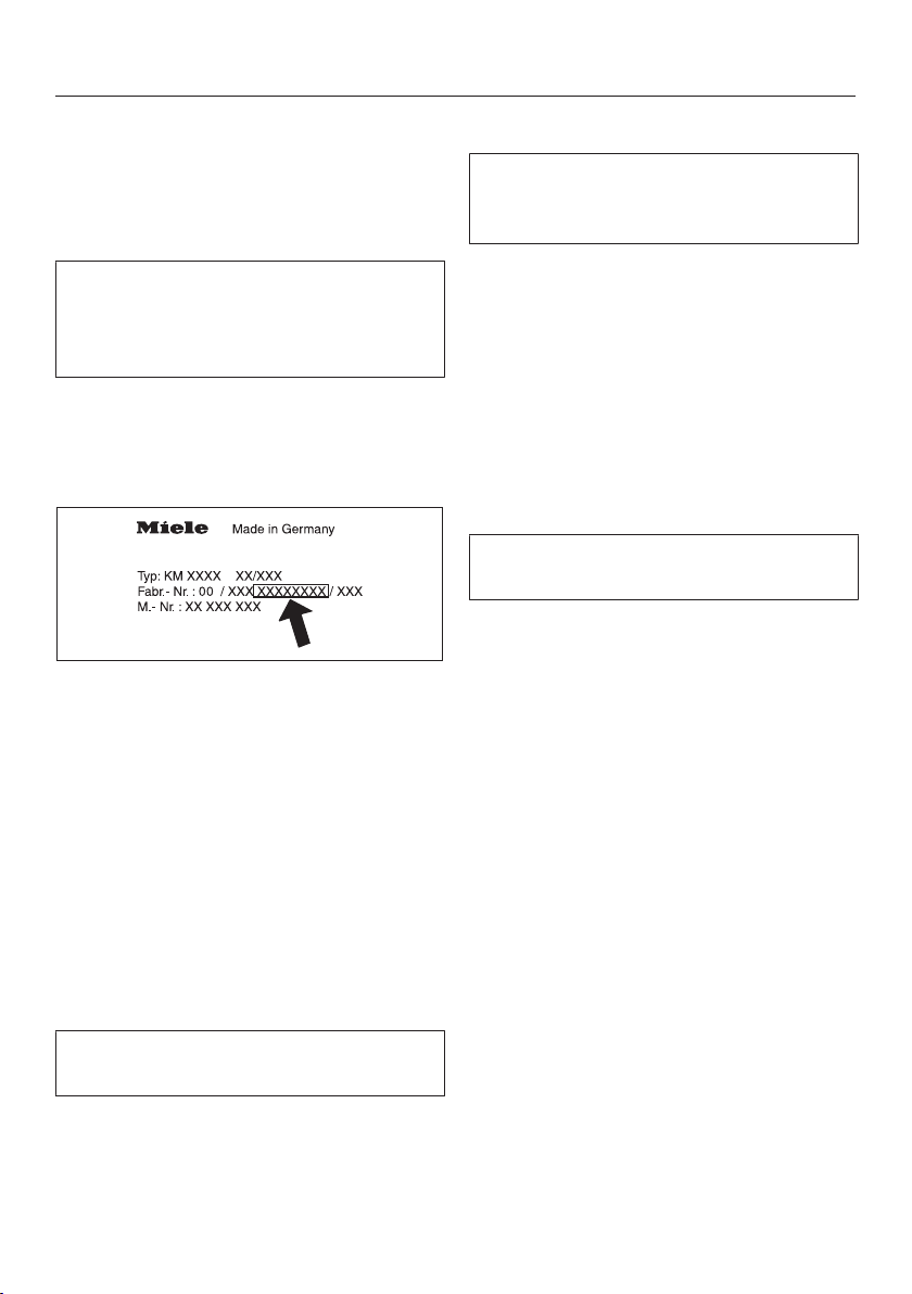
2. The password for your hob
The password for your hob consists of
the last 9digits of the serial number.
This can be found on the appliance’s
data plate.
Install the Miele app on your mobile
device.
Start the Miele app.
Switch the hob on.
Touch any cooking zone display.
Touch the0 and 5 sensor controls at
the same time for 6seconds.
The seconds can be seen counting
down in the timer display. After the time
has elapsed, the code: is displayed
in the timer display for 10seconds.
You now have 10minutes to configure
the WiFi.
Follow the user navigation in the app.
Connecting via WPS
Prerequisite: you must have a WPS
(WiFi protected setup) compatible
router.
Switch the hob on.
Touch any cooking zone display.
Touch the0 and 6 sensor controls at
the same time for 6seconds.
The seconds can be seen counting
down in the timer display. After the time
has elapsed, a progress light appears
during the connection attempt (for max.
120seconds).
The WPS login is only active during
these 120seconds.
Activate the WPS function on your
WiFi router.
If the connection was successful, the
code: appears in the timer display.
If the connection could not be estab-
lished, the timer display will show the
code:. You have probably not activ-
ated WPS on your router quickly
enough. Repeat the steps above.
Tip: If your WiFi router does not support
WPS, please connect via the Miele app.

Before using for the first time
29
Cancelling the process
Touch the sensor control.
Resetting settings
Resetting is not required when repla-
cing the router.
Switch the hob on.
Touch any cooking zone display.
Touch the0 and 9 sensor controls at
the same time for 6seconds.
The seconds can be seen counting
down in the timer display. After the time
has elapsed, the code: is displayed
in the timer display for 10seconds.
Reset the settings if you are disposing
of your hob, selling it or putting a used
hob into operation. This is the only way
to ensure that all personal data has
been removed and the previous owner
will no longer be able to access the
hob.
How it works
30
Cooking zones
An induction coil is located under each
induction cooking zone. The coil cre-
ates a magnetic field that reacts directly
with the base of the pan and heats it
up. The cooking zone itself is heated up
indirectly by the heat given off by the
pan.
An induction cooking zone only works
when cookware with a magnetic base is
placed on it (see “Cookware”). Induc-
tion automatically recognises the size of
the cookware.
Risk of burning due to hot items.
When the appliance is switched on
either deliberately or by mistake, or
when there is residual heat present,
there is the risk of metal items placed
on the hob heating up.
Do not use the appliance as a resting
place for anything.
After use, switch the hob off with
the sensor control.
Noises
When using an induction hob, the fol-
lowing noises can occur in the pan, de-
pending on what it is made of and how
it has been constructed.
Buzzing on the higher power settings.
This will decrease or cease altogether
when the power setting is reduced.
If the pan base is made of layers of dif-
ferent materials (e.g. in a sandwiched
base), it might emit a crackling sound.
Whistling might occur if linked zones
(see “Operation - Booster”) are being
used at the same time, and the pans
also have bases made of layers of dif-
ferent materials.
You might hear a clicking sound from
the electronic switches, especially on
lower settings.
A whirring sound, when the cooling fan
comes on. This switches on to protect
the electronics when the hob is being
used intensively. The cooling fan may
continue to run after the appliance has
been switched off.
How it works
31
Power management
The hob has a maximum total permitted
power consumption which cannot be
exceeded for safety reasons. You can
reduce the maximum total permitted
power consumption, see “Program-
ming”.
Cooking zones can be linked together
in pairs on the hob. This allows addi-
tional power to be transferred from one
cooking zone to another.
The values for the maximum total per-
mitted power consumption and which
cooking zones are linked together can
be found in “Overview – Cooking zone
data”.
If power is transferred from one cooking
zone (A) to the other cooking zone (B),
the power for the first cooking zone (A)
is reduced.
Example: the Booster function for cook-
ing zone (B) is activated.
If a cooking zone gives power to an-
other zone, this can have the following
effects:
- The power level is reduced.
- Auto heat-up is deactivated. Cooking
continues at the set level. If the
power is not sufficient, the power
level will be reduced again.
- The Booster function is deactivated.
- The cooking zone is switched off.
When the cooking zone stops transfer-
ring power to the other zone, the power
level can be increased again.
How it works
32
Vapour extraction
The exhaust air drawn into the vapour
extraction may only be routed directly
through the base unit in Plug&Play
mode.
Extraction mode
The air drawn in is cleaned by the
grease filter and directed outside
through a ventilation gap. The neces-
sary accessories are available from
Miele.
Guided recirculation mode
The air is drawn in and cleaned first by
the grease filter and then by a charcoal
filter. It is then directed into the recircu-
lation box via a duct. The recirculation
box feeds the air back into the kitchen.
The necessary accessories are avail-
able from Miele.
Plug&Play mode
The air is drawn in and cleaned first by
the grease filter and then by a charcoal
filter. The air is then routed through the
base unit via a cut-out in the plinth and
back into the kitchen.
A summary of the operating options
and the KMDA variants that offer them
can be found in “Installation – Operat-
ing options”.
Operating hours counter
The number of hours that the vapour
extraction has been used for is stored in
memory.
When the grease filter symbol or the
charcoal filter symbol (KMDA 7473
FR-U, KMDA 7473 FL-U only) lights up,
the operating hours counters are sig-
nalling that the filters need to be
cleaned or replaced. Further information
about cleaning and changing the filters
and resetting the operating hours coun-
ters can be found under “Cleaning and
care”.
The operating and installation instruc-
tions supplied with the recirculation
box state that the operating hours
counter for the charcoal filter needs to
be activated. This is not necessary
here.
The charcoal filter symbol also ap-
pears when the vapour extraction is
operated using extraction mode.

Pans
33
Suitable cookware
- Stainless steel cookware with a mag-
netic base
- Enamelled steel cookware
- Cast iron
Please be aware that the properties of
the cookware base can affect the even-
ness with which the food heats up (e.g.
when making pancakes). The base of
the pan must be able to distribute the
heat evenly. Cookware with a base
made from multilayer material (sand-
wich or encapsulated base) is ideal in
this case.
Unsuitable pans.
- stainless steel pans without a mag-
netic base
- aluminium or copper pans
- glass, ceramic or earthenware pots
and pans
Testing pans
To test whether a pan is induction-com-
patible, hold a magnet to the base of
the pan. If the magnet sticks, the pan is
generally suitable.
No cookware/unsuitable cook-
ware display
Thesymbol flashes alternately with
the power level selected in one of the
cooking zone displays if:
- The cooking zone has been switched
on without cookware in place, or if
the cookware is unsuitable (non-
magnetic base).
- The diameter of the base of the cook-
ware is too small.
- The cookware is taken off the cook-
ing zone when it is switched on.
If no cookware or unsuitable cookware
is placed on the cooking zone, the
cooking zone will switch off automatic-
ally after 3minutes.
Using the cooking zone
Place a suitable item of cookware on
the cooking zone within 3minutes.
switches off. The cooking process is
continued with the previously selected
settings.
If you are using a different item of
cookware and/or food, modify the
settings.
Not using the cooking zone
Switch the cooking zone off.
Pans
34
Tips
- To make optimum use of the cooking
zones, choose cookware with a suit-
able base diameter (see “Overview –
Cooking zone data”). If an item of
cookware is too small, it will not be
recognised.
- Position the cookware as centrally as
possible on the relevant cooking
zone/cooking area.
- Use only cookware with smooth
bases. Rough bases can scratch the
ceramic glass.
- Always lift cookware to move it. This
will help prevent scratching. If any
scratches do appear as a result of
cookware being pushed around, this
will not affect the function of the hob.
These scratches are normal signs of
use and are not grounds for making a
complaint.
- Please note that the cookware dia-
meter quoted by manufacturers often
refers to the maximum diameter or
diameter of the top rim. The diameter
of the base (generally smaller) is more
important.
- Where possible, use cookware with
vertically straight sides. If an item of
cookware has angular sides, induc-
tion also acts on the sides of the item
of cookware. The sides of the item of
cookware may discolour or the coat-
ing may peel off.

Tips on saving energy
35
- Cook in covered pots and pans if
possible. This prevents heat escaping
unnecessarily.
- Cook with as little water as possible.
- When you have brought the pan to
the boil, switch to a lower power level
as soon as possible.
- Use a pressure cooker to reduce
cooking durations.
- It is important to ensure that the kit-
chen is well ventilated during opera-
tion. In extraction mode if there is in-
sufficient air flow, the cooker hood
cannot operate efficiently and this
causes increased operating noise
levels.
- Always cook with the lowest possible
setting. This produces fewer cooking
vapours, so you can use a lower
power level and therefore benefit
from reduced energy consumption.
- Check the power level on the cooker
hood. A low power level is usually
sufficient. Only use the Booster set-
ting when necessary.
- When a large volume of cooking va-
pours are being produced, switch to
a high power level in good time. This
is more efficient than operating the
cooker hood for longer to try to cap-
ture cooking vapours which have
already been distributed throughout
the kitchen.
- Switch the cooker hood off after
cooking.
- Clean or replace the filters at regular
intervals. Heavily soiled filters reduce
performance, increase the risk of fire
and are unhygienic.
Setting ranges
36
The hob is programmed with 9power levels at the factory. If you wish to fine-tune
a setting, you can extend the power level range to 17power levels (see “Program-
ming”).
Setting range
Factory set-
ting
(9power
levels)
Extended set-
ting
(17power
levels)
Melting butter
Melting chocolate
Dissolving gelatine
1–2 1–2.
Warming up small quantities of liquid
Keeping warm food which sticks easily
Cooking rice or porridge
Defrosting vegetables frozen in a block
2–4 2–3.
Warming up liquid and semi-solid food
Steaming fruit
Simmering potatoes (cookware with lids)
4–6 3.–5.
Making omelettes or lightly fried eggs
Gently frying meat patties
Steaming fish and vegetables
Cooking dumplings and dried pulses
Defrosting and reheating frozen food
Thickening sauces, e.g. Hollandaise
5–7 4.–7.
Gently frying fish, escalopes, sausages, fried eggs (without
overheating the fat)
6–8 6–7.
Cooking potato fritters, pancakes, etc. 7–8 7–8.
Frying, e.g. chips 9 8.–9
Boiling large quantities of water
Bringing to the boil
Searing large quantities of meat
9–Booster 8.–Booster
These settings should only be taken as a guide. The power of the induction coils will vary
depending on the size and material of the cookware. For this reason, it is possible that the
power levels will need to be adjusted slightly to suit your cookware. As you use the hob,
you will get to know which settings suit your cookware best. When using new cookware
that you are not familiar with, set the power to one level below the one specified.
Operation
37
Using the appliance
This ceramic glass hob is equipped with
electronic sensor controls which react
to finger contact. For safety reasons, in
order to switch the appliance on, the
On/Off sensor control needs to be
touched for a little longer than the other
sensors.
Each time a sensor control is activated,
an audible signal sounds.
Only the printed On/Offsymbol is
visible when the hob is switched off.
More sensors light up when the hob is
switched on.
In order to set or alter a power level, the
cooking zones must be “active”. To ac-
tivate a cooking zone, touch the display
for the relevant cooking zone. The rel-
evant cooking zone display will appear
brighter when touched. While the dis-
play is brighter, the cooking zone is
“active” and you can set a power level
or time.
Exception: if only one of the cooking
zones is in operation, you can alter the
power level without activating the cook-
ing zone.
Malfunction due to dirty and/or
covered sensor controls.
If the sensor controls are dirty or
covered, this could cause them to
fail to react, to activate a function or
even to switch the appliance off
automatically (see “Safety features –
Safety switch-off”). Placing hot
cookware on the sensor controls/in-
dicators can damage the electronic
unit underneath.
Keep the sensor controls and indic-
ators clean.
Do not place anything over the
sensor controls or indicators.
Do not place hot cookware over the
sensor controls or indicators.
Operation
38
Risk of fire with overheated food.
Unattended food can overheat and
catch alight.
Do not leave the hob unattended
whilst it is being used.
Please note that the heating up time
on induction hobs is very much
shorter than on conventional hobs.
Switching on the hob
Touch the sensor.
Other sensors will light up.
If no further entry is made, the hob will
switch itself off after a few seconds for
safety reasons.
Setting the power level
Permanent pan recognition is activ-
ated as standard (see “Programming”).
When the hob is switched on and you
place an item of cookware on one of
the cooking zones, all the sensors for
that cooking zone’s numerical display
will light up.
Place the cookware on the cooking
zone you want to use.
Touch the appropriate sensor control
on the numerical display for the
power level you want.
Changing the power level
Touch the relevant cooking zone dis-
play.
The cooking zone display appears
brighter.
Touch the appropriate sensor control
on the numerical display for the
power level you want.
Switching off a cooking zone/
the hob
Switching off a cooking zone
Touch and hold the relevant cooking
zone display until the cooking zone
switches off.
or
Touch the relevant cooking zone dis-
play.
The cooking zone display appears
brighter.
Touch the 0sensor control on the nu-
merical display.
Switching the hob off
To switch off the hob and all the
cooking zones, touch the sensor
control.
Operation
39
Residual heat indicator
If the cooking zone is still hot, the resid-
ual heat indicator will light up after it
has been switched off.
The bars of the residual heat indicator
go out one after the other as the cook-
ing zone cools down. The last hori-
zontal bar only goes out when the
cooking zone is safe to touch.
Risk of burning due to hot cook-
ing zones.
The cooking zones will be hot after
use.
Do not touch the cooking zones
while the residual heat indicators are
on.
Setting the power level – ex-
tended setting range
Touch the numerical display in
between two number sensors.
A dot appears after the power level in
the cooking zone selection.
The sensor controls to the left of the in-
terim level light up brighter than the
other sensor controls.
Example:
If you have set power level 7., the cook-
ing zone selection will show 7..
The number 7 on the numerical display
will light up brighter than the other
sensor controls.
Operation
40
Flex cooking area
The Flex cooking zones combine auto-
matically to form a Flex cooking area
when you place sufficiently large items
of cookware on them (see “Guide to the
appliance – Hob”). The Flex cooking
zones can also be connected or discon-
nected manually:
Touch the sensor control.
Positioning cookware
Refer to the cooking zone data for your
hob model for information about cook-
ware sizes and the corresponding posi-
tions (see “Overview – Cooking zone
data”).
Flex cooking zone
Flex cooking area (oven dishes)
Oven dishes with a base length of
less than 25cm may not be detected
by the cooking area.
Place oven dishes of this size on an
individual cooking zone.

Operation
41
Auto heat-up
When Auto heat-up has been activated,
the cooking zone switches on automat-
ically at the highest setting and then
switches to the continued cooking set-
ting which you have previously selec-
ted. The heat-up time depends on
which continued cooking setting has
been chosen (see chart).
Activating Auto heat-up
Briefly touch the display for the re-
quired cooking zone.
Touch the sensor for the continued
cooking setting you want until a tone
sounds and lights up in the cooking
zone display.
The symbol flashes alternately with
the power setting selected in the cook-
ing zone display during the heat-up
time (see chart).
Changing the continued cooking set-
ting while the cooking zone is heating
up deactivates Auto heat-up.
Deactivating Auto heat-up
Touch the sensor for the continued
cooking setting.
or
Set another power level.
Continued cook-
ing setting*
Heat-up time
[min:sec]
1 Approx. 0:15
1. Approx. 0:15
2 Approx. 0:15
2. Approx. 0:15
3 Approx. 0:25
3. Approx. 0:25
4 Approx. 0:50
4. Approx. 0:50
5 Approx. 2:00
5. Approx. 5:50
6 Approx. 5:50
6. Approx. 2:50
7 Approx. 2:50
7. Approx. 2:50
8 Approx. 2:50
8. Approx. 2:50
9 –
* The continued cooking settings with a dot
after the number are only available if the
power level range has been extended (see
“Programming”).
Operation
42
Booster function
When the Booster function is activated,
the power is boosted so that large
quantities can be heated up quickly,
e.g. when boiling water for cooking
pasta. The boost in power is active for a
maximum of 5minutes.
When the Booster function is activ-
ated, the settings for the linked cook-
ing zone may be changed, see “Induc-
tion – Power management”.
The Booster function can be used on a
maximum of 2 cooking zones or 1 Flex
cooking area at the same time.
If the Booster function is switched on
when
- no power level has been selected,
the cooking zone will revert automat-
ically to level9 at the end of the
Booster time or if the Booster func-
tion is switched off before this.
- a power level has been selected, the
cooking zone will revert automatically
to the power level selected at the end
of the Booster time or if the Booster
function is switched off before this.
Activating the Booster
Place the cookware on the cooking
zone you want to use.
Select a power level if necessary.
Touch the Bsensor control.
will appear in the cooking zone dis-
play.
Deactivating the Booster
Touch the Bsensor control.
or
Set another power level.

Operation
43
Keeping warm
This function is for keeping food warm
which has just been cooked and is still
hot. It is not for reheating food that
has gone cold.
The maximum duration for keeping food
warm is 2 hours.
- Only use pans for keeping food
warm. Cover the pan with a lid.
- Stir firm or viscous food (mashed
potatoes, stew) occasionally.
- Nutrients are lost when food is
cooked, and continue to diminish
when food is kept warm. The longer
food is kept warm, the greater the
loss of nutrients. Try to ensure that
food is kept warm for as short a time
as possible.
Activating/deactivating the Keeping
warm function
Touch the cooking zone display for
the required cooking zone.
The cooking zone display appears
brighter.
Touch the sensor control.
Operation
44
Vapour extraction
The vapour extraction will switch itself
on automatically if there is an item of
cookware on a cooking zone and a
power level has been set for that zone
(Con@ctivity). The power level for va-
pour extraction is set to suit the power
level of the cooking zone. The run-on
time and level depend on the power
level of the vapour extraction.
You can deactivate Con@ctivity tempor-
arily or permanently. To deactivate
Con@ctivity permanently, see “Pro-
gramming”. If Con@ctivity is perman-
ently deactivated, the sensor control
will no longer be illuminated.
The power level of the vapour extraction
can be manually altered at any time.
Power levels 1 to 3 and a Booster level
are set as standard. The power levels
can be extended to 1 to 9 and a
Booster level, see “Programming”.
For light to heavy cooking vapours and
odours, select from power levels 1 to 3
(9 with the extended power levels). For
short periods of very strong vapours
and odours, e.g. whilst searing meat,
select the B Booster setting.
If the vapour extraction starts with
power level1, the power is automatic-
ally increased to level2 for
20seconds. The increase in power is
necessary in order to ensure that the
flap opens in extraction mode. If you
are using the vapour extraction in re-
circulation mode, you can deactivate
this automatic function, see “Program-
ming”.
Tip: To help release vapours effectively
with pans over 15cm high, place a
wooden spoon between the lid and the
pan.
Operation
45
Setting the power level/Switching off
vapour extraction
Touch the vapour extraction display.
To switch the fan on touch the appro-
priate sensor for the power level you
want.
To switch the fan off touch the 0
sensor.
If the vapour extraction is not switched
off manually, it will switch itself off
automatically 12hours after last being
used.
Deactivating Con@ctivity temporarily
The vapour extraction has switched on
automatically.
You can deactivate Con@ctivity in
various ways:
- Touch the sensor control
- Touch the 0sensor control
- Select a different power level
Set the power level you want.
Depending on the programming,
Con@ctivity will be reactivated when
you switch the hob off and back on
again, see “Programming”.
If you want to deactivate Con@ctivity
permanently, you will need to change
the Con@ctivity programming, see
“Programming”.
Booster
The maximum duration for the Booster
is 10minutes.
To switch it off early, set a different
power level.
Run-on time
It is advisable to run the fan for a few
minutes after cooking has finished. This
helps to neutralise any lingering va-
pours and odours in the air. The follow-
ing two options are available:
(5minutes) and (15minutes).
The run-on duration will be carried out
using the power level set during activa-
tion. You can change the power level
during the run-on period.
Touch the or sensor to activate
the run-on period.
Touch the, or 0 sensor to deac-
tivate the run-on period.
If you switch the hob off with the
sensor, the run-on period will continue
through to the end.

Timer
46
The hob has to be switched on if you
want to use the timer.
The timer can be used for the following
2 functions:
- For setting the minute minder
- For automatically switching a cooking
zone off
You can use the functions simultan-
eously.
A duration of between 1minute(:)
and 9hours 59minutes(:) can be
set.
Durations of up to 59minutes are
shown in minutes (00:59) and durations
of more than 60minutes are shown in
hours and minutes. Durations are
entered in the order of hours, followed
by minutes in tens and then units.
Durations are entered using the numer-
ical display and can be adjusted with
the + sensor control.
Example:
59 minutes = 0:59 hours,
Enter: 5-9
80 minutes = 1:20 hours,
Enter: 1-2-0
After the first number has been entered,
the timer display will light up constantly.
After the second number has been
entered, the first number will move to
the left. After the third number has been
entered, the first and second numbers
will move to the left.
Minute minder
Setting the minute minder
Touch the sensor control.
Touch the sensor control.
The timer display flashes.
Set the required duration.
Touch the sensor control or wait
10seconds to start the minute minder.
Changing the minute minder duration
Touch the sensor control.
The timer display flashes.
Set the required duration.
Deleting the minute minder duration
Touch the sensor control.
Touchon the numerical display.
Timer
47
Auto switch off
You can set a time after which a cook-
ing zone will switch off automatically.
This function can be used for all cook-
ing zones at the same time.
If the time programmed is longer than
the maximum operating time allowed,
the cooking zone will be switched off
by the safety switch-off function (see
“Safety features – Safety switch-off”).
Setting the switch-off time
Select a power level for the cooking
zone you require.
Touch the sensor control next to
the relevant cooking zone display.
The timer display flashes.
Set the required duration.
Touch the sensor control or wait
10seconds to start the switch-off time.
The sensor control lights up con-
stantly.
To set a switch-off time for another
cooking zone, follow the same steps
as described above.
If multiple switch-off times are pro-
grammed, the timer for the most re-
cently selected cooking zone is dis-
played. The sensor control next to
the relevant cooking zone display
lights up brighter.
If you want to show the time left for
another cooking zone which is count-
ing down in the background, touch
the sensor control for the desired
cooking zone.
Changing the switch-off time
Touch the required cooking zone dis-
play.
Touch the sensor control next to
the relevant cooking zone display.
The timer display flashes.
Set the required duration.
Deleting the switch-off time
Touch the required cooking zone dis-
play.
Touch the sensor control of the re-
quired cooking zone until the
:symbol appears in the timer dis-
play.
or
Touch the sensor control next to
the relevant cooking zone display.
The timer display flashes.
Touch the sensor control on the nu-
merical display.

Timer
48
Using both timer functions at
the same time
If you use both functions at the same
time, the time of the last selected func-
tion is always displayed.
Touch the sensor control or the rel-
evant cooking zone display if you
want to show the times left counting
down in the background.
Additional functions
49
Stop&Go
When Stop & Go is activated, the power
of all cooking zones in use is reduced to
power level1. The power level of the
vapour extraction is not reduced. De-
pending on the power level set for the
cooking zones, it may even increase.
The cooking zone power levels and the
timer settings cannot be altered; the
hob can only be switched off. The
minute minder, switch-off, Booster and
heat-up times continue to run.
When Stop&Go is deactivated, the
cooking zones will operate at the power
level previously selected.
If the function is not deactivated within
1hour, the hob will switch off.
Activating
Touch the sensor control.
Touch the sensor control.
Deactivating
Touch the sensor control.
Use this function if there is a danger of
food boiling over.
Recall
If the hob is switched off by mistake
during use, this function can be used to
reset all settings. For this to work, the
hob must be switched on again within
10seconds of being switched off.
Switch the hob on again.
Immediately after switching the hob
on, touch one of the flashing cooking
zone displays.

Additional functions
50
Wipe protection
The hob sensor controls can be
locked for 20seconds, e.g. to remove
soiling. The sensor control is not
locked.
Activating
Touch the sensor control.
Touch the sensor control.
The time counts down in the timer dis-
play.
Deactivating
Touch the sensor control until the
timer display goes out.
Demo mode
These functions enable the hob to be
demonstrated in showrooms without
heating up.
Activating/deactivating demo mode
When this mode is set, the hob can be
operated as normal.
Switch the hob on.
Place an induction-compatible item
of cookware on the hob.
Touch and hold the 0 and 2sensor
controls on the numerical display at
the same time for 6seconds.
In the timer display, flashes altern-
ately with (demo mode activated)
or (demo mode deactivated) for a
few seconds.
Displaying hob data
The model number and software ver-
sion of the hob can be displayed.
Model number/serial number
Switch the hob on.
Place an induction-compatible pan
on the hob.
Touch and hold the0 and 4 sensor
controls on the numerical display at
the same time.
Numbers will appear in the timer display
one after another, separated by a dash.
Example: (model number
KM1234)– (serial num-
ber)
Software version
Switch the hob on.
Place an induction-compatible pan
on the hob.
Touch and hold the0 and 3 sensor
controls on the numerical display at
the same time.
Numbers appear in the timer display:
Example: : = software version2.00

Safety features
51
System lock/safety lock
The safety lock function is deactiv-
ated if there is a mains outage.
Your hob is equipped with a system
lock and a safety lock to prevent the
hob, cooking zones and vapour extrac-
tion being switched on inadvertently or
any settings being altered.
The system lock is activated when the
hob is switched off. If the system lock is
activated, the hob cannot be switched
on and the timer cannot be used. A set
minute minder time continues to count
down. The hob is programmed so that
the system lock must be activated
manually. The system lock can be pro-
grammed to be activated automatically
5minutes after the hob has been
switched off (see “Programming”).
The safety lock is activated when the
hob is switched on. When the safety
lock is activated, the hob can be oper-
ated only under certain conditions:
- The cooking zones, the vapour ex-
traction and the hob can only be
switched off.
- The sensor control can be activ-
ated.
- A set minute minder time can be
modified.
If an unavailable sensor control is
touched whilst the system lock or
safety lock is activated will appear
in the timer display for a few seconds
and a tone will sound.
Activating the system lock
Touch the sensor control for
6seconds.
The seconds can be seen counting
down in the timer display. When this
time has elapsed will appear in the
timer display. The system lock is activ-
ated.
Deactivating the system lock
Touch the sensor for 6seconds.
will appear briefly in the timer dis-
play and then the seconds will be seen
counting down. The system lock is de-
activated once the time has elapsed.
Activating the safety lock
Touch the sensor control.
Touch and hold the and sensor
controls at the same time for
6seconds.
The seconds can be seen counting
down in the timer display. When this
time has elapsed will appear in the
timer display. The safety lock is activ-
ated.
Deactivating the safety lock
Touch and hold the and sensor
controls at the same time for
6seconds.
will appear briefly in the timer dis-
play and then the seconds will count
down. Once the time has elapsed, the
safety lock function is deactivated.

Safety features
52
Safety switch-off
Sensor controls are covered
Your hob will turn off automatically if
one or several of the sensors remain
covered for longer than 10 seconds, for
example, by finger contact, food boiling
over or by an object such as an oven
glove or tea towel. will flash briefly in
the timer display and a tone will sound.
will go out once you have removed
the object and/or cleaned the hob and
the hob will be ready to use again.
Excessive operating time
The safety switch-off mechanism is
triggered automatically if a cooking
zone is heated for an unusually long
period of time. This time depends on
the power level selected. If it has been
exceeded, the cooking zone switches
off and the residual heat indicator ap-
pears. If you switch the cooking zone
on and off again, it is ready for opera-
tion again.
The hob is programmed to safety set-
ting0 at the factory. If required you
can set a higher safety setting with a
shorter maximum operating time (see
chart).
Power level* Maximum operating time
[h:min]
Safety setting
0** 1 2
1 10:00 8:00 5:00
1. 10:00 7:00 4:00
2/2. 5:00 4:00 3:00
3/3. 5:00 3:30 2:00
4/4. 4:00 2:00 1:30
5/5. 4:00 1:30 1:00
6/6. 4:00 1:00 0:30
7/7. 4:00 0:42 0:24
8 4:00 0:30 0:20
8. 4:00 0:30 0:18
9 1:00 0:24 0:10
* The power levels with a dot after the num-
ber are only available if the power level
range has been extended (see “Setting
ranges”).
** Factory default setting

Safety features
53
Overheating protection
All the induction coils and heat sinks for
the electronic module are fitted with an
overheating protection mechanism. Be-
fore the induction coils or heat sinks get
too hot, the overheating protection
mechanism intervenes in one of the fol-
lowing ways:
Induction coils
- Any Booster function in operation will
be switched off.
- The set power level will be reduced.
- The cooking zone turns off automat-
ically. will flash alternately
within the timer display.
You can use the cooking zone again as
usual when the fault message has gone
out.
Heat sinks
- Any Booster function in operation will
be switched off.
- The set power level will be reduced.
- The cooking zones switch off auto-
matically.
The affected cooking zones can only be
used again as usual once the cooling
element has cooled down to a safe
level.
The overheating protection may be ac-
tivated under the following circum-
stances:
- The cookware being heated is empty.
- Fat or oil is being heated on a high
power level.
- There is insufficient ventilation to the
underside of the hob.
- A hot cooking zone is switched back
on after an interruption to the power
supply.
If, despite removing the cause, the
overheating protection mechanism trig-
gers again, contact customer service.

Programming
54
You can adapt the programming of the
hob to your personal needs. Several
settings can be altered in succession.
After accessing programming mode,
the + sensor and will appear in the
timer display. After a few seconds :
(Programme 01) will flash alternately
with : (Code) in the timer display.
Changing the programming
Accessing programming mode
With the hob switched off, touch
and hold the and sensors to-
gether until the + sensor lights up and
appears in the timer display.
Setting the programme
For a two-digit programme number
you need to first set the tens position.
Whilst the programme is visible in the
display (e.g. :), touch the +sensor
repeatedly until the number for the
programme you want appears in the
display or touch the appropriate num-
ber on the numerical display.
Setting the code
Whilst the code is visible in the dis-
play (e.g. :), touch the+sensor re-
peatedly until the number for the
code you want appears in the display
or touch the appropriate number on
the numerical display.
Saving the settings
Whilst the programme is visible in the
display (e.g.:), touch the
sensor until the indicators go out.
To avoid saving the settings
While the code is showing in the dis-
play (e.g. :) touch the sensor
until the indicators go out.
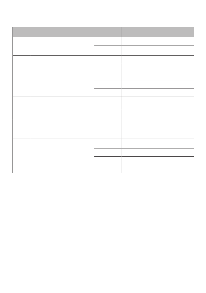
Programming
55
Programme1Code2Settings
P:01 Demo mode C:00 Demo mode off
C:01 Demo mode on3
P:02 Power management4C:00 Off
C:01 3680W
C:02 3000W
C:03 2000W
C:04 1000W
P:03 Factory default settings C:00 Do not restore factory default set-
tings
C:01 Restore factory default settings5
P:04 Number of cooking zone power
levels
C:00 9 power levels + Booster
C:01 17 power levels + Booster6
P:06 Audible tone when a sensor
control is touched
C:00 Off7
C:01 Quiet
C:02 Medium
C:03 Loud
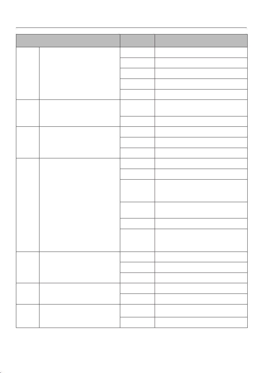
Programming
56
Programme1Code2Settings
P:07 Timer buzzer C:00 Of
C:01 Quiet
C:02 Medium
C:03 Loud
C:04 Maximum volume
P:08 System lock C:00 System lock can only be activated
manually
C:01 System lock activated automatically
P:09 Maximum operating time C:00 Safety setting 0
C:01 Safety setting 1
C:02 Safety setting 2
P:10 WiFi registration C:00 Not active/deactivated
C:01 Active but not configured
C:02 Active and configured (cannot be se-
lected; displays whether connection
was successful)
C:03 Connection possible via WPS push
button
C:04 WiFi reset to default (C:00)
C:05 Direct WiFi connection of hob and
external cooker hood without Miele
app (Con@ctivity3.0)
P:12 Sensor controls reaction speed C:00 Slow
C:01 Normal
C:02 Fast
P:15 Permanent pan recognition C:00 Permanent pan recognition off
C:01 Permanent pan recognition on
P:16 Con@ctivity of built-in vapour
extraction
C:00 Con@ctivity off8
C:01 Con@ctivity on
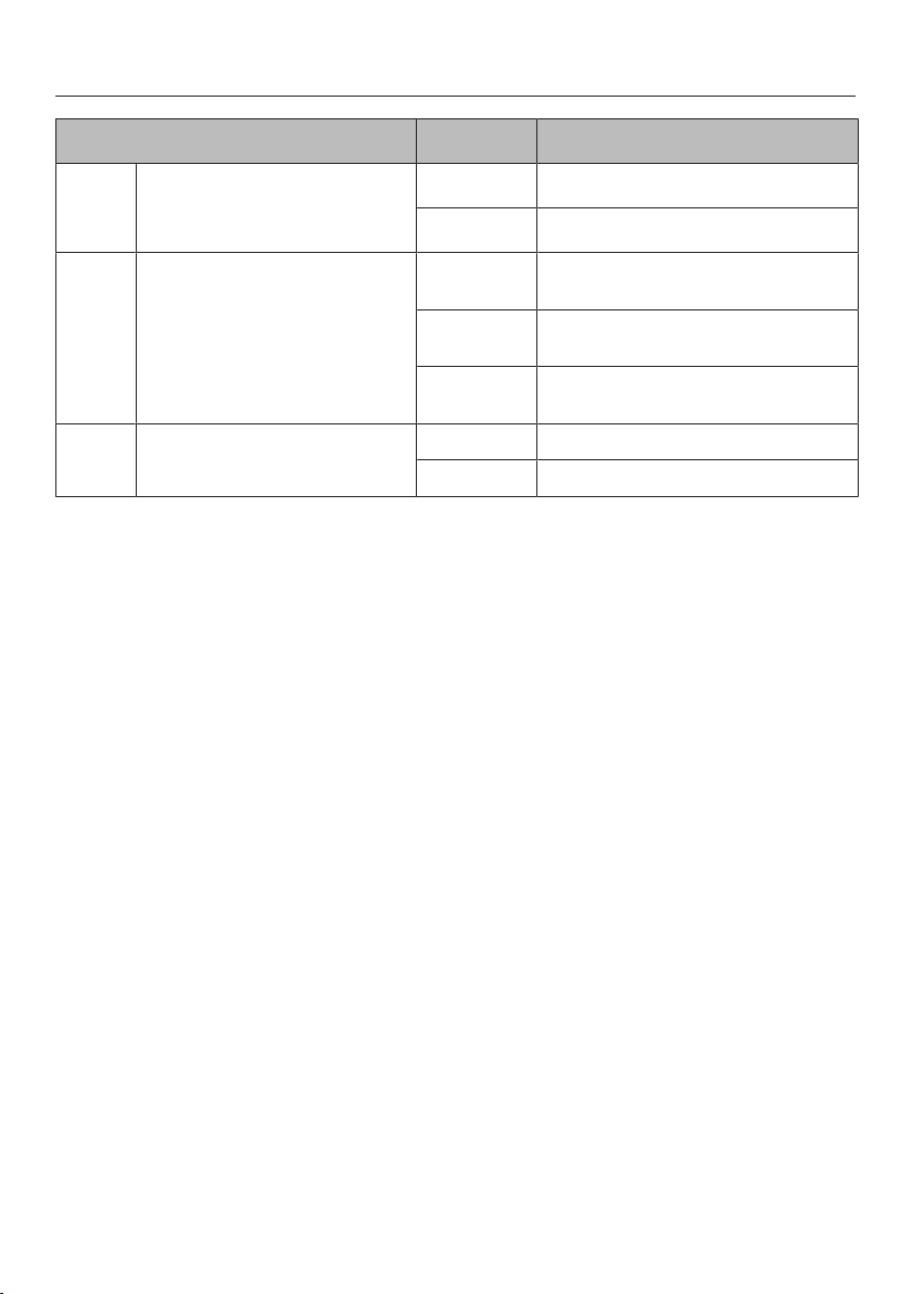
Programming
57
Programme1Code2Settings
P:17 Vapour extraction operating
mode C:009Recirculation mode
C:019Extraction mode
P:18 Start settings of Con@ctivity10 C:00 Always start with Con@ctivity deac-
tivated
C:01 Always start with Con@ctivity activ-
ated
C:02 Start with the most recently set
Con@ctivity state
P:19 Number of vapour extraction
power levels
C:00 3 power levels + Booster
C:01 9 power levels + Booster
1Programmes not shown here have no allocation.
2The factory default setting is shown in bold.
3After the hob has been switched on, appears in the timer display for a few seconds.
4The total output of the hob may be reduced in order to meet the local network provider’s
requirements.
5The settings for the P:17 operating mode of the vapour extraction will not be reset to the
factory default settings.
6In the text and tables, the extended power levels are shown with a dot after the number.
7The confirmation tone of the On/Offsensor control cannot be switched off.
8 Plug&Play mode: Con@ctivity is required for correct operation.
9Factory-set code:
KMDA 7473 FR-U, KMDA 7473 FL-U: C:00
KMDA 7473 FR-A, KMDA 7473 FL-A: C:01
10The settings only take effect if Con@ctivity has been activated in the P:16 programme.
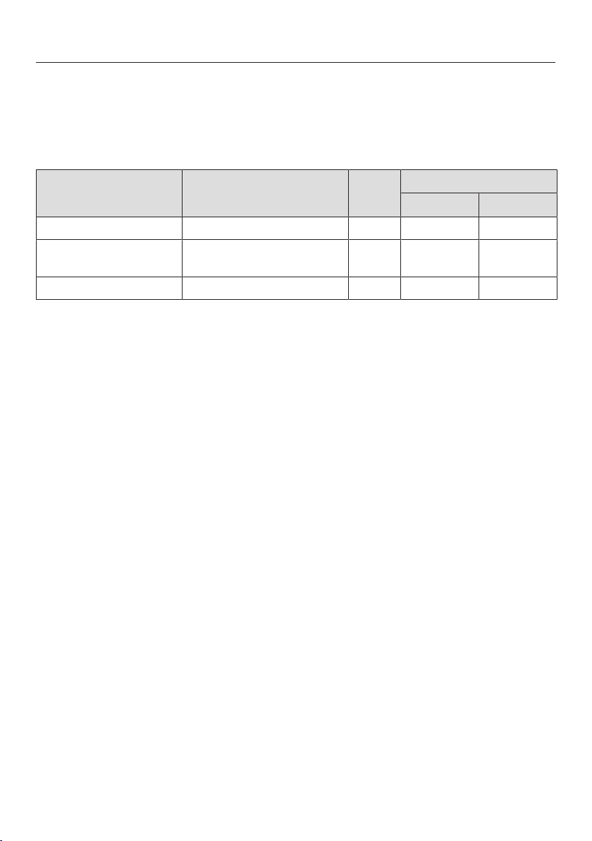
Note for test institutes
58
Test food acc. to EN60350-2
9 power levels are programmed at the factory.
For testing in accordance with the above standard, programme the hob to the ex-
tended power level setting.
Test food Pan base (mm) Lid
Power level
Pre-heat Cooking
Heating oil up 150 No – 1–2
Pancakes 180
(Sandwich base)
No 9 5.–7.
Frying deep frozen chips According to the standard No 9 9
Cleaning and care
59
Risk of burning due to hot cook-
ing zones.
The cooking zones will be hot after
use.
Switch the hob off.
Allow the cooking zones to cool
down before cleaning the hob.
Risk of injury due to the fan mo-
tor.
The fan motor rotates while the va-
pour extraction is active.
Switch the hob off.
Wait until the run-on cycle is fin-
ished, if applicable.
Risk of damage due to moisture
ingress.
The steam from a steam cleaning ap-
pliance could reach live electrical
components and cause a short cir-
cuit.
Do not use a steam cleaner to clean
the hob.
All surfaces could be discoloured or
damaged if unsuitable cleaning
agents are used. All surfaces are
susceptible to scratching.
Remove all cleaning agent residues
immediately.
Never use abrasive sponges or
cleaning agents.
Allow the hob to cool down before
cleaning.
Clean the hob after every use.
Dry the hob thoroughly after cleaning
with water to avoid limescale residue.
Unsuitable cleaning agents
To avoid damaging the surfaces of the
appliance, do not use:
- Washing-up liquid
- Cleaning agents containing soda, al-
kalines, ammonia, acids or chlorides
- Cleaning agents containing descaling
agents
- Stain and rust removers
- Abrasive cleaning agents, e.g.
powder cleaners and cream cleaners
- Cleaning agents containing solvents
- Dishwasher cleaners
- Oven sprays
- Glass cleaning agents
- Hard, abrasive brushes
- Sponges
- Eraser stain remover blocks
Cleaning and care
60
Cleaning the ceramic surface
Risk of damage by pointed ob-
jects.
The seal between the hob and the
worktop could suffer damage.
The seal between the ceramic sur-
face and the frame could suffer dam-
age.
Do not use pointed objects for clean-
ing.
Not all soiling and residues can be
removed using a solution of wash-
ing-up liquid. An invisible film can
develop that can lead to discoloura-
tion of the glass ceramic surface.
This discolouration cannot be re-
moved.
Clean the ceramic surface regularly
with a proprietary ceramic glass
cleaning agent.
Remove any coarse soiling with a
damp cloth and more stubborn soil-
ing with a shielded scraper blade
suitable for use on glass.
Then clean the ceramic glass surface
with the Miele ceramic and stainless
steel hob cleaner (see “optional ac-
cessories”) or with a proprietary
ceramic glass cleaner applied with
kitchen paper or a clean cloth. Do not
apply the cleaner while the hob is still
hot, as this can result in marking.
Please follow the cleaning agent
manufacturer's instructions.
Finally wipe the glass ceramic surface
with a damp cloth and polish with a
soft, dry cloth.
Residues can burn onto the hob the
next time it is used and cause damage
to the glass ceramic surface. Ensure
that all cleaning agent residues are re-
moved.
Spots caused by limescale, water
and aluminium residues (spots with a
metallic appearance) can be removed
using Miele's ceramic and stainless
steel hob cleaner.
Risk of burning due to hot cook-
ing zones.
The cooking zones are hot during
use.
Wear oven gloves when removing
residues of sugar, plastic or alu-
minium foil from a hot ceramic sur-
face with a shielded scraper blade.
Should any sugar, plastic or alu-
minium foil spill or fall onto the hot
ceramic surface while it is in use,
switch off the cooking zone.
Then carefully scrape off these
residues immediately whilst they are
still hot, using a scraper blade suit-
able for use on glass.
Afterwards, clean the ceramic surface
in its cooled state, as described
above.
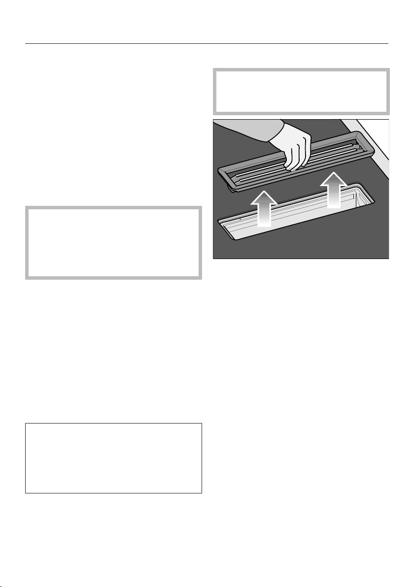
Cleaning and care
61
Cover grille/grease filter/char-
coal filter
The cover grille and the reusable metal
grease filter in the vapour extraction
collect solid matter from kitchen va-
pours (grease, dust, etc.) and therefore
prevent soiling of the countertop ex-
tractor. Accumulated grease solidifies
over a longer period of time and makes
cleaning more difficult. The grease filter
should therefore be cleaned at least
every 3–4weeks.
Risk of fire due to soiled grease
filter.
Grease collected in the grease filter
can ignite.
Clean the grease filter regularly.
Only
KMDA 7473 FR-U, KMDA 7473 FL-U
The charcoal filter reduces odours. It is
used in the vapour extraction in addition
to a grease filter. The charcoal filter in-
cluded with the appliance cannot be
cleaned or reactivated. Replace the
charcoal filter once it has reached the
end of its life. Always read the informa-
tion provided with replacement charcoal
filters.
If liquids (e.g. water or milk) boil over
and come into contact with the char-
coal filter, an odour may develop.
We recommend replacing the charcoal
filter in this case.
Removing the cover grille
Risk of damage to the cover grille.
Pull the cover grille vertically out of
the top of the KMDA.
Take hold of the cover grille in the
centre of the bars.
Pull the cover grille vertically up-
wards.
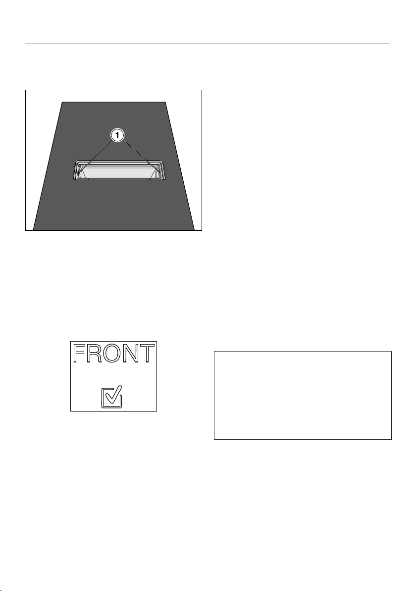
Cleaning and care
62
Cleaning the grease filter
Removing the grease filter
Remove the cover grille.
Carefully remove the grease filter us-
ing the recessed grips (1). Ensure that
you do not tilt the grease filter.
Pour out any liquid which has collec-
ted at the bottom of the grease filter.
Fitting the grease filter
The grease filter has a symbol on the
front.
Insert the grease filter so that the
symbol is pointing towards the front
of the worktop.
Cleaning the grease filter and cover
grille by hand
Clean the cover grille and the grease
filter with a soft nylon brush in a mild
solution of hot water and a little
washing-up liquid. Do not use con-
centrated washing-up liquid.
Cleaning the grease filter and cover
grille in the dishwasher
Place the cover grille upright in the
lower basket.
Place the grease filter with its base
facing upwards in the lower basket.
Ensure the spray arm is not obstruc-
ted.
Use a standard household dish-
washer detergent.
Select a dishwasher programme with
a maximum wash temperature of:
- 55°C for the cover grille
- 65°C for the grease filter
Depending on the detergent used,
cleaning the grease filter in a dish-
washer can cause permanent discol-
ouration to the internal surfaces of the
filter. However, this will not affect the
functioning of the grease filter in any
way.
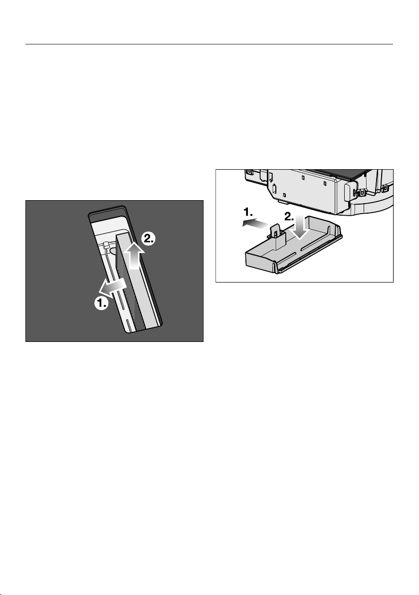
Cleaning and care
63
Replacing the charcoal filter (only
KMDA 7473 FR-U, KMDA 7473 FL-U)
The charcoal filter must be replaced
after 120operating hours. The
sensor control will light up.
The designation of the charcoal filter
can be found in the “Optional accessor-
ies” section.
Remove the cover grille.
Remove the grease filter.
Remove the charcoal filter.
Cleaning the vapour extraction
drip tray
Clean the drip tray if liquid from food
being spilled or boiling over has got into
the vapour extraction unit.
Remove and clean the grease filter as
described in “Cleaning and care –
Grease filter/Cover grille”.
Push the plastic bracket to the left
until the drip tray can be pulled
downwards.
Pour out the liquid.
Clean and dry the drip tray.
Also clean and dry accessible areas
inside of the vapour extraction unit.
Fasten the drip tray back onto the
casing.
Replace the grease filter and refit the
cover grille.

Cleaning and care
64
Cleaning the inside of the fan
unit
Clean the inside of the fan unit if liquid
from food being spilled or boiling over
has got into the vapour extraction unit.
Clean the vapour extraction drip tray.
Place a container under the cleaning
flap to catch the liquid.
Turn the cleaning flap to the left.
Let the liquid run out.
Turn the cleaning flap to the right as
far as it will go.
Internal surfaces of the cooker
hood
Whilst the grease filter is removed re-
move any grease deposits from all
accessible areas of the housing Do-
ing so will prevent a fire hazard.
Resetting the grease filter op-
erating hours counter
After cleaning the grease filter, the oper-
ating hours counter needs to be reset.
Touch the sensor for 3seconds.
The sensor will go out.
Resetting the charcoal filter
operating hours counter (only
KMDA 7473 FR-U, KMDA 7473
FL-U)
Touch the sensor control for
3seconds.
The sensor control will go out.
Problem solving guide
65
Many malfunctions and faults that can occur in daily operation can be easily
remedied. Time and money will be saved because a service call will not be
needed.
The following guide may help you to find the reason for a malfunction or a fault,
and to correct it.
Messages in the display
Problem Cause and remedy
is flashing altern-
ately with in the timer
display and the buzzer
is sounding.
The hob is incorrectly connected.
Disconnect the hob from the mains electricity sup-
ply.
Contact the Customer Service Department. The
hob must be connected to the mains according to
the wiring diagram.
In the cooking zone dis-
play, thesymbol will
flash alternately with
the selected power level
or.
No cookware is present on the cooking zone.
Unsuitable cookware is present on the cooking zone.
Suitable cookware has been removed from the cook-
ing zone.
Use suitable cookware (see “Cookware”).
After the hob has been
switched on, or after
touching a sensor,
appears in the timer
display for a few
seconds.
The system lock or safety lock is activated.
Deactivate the system lock or safety lock (see
“System lock / Safety lock”).
After the hob has been
switched on, appears
briefly in the timer dis-
play. The cooking zones
do not heat up.
The hob is in demonstration mode.
Touch the 0sensor control on any of the numerical
displays.
Then touch the and sensor controls at the
same time until flashes alternately with in
the timer display.
The hob has switched
off automatically. When
the hob is switched
back on, appears
above the On/Off
sensor control.
One or more of the sensor controls are covered, e.g.
by finger contact, food boiling over or an object.
Clean off any dirt and/or remove the object (see
“Safety features – Safety switch-off”).
Problem solving guide
66
Problem Cause and remedy
In the timer display, E-
digit, e.g. E-0, flashes
alternately with , ,
, , , , , or
.
The fan is blocked or defective.
Make sure it has not been blocked by an object.
Remove the obstruction.
If this fault message continues to appear in the
display, contact the Customer Service Depart-
ment.
A message not listed in
this table is appearing
in the timer display.
There is an electronic module fault.
Disconnect the power supply to the hob for ap-
prox. 1minute.
If the problem persists after power has been re-
stored, please contact the Customer Service De-
partment.
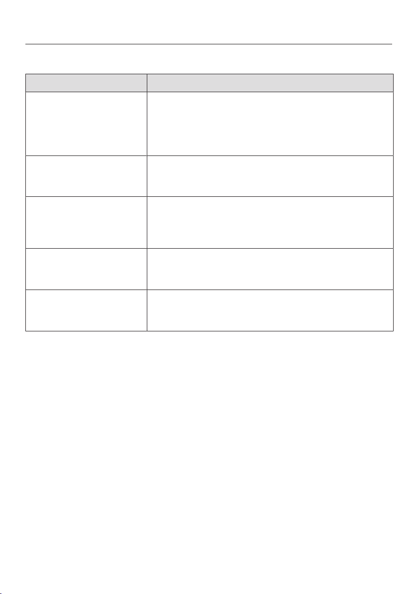
Problem solving guide
67
Unexpected behaviour
Problem Cause and remedy
Power level9 is auto-
matically reduced if you
also set power level9
for the connected cook-
ing zone.
Operating both zones at power level9 exceeds the
permitted maximum power for the two zones.
Use a different cooking zone.
A cooking zone
switches off automatic-
ally.
It has been operated for too long.
You can use the cooking zone again by switching
it back on (see “Safety switch-off”).
The cooking zone is not
working in the usual
way on the power set-
ting selected.
The overheating protection mechanism has been ac-
tivated.
See “Safety features”.
A cooking zone or the
whole hob switches off
automatically.
The overheating protection mechanism has been ac-
tivated.
See “Safety features”.
The Booster has deac-
tivated early automatic-
ally.
The overheating protection mechanism has been ac-
tivated.
See “Safety features”.
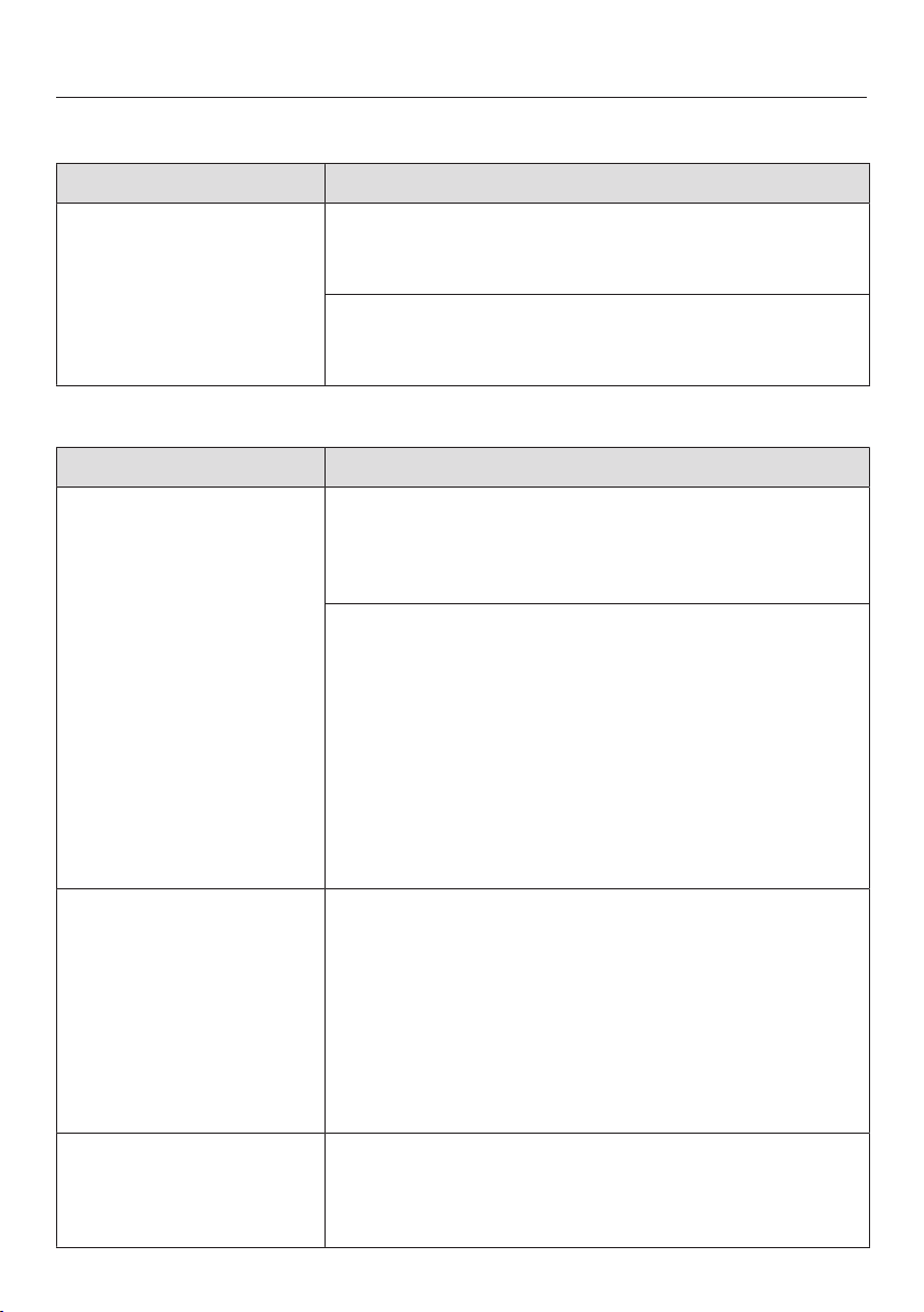
Problem solving guide
68
Unsatisfactory results
Problem Cause and remedy
The food in the pan
does not heat up when
the Auto heat-up func-
tion is switched on.
A large amount of food is being heated up.
Start cooking at the highest power level and then
turn down to a lower one manually later on.
The pan is not conducting heat properly.
Use a different pot or pan which conducts heat
properly.
General problems or technical faults
Problem Cause and remedy
The hob or cooking
zones will not switch
on.
There is no power to the hob.
Check whether the mains fuse has tripped. Con-
tact an electrician or Miele Service (for the min-
imum fuse rating, see data plate).
There may be a technical fault.
Disconnect the appliance from the mains electri-
city supply for approx. 1 minute by
– tripping the relevant mains fuse or screwing the
fuse out completely, or
– switching off at the residual current device.
If, after resetting the trip switch in the mains fuse
box or the residual current current device, the ap-
pliance will still not turn on, contact a qualified
electrician or Miele Service.
A smell and vapours are
given off when the new
appliance is being used.
The metal components have a protective coating.
When the appliance is used for the first time, this
causes a smell and possibly also vapour. The mater-
ial from which the induction coils are made also gives
off a smell in the first few hours of operation. With
each subsequent use, the odour is reduced until it
disappears completely. The smell and any vapours
given off do not indicate a faulty connection or appli-
ance and they are not hazardous to health.
An operating noise can
be heard after the appli-
ance has been switched
off.
The cooling fan runs until the hob has cooled down
and then switches off automatically.
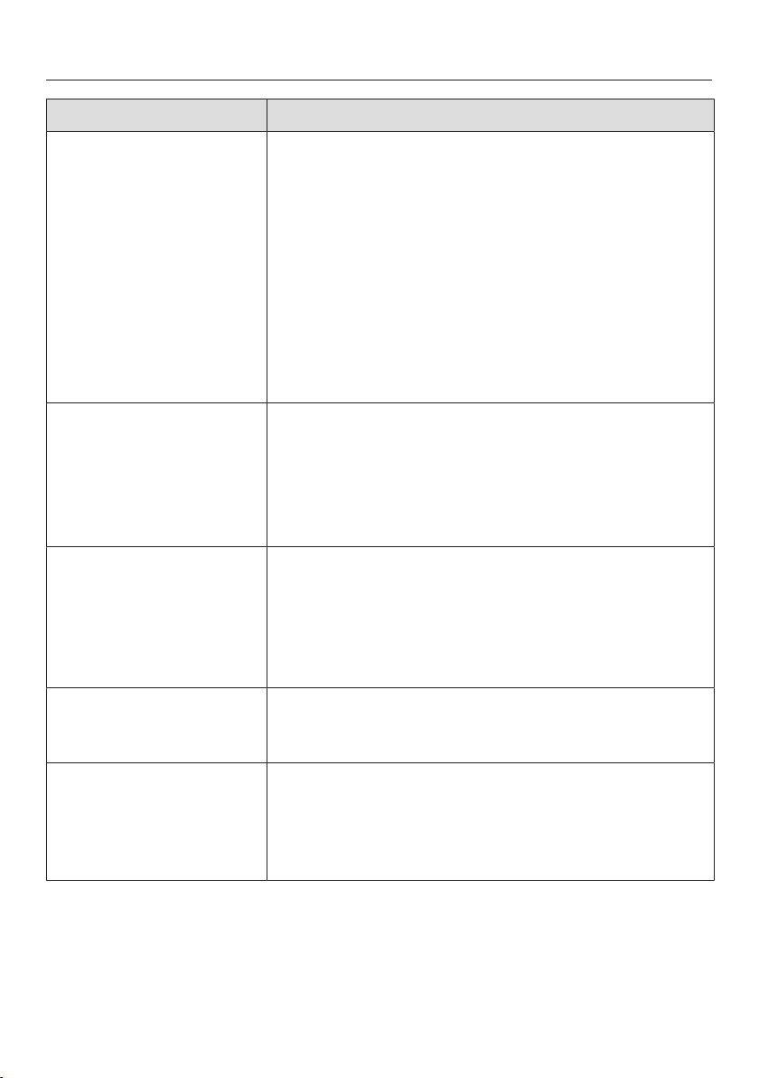
Problem solving guide
69
Problem Cause and remedy
Liquid has got into the
vapour extraction.
Due to boiling over or spillage, liquid has made its
way through the cover grille into the vapour extrac-
tion.
The base of the grease filter and the drip tray can
hold approx. 800ml of liquid in total.
Switch the vapour extraction off.
Clean the grease filter, the drip tray, the inside of
the casing and the fan motor compartment (see
“Cleaning and care”).
KMDA 7473 FR-U, KMDA 7473 FL-U only: replace
the charcoal filter (see “Cleaning and care – Repla-
cing the charcoal filter”).
Extraction power has
decreased. Extraction
noise has increased.
Objects (e.g. a cloth) have been drawn into the va-
pour extraction.
Switch the vapour extraction off.
Remove the grease filter (see “Cleaning and care –
Cleaning the grease filter”).
Remove any objects from the grease filter.
The sensor control is
lit up.
The charcoal filter must be replaced.
Replace the charcoal filter (see “Cleaning and care
– Replacing the charcoal filter”).
Reset the operating hours counter (see “Cleaning
and care – Resetting the charcoal filter operating
hours counter”).
The sensor control is
lit up.
The grease filter must be cleaned.
Clean the grease filter as described in “Cleaning
and care – Cleaning the grease filter”.
The sensor control
does not light up.
The Con@ctivity function of the integrated vapour ex-
traction is permanently deactivated.
Activate the Con@ctivity function of the integrated
vapour extraction in the programming (see “Pro-
gramming”).

Optional accessories
70
Miele offer a comprehensive range of
useful accessories as well as cleaning
and conditioning products for your
Miele appliances.
These products can be ordered through
the Miele Webshop.
They can also be ordered from Miele
(see end of this booklet for contact de-
tails) or from your Miele dealer.
Cookware
Miele offers a wide range of cookware.
These have all been optimised for Miele
appliances in terms of functionality and
dimensions. Detailed information is
provided on the Miele website.
Charcoal filter
Only the Miele charcoal filters listed
here are suitable for the KMDA variants
covered by these operating instructions:
- DKF 35-P
- DKF 35-S
Further accessories for vapour
extraction
Further accessories, e.g. for air guid-
ance, can be ordered from the Miele
online shop. Detailed information is
provided on the Miele website.
Cleaning and care products
Ceramic and stainless steel hob
cleaner 250ml
Removes heavy soiling, limescale de-
posits and aluminium residues.
Microfibre cloth
For removing finger marks and light
soiling.
Installation
*INSTALLATION*
71
Safety instructions for installation
Risk of damage from incorrect connection.
Incorrect installation can cause damage to the hob.
The hob must only be installed by a qualified person.
Risk of electric shock from mains voltage.
Incorrect connection to the mains supply may result in an electric shock.
The hob must be connected to the electrical supply by a qualified electrician
only.
Damage from falling objects.
Take care not to damage the hob when fitting wall units or a cooker hood above
it.
Fit the wall units and the cooker hood before the hob.
The veneer or laminate coatings of worktops (or adjacent kitchen
units) must be treated with 100°C heat-resistant adhesive which will
not dissolve or distort. Any backmoulds must be of heat-resistant
material.
The hob must not be installed over a fridge, fridge-freezer, freezer,
dishwasher, washing machine, washer-dryer or tumble dryer.
A gas hob must not be installed next to this hob.
This hob must not be installed above ovens or cookers unless
these have a built-in cooling down fan.
After installation, ensure that nothing can come into contact with
the connection cable and that it is without hindrance.
The electrical cable may not come into contact with any moving
kitchen component (e.g. a drawer) or be subject to mechanical ob-
struction which could damage it.
Observe carefully the safety clearances listed on the following
pages.

Installation
*INSTALLATION*
72
Exhaust ducting must be of non-inflammable material. Suitable
material is available from Miele specialist dealers or the Miele Spares
Dept.
The appliance must not be connected to a chimney or flue which
is in use. Neither should it be connected to ducting which ventilates
rooms with fireplaces.
If exhaust air is to be extracted into a chimney or ventilation duct
no longer used for other purposes, seek professional advice.
The exhaust air drawn into the vapour extraction may only be
routed through the base unit and back into the room in Plug&Play
mode. In extraction mode and in guided recirculation mode, the ex-
haust air must be routed outside through ducting (extraction mode)
or back into the room through the recirculation box (guided recircula-
tion mode).
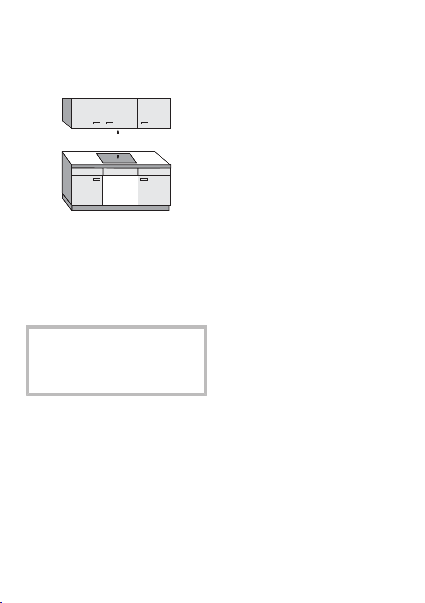
Installation
*INSTALLATION*
73
Safety distances
Safety distance above the hob
The safety distance specified by the
manufacturer of the cooker hood must
be maintained between the hob and the
cooker hood above it.
If combustible objects are installed
above the hob (e.g., cabinets, utensil
rail, etc.), a minimum safety distance of
500mm must be maintained.
When two or more appliances which
have different safety distances are
installed together below a cooker
hood, you should observe the
greatest specified safety distance.
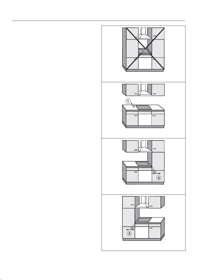
Installation
*INSTALLATION*
74
Safety distances to the sides and
back of the appliance
It is advisable to install the hob with
plenty of space either side of it.
The minimum distance shown below
must be maintained between the back
of the hob and a tall unit or wall.
The minimum distance , shown
below must be maintained between a
tall unit or a wall to the left or right of
the hob with a minimum distance of
300mm on the opposite side.
Minimum distance between the back
of the worktop cut-out and the rear
edge of the worktop:
50mm
Minimum distance between the
worktop cut-out and a wall or tall unit to
the right of it:
50mm.
Minimum distance between the
worktop cut-out and a wall or tall unit to
the left of it:
50mm.
Not allowed
Highly recommended
Not recommended
Not recommended
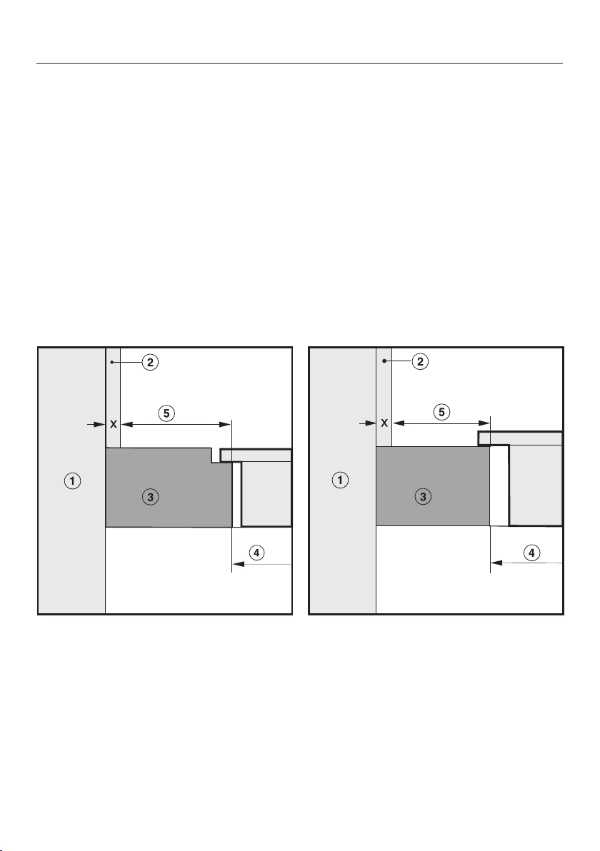
Installation
*INSTALLATION*
75
Safety distance to niche cladding
If niche cladding is installed, a minimum safety distance must be maintained
between the worktop cut-out and the cladding, since high temperatures can alter
or damage these materials.
If the niche cladding is made from a combustible material (e.g. wood), a minimum
safety distance of 50mm must be maintained between the worktop cut-out and
the cladding.
If the niche cladding is made from a non-combustible material (e.g. metal, natural
stone, ceramic tiles), the minimum safety distance between the worktop cut-out
and the cladding will be 50mm minus the thickness of the cladding.
Example: 15mm thick niche cladding
50mm – 15mm = minimum safety distance of 35mm
Flush-fit installation Surface-mounted installation
aMasonry
bNiche cladding dimensionx= thickness of the niche cladding material
cWorktop
dWorktop cut-out
eMinimum safety distance to
combustible materials 50mm
non-combustible materials 50mm – dimension x
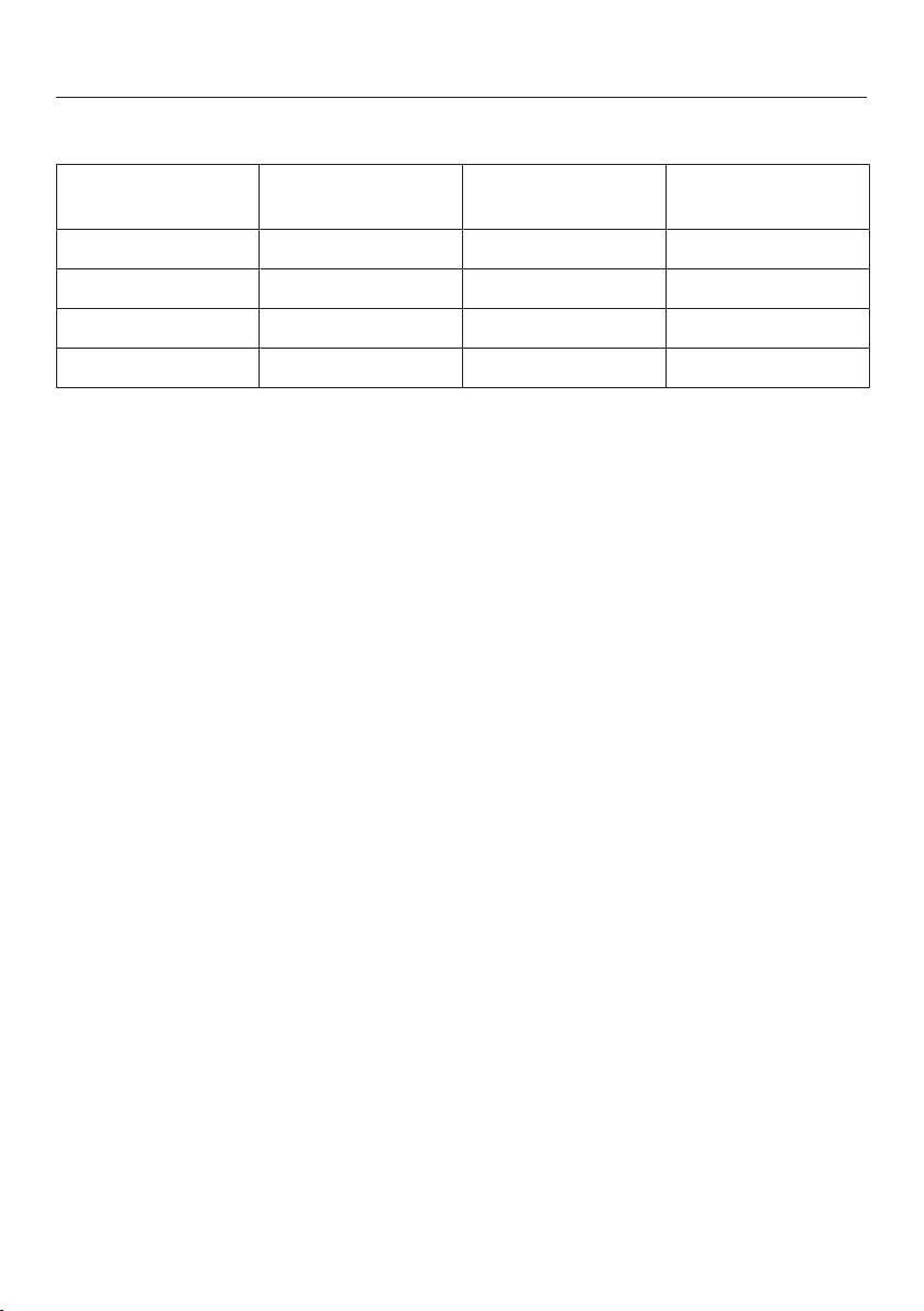
Installation
*INSTALLATION*
76
Operating options
Extraction mode Guided
recirculation mode
Plug&Play mode
KMDA 7473 FR-A – –
KMDA 7473 FR-U –
KMDA 7473 FL-A – –
KMDA 7473 FL-U –
Possible
Possible – additional accessories required
– Not possible
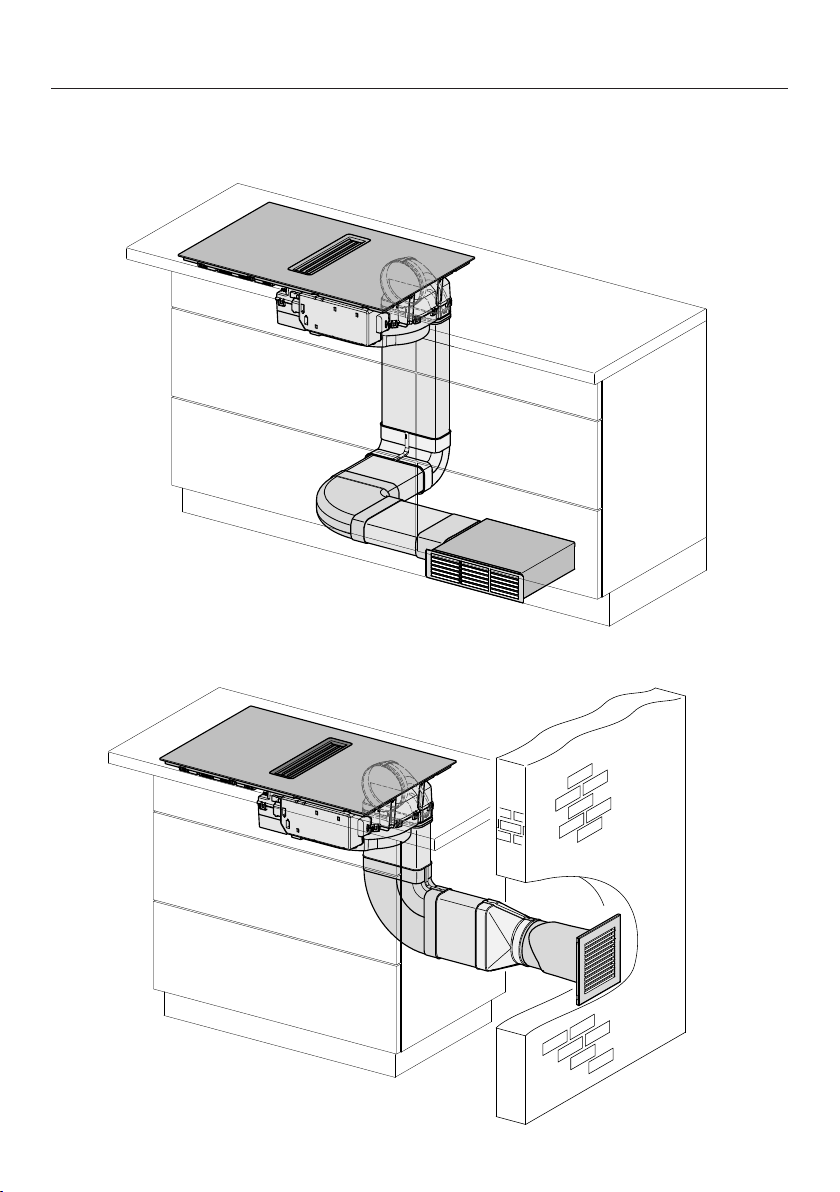
Installation
*INSTALLATION*
77
Installation examples
Guided recirculation mode
Extraction mode
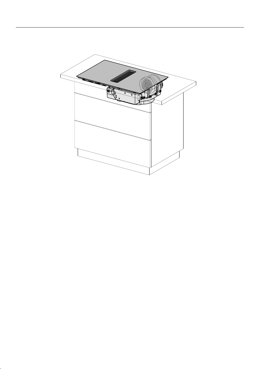
Installation
*INSTALLATION*
78
Plug&Play mode
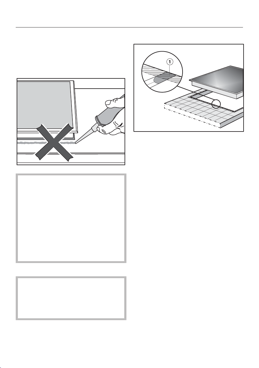
Installation
*INSTALLATION*
79
Installation notes –
surface-mounted
Seal between the hob and the work-
top
Damage caused by incorrect in-
stallation.
Using sealant under the hob could
result in damage to the hob and the
worktop if the hob ever needs to be
removed for servicing.
Do not use sealant between the hob
and the worktop.
The sealing strip under the edge of
the hob provides a sufficient seal for
the worktop.
Sealing strip
Dismantling the hob for service pur-
poses may damage the sealing strip
underneath the edge of the hob.
Always replace the sealing strip be-
fore reinstalling the hob.
Tiled worktops
Grout lines and the hatched area un-
derneath the hob frame must be
smooth and even. If they are not the
hob will not sit flush with the worktop
and the sealing strip underneath the
hob will not provide a good seal
between the hob and the worktop.
Installation
*INSTALLATION*
80
Minimum plinth height
The minimum plinth height of the
KMDA 7473 FR-U, KMDA 7473 FL-U is:
- Guided recirculation mode: 100mm
- Plug&Play mode: 25mm
Cross-section of the ventilation
opening –
Plug&Play mode
The cross-section of the ventilation
opening must be at least 425cm².
If ventilation grilles are to be inserted
into the ventilation gaps, the ventila-
tion gaps must be larger than
425cm². The unobstructed airflow of
425cm² is calculated by adding up
the total area of ventilation openings
in the grilles.
The ventilation gaps must not be
covered or blocked in any way. They
must also be regularly dusted.
Housing unit back panel
The extraction ducting is laid behind the
housing unit back panel. The back
panel must be removable for mainten-
ance purposes.
Grease trap and cleaning flap
The hob must be installed such that the
grease trap and the cleaning flap are
easily accessible and can be removed
for cleaning.
Drilling template
The template supplied with the hob is
required for installation.
Plug&Play adapter
The Plug&Play adapter supplied with
the hob is required for operation in
Plug&Play mode.
Removing the transverse struts –
Plug&Play mode
The crossbeams in front of the top area
of the housing unit back panel must be
removed in order to install the
Plug&Play adapter.
Installation
*INSTALLATION*
81
U value
Plug&Play operation is possible in younger or renovated buildings. If the adjacent
wall or the floor is in contact with the ground or the outside air, it must have a heat
transfer coefficient (U value) of ≤ 0.5W/(m²K).
Material Material thickness U value(as of 1995)
Solid wall
(vertical coring brick, floating brick or com-
parable porous or highly perforated materi-
als)
≥ 30cm 0.5
Solid timber wall
(e.g. log cabin/prefabricated house). Timber
frame or timber panel wall with insulating
filling
– 0.4
Passive house
(KfW 55, 40, 40 Plus)
– 0.15–0.2
The U values for other materials can be found on the websites of the German Fed-
eral Ministry for Economic Affairs and Climate Action and the German Federal Min-
istry of the Interior and Community.
If you have any other questions about your building, please contact a construction
expert or energy adviser.
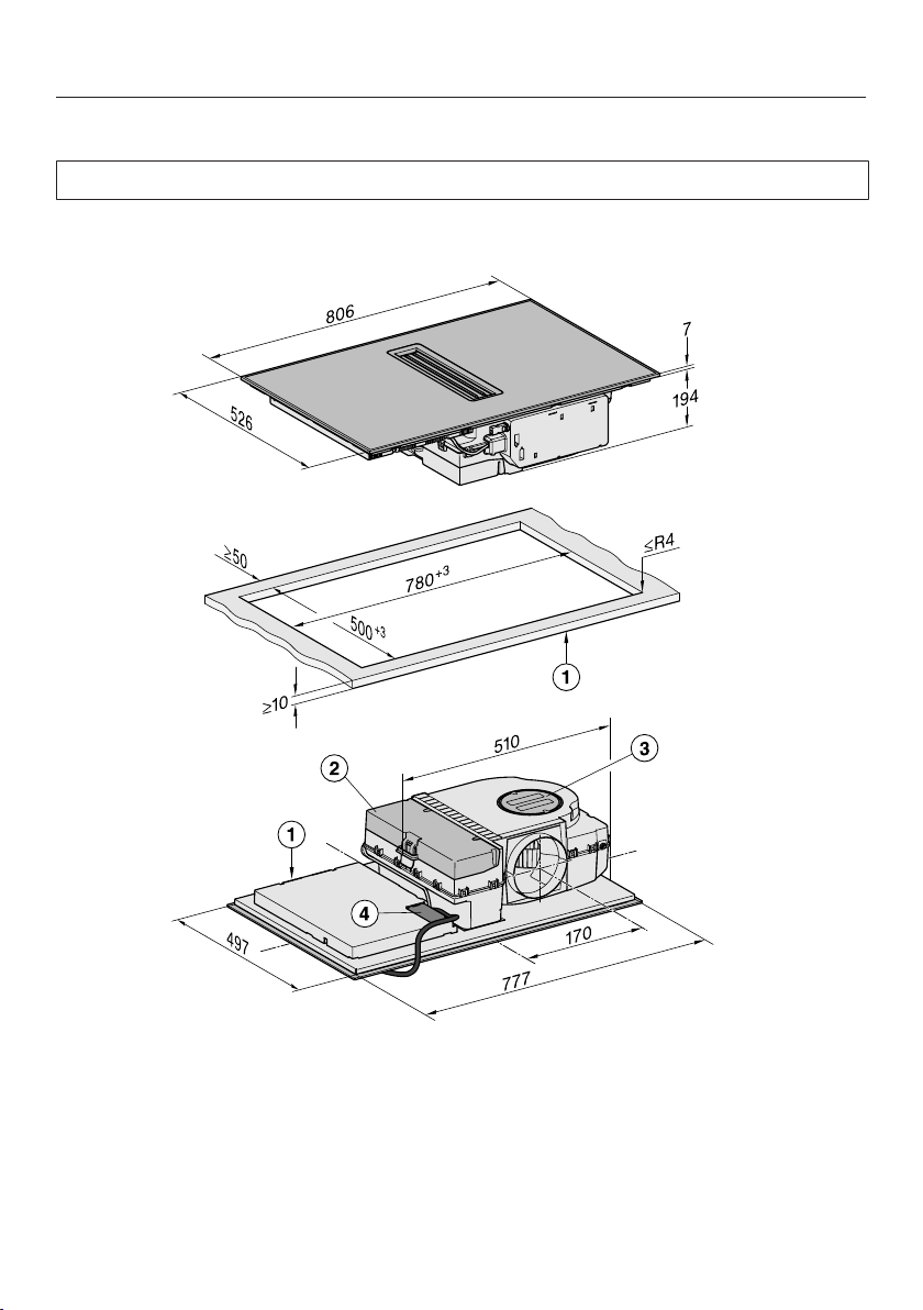
Installation
*INSTALLATION*
82
Installation dimensions–Surface-mounted
All dimensions are given in mm.
KMDA 7473 FR-A, KMDA 7473 FR-U
aFront
bRemovable drip tray
cCleaning flap
dMains connection box with mains connection cable
Mains connection cable L=1440mm
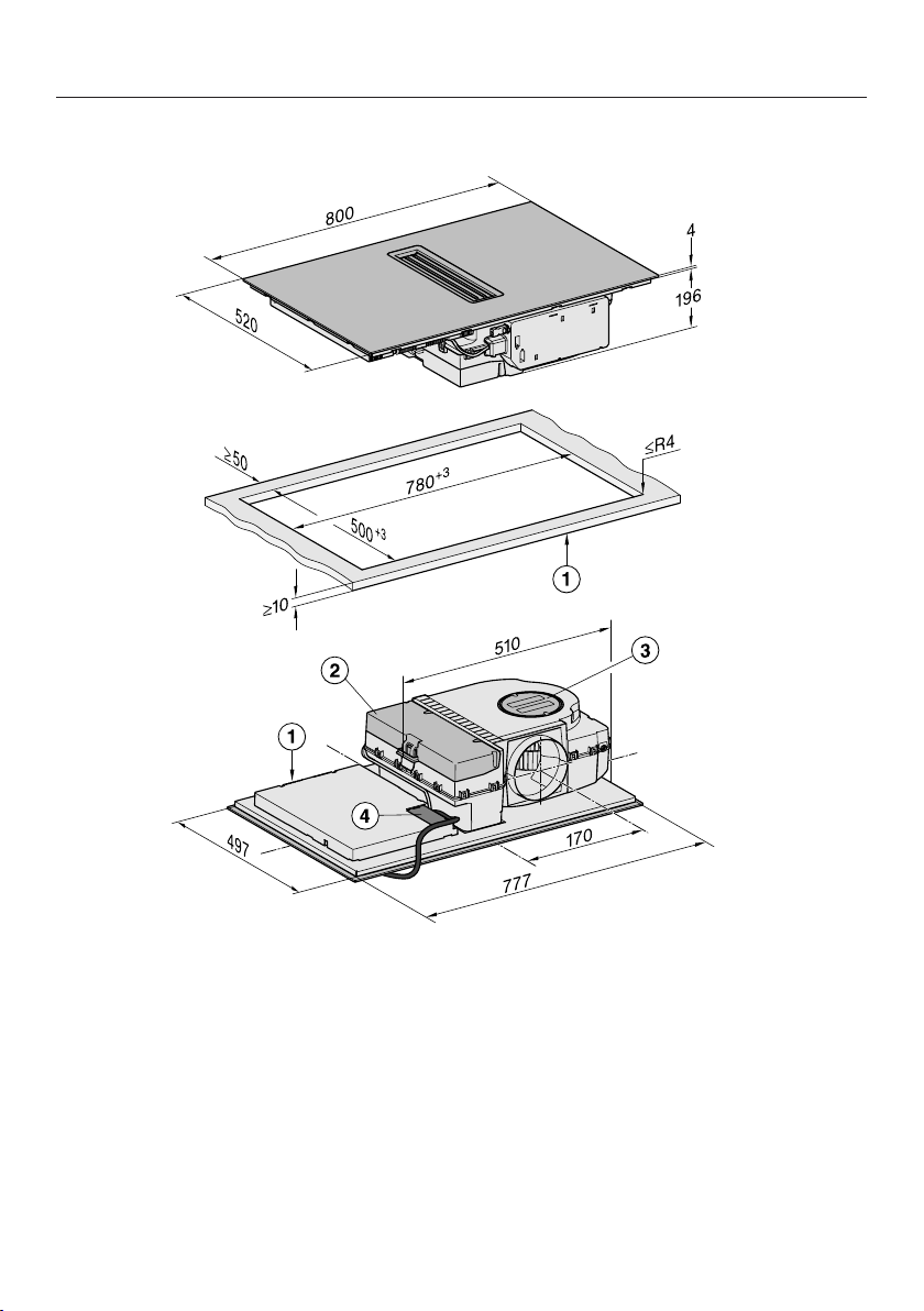
Installation
*INSTALLATION*
83
KMDA 7473 FL-A, KMDA 7473 FL-U
aFront
bRemovable drip tray
cCleaning flap
dMains connection box with mains connection cable
Mains connection cable L=1440mm
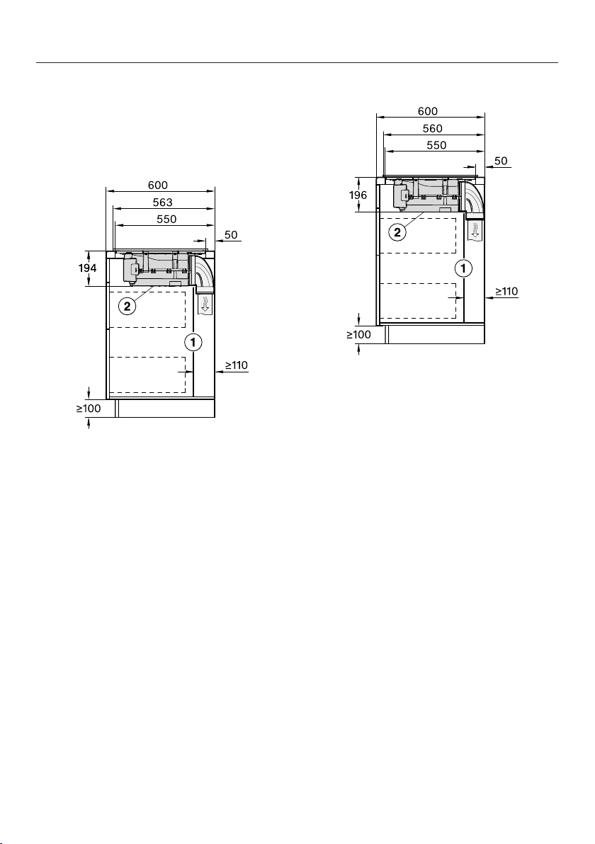
Installation
*INSTALLATION*
84
Extraction and guided recirculation
mode
Worktop depth 600mm
KMDA 7473 FR-A, KMDA 7473 FR-U
aFor maintenance work it must be
possible to remove the rear cabinet
wall.
The cabinet wall and an adjoining
room wall or a piece of furniture
must be at least 110mm apart to
ensure sufficient room for the duct-
ing.
bThe removable drip tray and the
cleaning flap must be accessible
after installation.
KMDA 7473 FL-A, KMDA 7473 FL-U
aFor maintenance work it must be
possible to remove the rear cabinet
wall.
The cabinet wall and an adjoining
room wall or a piece of furniture
must be at least 110mm apart to
ensure sufficient room for the duct-
ing.
bThe removable drip tray and the
cleaning flap must be accessible
after installation.
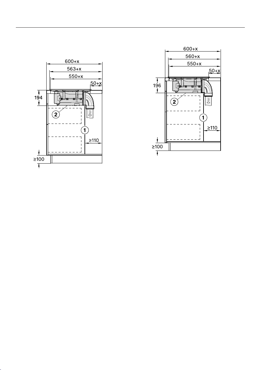
Installation
*INSTALLATION*
85
Worktop depth greater than 600mm
KMDA 7473 FR-A, KMDA 7473 FR-U
aFor maintenance work it must be
possible to remove the rear cabinet
wall.
The cabinet wall and an adjoining
room wall or a piece of furniture
must be at least 110mm apart to
ensure sufficient room for the duct-
ing.
bThe removable drip tray and the
cleaning flap must be accessible
after installation.
x Dimension of which the worktop is
deeper than 600mm.
KMDA 7473 FL-A, KMDA 7473 FL-U
aFor maintenance work it must be
possible to remove the rear cabinet
wall.
The cabinet wall and an adjoining
room wall or a piece of furniture
must be at least 110mm apart to
ensure sufficient room for the duct-
ing.
bThe removable drip tray and the
cleaning flap must be accessible
after installation.
x Dimension of which the worktop is
deeper than 600mm.
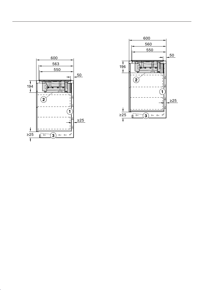
Installation
*INSTALLATION*
86
Plug&Play mode
Worktop depth 600mm
KMDA 7473 FR-U
aFor maintenance work it must be
possible to remove the rear cabinet
wall.
The cabinet wall and an adjoining
room wall or a piece of furniture
must be at least 25mm apart to en-
sure sufficient room for the ducting.
bThe removable drip tray and the
cleaning flap must be accessible
after installation.
cThe cross-section of the ventilation
opening must be at least 425cm².
KMDA 7473 FL-U
aFor maintenance work it must be
possible to remove the rear cabinet
wall.
The cabinet wall and an adjoining
room wall or a piece of furniture
must be at least 25mm apart to en-
sure sufficient room for the ducting.
bThe removable drip tray and the
cleaning flap must be accessible
after installation.
cThe cross-section of the ventilation
opening must be at least 425cm².
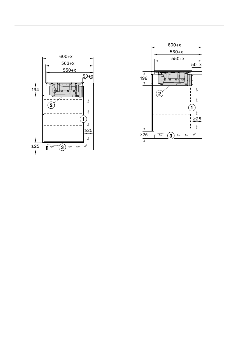
Installation
*INSTALLATION*
87
Worktop depth greater than 600mm
KMDA 7473 FR-U
aFor maintenance work it must be
possible to remove the rear cabinet
wall.
The cabinet wall and an adjoining
room wall or a piece of furniture
must be at least 25mm apart to en-
sure sufficient room for the ducting.
If the rear cabinet wall is >555mm
away from the front of the worktop,
the Plug&Play adapter must be com-
bined with an expansion set from
Miele.
bThe removable drip tray and the
cleaning flap must be accessible
after installation.
cThe cross-section of the ventilation
opening must be at least 425cm².
x Dimension of which the worktop is
deeper than 600mm.
KMDA 7473 FL-U
aFor maintenance work it must be
possible to remove the rear cabinet
wall.
The cabinet wall and an adjoining
room wall or a piece of furniture
must be at least 25mm apart to en-
sure sufficient room for the ducting.
If the rear cabinet wall is >555mm
away from the front of the worktop,
the Plug&Play adapter must be com-
bined with an expansion set from
Miele.
bThe removable drip tray and the
cleaning flap must be accessible
after installation.
cThe cross-section of the ventilation
opening must be at least 425cm².
x Dimension of which the worktop is
deeper than 600mm.

Installation
*INSTALLATION*
88
Connection to window contact,
if required
The window contact connection
is live!
Danger of electric shock!
Disconnect the hob from the mains
electricity supply before connecting
the switching mechanism.
The connection cable for the switch-
ing system must only be connected
by a suitably qualified electrician.
The connection cable for the switch-
ing system must comply with type
H03VV-F 2x0.75mm2 and must not
exceed 2.0m in length.
The switching system must be
equipped with a potential-free con-
tact suitable for 230V, 1A. The va-
pour extraction is switched off when
the switch is open.
Only use DIBt-approved and tested
radio switching systems (e.g. window
contact switches, pressure switches)
and have them approved by author-
ised specialists (e.g. building regula-
tions inspector).
You will need the appropriate ex-
ternal switching system documents
to safely connect and operate the
switch.
Loosen the lug and pull the plug out.
Loosen the strain relief screws and
unlock the casing on both sides.
Open the casing.
Remove the stopper.
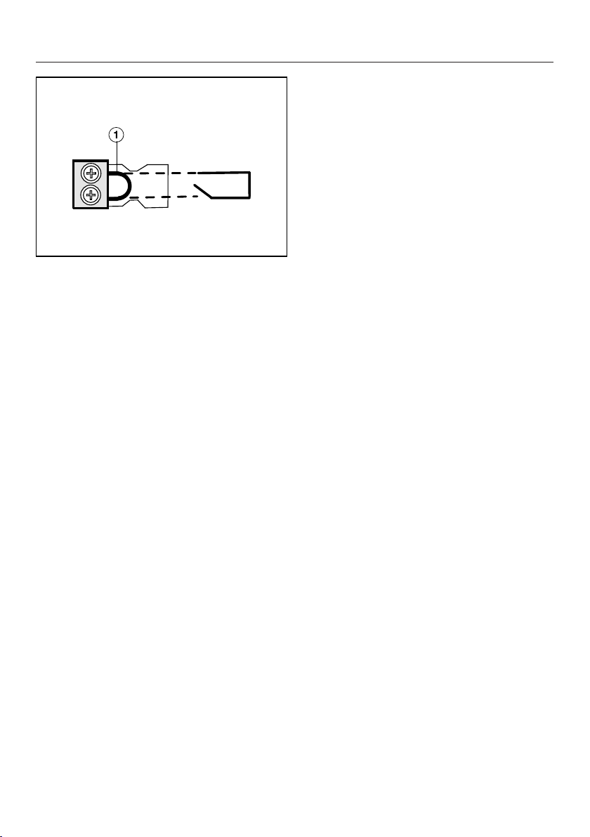
Installation
*INSTALLATION*
89
Exchange the bridge for the con-
nection cable of the switching sys-
tem.
Close the casing.
Tighten the strain relief screw.
Reinsert the plug.
Installation
*INSTALLATION*
90
Surface-mounted installation
Create the worktop cut-out. Remem-
ber to maintain the minimum safety
distances (see “Installation – Safety
distances”).
Cut the top of the drilling template to
the thickness of your worktop. Place
it on the cabinet rear wall with side2
facing up. Use the drilling template to
create a cut-out for the air duct or the
Plug&Play adapter.
If you do not have a drilling template,
see “Installation – Rear wall cut-out –
without drilling template”.
Seal any cut surfaces on wooden
worktops with a special varnish, sil-
icone sealant or resin to prevent the
wood from swelling as a result of
moisture ingress. The sealant must
be heat-resistant.
Make sure that the sealant does not
come into contact with the top of the
worktop.
Stick the sealing strip supplied under
the edge of the hob. Do not apply the
sealing strip under tension.
The Plug&Play adapter may break
off.
When placing the hob on the work-
top, make sure that it is not placed
on top of the Plug&Play adapter.
Feed the mains connection cable for
the hob down through the worktop
cut-out.
Plug&Play mode: remove the protect-
ive foil from the adhesive tape at the
end of the Plug&Play adapter.
Place the hob centrally in the cut-out.
When doing this, make sure that the
seal of the appliance sits flush with
the worktop on all sides. This is im-
portant to ensure an effective seal all
round.
Do not use any additional sealant
(e.g. silicone) on the hob.
If the seal does not sit flush with the
worktop in the corners, the corner ra-
dius (≤R4) can be carefully cut to fit
using a jigsaw.
Plug&Play mode: align the Plug&Play
adapter with the predrilled hole. Press
the adapter onto the rear wall until it
sticks in place.
Connect the hob to the power supply.
Check that the hob works.
Installation
*INSTALLATION*
91
Installation notes –
flush-fit
A flush-fit hob is suitable only for in-
stallation in natural stone (granite,
marble), solid wood and tiled work-
tops. Certain models are also suitable
for building into glass worktops –
these are marked with an appropriate
note in “Installation – Installation di-
mensions – flush-fit”. When using a
worktop made from any other mater-
ial, please check first with the worktop
manufacturer that it is suitable for in-
stalling a flush-fit hob.
The internal width of the base unit un-
derneath the appliance must be at
least as wide as the inner worktop cut-
out (see “Installation – Installation di-
mensions – flush fit”), so that the hob
is easily accessible from underneath
after installation and the casing can be
removed for maintenance. If the un-
derside of the hob is not freely ac-
cessible after installation, any sealant
used must be removed to enable the
hob to be lifted out of the cut-out
should this be necessary.
Natural stone worktops
The hob is set directly in the cut-out.
Solid wood worktops, tiled worktops,
glass worktops
The hob is secured inside the cut-out
with wooden battens. The battens must
be provided on site, and are not sup-
plied with the appliance.
Sealing strip
Dismantling the hob for service pur-
poses may damage the sealing strip
underneath the edge of the hob.
Always replace the sealing strip be-
fore reinstalling the hob.

Installation
*INSTALLATION*
92
Minimum plinth height
The minimum plinth height of the
KMDA 7473 FR-U, KMDA 7473 FL-U is:
- Guided recirculation mode: 100mm
- Plug&Play mode: 25mm
Cross-section of the ventilation
opening –
Plug&Play mode
The cross-section of the ventilation
opening must be at least 425cm².
If ventilation grilles are to be inserted
into the ventilation gaps, the ventila-
tion gaps must be larger than
425cm². The unobstructed airflow of
425cm² is calculated by adding up
the total area of ventilation openings
in the grilles.
The ventilation gaps must not be
covered or blocked in any way. They
must also be regularly dusted.
Housing unit back panel
The extraction ducting is laid behind the
housing unit back panel. The back
panel must be removable for mainten-
ance purposes.
Grease trap and cleaning flap
The hob must be installed such that the
grease trap and the cleaning flap are
easily accessible and can be removed
for cleaning.
Drilling template
The template supplied with the hob is
required for installation.
Plug&Play adapter
The Plug&Play adapter supplied with
the hob is required for operation in
Plug&Play mode.
Removing the transverse struts –
Plug&Play mode
The crossbeams in front of the top area
of the housing unit back panel must be
removed in order to install the
Plug&Play adapter.

Installation
*INSTALLATION*
93
U value
Plug&Play operation is possible in younger or renovated buildings. If the adjacent
wall or the floor is in contact with the ground or the outside air, it must have a heat
transfer coefficient (U value) of ≤ 0.5W/(m²K).
Material Material thickness U value(as of 1995)
Solid wall
(vertical coring brick, floating brick or com-
parable porous or highly perforated materi-
als)
≥ 30cm 0.5
Solid timber wall
(e.g. log cabin/prefabricated house). Timber
frame or timber panel wall with insulating
filling
– 0.4
Passive house
(KfW 55, 40, 40 Plus)
– 0.15–0.2
The U values for other materials can be found on the websites of the German Fed-
eral Ministry for Economic Affairs and Climate Action and the German Federal Min-
istry of the Interior and Community.
If you have any other questions about your building, please contact a construction
expert or energy adviser.
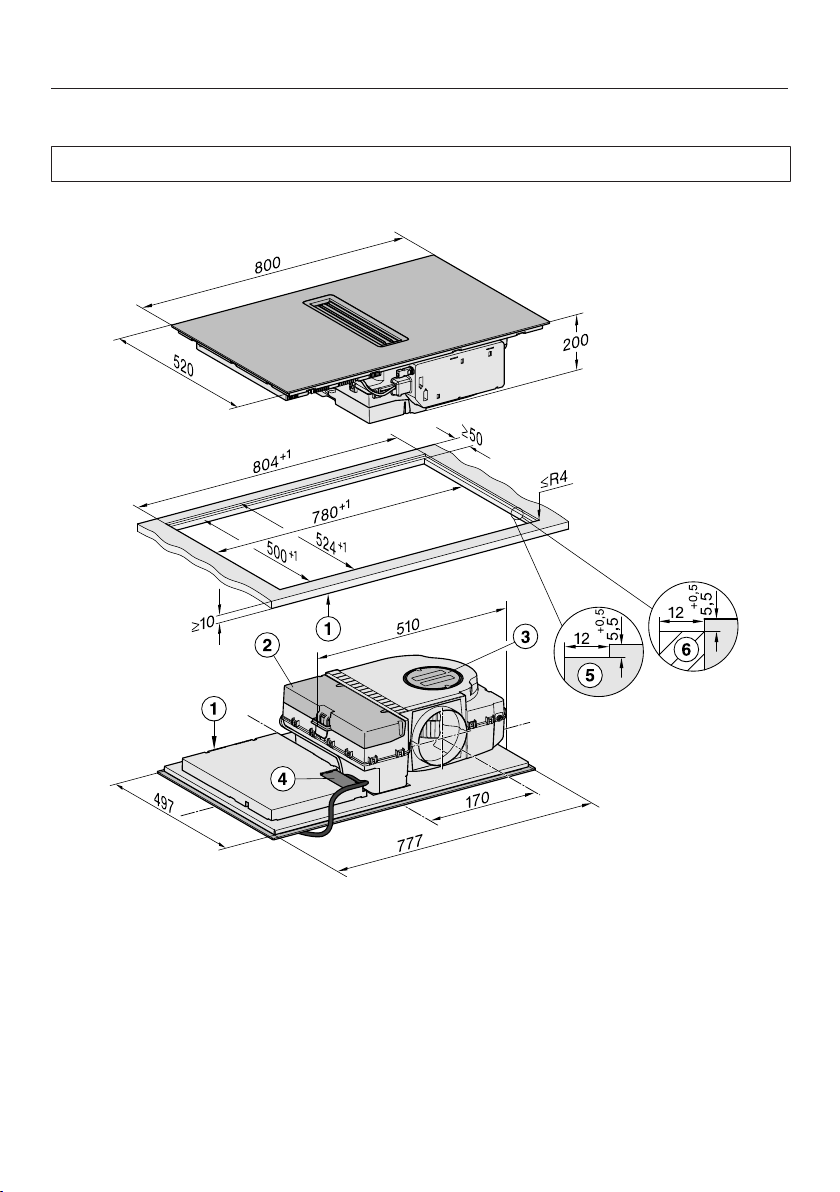
Installation
*INSTALLATION*
94
Installation dimensions–Flush-fit
All dimensions are given in mm.
KMDA 7473 FL-A, KMDA 7473 FL-U
aFront
bRemovable drip tray
cCleaning flap
dMains connection box with mains connection cable
Mains connection cable L=1440mm
eStepped cut-out, natural stone worktop
fWooden batten 12mm (not supplied)
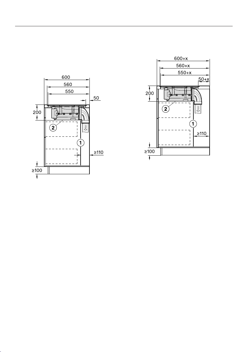
Installation
*INSTALLATION*
95
Extraction and guided recirculation
mode
Worktop depth 600mm
KMDA 7473 FL-A, KMDA 7473 FL-U
aFor maintenance work it must be
possible to remove the rear cabinet
wall.
The cabinet wall and an adjoining
room wall or a piece of furniture
must be at least 110mm apart to
ensure sufficient room for the duct-
ing.
bThe removable drip tray and the
cleaning flap must be accessible
after installation.
Worktop depth greater than 600mm
KMDA 7473 FL-A, KMDA 7473 FL-U
aFor maintenance work it must be
possible to remove the rear cabinet
wall.
The cabinet wall and an adjoining
room wall or a piece of furniture
must be at least 110mm apart to
ensure sufficient room for the duct-
ing.
bThe removable drip tray and the
cleaning flap must be accessible
after installation.
x Dimension of which the worktop is
deeper than 600mm.
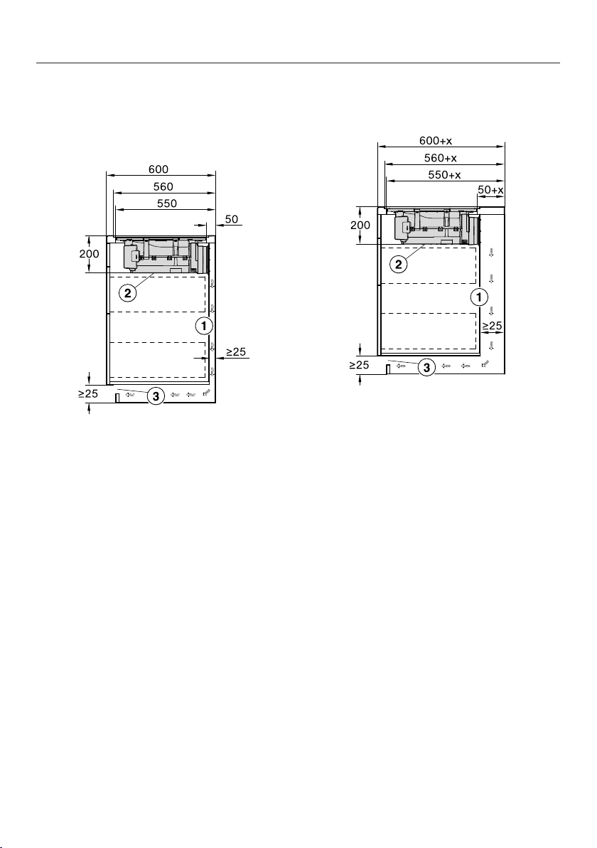
Installation
*INSTALLATION*
96
Plug&Play mode
Worktop depth 600mm
KMDA 7473 FL-U
aFor maintenance work it must be
possible to remove the rear cabinet
wall.
The cabinet wall and an adjoining
room wall or a piece of furniture
must be at least 25mm apart to en-
sure sufficient room for the ducting.
bThe removable drip tray and the
cleaning flap must be accessible
after installation.
cThe cross-section of the ventilation
opening must be at least 425cm².
Worktop depth greater than 600mm
KMDA 7473 FL-U
aFor maintenance work it must be
possible to remove the rear cabinet
wall.
The cabinet wall and an adjoining
room wall or a piece of furniture
must be at least 25mm apart to en-
sure sufficient room for the ducting.
If the rear cabinet wall is >555mm
away from the front of the worktop,
the Plug&Play adapter must be com-
bined with an expansion set from
Miele.
bThe removable drip tray and the
cleaning flap must be accessible
after installation.
cThe cross-section of the ventilation
opening must be at least 425cm².
x Dimension of which the worktop is
deeper than 600mm.
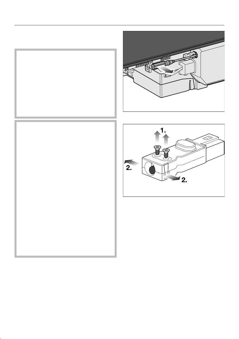
Installation
*INSTALLATION*
97
Connection to window contact,
if required
The window contact connection
is live!
Danger of electric shock!
Disconnect the hob from the mains
electricity supply before connecting
the switching mechanism.
The connection cable for the switch-
ing system must only be connected
by a suitably qualified electrician.
The connection cable for the switch-
ing system must comply with type
H03VV-F 2x0.75mm2 and must not
exceed 2.0m in length.
The switching system must be
equipped with a potential-free con-
tact suitable for 230V, 1A. The va-
pour extraction is switched off when
the switch is open.
Only use DIBt-approved and tested
radio switching systems (e.g. window
contact switches, pressure switches)
and have them approved by author-
ised specialists (e.g. building regula-
tions inspector).
You will need the appropriate ex-
ternal switching system documents
to safely connect and operate the
switch.
Loosen the lug and pull the plug out.
Loosen the strain relief screws and
unlock the casing on both sides.
Open the casing.
Remove the stopper.

Installation
*INSTALLATION*
98
Exchange the bridge for the con-
nection cable of the switching sys-
tem.
Close the casing.
Tighten the strain relief screw.
Reinsert the plug.
Installation
*INSTALLATION*
99
Flush-fit installation
Create the worktop cut-out. Remem-
ber to maintain the minimum safety
distances (see “Installation – Safety
distances”).
Cut the top of the drilling template to
the thickness of your worktop. Place
it on the cabinet rear wall with side1
facing up. Use the drilling template to
create a cut-out for the air duct or the
Plug&Play adapter.
If you do not have a drilling template,
see “Installation – Rear wall cut-out –
without drilling template”.
Solid wood, tiled and glass worktops:
Fix a wooden frame 5,5mm below
the top edge of the worktop (see “In-
stallation dimensions – flush-fit”).
Stick the sealing strip supplied under
the edge of the hob. Do not apply the
sealing strip under tension.
The Plug&Play adapter may break
off.
When placing the hob on the work-
top, make sure that it is not placed
on top of the Plug&Play adapter.
Feed the mains connection cable for
the hob down through the worktop
cut-out.
Plug&Play mode: remove the protect-
ive foil from the adhesive tape at the
end of the Plug&Play adapter.
Centre the hob in the cut-out.
The gap between the ceramic glass
surface and the worktop must be at
least 2mm wide. This is required so
that the hob can be sealed.
Plug&Play mode: align the Plug&Play
adapter with the predrilled hole. Press
the adapter onto the rear wall until it
sticks in place.
Connect the hob to the power supply.
Check that the hob works.
Seal the gap between the hob and
worktop with a silicone sealant that is
heat-resistant to at least 160°C.
Damage from unsuitable sealant.
Unsuitable sealant can damage nat-
ural stone.
For natural stone worktops and nat-
ural stone tiles, only use silicone
sealant that is specially formulated
for natural stone. Follow the manu-
facturer’s instructions.
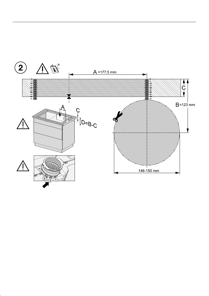
Installation
*INSTALLATION*
100
Rear wall cut-out – without drilling template
Ideally, the drilling template supplied with the appliance should be used. The fol-
lowing instructions should only be used if the drilling template is not available.
Surface-mounted installation
View of the drilling template side 2. Not to scale.
Measure the thickness of your worktop (C).
Determine the midpoint of the longest side of the cut-out.
Mark the point that is 177.5mm (A) to the right of the midpoint.
Mark the point (D) that is (123mm – C (thickness of the worktop)) below the right
end of distance A.
Saw a hole with a diameter of 146–150mm around this point.
Plug&Play mode only: engage the Plug&Play adapter in position2.
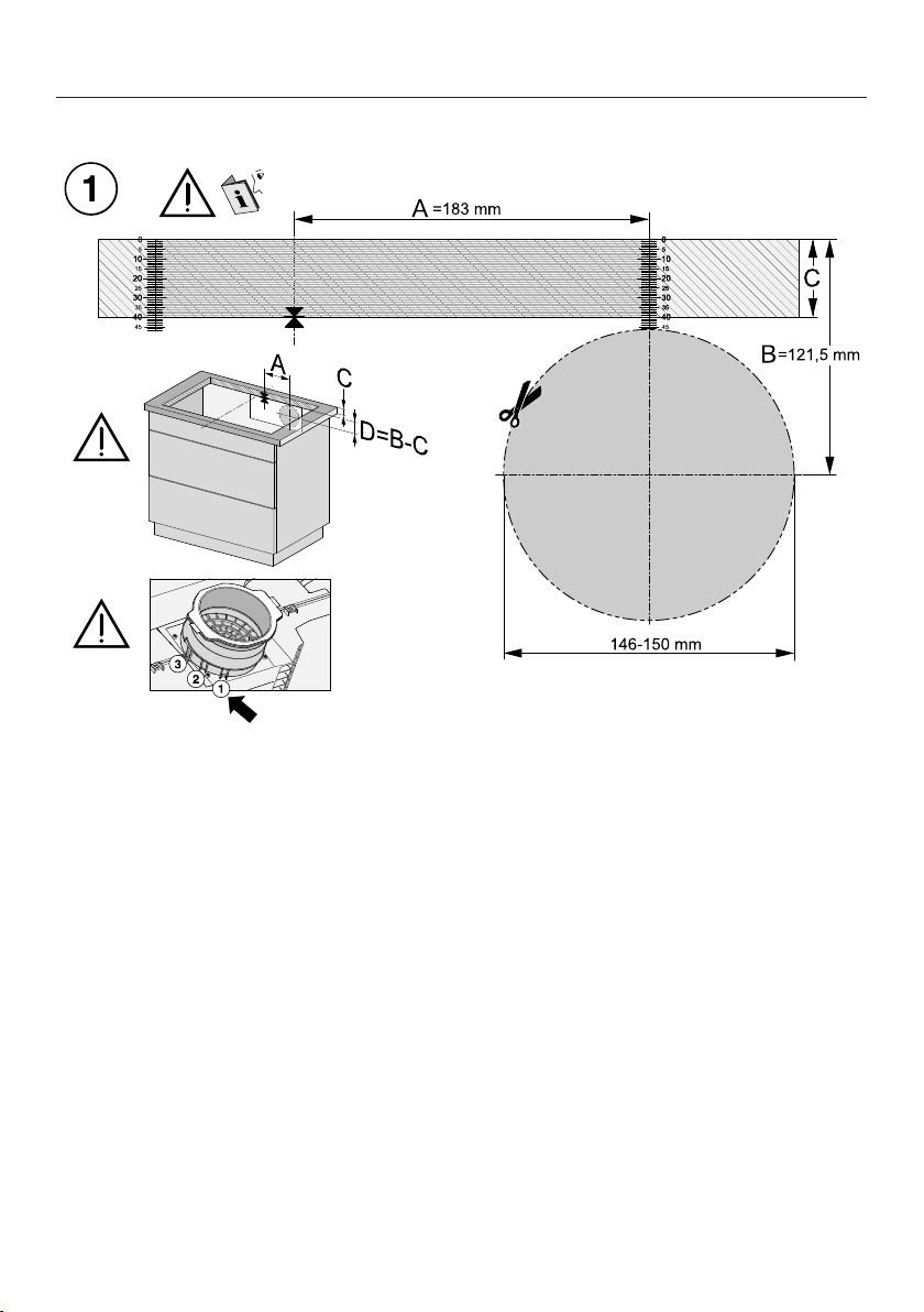
Installation
*INSTALLATION*
101
Flush-fit installation
View of the drilling template side 1. Not to scale.
Measure the thickness of your worktop (C).
Determine the midpoint of the longest side of the cut-out.
Mark the point that is 183mm (A) to the right of the midpoint.
Mark the point (D) that is (121.5mm – C (thickness of the worktop)) below the
right end of distance A.
Saw a hole with a diameter of 146–150mm around this point.
Plug&Play mode only: engage the Plug&Play adapter in position1.
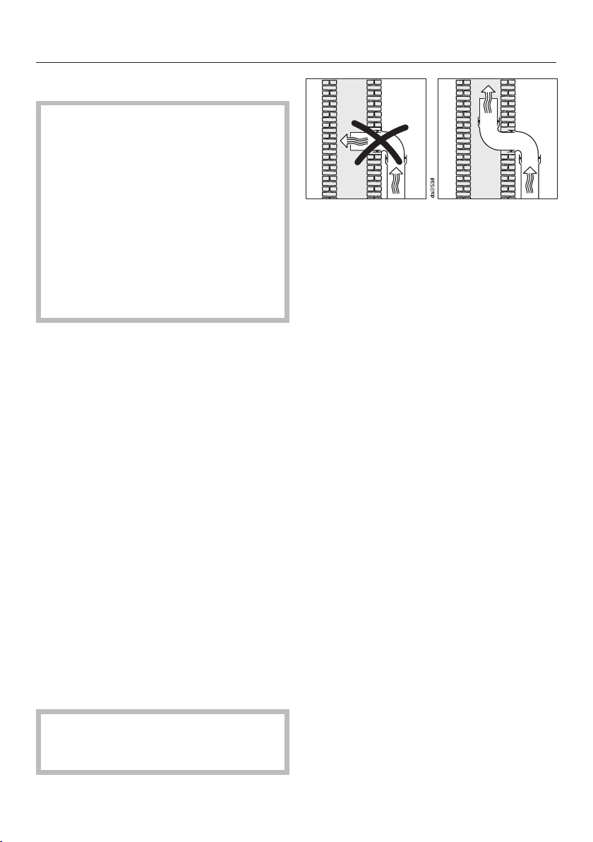
Installation
*INSTALLATION*
102
Ducting
If the vapour extraction is used
at the same time as a heating appli-
ance that relies on oxygen from the
same room, there is a risk of toxic
fumes.
It is essential that the “Warnings and
safety instructions” are observed.
The vapour extraction should be in-
stalled according to local and na-
tional building regulations. Seek ap-
proval from the building regulations
inspector where necessary.
The vapour extraction has an exhaust
duct of ⌀ 150mm.
Only use smooth pipes or flexible ex-
haust hoses made from non-flam-
mable materials for exhaust ducting.
To achieve the most efficient air
throughput with the lowest noise
levels, please note the following:
- The cross-section of the exhaust
ducting must not be smaller than the
cross-section of the exhaust connec-
tion (see the appliance dimensions).
- The ducting should be as short and
straight as possible.
- Only use wide radius bends.
- The exhaust ducting must not be
kinked or compressed.
- Ensure that all connections are
strong and airtight.
Remember that any constriction of
the air flow will reduce air throughput
and increase operating noise.
If the exhaust air is to be ducted into
a flue, the ducting must be directed in
the flow direction of the flue.
If ducting is to be laid horizontally it
must be laid with a downwards slop-
ing gradient. This is to ensure that
condensate cannot drain back into
the fan.
If the ducting is to run through cool
rooms, ceiling space, etc. there may
be great variations in temperature
between the different areas. The
problem of condensation will need to
be addressed. The ducting will need
to be suitably insulated.
Installation
*INSTALLATION*
103
Electrical connection
Risk of damage from incorrect
connection.
Unauthorised installation, mainten-
ance and repairs can cause consid-
erable danger for the user.
Miele cannot be held liable for dam-
age or injury caused by unauthorised
installation, maintenance or repair
work, or by an inadequate or faulty
on-site earthing system (e.g. electric
shock).
This hob must be connected to the
electrical supply by a qualified elec-
trician.
The electrician must be familiar with
and comply with the national regula-
tions and any additional regulations
of the local electricity provider (e.g.
BS 7671 in the UK).
After installation, ensure that all elec-
trical components are shielded and
cannot be accessed by users.
Total power rating
See data plate
Connection data
The connection data is quoted on the
data plate. Please ensure these match
the household mains supply.
Please see wiring diagrams for connec-
tion. (N.B. This appliance is supplied
single phase only in the UK / AUS / NZ).
Residual current device
For extra safety, it is advisable to pro-
tect the appliance with a suitable resid-
ual current device (RCD) with a trip
range of 30 mA.
WARNING
THIS APPLIANCE MUST BE
EARTHED
Disconnecting devices
It must be possible to disconnect the
hob from the mains at all poles using
disconnecting devices. A contact dis-
tance of at least 3mm must be ob-
served in the switched-off state. The
disconnecting devices are overcurrent
protection devices and residual current
protection devices.
Installation
*INSTALLATION*
104
Disconnecting from the mains
Risk of electric shock.
There is a risk of electric shock if the
appliance is connected to the mains
supply during repair or service work.
After disconnection, ensure the ap-
pliance cannot be switched back on
by mistake.
To disconnect the appliance from the
mains power supply, do one of the fol-
lowing depending on installation:
Safety fuses
Completely remove fuses.
Automatic circuit breakers
Press the (red) test button until the
middle (black) button springs out.
Built-in circuit breakers
Circuit breakers at least type B or C:
Switch the lever from 1 (on) to 0 (off).
Residual current device (RCD)
Switch the main switch from 1 (on) to
0 (off) or press the test button.
Mains connection cable
The hob must be connected to the elec-
trical supply with a special connection
cable, type H05VV-F (PVC insulated)
with a suitable diameter.
Please see wiring diagrams for connec-
tion. (N.B. This appliance is supplied
single phase only in the UK / AUS / NZ).
See the data plate on the hob for the
correct voltage and rated load.
Replacing the mains connection
cable
Risk of electric shock.
Incorrect connection to the power
supply may result in an electric
shock.
The mains cable must only be re-
placed by a qualified electrician.
When replacing the mains cable only
use cable type H05VV-F (PVC insu-
lated) with a suitable cross section. A
suitable connection cable is available to
order from Miele.
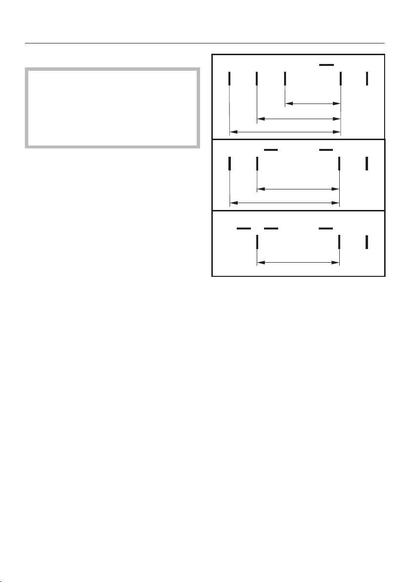
Installation
*INSTALLATION*
105
Wiring diagram
Some connection methods are not
permitted in all installation locations.
Ensure compliance with national reg-
ulations and any additional regula-
tions issued by the local electricity
provider.
L1
200-240 V~
200-240 V~
200-240 V~
abcde-
L2 L3 N
-
L2
b
L1
acd
N
e
(L3)
200-240 V~
200-240 V~
a
L1
bcd
N
e-
(L2)
200-240 V~
After sales service
106
Contact in the event of a fault
In the event of any faults which you cannot remedy yourself, please contact your
Miele dealer or the Miele Customer Service Department.
You can book a Miele Customer Service Department call-out online at
www.miele.com/service.
Contact information for the Miele Customer Service Department can be found at
the end of this document.
Please quote the model identifier and serial number of your appliance (Fabr./SN/
Nr.) when contacting the Miele Customer Service Department. This information
can be found on the data plate.
Please note that telephone calls may be monitored and recorded for training pur-
poses and that a call-out charge will be applied to service visits where the problem
could have been resolved as described in this booklet.
Data plate
Stick the extra data plate supplied with the appliance here. Make sure that the
model number matches the one specified on the back cover of this document.
Warranty
For information on the appliance warranty specific to your country please contact
Miele. See back cover for address.
In the UK, your appliance warranty is valid for 2 years from the date of purchase.
However, you must activate your cover by calling 0330 160 6640 or registering on-
line at www.miele.co.uk.
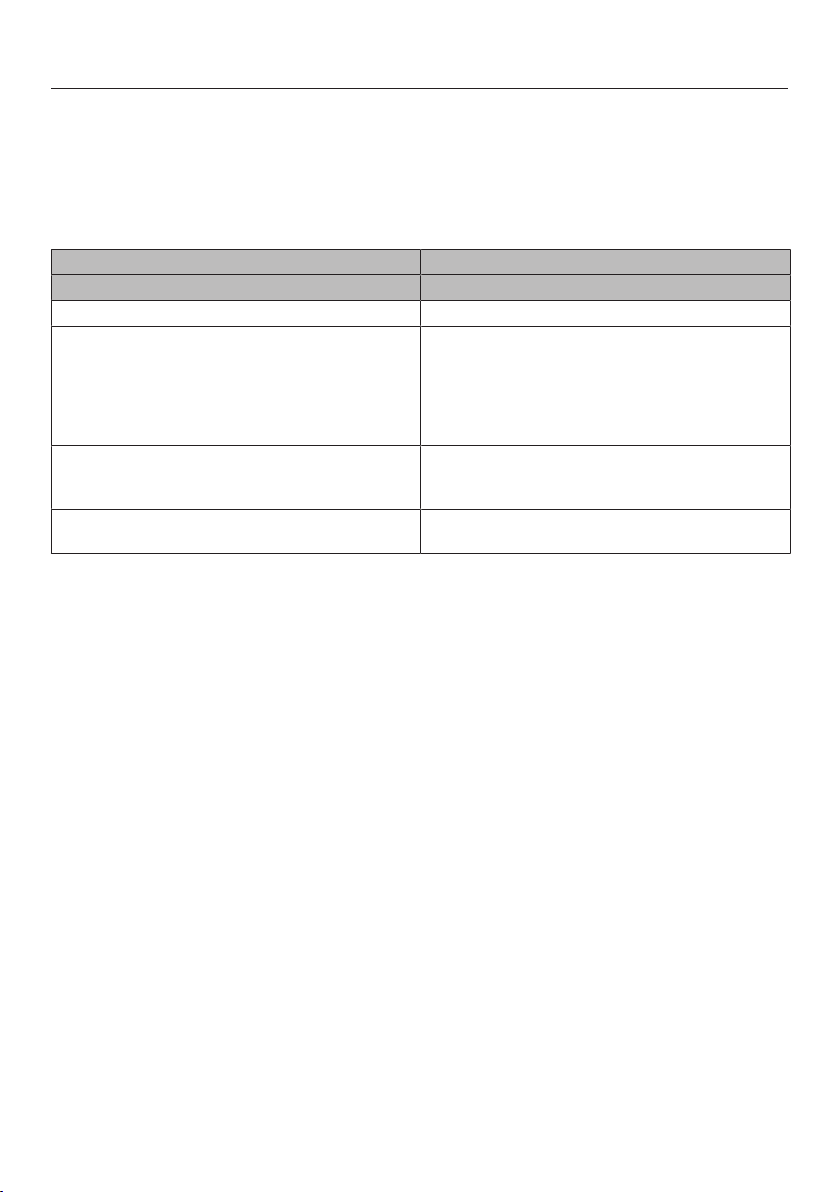
Product data sheets
107
The following data sheets apply to the models described in this operating instruc-
tion manual.
Information for domestic electric hobs
In acc. with regulation (EU) No. 66/2014
MIELE
Model name/identifier KMDA 7473
Number of cooking zones and/or areas 4
For circular cooking zones: diameter of useful sur-
face area/cooking zone
For non-circular cooking zones or areas: length
and width of useful surface area per electric cook-
ing zone or area
1. = 210x420 mm
2. = 210x420 mm
3. =
4. =
5. =
6. =
Energy consumption per cooking zone or area cal-
culated per kg (ECelectric cooking)
1. = 177,7 Wh/kg
2. = 177,8 Wh/kg
Energy consumption for the hob calculated per kg
(ECelectric hob)
177,7 Wh/kg
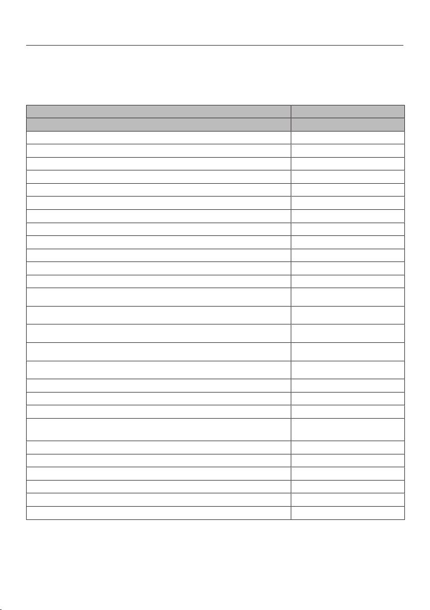
Product data sheets
108
Data sheet for household cooker hoods
In acc. with delegated regulation (EU) No. 65/2014 and regulation (EU) No.
66/2014
MIELE
Model name/identifier KMDA 7473
Annual Energy Consumption (AEChood) 31,5 kWh/year
Energy efficiency class A+
Energy efficiency index (EEIhood) 38,0
Fluid Dynamic Efficiency (FDEhood) 35,8
Fluid Dynamic Efficiency class
A (most efficient) to G (least efficient) A
Lighting Efficiency (LEhood) lx/W
Lighting Efficiency class
A (most efficient) to G (least efficient) -
Grease Filtering Efficiency 95,1%
Grease Filtering Efficiency class
A (most efficient) to G (least efficient) A
Airflow at best efficiency point 321,0 m3/h
Air flow (min. speed) 195 m3/h
Air flow (max. speed) 538 m3/h
Air flow (intensive or boost setting) 615 m3/h
Max. air flow (Qmax)615 m3/h
Air pressure at best efficiency point 494 Pa
Airborne acoustical A-weighted sound power emissions (min. speed) 41 dB
Airborne acoustical A-weighted sound power emissions (max. speed) 64 dB
Airborne acoustical A-weighted sound power emissions (intensive or
boost setting)
67 dB
Electrical power input at best efficiency point 123,1 W
Power consumption in off mode (Po) W
Power consumption in standby mode (Ps) 0,22 W
Nominal power of lighting system 0,0 W
Average illumination of the lighting system on the cooking surface 0 Ix
Time increase factor 0,7

UK Conformity declaration
109
Miele hereby declares that this ceramic
induction hob complies with UK Radio
Equipment Regulations 2017, as
amended.
The complete text of the UK declaration
of conformity is available from one of
the following internet addresses:
- Products, Download from
www.miele.co.uk
- For service, information, operating in-
structions etc: go to
www.miele.co.uk and enter the name
of the product or the serial number
Frequency band
of the WiFi mod-
ule
2.4000GHz –
2.4835GHz
Maximum trans-
mitting power of
the WiFi module
<100mW


United Kingdom
Miele Co. Ltd., Fairacres, Marcham Road, Abingdon, Oxon, OX14 1TW
Tel: 0330 160 6600, Internet: www.miele.co.uk/service, E-mail: [email protected]
Australia
Miele Australia Pty. Ltd.
ACN 005 635 398
ABN 96 005 635 398
Level 4, 141 Camberwell Road
Hawthorn East, VIC 3123
Tel: 1300 464 353
Internet: www.miele.com.au
Miele Electrical Appliances Co., Ltd.
1-3 Floor, No. 82 Shi Men Yi Road
Jing' an District
200040 Shanghai, PRC
Tel: +86 21 6157 3500
Fax: +86 21 6157 3511
E-mail: [email protected],
Internet: www.miele.cn
China Mainland
Miele (Hong Kong) Ltd.
41/F - 4101, Manhattan Place
23 Wang Tai Road
Kowloon Bay, Hong Kong
Tel: (852) 2610 1025
Fax: (852) 3579 1404
Email:
Website: www.miele.hk
Hong Kong, China
Miele India Pvt. Ltd.
1st Floor, Copia Corporate Suites,
Commercial Plot 9,
Mathura Road, Jasola,
New Delhi - 110025
E-mail: customercare@miele.in
Website: www.miele.in
India
Miele Ireland Ltd.
2024 Bianconi Avenue
Citywest Business Campus
Dublin 24
Tel: (01) 461 07 10
Fax: (01) 461 07 97
E-Mail: [email protected]
Internet: www.miele.ie
Ireland
Malaysia
Miele Sdn Bhd
Suite 12-2, Level 12
Menara Sapura Kencana
Petroleum
Solaris Dutamas No. 1
Jalan Dutamas 1
50480 Kuala Lumpur, Malaysia
Phone: +603-6209-0288
Fax: +603-6205-3768
Miele New Zealand Limited
IRD 98 463 631
8 College Hill
Freemans Bay, Auckland 1011
New Zealand
Tel: 0800 464 353
Internet: www.miele.co.nz
New Zealand
Miele Pte. Ltd.
29 Media Circle
#11-04 ALICE@Mediapolis
Singapore 138565
Tel: +65 6735 1191
Fax: +65 6735 1161
E-Mail: [email protected]
Internet: www.miele.sg
Singapore
Miele (Pty) Ltd.
63 Peter Place, Bryanston 2194
P.O. Box 69434, Bryanston 2021
Tel: (011) 875 9000
Fax: (011) 875 9035
E-mail: [email protected]
Internet: www.miele.co.za
South Africa
Miele Appliances Ltd.
Showroom 1, Eiffel 1 Building
P.O. Box 114782 - Dubai
Tel. +971 4 3044 999
Fax. +971 4 3418 852
800-MIELE (64353)
E-Mail: [email protected]
Website: www.miele.ae
United Arab Emirates
Manufacturer: Miele & Cie. KG, Carl-Miele-Straße 29, 33332 Gütersloh, Germany
Thailand
Miele Appliances Ltd.
BHIRAJ TOWER at EmQuartier
43rd Floor Unit 4301-4303
689 Sukhumvit Road
North Klongton Sub-District
Vadhana District
Bangkok 10110, Thailand
Sheikh Zayed Road, Umm Al Sheif
Kuwait
Miele Kuwait
Al Wazzan United Trading Co.
P. O. Box : 3379
Hawally, 32034 Kuwait
Tel.: 00965-22001010
Fax: 00965-24838292
E-mail: [email protected]
Website: www.alwazzanunited.com

M.-Nr. 12 294 640 / 00en-GB
KMDA7473FR‑A,KMDA7473FR‑U,
KMDA7473FL‑A,KMDA7473FL‑U