WWW.BERTAZZONI.COM
BERTAZZONI
INSTRUCTIONS D’INSTALLATION ET D’UTILISATION
HOTTES À FILTRE/ENCASTRABLE
BERTAZZONI
EN
FR
INSTALLATION AND USER MANUAL
LINER/INSERT HOODS
KIN..XT

2
READ AND SAVE THESE INSTRUCTIONS BEFORE YOU START
INSTALLING THIS RANGEHOOD
WARNING: - TO REDUCE THE RISK OF A RANGE TOP GREASE FIRE:
a) Never leave surface units unattended at high settings. Boilovers cause smoking and
greasy spillovers that may ignite. Heat oils slowly on low or medium setting.
b)AlwaysturnhoodONwhencookingathighheatorwhenambeingfood(i.e.Crepes
Suzette, Cherries Jubilee, Peppercorn Beef Flambé).
c) Clean ventilating fans frequently. Grease should not be allowed to accumulate on fan
orlter.
d) Use proper pan size. Always use cookware appropriate for the size of the surface element.
WARNING: - TO REDUCE THE RISK OF INJURY TO PERSONS IN THE EVENT OF A
RANGE TOP GREASE FIRE, OBSERVE THE FOLLOWING*:
a)SMOTHERFLAMESwithaclose-ttinglid,cookiesheet,ormetaltray,thenturnofftheburner.
BECAREFULTOPREVENTBURNS.IftheamesdonotgooutimmediatelyEVACUATE
AND CALL THE FIRE DEPARTMENT.
b) NEVER PICK UP A FLAMING PAN - You may be burned.
c) DO NOT USE WATER, including wet dishcloths or towels - a violent steam explosion will
result.
d) Use an extinguisher ONLY if:
1. You know you have a Class ABC extinguisher, and you already know how to operate it.
2. Thereissmallandcontainedintheareawhereitstarted.
3. Theredepartmentisbeingcalled.
4. Youcanghttherewithyourbacktoanexit.
* Based on "Kitchen Firesafety Tips" published by NFPA
WARNING - TO REDUCE THE RISK OF FIRE OR ELECTRIC SHOCK, do not use this
fan with any solid-state speed control device.
WARNING - TO REDUCE THE RISK OF FIRE, ELECTRICAL SHOCK, OR INJURY TO
PERSONS, OBSERVE THE FOLLOWING:
1. Use this unit only in the manner intended by the manufacturer. If you have any
questions, contact the manufacturer.
2. Before servicing or cleaning unit, switch power off at service panel and lock the
service disconnecting means to prevent power from being switched on acciden-
tally. When the service disconnecting means cannot be locked, securely fasten a
prominent warning device, such as a tag, to the service panel.
CAUTION: For General Ventilating Use Only. Do Not Use To Exhaust Hazardous or
Explosive Materials and Vapors.
WARNING - TO REDUCE THE RISK OF FIRE, ELECTRICAL SHOCK, OR INJURY TO
PERSONS, OBSERVE THE FOLLOWING:
1. InstallationWorkAndElectricalWiringMustBeDoneByQualiedPerson(s)InAccor-
dance With All Applicable Codes And Standards, Including Fire-Rated Construction.
2. Sufcientairisneededforpropercombustionandexhaustingofgasesthrough
theue(chimney)offuelburningequipmenttopreventbackdrafting.Followthe
heating equipment manufacturer's guideline and safety standards such as those
publishedbytheNational FireProtection Association (NFPA),andtheAmerican
SocietyforHeating,RefrigerationandAirConditioningEngineers(ASHRAE),and
the local code authorities.

3
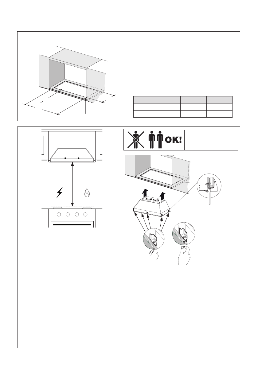
ALL WALL AND FLOOR OPENINGS WHERE THE RANGEHOOD IS INSTALLED MUST BE SEALED.
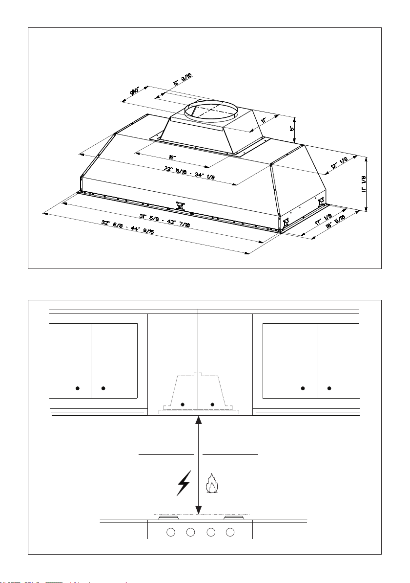
This rangehood requires at least 24" of clearance between the bottom of the rangehood and the
cooking surface or countertop. This hood has been approved by UL at this distance from the cooktop.
This minimum clearance may be higher depending on local building codes. For gas cooktops and combination ranges,
a minimum of 30" is recommended and may be required.
Overhead cabinets on both sides of this unit must be a minimum of 18" above the cooking surface or countertop.
Consult the cooktop or range installation instructions given by the manufacturer before making any cutouts.
MOBILE HOME INSTALLATION The installation of this rangehood must conform to the Manufactured Home
Construction and Safety Standards, Title 24 CFR, Part 3280 (formerly Federal Standard for Mobile Home Construction
and Safety, Title 24, HUD, Part 280). See Electrical Requirements.
• Venting system MUST terminate outside the home.
• DO NOT terminate the ductwork in an attic or other enclosed space.
• DO NOT use 4" laundry-type wall caps.
• Flexible-type ductwork is not recommended.
• DO NOT obstruct the ow of combustion and ventilation air.
• Failure to follow venting requirements may result in a re.
WARNING
!
VENTING REQUIREMENTS
Determine which venting method is best for your application. Ductwork can extend either through the wall or the roof.
The length of the ductwork and the number of elbows should be kept to a minimum to provide efcient performance. The
size of the ductwork should be uniform. Do not install two elbows together. Use duct tape to seal all joints in the ductwork
system. Use caulking to seal exterior wall or oor opening around the cap.
Flexible ductwork is not recommended. Flexible ductwork creates back pressure and air turbulence
that greatly reduces performance.
Make sure there is proper clearance within the wall or oor for exhaust duct before making cutouts. Do not cut a joist or
stud unless absolutely necessary. If a joist or stud must be cut, then a supporting frame must be constructed.
WARNING - To Reduce The Risk Of Fire, Use Only Metal Ductwork.
CAUTION-Toreduceriskofreandtoproperlyexhaustair,besuretoductairoutside–Do
not vent exhaust air into spaces within walls or ceilings or into attics, crawl spaces, or garages.
1. When cutting or drilling into wall or ceiling, do not damage electrical wiring and
other hidden utilities.
2. Ducted fans must always be vented to the outdoors.
Cold Weather installations
An additional back draft damper should be installed to minimize backward cold air ow and a nonmetallic thermal
break should be installed to minimize conduction of outside temperatures as part of the vent system. The damper
should be on the cold air side of the thermal break. The break should be as close as possible to where the vent
system enters the heated portion of the house.
4
• Electrical ground is required on this rangehood.
• If cold water pipe is interrupted by plastic, nonmetallic gaskets or other materials, DO NOT use for
grounding.
• DO NOT ground to a gas pipe.
• DO NOT have a fuse in the neutral or grounding circuit. A fuse in the neutral or grounding circuit could
result in electrical shock.
• Check with a qualied electrician if you are in doubt as to whether the rangehood is properly grounded.
• Failure to follow electrical requirements may result in a re.
WARNING
!
StateofCaliforniaProposition65Warning(USonly)
WARNING
This product contains chemicals known to the State of California to cause cancer and birth defects or other
reproductive harm.
For more information go to www.P65Warnings.ca.gov
ELECTRICAL REQUIREMENTS
A 120 volt, 60 Hz AC-only electrical supply is required on a separate 15 amp fused circuit. A time-delay fuse or circuit breaker
is recommended. The fuse must be sized per local codes in accordance with the electrical rating of this unit as specied
on the serial/rating plate located inside the unit near the eld wiring compartment.
5
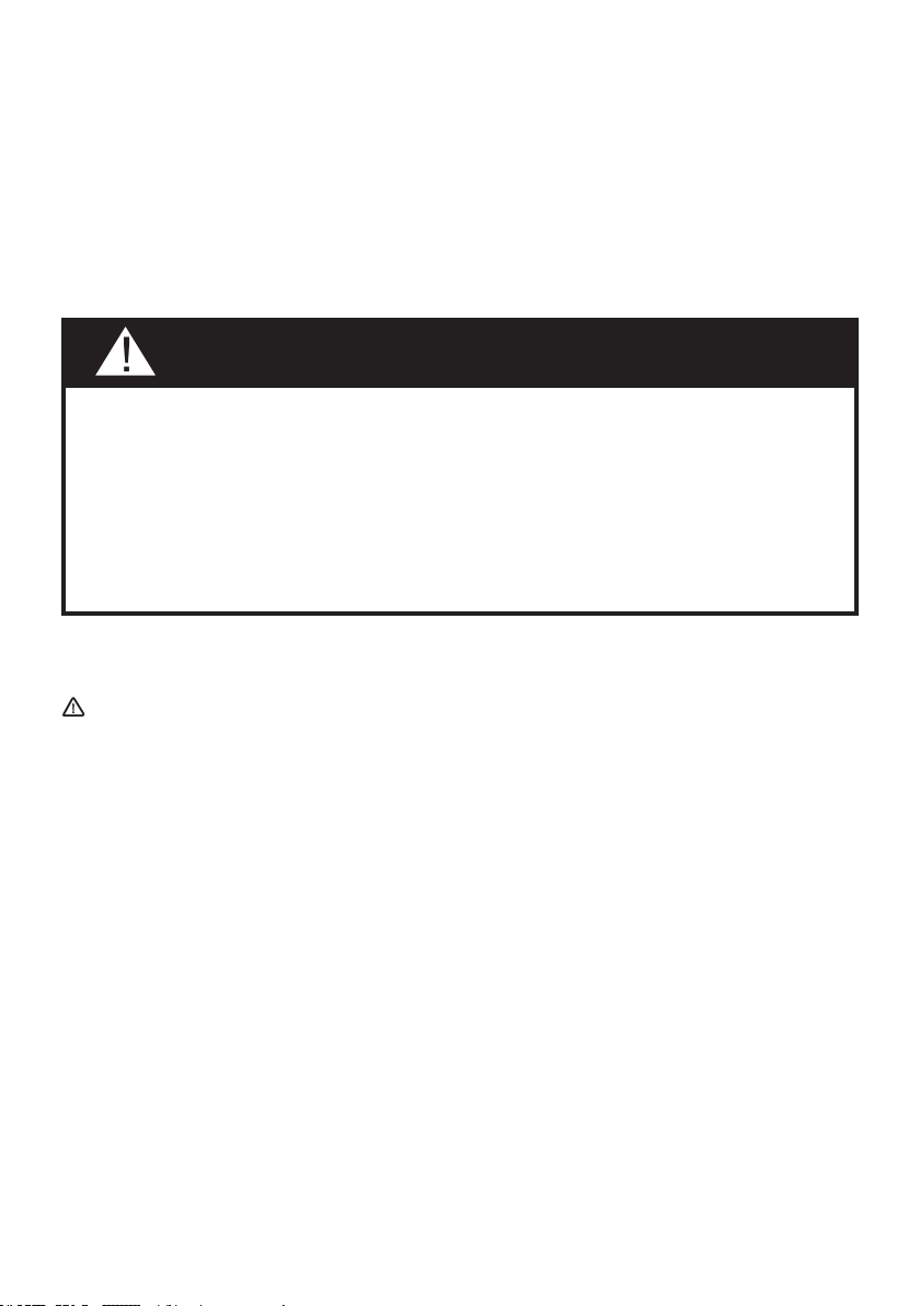
KIN36XT - KIN48XT
RANGEHOOD DIMENSIONS
DRAFT 20-JAN-2021 11:54
Min. 24" Min. 30"
6
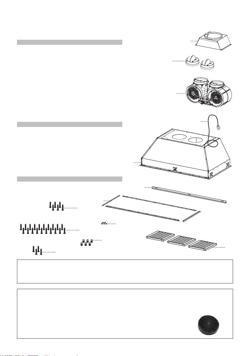
Available Accessories
Charcoal Filter kit sku #901531
Durable charcoal lter kit sku #901532
Remote Control Accessory sku #901575
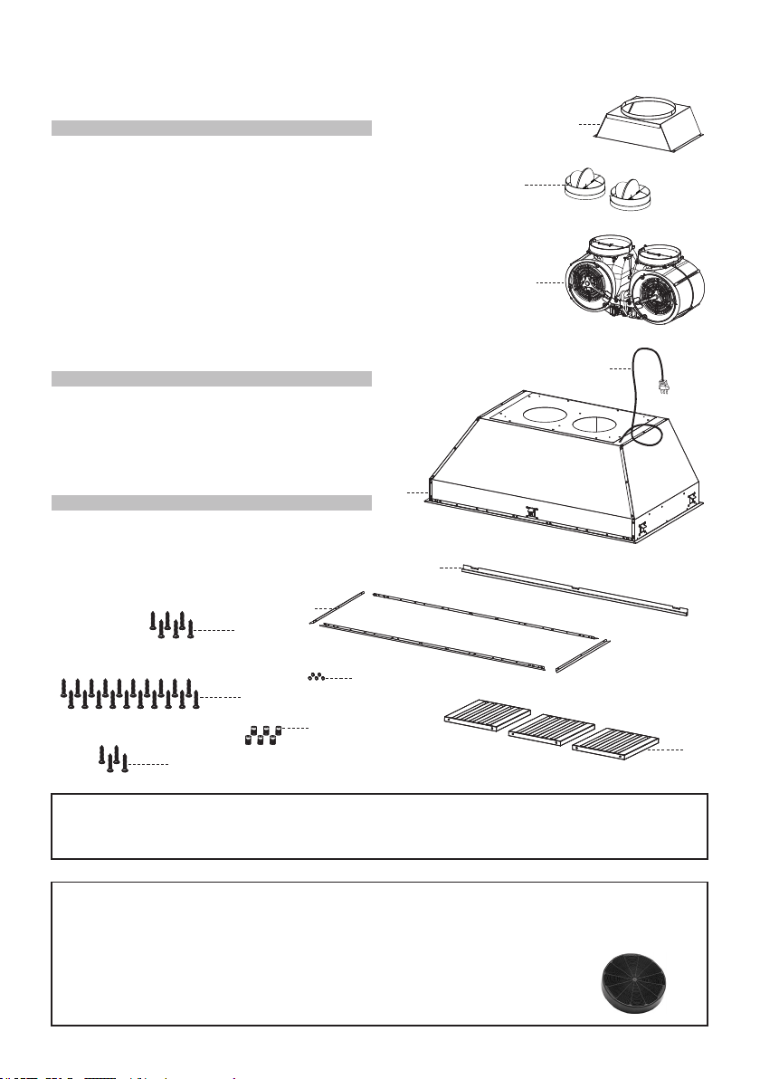
MAIN PARTS
Components
Ref. Qty. Product Components
1 1 Hood Body, complete with:
Controls, Light, Filters, Blower.
2 1 Power cord
3 1 Blower
4 1 Grease rail
5 4 Left/right trim
6 1 Duct transition
7 6 Filter knobs (36" version)
7 8 Filter knobs (48" version)
9 3 Grease lters (36" version)
9 4 Grease lters (48" version)
10 5 Stopper
10.1 2 Damper ø 5 7/8"
Ref. Qty. Installation Components
9c 22 Install screws (1/8"x1/4") (36" version)
9c 26 Install screws (1/8"x1/4") (48" version)
9c 4 Install screws (1/8"x1/4")
9e 6 Grease lters screws 5/32" x 5/16" (36" version)
9e 8 Grease lters screws 5/32" x 5/16" (48" version)
9f 4 Screws 3/16" x 3/8"
Qty. Documentation
1 Instruction Manual
Parts needed
- 10" Round Metal ductwork.
1
3
6
4
5
2
7
9
9e
9c
10
H
I
H
I
10.1
9f
7
FOR ALL INSTALLATIONS REMOVE ALL WHITE PLASTIC PROTECTIVE COVERING FROM
HOOD, SIDE RAILS, TRIM, GREASE RAILS AND GREASE FILTERS.
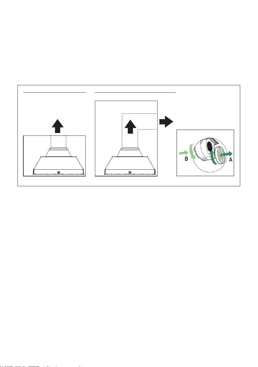
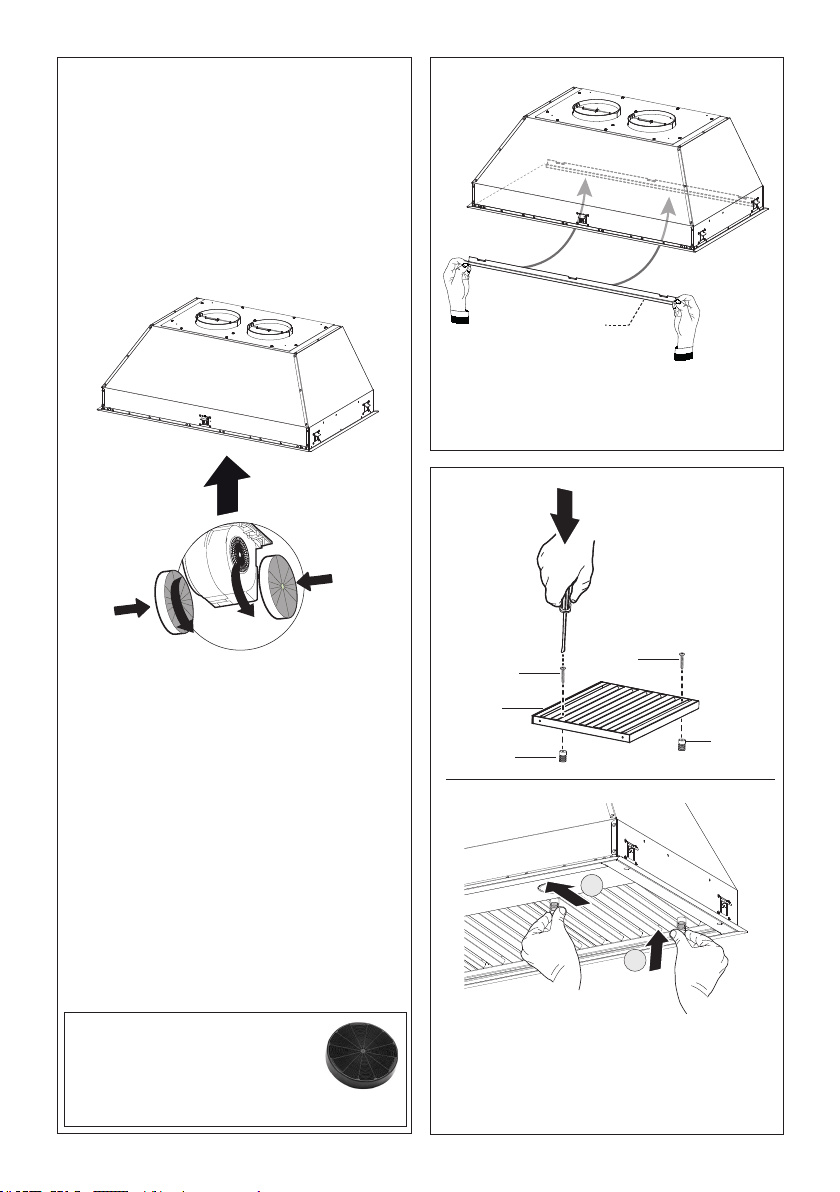
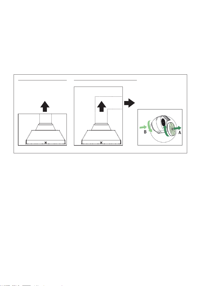
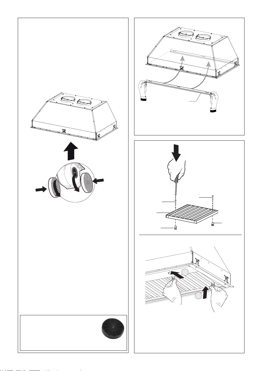
RECIRCULATING INSTALLATIONS
IT IS HIGHLY RECOMMENDED THAT PROFESSIONAL STYLE COOKING ALWAYS BE VENTED
TO THE OUTSIDE. For recirculating installations (Figure 1), Charcoal Filters are necessary. Remove
all grease lters and set aside. Attach one charcoal lter to each end of the blower. Each charcoal lter
attaches to the grid on the side of the blower. Rotate the lter clockwise to install and counterclockwise
to remove (Figure 1A). Replace all grease lters. Recirculating installations also require some duct work
to divert the air out of the top or face or side of the cabinet or custom hood or out of the side / face of
the soft and back into the kitchen. Install at least 15" of vertical run of metal duct (Figure 1) at the air
outlet. Run the duct vertically and secure it at the relevant opening previously cut out at the top or side
of the cabinet or soft. A metal duct cover grille is also recommended. The duct work must not terminate
inside the cabinet or custom hood.
FIGURE 1
cabinet
or
custom
hood
ceiling
duct
work
cabinet
or
custom
hood
ceiling
duct
work
Version 07/11 - Page 7
PLAN YOUR DUCTWORK
To ensure that the blower performs to its highest
possible capacity, ductwork should be as short
and straight as possilbe.
The ductrun should not exceed 35 equivalent
feet if ducted using the required minimum of 6"
round duct. For 10" round ducting with the 1200
cfm internal motor or 900 / 1200 remote blower,
use 55 equivalent feet. Calculate the length of
the ductwork by adding the equivalent feet in
FIGURE 5 for each piece of duct in the system
An example is given in FIGURE 6.
For best results, use no more than three 90°
elbows. Make sure that there is a minimum of
24" of straight duct between elbows if more
than one is used. Do not install two elbows
together. If you must elbow right away, do it
as far away from the hood's exhaust opening
as possible.
9 Feet Straight Duct
2 - 90˚ Elbows
Wall Cap
Total System
9.0 feet
10.0 feet
0.0 feet
19.0 feet
FIGURE 6
3.0 feet
5.0 feet
12.0 feet
0.0 feet
45˚ Elbow
90˚ Elbow
90˚ Flat Elbow
Wall Cap
FIGURE 5
FIGURE 4
RECIRCULATING INSTALLATIONS
IT IS HIGHLY RECOMMENDED THAT PROFESSIONAL STYLE COOKING ALWAYS BE VENTED TO THE OUTSIDE. For recirculating
installations (FIGURE 4), Charcoal Filters are necessary. Remove all grease filters and set aside. Attach one charcoal filter to each end
of the blower. Each charcoal filter attaches to the grid on the side of the blower. Rotate the filter clockwise to install and counterclockwise
to remove (FIGURE 4A). Replace all grease filters. Recirculating installations also require some duct work to divert the air out of the top or
face or side of the cabinet or custom hood or out of the side / face of the soffit and back into the kitchen. Install at least 15" of vertical run of
metal duct (FIGURE 4) at the air outlet. Run the duct vertically and secure it at the relevant opening previously cut out at the top or side of
the cabinet or soffit. A metal duct cover grille is also recommended. The duct work must not terminate inside the cabinet or custom hood.
cabinet
or
custom
hood
ceiling
duct
work
duct
work
ceiling
inca pro plus
cabinet
or
custom
hood
MAKE YOUR CUT-OUTS
1. Disconnect and move freestanding range from cabinet opening to provide easier access
to upper cabinet or custom hood. Put a thick, protective covering over cooktop, set-in range
or countertop to protect from damage or dirt.
2. Determine and make all necessary cuts in the wall and/or ceiling for the ductwork. Install
the ductwork before the rangehood.
3. Determine the proper location for the Power Supply Cable. Use a 1
1/4" Drill Bit to make
this hole. Install the cable. Use caulking to seal around the hole. DO NOT turn on the
power until installation is complete.
4. Choose the knock out hole to remove for installing the power cable. Use a screwdriver
to snap off the knock out covering. (FIGURE 7 shows inside the wiring box and outside)
FIGURE 4A
inca pro plus
FIGURE 7
FOR ALL INSTALLATIONS
REMOVE ALL WHITE PLASTIC PROTECTIVE COVERING FROM HOOD, SIDE RAILS,
TRIM, GREASE RAILS AND GREASE FILTERS
FIGURE 1A
8
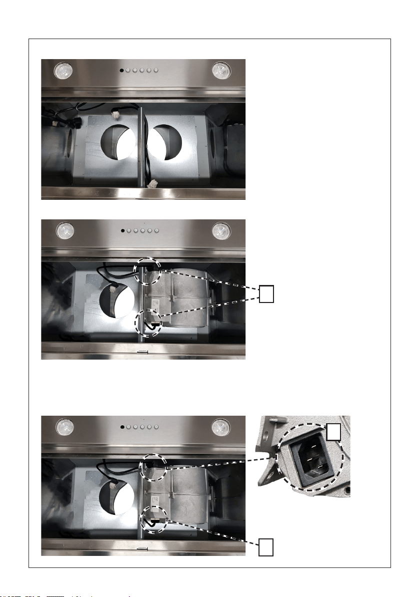
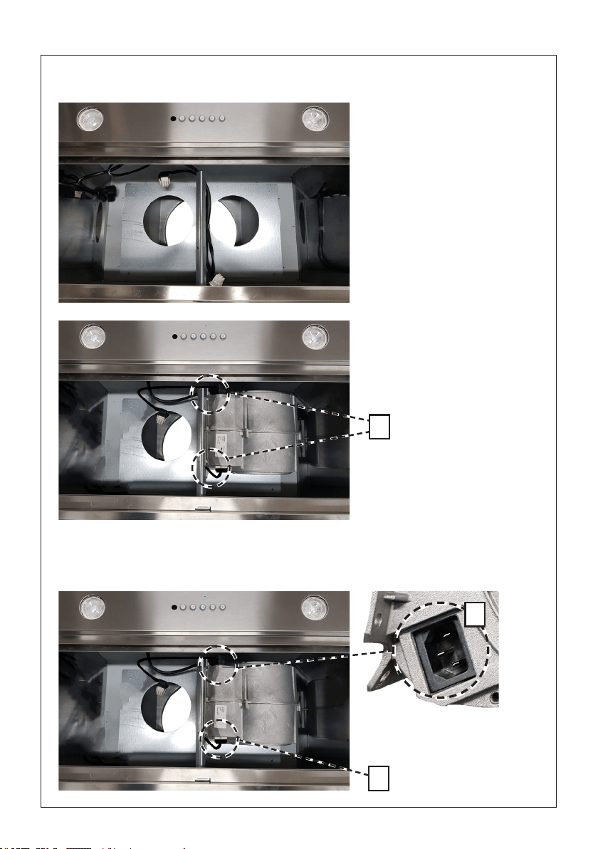
1. Install the 1
st
motor into the sides of the blower bracket using the 2 screws supplied (9f) in position C.
INSTALLATION
c
d
e
2. Plug the 9 way connector on the blower in the position D.
3. Plug the power cable on the blower in the position E.
Detail of the rst blower.
9
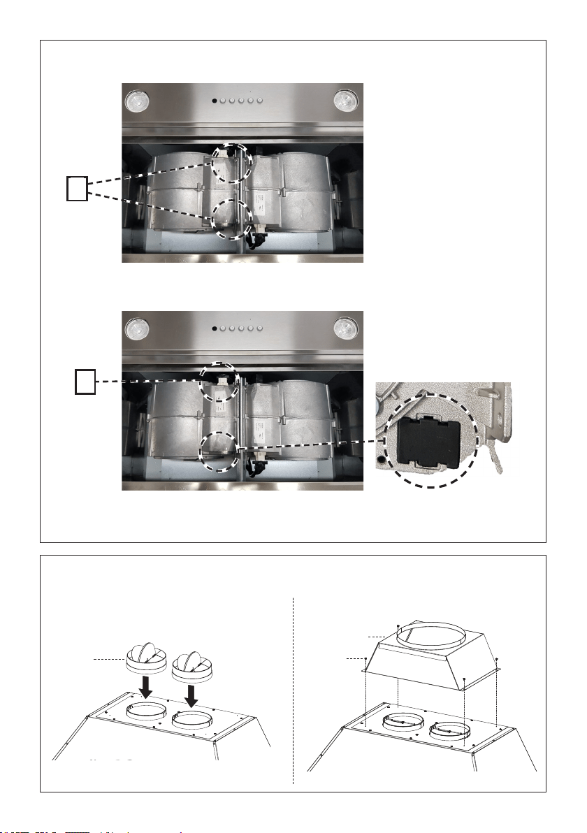
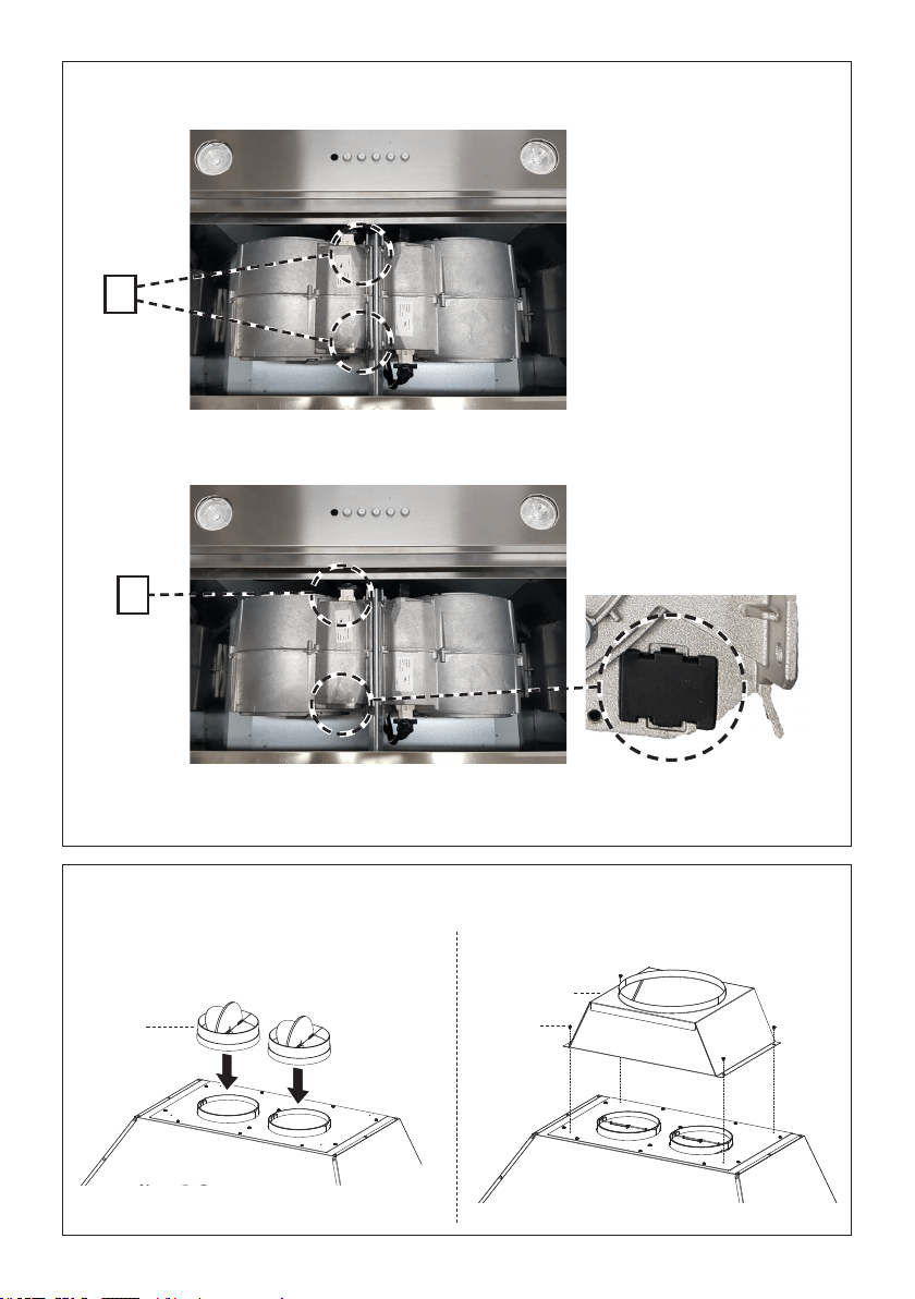
4. Install the 2
nd
motor into the sides of the blower bracket using the 2 screws supplied (9f) in the
position C.
c
6. Connect the damper (10.1) to the motors.
Install the 10" duct transition (6) and install with four screws (9c).
6
9c
10.1
5. Plug the 9 way connector on the second blower in position F.
f
Detail of the second blower.

10
5. Follow step 1-2 to connect ducting, and test the electrical connection.
4. Remove the white plastic covering and install the side trim piece (5) to the outside of the hood
using part 9c screws, see the side trim installation in.
5
9c
11
Y
Min. 3/4
"
X
Min.13/16
"
X
Y
Min.13/16
"
Min. 3/4
"
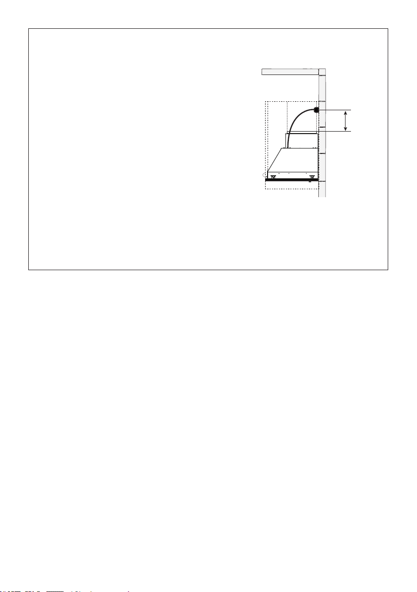
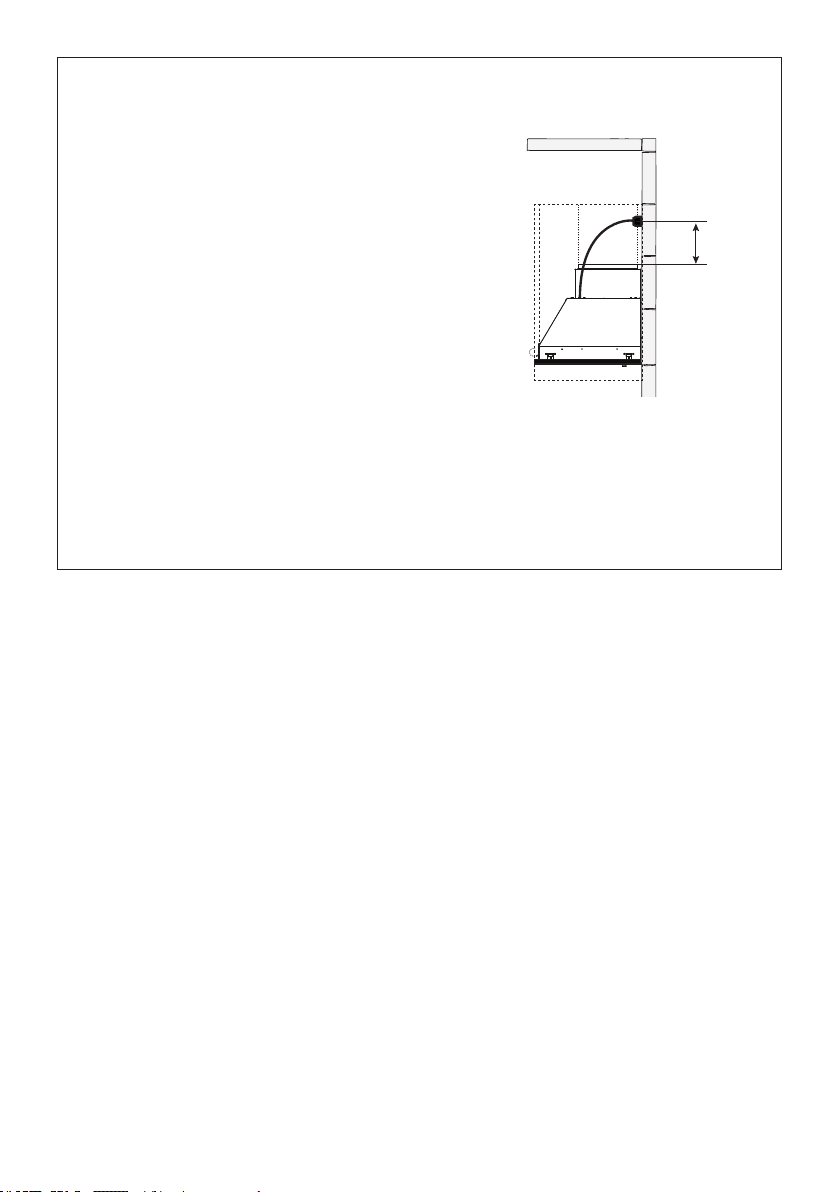
1a
Cut out the opening in the underside of
the cabinet as shown in Figure 1a.
Installation Instructions
1b
It is recommend that the Insert Hood is supported by a 3/4" wood base to insure Side Mount
Clip alignment.
Minimum cabinet opening height-16". However height may vary to allow for ducting.
Install the Insert Hood into the cabinet opening, and fully engage the four spring-loaded Side
Mount Clips onto the cabinet wood base.
Next from underneath the Insert as shown in Figure A, locate the screw in each of the Side
Mount Clips.
To lock the Insert Hood into position, tighten the screw for each of four Side Mount Clips.
Next from underneath the Insert Hood Place the four plastic stoppers (10) as shown in Figure B.
Model # X Y
KIN36XT 31-7/8" 17-3/8"
KIN48XT 43-11/16" 17-3/8"
Two people may be
required for installation.
2x
2x
A
B
10
Min. 24" Min. 30"
12
9e
7
6
9e
7
9
4
2
3
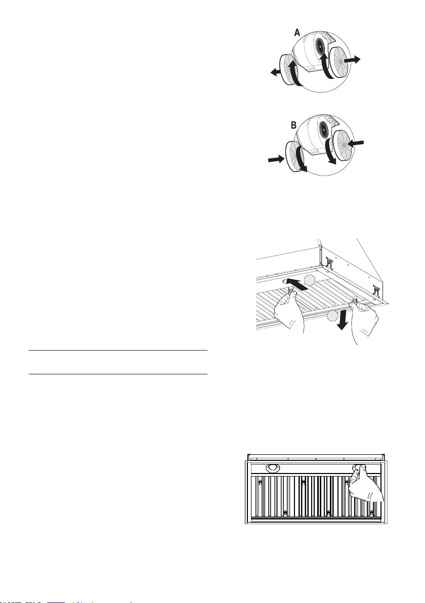
Attach each charcoal lter to the black grid on
each side of the blower. Press the charcoal
lter tightly to the black grid on the blower side
and rotate the lter clockwise (towards the
front of the insert hood) until it locks into place.
Turn counterclockwise (towards the back of
the insert hood) to remove.
For Non-Ducted Recirculation
Option
Required Charcoal Filter kit sku
#901531
Durable charcoal lter kit sku
#901532
(purchased separately)
4
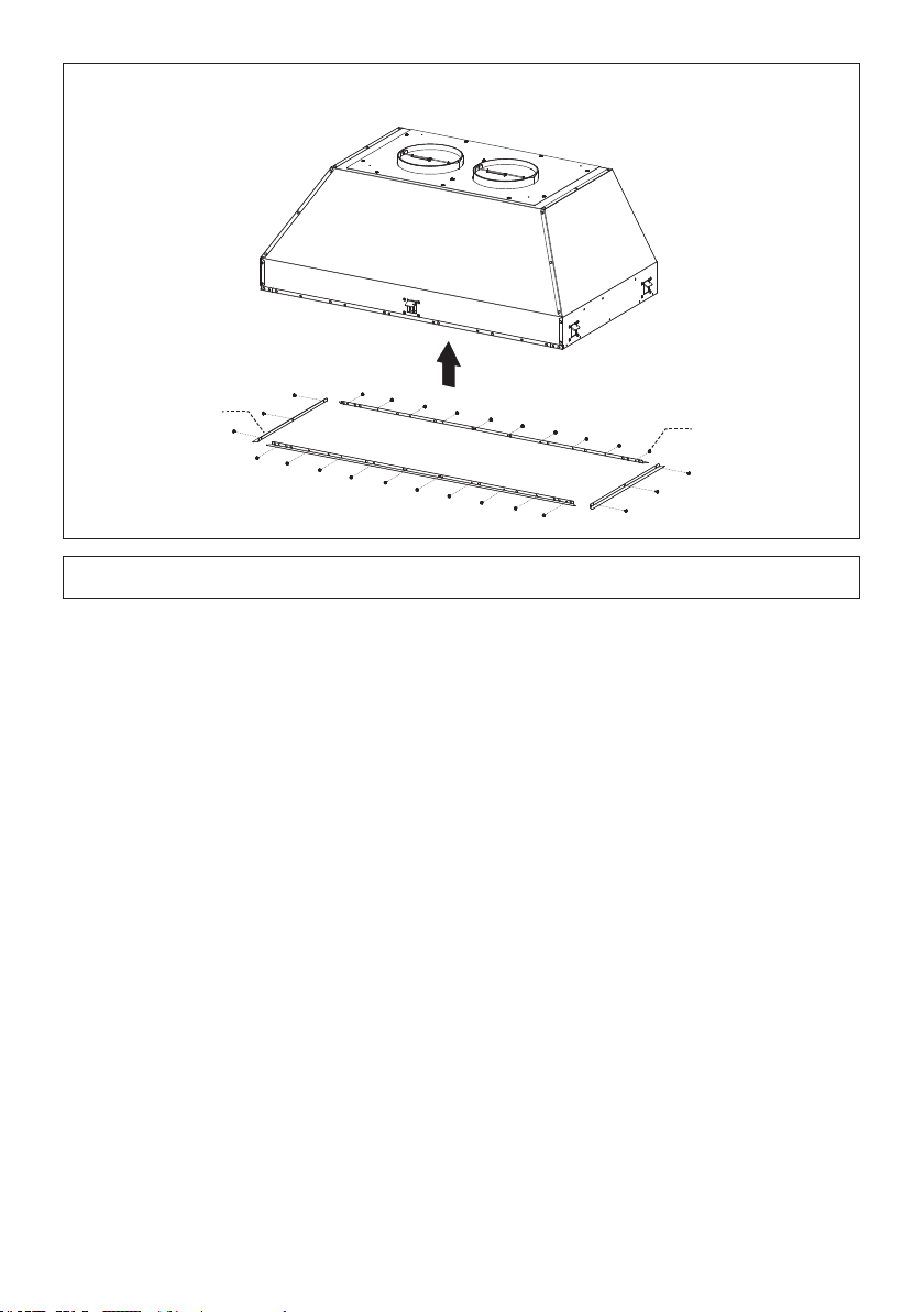
Bafe Filter
Before installing the lters (9), tighten the 2
knobs (7) with 2 screws (9e). Use two hands
to insert and remove the lters.
Hook the Grease rail (4) positioning it inside
the hood. Is possible wash and reposition
inside the hood.
1
2
1
2
13
Max. 33 7/16"
GROUNDING INSTRUCTIONS This appliance must
be grounded. In the event of an electrical short circuit,
grounding reduces the risk of electric shock by providing
an escape wire for the electric current. This appliance
is equipped with a cord having a grounding wire with
a grounding plug. The plug must be plugged into an
outlet that is properly installed and grounded.
WARNING - Improper grounding can result in a risk
of electric shock.
Consult a qualied electrician if the grounding instruc-
tions are not completely understood, or if doubt exists
as to whether the appliance is properly grounded.
Do not use an extension cord. If the power supply cord
is too short, have a qualied electrician install an outlet
near the appliance.
ELECTRICAL INSTALLATION
WITH CONNECTION CABLE
WARNING - "The supply cord shall be accessible for inspection after installation".
5

14
USE AND CARE INFORMATION
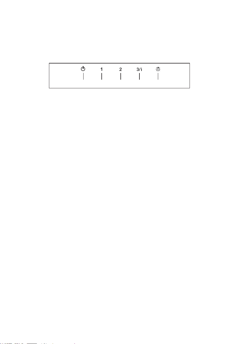
T1 T2 T3 T4 L
LT1 T2 T3 T4
For Best Results
Start the rangehood several minutes before cooking to develop proper airow. Allow the
rangehood to operate for several minutes after cooking is complete to clear all smoke and
odors from the kitchen.
T1. Fan off button:turn the blower Off. The fan can be operated by pressing any of the fan setting buttons.
Hold down this button for 2 seconds to activate Delay off function which will keep the fan on for 15
minutes and automatically shut off.
T2. Fan settings buttons: Low speed.
T3. Fan settings buttons: Medium speed.
T4. Fan settings buttons: High speed / Intensive speed.
Hold down the button for 2 seconds to activate the intensive speed, which is timed to run for 6
minutes. At the end of this time it will automatically return to the speed set before.Suitable to deal
with maximum levels of cooking fumes.
L. Light button: On/Off switch for the lights.
NOTE: If your product has had a CFM adjustment, refer to the CFM adjustment manual for the infor-
mation. Some motor speeds or functions may be reduced.
15
1
2
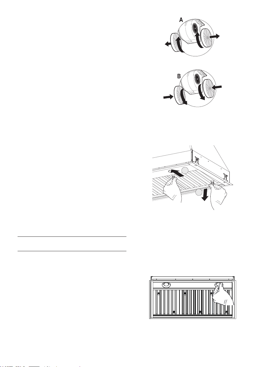
Replacing Activated Charcoal Filter
The Activated Charcoal Filters are not washable
and cannot be regenerated, and should be replaced
approximately every 4 months of operation, or more
frequently with heavy usage.
• Remove the charcoal lter by rotating it clockwise ( backwards)
until it unlocks from the motor housing and pull off sideways.
• To re-insert each charcoal lter, place up against the
side of the blower and push it inward. Then turn the
charcoal lter clockwise (forward) until it ts into place.
Caution: "When used in recirculation mode, to Re-
duce the Risk of Fire and Shock use only conversion
kit Model Charcoal Filter kit sku #901531; Durable
charcoal lter kit sku #901532"
Please contact the retailer that sold you the product to
purchase carbon lters above.
Cleaning
The stainless steel grease lters and grease rail
should be cleaned frequently in hot detergent
solution or washed in the dishwasher. Clean
exterior surfaces with a commercially available
stainless steel cleaner. Abrasives and scouring
agents can scratch stainless steel nishes and
should not be used to clean nished surfaces.
Make sure the grease lters are completely dry
with no water present before re-installing into
hood.
Grease rail and Grease Filter Installation /
Removal.
Remove the plastic from the lter, the knobs
need to be installed onto the lter with 2
screws to each lter.
Install the grease rail into the back of the hood,
into the slots on the inside oor of the rear of the
hood. The Grease lters should be installed before
operating the rangehood. To install the lters, use
the two knobs to hold the lter and insert the lter
into the front edge of the hood with the knobs
facing out into the spring loaded slot. Install the
other end of the lter above the grease rail in the
back of the hood.
Version 07/11 - Page 11
Light On/Off Button (A)
On/Off switch for the halogen lights. Position "0" turns the lights off,
turning the switch to the right one click is the dimmer position, and
the next click to the right is full power
Blower On/Off Button (B)
On/Off switch for the blower. Move the dial to the right to turn the
blower ON and vary the speed of the blower. Turn to the left at "0"
to turn it OFF.
For Best Result
Start the rangehood several minutes before cooking to develop proper
airflow. Allow the unit to operate for several minutes after cooking is
complete to clear all smoke and odors from the kitchen.
Cleaning
The stainless steel grease filters and grease rail should be cleaned
frequently in hot detergent solution or washed in the dishwasher.
Clean exterior surfaces with a commercially available stainless steel
cleaner. Abrasives and scouring agents can scratch stainless steel
finishes and should not be used to clean finished surfaces.
Grease rail and Grease Filter Installation / Removal
Remove the plastic from the filter, the knobs need to be installed
onto the filter with 2 screws to each filter
Install the grease rail into the back of the hood, into the slots on the
inside floor of the rear of the hood. The Grease filters should be
installed before operating the rangehood. To install the filters, use the
two knobs (in FIGURE 28) to hold the filter and insert the filter into
the front edge of the hood with the knobs facing out into the spring
loaded slot. Install the other end of the filter above the grease rail in
the back of the hood.
USE AND CARE INFORMATION
This rangehood system is designed to remove smoke, cooking vapors
and odors from the cooktop area.
Rangehood Control Panel
The control panel is located in the center of the hood bottom. The
position and function of each control button are indicated in FIGURE
27
FIGURE 28
Replacing the Halogen Lamp
Before you begin, make sure that the rangehood is turned off and
that the other lamps have had sufficient time to cool. Halogen lamps
burn extremely hot and serious injury could result from touching a hot
lamp. Press and twist the lamp to remove. Then remove the lamp
and replace with a new lamp.
WIRING DIAGRAM
This rangehood uses 45 watt PAR16
Halogen Lamps.
FIGURE 27
FIGURE 26
ALL INSTALLATIONS
1. Use a drill to install side rails on the inside rangehood walls to
line the inside hood wall with stainless, 2 and 3 in FIGURE 26 with
9a. screws, 4 screws total.
BLK
WHT
R11B41
LIGHT CONTROL
OFF / HALF LIGHT / ON
1
Y-G
A
RED
WIRING BOX
WHT
BLK
BLK
23
B
ORG
WHT
4
VLT
N
L
Y-G
LINE IN
120Vac
60Hz ~
Y-G
BLU
123
654
789
123
654
987
RED
M8 4V
120V ~
WHT
BRW
BLU
BLK
ORG
BLU
BLK
Y-G
Y-G
ON/OFF MOTOR
SPEED CONTROL
BLKBLK
BLU
123
654
789
123
654
987
RED
M8 4V
120V ~
BLU
Y-G
WHT
BRW
BLKBLK
BLU
123
654
123
654
BLK
ORG
Y-G
BLU
WHT
BLK
Y-G
WIRING BOX FOR
REMOTE BLOWER
WHT
REMOTE
BLOWER
123
654
WHT
Y-G
BLKBLK
Y-G
9a
9a
2
3
9a
9a

16
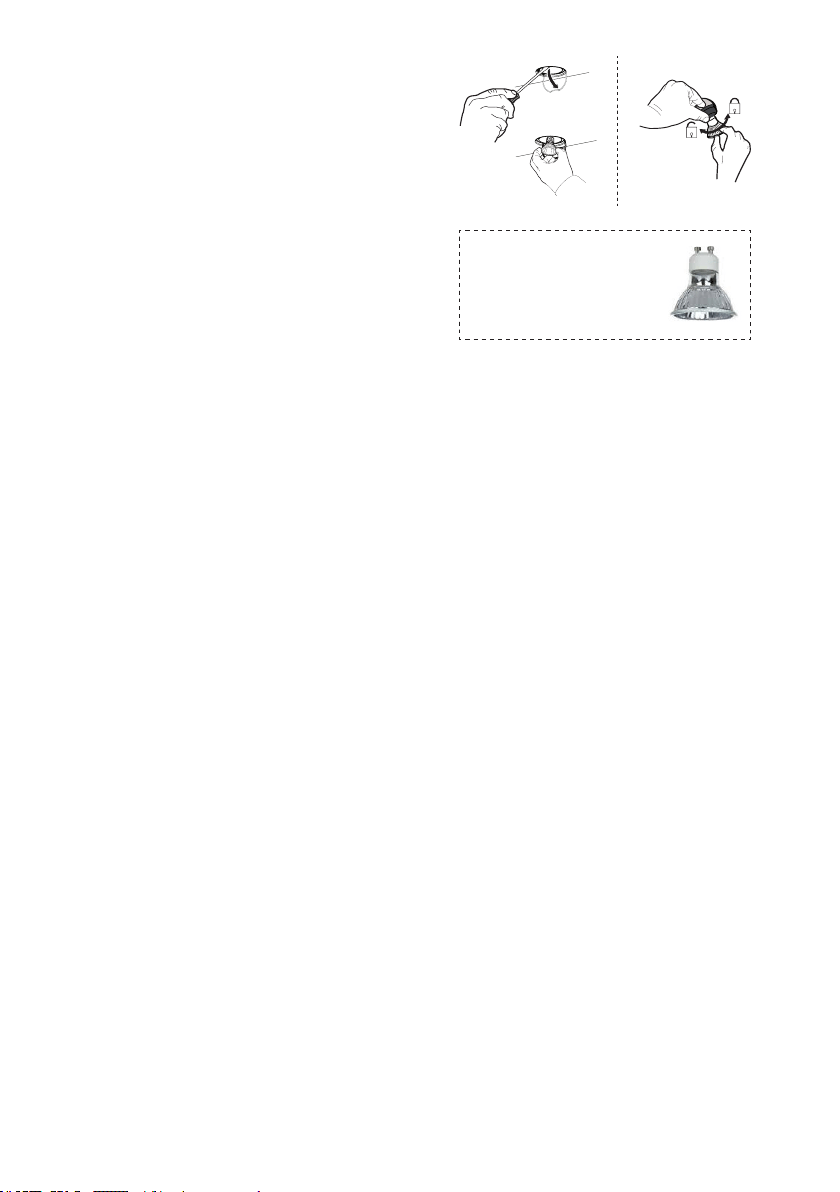
Lighting unit
• Replace the lamp with a new one of the same type,
making sure that you insert the two pins properly
into the housings on the lamp holder.
Gu10 self-ballasted
led lamps – listed in
accordance with ul 1993/
nmx-j-578/1-ance/csa
c22.2 No. 1993
17
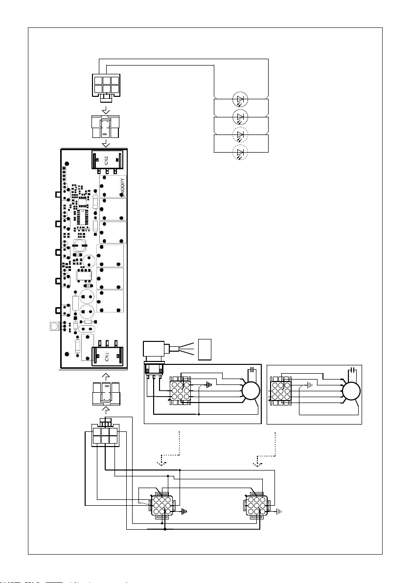
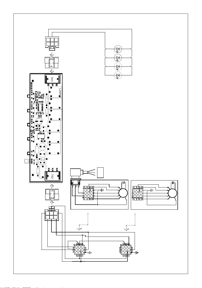
Wiring Diagram
0123456789
H90_972
01
Drawing N : Rev :
Modif. by
These drawings and specifications are the property of Franke Technology and
Trademartk Ltd and shall not be reproduced.copied or trasferred to any third party
without the prior written permission of Franke Tecnology and Trandemark Ltd.
Switzerland.It is strictly prohibited to get quotes from the drawing or bring
modifications without the prior written conset of franke Techology and Trademark
Doc.status
Modification description
Approved date
WIRING DIAGRAM 2 M8-4V SNOOPY LED GU10
Approved by
Denomination
Doc Type
Creation date
31/03/2021
FABER Corrado
Created by
991.0651.017
Code
123
654
789
1 23
654
ORG
SNOOPY
CN1
CN2
123
654
789
110-127V
60Hz
123
654
987
SIDE
INSERT
CABLE
123
654
987
SIDE
INSERT
CABLE
1 23
654
LED
GU10
LED
GU10
LED
GU10
LED
GU10
BRW
GRY
WHT
BLK
BLU
BRW
GRY
ORG
ORG
WHT
BRW
GRY
BLU
ORG
Y-G
PNK
M8-4V
BRW
ORG
BRWWHT
L-BBLU
BLK
GRY
M8-4V
BRW
ORG
PNK
WHT
BLU
BLK
GRY
BLU
ORG

18
25
Please kindly register on our web site www.bertazzoni.com to validate your new product warranty
and help us to assist you better in case of any inconvenience.
TWO YEAR LIMITED WARRANTY
Thewarrantiesprovided byBertazzoniSpainthisstatementapply exclusivelyto Bertazzoniappliancesand
accessories sold as new products to the original owner by a Bertazzoni authorized distributor, retailer, dealer or
service center and installed in the United States and Canada. The warranties provided in this statement are
not transferable and have validity from the date of installation.
COVERAGE INFORMATION
Bertazzoni SpA will repair or replace any component part which fails or proves defective due to materials and/or
workmanship within 2 years from the date of installation and under conditions of normal residential use. Repair
or replacement will be free of charge, including labor at standard rates and shipping expenses. Repair service
must be performed by a Bertazzoni Authorized Service
Center during normal working hours.
COSMETIC WARRANTY
Bertazzoni will cover parts showing cosmetic defects in material and workmanship for a period of thirty (30) days
from date of installation of the unit. This coverage will include scratches, stains, surface imperfections on
stainless steel, paint and porcelain, with the exclusion of slight differences in color due to materials and
painting/enamelling technologies.
Exclusions are labor costs, B stock items, out‐of‐box appliances and display units.
HOW TO
OBTAIN SERVICE
To obtain service please contact Bertazzoni Customer Service at the numbers below and make sure to
have model number, serial number, and date of purchase ready. This information will be requested by our
team and is crucial to speeding up resolution.
UNITED STATES https://us.bertazzoni.com/more/support
Phone: 866-905-0010
CANADA https://ca.bertazzoni.com/more/support
Phone : 800-361-0799
Save proof of original purchase or of original installation to establish warranty period. Copy of the product serial
tag is affixed to the back cover of the instruction manual.
WHAT IS NOT COVERED
1.The product used in any commercial/business application
2.Repair service provided by other than a Bertazzoni authorized service agent.
3.Damage or repair service to correct service provided by an unauthorized agency or the use of
unauthorized parts.
4.Installation not in accordance with local electrical codes or plumbing codes.
5.Defects or damage due to improper storage of the product.
6. Defects or damage or missing parts on products sold out of the original factory packaging or from
displays.
7. Service calls or repairs to correct the installation of the product and/or related accessories.
8. Service calls to connect, convert or otherwise repair the electrical wiring / gas line / water line to
properly use the product.
9. Service calls to provide instructions on the use of a Bertazzoni product.
10. Repair service due to product usage in manner other than what is normal and customary for home use.
11. Replacement of wear and tear parts
12. Replacement of glasses and light bulbs if they are claimed to have failed later than 30 days
after installation and in no case later than 4 months after
date of purchase
13. Defects and damages arising from accident, alteration, misuse, abuse, improper installation.
14. Defects and damages arising from transportation of the product to the home of the owner.
15. Defects and damage arising from external forces beyond the control of Bertazzoni SpA such
as fire, flood, earthquakes and other acts of God.
In case the product will be installed in a remote area, where certified trained technicians are not
reasonably available, the customer will be responsible for the transportation costs for the
delivery of the product to the nearest authorized service center or for the displacement costs of a
certified trained technician.
Bertazzoni does not assume any responsibility for incidental or consequential damages.
Some states do not allow the exclusion or limitation of incidental or consequential damages, so the
above limitation or exclusion may not apply to you. This warranty gives you specific legal rights and you may also
have other rights which may vary from state to state or province to province.

19
VEUILLEZ LIRE ET CONSERVER LA PRÉSENTE NOTICE AVANT DE
COMMENCER L'INSTALLATION DE LA HOTTE DE CUISINE
AVERTISSEMENT:POURRÉDUIRELERISQUED'UNFEUDEGRAISSESURLATABLEDECUISSON:
a) Ne laissez jamais sans surveillance les éléments de la surface de cuisson à température élevée. Les
bouillonnements excessifs peuvent provoquer de la fumée et les débordements de graisse peuvent
s'enflammer. L'huile doit être chauffée lentement, à une température basse ou moyenne.
b) Assurez-vous de toujours mettre en marche le ventilateur de la hotte lorsque vous cuisinez à tem-
pératureélevéeoupréparezunmetsflambé(p.ex.crêpesSuzette,cerisesjubilé,bœufflambé).
c) Nettoyez régulièrement les ventilateurs d'aspiration. Assurez-vous de ne pas laisser de la graisse
s'accumuler sur le ventilateur ou le filtre.
d) Utilisez toujours des poêles et casseroles de la taille appropriée. Utilisez toujours des ustensiles de
cuisine de la taille adaptée à celle de l'élément chauffant.
AVERTISSEMENT:-POURPRÉVENIRLESBLESSURESENCASDEFEUDEGRAISSESURLATABLE
DECUISSON,SUIVEZLESRECOMMANDATIONSSUIVANTES*:
a) ÉTOUFFEZ LES FLAMMES à l'aide d'un couvercle hermétique, d'une plaque à biscuits ou d'un plateau
métallique, puis éteignez le brûleur. FAITES ATTENTION AUX BRÛLURES. Si le feu ne s'éteint pas
immédiatement, QUITTEZ LES LIEUX ET APPELEZ LES POMPIERS.
b) NE PRENEZ JAMAIS UNE CASSEROLE EN FLAMME - Vous pourriez vous brûler.
c) N'UTILISEZ JAMAIS DE L'EAU, ni un linge à vaisselle ou un torchon mouillé, pour éteindre le feu.
Cela pourrait provoquer une violente explosion de vapeur.
d)UtilisezunextincteurUNIQUEMENTsi:
1. Vous êtes certain qu'il s'agit d'un extincteur de classe ABC et que vous connaissez bien son
mode d'emploi.
2. Le feu est de faible intensité et se limite à l'endroit où il a démarré.
3. Les pompiers ont déjà été appelés.
4. Une voie de sortie se trouve derrière vous pendant que vous éteignez les flammes.
* D'après le guide « Kitchen Firesafety Tips » publié par la NFPA aux États-Unis
AVERTISSEMENT - POUR RÉDUIRE LE RISQUE D'INCENDIE OU DE CHOC ÉLECTRIQUE, n'utilisez
jamais ce ventilateur en association avec un dispositif de réglage de vitesse à semi-conducteurs.
AVERTISSEMENT - POUR RÉDUIRE LES RISQUES D'INCENDIE, DE CHOC ÉLECTRIQUE OU DE
BLESSURECORPORELLE,RESPECTEZLESINSTRUCTIONSSUIVANTES:
1. Utilisez cet appareil uniquement de la façon prévue par le fabricant. Pour toute question, com-
muniquez avec le fabricant.
2. Avant de procéder à l'entretien ou au nettoyage de l'appareil, coupez l'alimentation au niveau du
panneau électrique et verrouillez-le pour vous assurer que l'électricité n'est pas rétablie accidentel-
lement. S'il n'est pas possible de verrouiller le dispositif d'interruption de l'alimentation, affichez de
façon ferme et bien visible un avis de danger, par exemple à l'aide d'une étiquette sur le panneau.
ATTENTION:Destinéàunusagedeventilationgénéraleuniquement.N'utilisezpascedispositifpour
l'aspiration de vapeurs ou de matériaux dangereux ou explosifs.
AVERTISSEMENT - POUR RÉDUIRE LES RISQUES D'INCENDIE, DE CHOC ÉLECTRIQUE OU DE
BLESSURECORPORELLE,RESPECTEZLESINSTRUCTIONSSUIVANTES:
1. L'installation et le branchement électrique doivent être réalisés par un technicien qualifié et con-
formément à tous les codes et normes en vigueur, incluant ceux concernant la construction à
l'épreuve du feu.
2. Afin de garantir une combustion et une évacuation adéquates des gaz par les conduites de la che-
minée des appareils à combustion, une bonne aération est nécessaire pour éviter le refoulement.
Respectez les lignes directrices fournies par le fabricant du matériel chauffant, ainsi que les normes
desécuritécommecellespubliéesparlaNationalFireProtectionAssociation(NFPA)etlaAmerican
SocietyforHeating,RefrigerationandAirConditioningEngineers(ASHRAE)auxÉtats-Unis,ainsi
que les codes en vigueur dans votre région.
3. Lorsque vous faites une ouverture ou percez dans un mur ou le plafond, veillez à ne pas endom-
mager les fils électriques ou d'autres dispositifs cachés.
20
4. Les ventilateurs canalisés doivent toujours être raccordés à l'extérieur.
TOUTE OUVERTURE DANS LE MUR OU LE PLANCHER À PROXIMITÉ DE LA HOTTE DOIT ÊTRE
SCELLÉE.
Un espace libre d'au moins 24" est requis entre le bas de la hotte et la surface de cuisson ou le comptoir. Cette hotte
a été homologuée par l'UL à cette distance de la surface de cuisson.
L’espace libre minimal requis peut-être plus grand, selon la réglementation en matière de construction de votre région. Pour les
cuisinières à gaz et les cuisinières combinées, un espace minimal de 30" est recommandé et pourrait être exigé.
Les armoires suspendues de chaque côté de l'appareil doivent se trouver à au moins 18" de la surface de cuisson ou du comptoir.
Consultez la notice d'installation de la surface de cuisson ou de la cuisinière fournie par le fabricant avant de pratiquer des ouvertures.
INSTALLATION DANS UNE MAISON MOBILE L'installation de cette hotte doit être conforme à la Partie 3280 de la norme
Manufactured Home Construction and Safety Standards, Title 24 CFR (précédemment la partie 280 de la norme Federal Standard
for Mobile Home Construction and Safety, Title 24, HUD). Consultez la che technique électrique.
• Le système de ventilation DOIT déboucher à l'extérieur.
• NE FAITES PAS déboucher les conduits dans un grenier ou un autre endroit fermé.
• N'UTILISEZ PAS un clapet de sécheuse mural de 4 po.
• Il n'est pas recommandé d'utiliser des conduits exibles.
• N'ENTRAVEZ PAS le ux de l'air de combustion et de ventilation.
• Le non-respect des exigences en matière de ventilation pourrait entraîner un incendie.
AVERTISSEMENT
!
CRITÈRES DE VENTILATION
Déterminez quelle méthode de ventilation est mieux adaptée à votre application. Les conduits peuvent passer par le mur ou le toit.
Pour garantir une meilleure efficacité, la longueur des conduits et le nombre de coudes doivent être le plus limités que possible. Le diamètre
des conduits devrait être uniforme. N'installez pas deux coudes ensemble. Utilisez un ruban pour canalisations afin de sceller tous les
joints du système de conduits. Utilisez un calfeutrage pour sceller les ouvertures dans le mur extérieur ou le plancher, autour du clapet.
Il n'est pas recommandé d'utiliser des conduits flexibles. Les conduits flexibles provoquent une contre-pression
et de la turbulence qui diminuent grandement l'efficacité de l'appareil.
Assurez-vous que l'espace libre dans le mur ou le plancher est suffisant pour le conduit d'évacuation avant de pratiquer les ouvertures.
Ne coupez jamais une poutre ou un chevron, sauf si c'est absolument nécessaire. S'il s'avère nécessaire de couper une poutre ou un
chevron, la construction d'un renforcement est requise.
AVERTISSEMENT - Pour réduire le risque d'incendie, utilisez uniquement des conduits métalliques.
ATTENTION - Pour réduire le risque d'incendie et pour évacuer adéquatement l'air, assurez-vous
deraccorderlesconduitsàl'extérieur–Nediffusezpasl'aird'évacuationdansdesespacesà
l'intérieur des murs ou du plafond, ou encore à l'intérieur d'un grenier, d'une galerie technique ou
d'un garage.
Installation dans les climats froids
Le système de ventilation doit prévoir un registre antirefoulement supplémentaire pour réduire le ux d'air froid inverse, ainsi
qu'une barrière thermique non métallique pour réduire la conduction des températures extérieures. Le registre doit être installé
du côté air froid par rapport à la barrière thermique. La barrière thermique doit être positionnée le plus près que possible de
l'endroit où le système de ventilation pénètre dans la partie chauffée de la maison.
21
• Une mise à la terre électrique est requise pour cette hotte.
• N'UTILISEZ PAS un tuyau d'eau froide pour la mise à la terre si celui-ci est branché par des joints en plastique,
par des rondelles non métalliques ou d'autres matériaux.
• N'UTILISEZ PAS une conduite de gaz pour la mise à la terre.
• N'INSTALLEZ PAS un fusible sur le circuit neutre ou le circuit de mise à la terre. La présence d'un fusible dans le
circuit neutre ou de mise à la terre peut entraîner un choc électrique.
• Consultez un électricien qualié si vous n'êtes pas certain de la mise à la terre de la hotte.
• Le non-respect des exigences de la che technique électrique pourrait entraîner un incendie.
AVERTISSEMENT
!
Avertissementdelaproposition65del'ÉtatdeCalifornie(USseulement)
ATTENTION
Ce produit contient des produits chimiques connus de l'État de Californie pour causer le
cancer et des malformations congénitales ou d'autres problèmes de reproduction.
Pour plus d'informations, visitez www.P65Warnings.ca.gov
FICHE TECHNIQUE ÉLECTRIQUE
Une alimentation de courant alternatif de 120 volts à 60 Hz est requise sur un circuit à fusible distinct
de 15 ampères. Il est recommandé d'installer un fusible temporisé ou un disjoncteur. Le fusible doit
être calibré conformément aux codes en vigueur pour les caractéristiques nominales électriques de
l'appareil, indiquées sur la plaque signalétique située à l'intérieur de l'appareil, à proximité du com-
partiment des câblages externes.

22
KIN36XT - KIN48XT
DIMENSIONS DE LA HOTTE
DRAFT 20-JAN-2021 11:54
Min. 24" Min. 30"
23
1
3
6
4
5
2
7
9
9e
9c
10
H
I
H
I
10.1
9f
Available Accessories
Kit ltre à charbon sku #901531
Kit ltre à charbon durable sku #901532
Accessoire commande à distance sku #901575
PIÈCES PRINCIPALES
Composants
Réf. Qté Product Components
1 1 Bâti de la hotte avec : Commandes, Éclairage,
Filtres, Ventilateur.
2 1 Câble d'alimentation
3 1 Ventilateur
4 1 Gouttière
5 4 Garniture gauche/droite
6 1 Transition de conduits
7 6 Boutons des ltres (Version 36")
7 8 Boutons des ltres (Version 48")
9 3 Filtres à graisse (Version 36")
9 4 Filtres à graisse (Version 48")
10 5 Obturateur
10.1 2 Registre ø 5 7/8"
Réf. Qté Composants d'installation
9c 22 Vis d’installation (1/8"x1/4") (Version 36")
9c 26 Vis d’installation (1/8"x1/4") (Version 48")
9c 4 Vis d’installation (1/8"x1/4")
9e 6 Vis des ltres à graisse 5/32" x 5/16"
(Version 36")
9e 8 Vis des ltres à graisse 5/32" x 5/16"
(Version 48")
9f 4 Vis 3/16" x 3/8"
Qté Documentation
1 Instruction Manual
Pièces requises
- Conduit métallique 10" circulaire.
24
POUR TOUTES LES INSTALLATIONS, ENLEVEZ TOUS LES REVÊTEMENTS DE PROTECTION
EN PLASTIQUE BLANC DE LA HOTTE, DES RAILS LATÉRAUX, DES GARNITURES, DES RAILS
À GRAISSE ET DES FILTRES À GRAISSE.
INSTALLATIONS A RECIRCULATION
IL EST VIVEMENT RECOMMANDE QUE LA CUISINE DE STYLE PROFESSIONNEL SOIT TOU-
JOURS VENTILÉE À L'EXTÉRIEUR. Pour les installations à recirculation (Figure 1), des ltres à char-
bon sont indispensables. Retirez tous les ltres à graisse et mettez-les de côté. Fixez un ltre à charbon
à chacune des extrémités du ventilateur. Chaque ltre à charbon se xe à la grille sur le côté du ventila-
teur. Faites tourner le ltre dans le sens des aiguilles d'une montre pour l'installer et dans le sens inverse
pour le retirer (Figure 1A). Remplacez tous les ltres à graisse. Les installations à recirculation exigent
également des conduits permettant de détourner l'air du haut ou de la face ou du côté de l'armoire ou de
la hotte personnalisée ou du côté / de la face du plafond et de retour dans la cuisine. Installez au moins
un conduit de 15" de longueur verticale métallique (Figure 1) à la sortie d'air. Faites passer le conduit
verticalement et xez-le à l'ouverture correspondante préalablement découpée en haut ou sur le côté de
l'armoire ou du plafond. Une grille cache-conduit métallique est également recommandée. Les conduits
ne doivent pas se terminer à l'intérieur de l'armoire ou de la hotte personnalisée.
FIGURE 1
Armoire
ou hotte
personnalisée
Plafond
Travaux
des
conduits
Armoire ou hotte
personnalisée
Plafond
Travaux
des
conduits
Version 07/11 - Page 7
PLAN YOUR DUCTWORK
To ensure that the blower performs to its highest
possible capacity, ductwork should be as short
and straight as possilbe.
The ductrun should not exceed 35 equivalent
feet if ducted using the required minimum of 6"
round duct. For 10" round ducting with the 1200
cfm internal motor or 900 / 1200 remote blower,
use 55 equivalent feet. Calculate the length of
the ductwork by adding the equivalent feet in
FIGURE 5 for each piece of duct in the system
An example is given in FIGURE 6.
For best results, use no more than three 90°
elbows. Make sure that there is a minimum of
24" of straight duct between elbows if more
than one is used. Do not install two elbows
together. If you must elbow right away, do it
as far away from the hood's exhaust opening
as possible.
9 Feet Straight Duct
2 - 90˚ Elbows
Wall Cap
Total System
9.0 feet
10.0 feet
0.0 feet
19.0 feet
FIGURE 6
3.0 feet
5.0 feet
12.0 feet
0.0 feet
45˚ Elbow
90˚ Elbow
90˚ Flat Elbow
Wall Cap
FIGURE 5
FIGURE 4
RECIRCULATING INSTALLATIONS
IT IS HIGHLY RECOMMENDED THAT PROFESSIONAL STYLE COOKING ALWAYS BE VENTED TO THE OUTSIDE. For recirculating
installations (FIGURE 4), Charcoal Filters are necessary. Remove all grease filters and set aside. Attach one charcoal filter to each end
of the blower. Each charcoal filter attaches to the grid on the side of the blower. Rotate the filter clockwise to install and counterclockwise
to remove (FIGURE 4A). Replace all grease filters. Recirculating installations also require some duct work to divert the air out of the top or
face or side of the cabinet or custom hood or out of the side / face of the soffit and back into the kitchen. Install at least 15" of vertical run of
metal duct (FIGURE 4) at the air outlet. Run the duct vertically and secure it at the relevant opening previously cut out at the top or side of
the cabinet or soffit. A metal duct cover grille is also recommended. The duct work must not terminate inside the cabinet or custom hood.
cabinet
or
custom
hood
ceiling
duct
work
duct
work
ceiling
inca pro plus
cabinet
or
custom
hood
MAKE YOUR CUT-OUTS
1. Disconnect and move freestanding range from cabinet opening to provide easier access
to upper cabinet or custom hood. Put a thick, protective covering over cooktop, set-in range
or countertop to protect from damage or dirt.
2. Determine and make all necessary cuts in the wall and/or ceiling for the ductwork. Install
the ductwork before the rangehood.
3. Determine the proper location for the Power Supply Cable. Use a 1
1/4" Drill Bit to make
this hole. Install the cable. Use caulking to seal around the hole. DO NOT turn on the
power until installation is complete.
4. Choose the knock out hole to remove for installing the power cable. Use a screwdriver
to snap off the knock out covering. (FIGURE 7 shows inside the wiring box and outside)
FIGURE 4A
inca pro plus
FIGURE 7
FOR ALL INSTALLATIONS
REMOVE ALL WHITE PLASTIC PROTECTIVE COVERING FROM HOOD, SIDE RAILS,
TRIM, GREASE RAILS AND GREASE FILTERS
FIGURE 1A
25
1. Installez le 1er moteur sur les côtés du support du ventilateur à l'aide des 2 vis livrées (9f) en
position C.
INSTALLATION
c
d
e
2. Branchez le connecteur 9 voies sur le ventilateur en position D.
3. Branchez le câble d'alimentation sur le ventilateur en position E.
Détail du premier ventilateur.
26
4. Installez le 2ème moteur sur les côtés du support du ventilateur à l'aide des 2 vis livrées (9f) en
position C.
c
6. Connectez l’amortisseur (10.1) aux moteurs.
Installez la transition de conduit de 10" (6) et xez-la à l’aide des quatre vis (9c).
6
9c
10.1
5. Branchez le connecteur 9 voies sur le deuxième ventilateur en position F.
f
Détail du deuxième ventilateur.
27
5. Suivez les étapes 1-2 pour connecter les conduits et tester le branchement électrique.
4. Retirez le revêtement en plastique blanc et installez la garniture latérale (5) à l'extérieur de la hotte
à l'aide des vis de la pièce 9c, voir l'installation de la garniture latérale.
5
9c

28
Y
Min. 3/4
"
X
Min.13/16
"
X
Y
Min.13/16
"
Min. 3/4
"
1a
Découpez l'ouverture dans le dessous de
l'armoire comme illustré à la gure 1a.
Instructions d'installation
1b
Il est recommandé que le capot d'insertion soit supporté par une base en bois de 3/4" pour assurer
l'alignement du clip de montage latéral.
Hauteur ouverture cabine minimum 16". Cependant, la hauteur peut varier pour permettre la pose des
conduits.
Installez le capot d'insertion dans l'ouverture de l'armoire et engagez complètement les quatre clips de
montage latéraux à ressort sur la base en bois de l'armoire.
Ensuite, en dessous de l'insert, comme illustré à la gure A, repérez la vis dans chacun des clips de
montage latéraux.
Pour verrouiller le capot d'insertion en position, serrez la vis de chacun des quatre clips de montage latéraux.
À côté du dessous du capot d'insertion, placez les quatre bouchons en plastique (10) comme illustré à
la gure B.
Modèle # X Y
KIN36XT 31-7/8" 17-3/8"
KIN48XT 43-11/16" 17-3/8"
Deux personnes
pourraient être requises
pour l’installation.
2x
2x
A
B
10
Min. 24" Min. 30"
29
9e
7
6
9e
7
4
9
2
3
Fixez chaque ltre à charbon à la grille noire
de chaque côté de la soufante. Appuyez
fermement le ltre à charbon sur la grille noire
du côté de la soufante et tournez le ltre
dans le sens des aiguilles d'une montre (vers
l'avant de la hotte encastrable) jusqu'à ce
qu'il se verrouille en place. Tournez dans le
sens inverse des aiguilles d'une montre (vers
l'arrière de la hotte) pour le retirer.
Pour l'option de recirculation
sans conduit
Kit de ltre à charbon nécessaire
sku #901531 (à acheter
séparément).
Kit de ltre à charbon durable sku
#901532 (à acheter séparément).
4
Filtre à chicane
Avant de poser les ltres (9), serrez les 2
boutons (7) à l’aide de 2 vis (9e). Utilisez les
deux mains pour insérer et retirer les ltres.
Engagez la gouttière (4) à l’intérieur de la
hotte. Il est possible de le laver et de le
replacer à l’intérieur de la hotte.
1
2
1
2
30
Max. 33 7/16"
INSTRUCTIONS DE MISE À LA TERRE Cet appareil
doit être mis à la terre. En cas de court-circuit électrique,
la mise à la terre réduit le risque de choc électrique grâce
à un l de fuite pour le courant électrique. Cet appareil est
équipé d'un cordon comportant un l de mise à la terre et
une che de mise à la terre. Veuillez brancher cette che
doit être branchée dans une prise de courant correctement
installée et mise à la terre.
AVERTISSEMENT - Une mise à la terre incorrecte peut
entraîner un risque de choc électrique.
Consultez un électricien qualié si vous ne comprenez pas
parfaitement les instructions de mise à la terre ou si vous
avez des doutes quant à la mise à la terre de l'appareil.
N'utilisez pas de rallonge électrique. Si le câble
d'alimentation est trop court, demandez à un électricien
qualié d'installer une prise à proximité de l'appareil.
INSTALLATION ÉLECTRIQUE
AVEC CÂBLE DE CONNEXION
AVERTISSEMENT - « Le cordon d'alimentation doit être accessible pour inspection après
l'installation ».
5
31
INFORMATIONS POUR L'UTILISATION ET L'ENTRETIEN
T1 T2 T3 T4 L
LT1 T2 T3 T4
Pour de meilleurs résultats
Activez la hotte quelques minutes avant de commencer à cuisiner pour créer un ux d'air
adéquat. Laissez la hotte fonctionner quelques minutes après avoir ni de cuisiner pour
absorber toute la fumée et les odeurs de la cuisine.
T1. Bouton arrêt du ventilateur : éteint le ventilateur. Le ventilateur peut être allumé en ap-
puyant sur l'un ou l'autre des boutons de réglage.
Tenez ce bouton enfoncé pendant 2 secondes pour activer la fonction de désactivation
retardée, qui éteindra automatiquement le ventilateur après 15 minutes de marche.
T2. Boutons de réglage du ventilateur : vitesse réduite.
T3. Boutons de réglage du ventilateur : vitesse moyenne.
T4. Boutons de réglage du ventilateur : vitesse élevée / vitesse intensive.
Tenez le bouton enfoncé pendant environ 2 secondes pour activer la vitesse intensive,
pour une durée de 6 minutes. Après ce délai, la vitesse retournera automatiquement à
la vitesse sélectionnée précédemment. Utile pour contrer les émanations maximales de
cuisson.
L. Bouton pour l'éclairage: commutateur marche/arrêt pour l'éclairage.
REMARQUE: Si votre produit a subi un réglage CFM, reportez-vous au manuel de réglage CFM
pour plus d'informations. Certaines vitesses de moteur des fonctions peuvent être réduites.
32
Replacementltreàcharbonsactifs
• Les ltres à charbon actif ne sont pas lavables et
ne peuvent pas être régénérés ; veuillez remplacer
environ tous les 4 mois de fonctionnement, ou plus
fréquemment en cas d'utilisation intensive.
• Retirez le ltre à charbon en le tournant dans le sens
des aiguilles d'une montre (vers l'arrière) jusqu'à ce
qu'il se déverrouille du carter du moteur et retirez-le
latéralement.
• Ensuite, en dessous de l'insert, comme illustré à la
gure A, repérez la vis dans chacun des clips de
montage latéraux. Ensuite tournez le ltre à charbon
dans le sens des aiguilles d'une montre (en avant)
jusqu'à ce qu’il se mette en place.
Attention : « Lorsqu'il est utilisé en mode
recirculation, pour réduire le risque d'incendie et
de choc, utilisez uniquement le kit de conversion
Modèle de ltre à charbon sku #901531 ; Kit de ltre
à charbon durable sku #901532 ».
Veuillez contacter le détaillant qui vous a vendu le
produit pour acheter les ltres à charbon ci-dessus.
Nettoyage
Les ltres de graisse d'acier inoxydable et le rail de
graisse devraient être nettoyés fréquemment dans
la solution détersive chaude ou être lavés dans le
lave-vaisselle. Nettoyez les surfaces extérieures
avec un décapant disponible dans le commerce
d'acier inoxydable. Les abrasifs et les agents
de récurage peuvent rayer des nitions d'acier
inoxydable et ne devraient pas être employés pour
nettoyer les surfaces de nition.
Graissez l'installation de ltre de rail et de
graisse/déplacement
Éliminez le plastique du ltre, les boutons
doivent être installés sur le ltre avec 2 vis sur
chaque ltre.
Installez le rail de graisse sur le dos du capot, sur
les fentes sur le plancher intérieur de l'arrière du
capot. Les ltres de graisse devraient être installé
avant d'actionner le rangehood. Pour installer les
ltres, employez les deux boutons pour tenir le
ltre et pour insérer le ltre dans le bord avant du
capot avec les boutons faisant face dehors dans la
fente à ressort. Installez l'autre extrémité du ltre
au-dessus du rail de graisse dans le dos du capot.
Version 07/11 - Page 11
Light On/Off Button (A)
On/Off switch for the halogen lights. Position "0" turns the lights off,
turning the switch to the right one click is the dimmer position, and
the next click to the right is full power
Blower On/Off Button (B)
On/Off switch for the blower. Move the dial to the right to turn the
blower ON and vary the speed of the blower. Turn to the left at "0"
to turn it OFF.
For Best Result
Start the rangehood several minutes before cooking to develop proper
airflow. Allow the unit to operate for several minutes after cooking is
complete to clear all smoke and odors from the kitchen.
Cleaning
The stainless steel grease filters and grease rail should be cleaned
frequently in hot detergent solution or washed in the dishwasher.
Clean exterior surfaces with a commercially available stainless steel
cleaner. Abrasives and scouring agents can scratch stainless steel
finishes and should not be used to clean finished surfaces.
Grease rail and Grease Filter Installation / Removal
Remove the plastic from the filter, the knobs need to be installed
onto the filter with 2 screws to each filter
Install the grease rail into the back of the hood, into the slots on the
inside floor of the rear of the hood. The Grease filters should be
installed before operating the rangehood. To install the filters, use the
two knobs (in FIGURE 28) to hold the filter and insert the filter into
the front edge of the hood with the knobs facing out into the spring
loaded slot. Install the other end of the filter above the grease rail in
the back of the hood.
USE AND CARE INFORMATION
This rangehood system is designed to remove smoke, cooking vapors
and odors from the cooktop area.
Rangehood Control Panel
The control panel is located in the center of the hood bottom. The
position and function of each control button are indicated in FIGURE
27
FIGURE 28
Replacing the Halogen Lamp
Before you begin, make sure that the rangehood is turned off and
that the other lamps have had sufficient time to cool. Halogen lamps
burn extremely hot and serious injury could result from touching a hot
lamp. Press and twist the lamp to remove. Then remove the lamp
and replace with a new lamp.
WIRING DIAGRAM
This rangehood uses 45 watt PAR16
Halogen Lamps.
FIGURE 27
FIGURE 26
ALL INSTALLATIONS
1. Use a drill to install side rails on the inside rangehood walls to
line the inside hood wall with stainless, 2 and 3 in FIGURE 26 with
9a. screws, 4 screws total.
BLK
WHT
R11B41
LIGHT CONTROL
OFF / HALF LIGHT / ON
1
Y-G
A
RED
WIRING BOX
WHT
BLK
BLK
23
B
ORG
WHT
4
VLT
N
L
Y-G
LINE IN
120Vac
60Hz ~
Y-G
BLU
123
654
789
123
654
987
RED
M8 4V
120V ~
WHT
BRW
BLU
BLK
ORG
BLU
BLK
Y-G
Y-G
ON/OFF MOTOR
SPEED CONTROL
BLKBLK
BLU
123
654
789
123
654
987
RED
M8 4V
120V ~
BLU
Y-G
WHT
BRW
BLKBLK
BLU
123
654
123
654
BLK
ORG
Y-G
BLU
WHT
BLK
Y-G
WIRING BOX FOR
REMOTE BLOWER
WHT
REMOTE
BLOWER
123
654
WHT
Y-G
BLKBLK
Y-G
9a
9a
2
3
9a
9a
1
2
33
Système d'éclairage
• Remplacez l'ampoule avec une nouvelle du même
type, en vous assurant d'insérer correctement les
deux connecteurs dans leur logement sur le socle.
Lampes DEL à ballast
intégré de type Gu10 –
répondant à la norme UL
1993/nmx-j-578/1-ance/
csa c22.2 No 1993
34
Schéma de câblage
0123456789
H90_972
01
Drawing N : Rev :
Modif. by
These drawings and specifications are the property of Franke Technology and
Trademartk Ltd and shall not be reproduced.copied or trasferred to any third party
without the prior written permission of Franke Tecnology and Trandemark Ltd.
Switzerland.It is strictly prohibited to get quotes from the drawing or bring
modifications without the prior written conset of franke Techology and Trademark
Doc.status
Modification description
Approved date
WIRING DIAGRAM 2 M8-4V SNOOPY LED GU10
Approved by
Denomination
Doc Type
Creation date
31/03/2021
FABER Corrado
Created by
991.0651.017
Code
123
654
789
1 23
654
ORG
SNOOPY
CN1
CN2
123
654
789
110-127V
60Hz
123
654
987
SIDE
INSERT
CABLE
123
654
987
SIDE
INSERT
CABLE
1 23
654
LED
GU10
LED
GU10
LED
GU10
LED
GU10
BRW
GRY
WHT
BLK
BLU
BRW
GRY
ORG
ORG
WHT
BRW
GRY
BLU
ORG
Y-G
PNK
M8-4V
BRW
ORG
BRWWHT
L-BBLU
BLK
GRY
M8-4V
BRW
ORG
PNK
WHT
BLU
BLK
GRY
BLU
ORG

35
Nous Vous prions de bien vouloir vousenregistrer sur notre site web www.bertazzoni.compour valider votre garantie du
nouveau produit et nous aider à Vous aider dans le cas de dommages.
GARANTIE LIMITEE DE DEUX ANS
LesgarantiesoffertesparBertazzoniSpadanscettedéclarations’appliquentexclusivementauxappareils et composants
Bertazzonivenduscommeneufsaupropriétaire originalparundistributeur, détaillant, concessionnaire
oucentredeserviceautoriséset installésaux Etats-Uniset Canada.Lesgarantiesfourniesdans cettedéclarationne peuvent
pas être transférées et sont valables à partir de la date d’installation.
INFORMATIONS SUR LA COUVERTURE
Bertazzoni SpAprocéderaàlaréparationouremplacera toutcomposantdéfectueuxàcausedesmatériauxet/ou fabrication
pendant2ansàcompterdeladated’installationetdanslesconditionsnormalesd’utilisationdansle cadrefamilial. La
réparationouleremplacementseronteffectuésàtitregratuitet inclurontlesfraisdemain d’oeuvreautarifnormaletles frais
d’expédition. Les réparations doiventêtreeffectuéespar un Centrede Service Bertazzoni Autorisépendantlesheures de travail
normales. Lesdéfauts doiventêtre signalésdans les 30 jours qui suiventl’installation. Cettegarantiene couvre pas
l’utilisation du produit dans le cadre commercial.
GARANTIE ESTHETIQUE
BertazzoniSpAcouvrelespiècesprésentant desdéfautscosmétiquesdematériauxet de fabricationpourune période
detrente(30)joursàcompterdeladated'installationdel'unité.Cettecouvertureincluralesrayures, lestaches,les imperfections
de surface sur l'acier inoxydable, de la peinture et de la porcelaine, à l'exclusion de légères différences de couleur dûes à des
matériaux et des technologies de peinture / émaillage.
Les coûts de main-d'oeuvre, B stock, appareils out-of-box et les unités d'affichage sont exclus COMMENT
OBTENIR LE SERVICE CLIENT
Pour obtenir le service de garantie, veuillez contacter Bertazzoni Customer Service aux numéros indiqués ci-dessous et
fournir le numéro du modèle, le numéro de série et la date d’achat.
Cette information sera demandée par notre équipe et serà très important pour accélérer la résolution du problème.
UNITED STATES
https://us.bertazzoni.com/more/support
Phone: 866-905-0010
CANADA
https://ca.bertazzoni.com/more/support
Phone : 800-361-0799
Il faut conserver la preuve d’achat ou l’origine de l’installation afin d’établir la période de garantie. Une copie du numéro
de série sera collée derrière le manuel d’emploi.
CE QUI NE SERA PAS PRIS EN CHARGE
1.
Le produit utilisé dans toute application commerciale/commerciale.
2.
Service de réparation fourni par un agent de service autorisé autre que Bertazzoni.
3.
N’importequeldommageouservicederéparationnécessairepourcorrigerunserviceeffectuépar un agence non autorisé
et/ou par suite d'utilisation de pièces non autorisés.
4.
Installation non conforme aux codes électriques locaux ou aux codes de plomberie.
5.
Les défauts ou dommages dûs à une mauvaise conservation du produit.
6.
Lesdéfautsoudommagesetlespiècesoubliéessurlesproduitsvendusaudehorsdel'emballaged'origineou d’affichage.
7.
Les appels de service ou des réparations pour corriger l'installation du produit et / ou accessoires.
8.
Lesappels de service pour se connecter, ou réparer le câblage électrique et / ou de gaz afin d'utiliserle produit
d’une façon correcte.
9.
Les appels de service pour fournir des instructions sur l'utilisation d'un produit Bertazzoni.
10.
Service de réparation dû à une utilisation différente que celle standard et habituel à la maison.
11.
Remplacement des piècesd'usure.
12.
Remplacement desverres etdes ampoules si elles sont échouésau plus tard 30 jours après l'installation et
en aucun cas plus tard 4 mois après la date d'achat.
13.
Défauts et dommages résultant d'un accident, modification, mésusage, abus, mauvaise installation.
14.
Défauts et dommages résultant du transport du produit à la maison du propriétaire.
15.
Les défauts et les dommages résultant de forces externes qui échappent au contrôle de Bertazzoni SpA tels que les
incendies, les inondations, les tremblements de terre et autres catastrophes naturelles.
Au cas où le produit sera installé dans une zone, là où techniciens qualifiés certifiés ne sont pas
raisonnablement disponibles, le client sera responsable des coûts de transport pour la livraison du produit au
centre de service autorisé le plus proche, ou pour les coûts de déplacement d'un technicien qualifié
certifié
Bertazzoni exclut toute responsabilité pour les dommages accidentels ou indirects.
Certains pays
n’autorisent pas
l’exclusion ou la limitation des dommages accidentels ou indirects, la limitation indiquée
plushautepeutdonc ne pas s’appliquer à vous. Cette garantie vous offerdesdroits spécifiques et vous pouvez
bénéficier d’autres droits qui peuvent varier d’un Etat à l’autre et d’uneprovince à l’autre.

991.0651.906_01 - 210528 - D00007828_00