
Loading ...
Loading ...
2
Once all the connections are done, finalize the installation by reversing steps to on first page.
NOTE: Be careful while reinstalling the wiring cover to the hood.
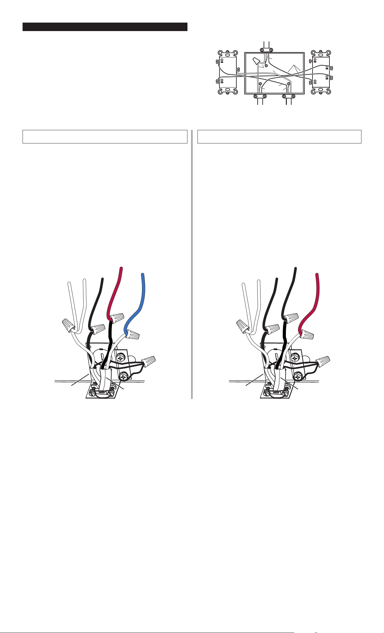
Install 2 included rocker switches at a convenient place for the
user. Feed the switch box with 120 VAC house wiring and use two
14/2 cable to wire it to the range hood (see diagram at right).
Insert both 14/2 cable coming from switches in the hood through
an UL approved wire clamp. With a short ground wire (not
provided), connect all ground wires together as shown below.
Connect the other end of the short ground wire to the GREEN
ground screw.
Connect WHITE wire from no. 2 14/2 cable to WHITE wire from
blower connector and WHITE wire coming from light socket.
Connect BLACK wire from no. 2 14/2 cable to BLACK wire cut
from light switch.
Connect BLACK wire from no. 1 14/2 cable to RED wire cut from
motor switch.
Connect WHITE wire from no. 1 14/2 cable to BLUE wire cut
from motor switch.
NO. 1
14/2 CABLE
TO HOOD
BLACK
GROUND
On/Off
light switch
On/Off
motor switch
NO. 2
14/2 CABLE
TO HOOD
120 VAC
LINE IN
Motor speed
selection switch
COM
GROUND
WHITE
BLACK
NO. 1
14/2 CABLE
NO. 2
14/2 CABLE
1
2
4
3
5
NOTE: Use appropriate wire nuts for all connections.
Range hood series: BUEZ0, BUEZ1, BUEZ2, BU2, BXT1,
40000, F40000, 41000, 42000, NU2 and RL62000.
Range hood series: BUEZ3 and 43000.
Insert both 14/2 cable coming from switches in the hood through
an UL approved wire clamp.With a short ground wire (not
provided), connect all ground wires together as shown below.
Connect the other end of the short ground wire to the GREEN
ground screw.
Connect WHITE wire from no. 2 14/2 cable to WHITE wire from
blower connector and WHITE wire coming from light socket.
Connect BLACK wire from no. 2 14/2 cable to BLACK (or BLUE)
wire cut from light switch.
Connect BLACK wire from no. 1 14/2 cable to BLACK wire cut
from motor switch.
Connect WHITE wire from no. 1 14/2 cable to RED wire cut from
motor switch.
NOTE: Use appropriate wire nuts for all connections.
NO. 1
14/2 CABLE
NO. 2
14/2 CABLE
1
2
4
3
5
120 VAC POWER CABLE ENTERING THE SWITCH BOX
Loading ...
Loading ...
Loading ...