)
SEARS
owners
manual
Model No.
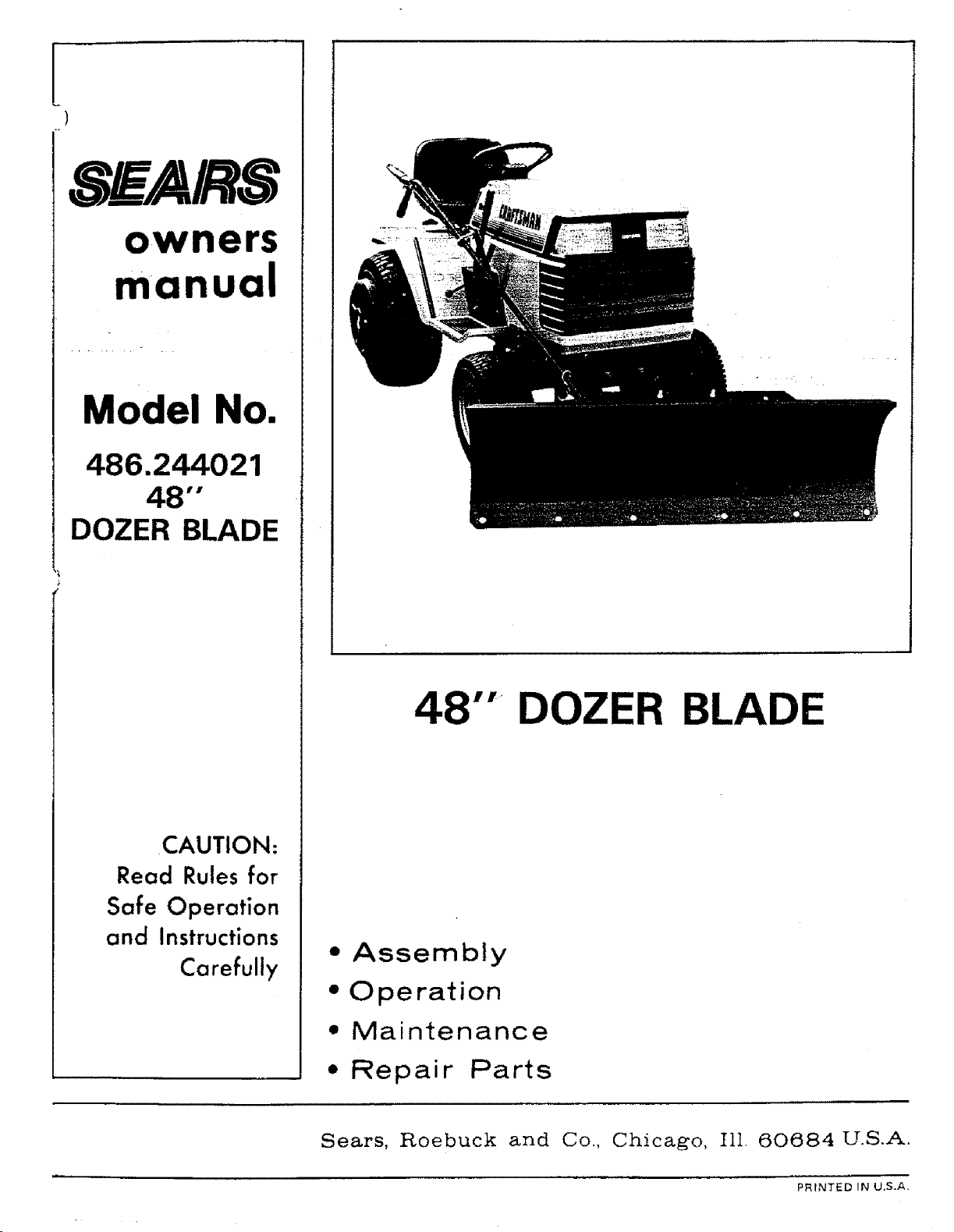
486.244021
48""
DOZER BLADE
CAUTION:
Read Rules for
Safe Operation
and Instructions
Carefully
48 "'_DOZER B
• Assembly
• Operation
• Maintenance
• Repair Parts
Sears, Roebuck and Co., Chicago, Ill 60684 U.S.A.
PRINTED IN U.S.A.
RULES FOR SAFE OPERATIONS
Remember, any power equipment can cause injury if operated improperly or if the user does not understand how to operate
the equipment.
LOOK FOR THIS SYMBOL TO POINT OUT
IMPORTANT SAFETY PRECAUTIONS. IT
MEANS--- ATTENT:fONf BECOME ALERT!
YOUR SAFETY IS INVOLVED.
Exercise caution at all times, when using power equipment.
1. Read the tractor and dozer blade owners manuals and know how to operate your tractor, before using tractor with the
dozer blade attachment.
2. Never operate tractor and dozer blade without wearing proper clothing suited to weather conditions and operation of
controls.
3. Never allow children to operate tractor and dozer blade, and do not allow adults to operate without proper instructions.
4. Always begin with transmission in first (low) gear and engine at tow speed, and gradually increase speed as required.
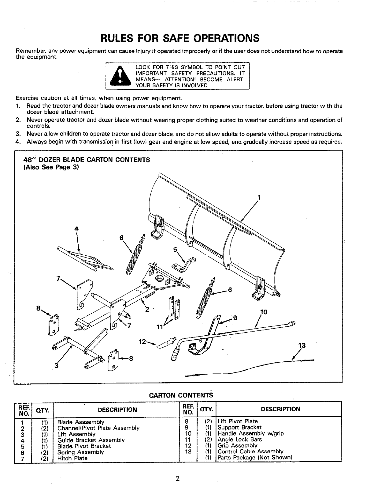
48" DOZER BLADE CARTON CONTENTS
(Also See Page 3)
4
13
CARTON CONTENTS
REF. QTY. DESCRIPTION RER QTY. DESCRIPTION
NO. NO.
1 (1) Blade Asssembly 8 (2) Lift Pivot Plate
2 (2) Channel/Pivot Plate Assembly 9 (1) Support Bracket
3 (1) Lift Assembly 10 (1) Handle Assembly w/grip
4 (1) Guide Bracket Assembly 11 (2) Angle Lock Bars
5 (I) Blade. Pivot Bracket 12 (1) Grip Assembly
6 (2) Spring Assembly 13 (1) Control Cable Assembly
7 (2) Hitch Plate (1) Parts Package (Not Shown)
2
A B C D_ jE
s AC
_,_R _ _R _ K
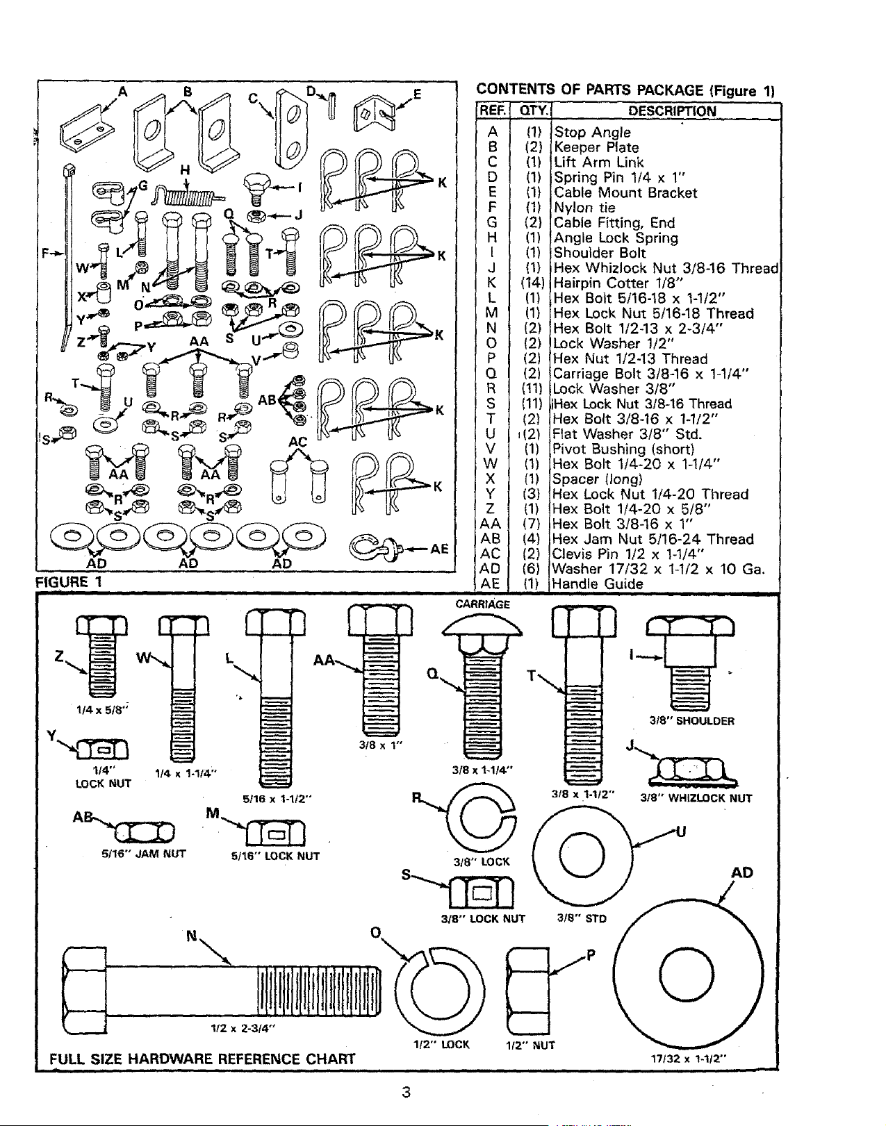
FIGURE 1
E
z
1/4 x 5/8";
1/4"'
LOCK NUT
1/4 x 1-114"'
5/16" JAM NUT
L
*l
5/16 x I-1/2"'
5/16" LOCK NUT
1f2 x 2-3/4"
FULL SIZE HARDWARE REFERENCE CHART
CONTENTS OF PARTS PACKAGE (Figure 1)
IREF.I QTY.J DESCRIPTION
IAI _1)istop Angle ..........." "
I B I (2) j Keeper Plate
} C I (1) ILift Arm Link ,
1 D I (1) ISpring Pin 1/4 x 1'
I E I (1} tCable Mount Bracket
I F I (t)INylon tie
[ G J (2)[Cable Fitting, End
I H I (1) IAngle Lock Spring
I I t (1))Shoulder Bolt
I J I (1) tHex Whizlock Nut 3/8-16 Thread
I K I (14)IHairpin Cotter 1/8" ,,
I L I (1) tHex Bott 5/16-18 x t-1/2
t M I (1) IHex Lock Nut 5/16-18 Thread
I N i (2) IHex Bolt 1/2-13 x 2-3/4
I O I (2) ILock Washer 1/2"
[ P I (2) _Hex Nut 1/2-13 Thread ,,
I Q ! (2) ICarriage Bolt 3/8,_16 x 1-1/4
i R I (11) ILock Washer 3/8
I S I (11) IlHex Lock Nut 3t8-!6 Thread
T t (21 _Hex Bolt 3/8-16,x 1-1/2'
t U / _(2) tFIat Washer 3/8 Std.
t V I (1) IPivot Bushing (short) ,
I W t (1) IHex Bolt 1/4-20 x 1-1/4'
I X I (1)/Spacer (long)
/ Y [ (3) [Hex Lock Nut 1/4-20 Thread
I Z / (1) IHex Bolt 114-20 x 5!8'
/AA | (7) /Hex Bolt 3/8-16 x 1
I AB / (4) IHex Jam Nut 5/16-24 Thread
/AC | (2) /Clevis Pin 1/2 x !-t/4"
IAD / (6) IWasher 17/32 x 1-1/2 x 10 Ga.
AE (1) Handle Guide
CARRIAGE
3f8 x I"
318 x 1-1/4"
318" LOCK
318" LOCK NUT
3/8 x 1-1/2""
3t8"' STD
1t2" LOCK
_._P
1/2" NUT
3t8" SHOULDER
3t8 '° WHIZLOCK NUT
AD
O
17/32 x 1-1f2"'
u i u
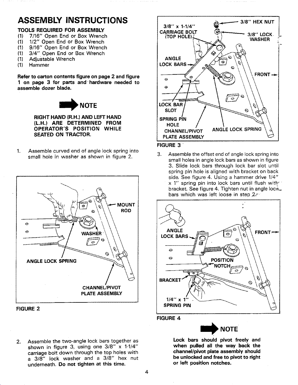
ASSEMBLY INSTRUCTIONS
TOOLS REQUIRED FOR ASSEMBLY
(1) 7/16" Open End or Box Wrench
(1) 1/2" Open End or Box Wrench
(1) 9/16" Open End or Box Wrench
(1) 3/4" Open End or Box Wrench
(1) Adjustable Wrench
(1) Hammer
Refer to carton contents figure on page 2 and figure
1 on page 3 for parts and'hardware needed to
assemble dozer blade,
RIGHT HAND (R.H,} AND LEFT HAND
(LH.) ARE DETERMINED FROM
OPERATOR'S POSITION WHILE
SEATED ON TRACTOR.
1, Assemble curved end of angle lock spring into
small hole in washer as shown in figure 2,
MOUNT
ROD
e
ANGLE LOCK SPRING
CHANNEL/PIVOT
PLATE ASSEMBLY
FIGURE 2
, Assemble the two-angle lock bars together as
shown in figure 3, using one 3/8" x 1-1/4"
carriage bolt down through the top holes with
a 3/8" lock washer and a 3/8" hex nut
underneath. Do not tighten at this time.
I
e'*'-"-_ 3/8" HEX NUT I3/8"
x 1-1t4"
CARRIAGE BOLT 3/8" LOCK. I
(TOP _ WASHER *_
ANGLE
LOCK
FRONT -_
LOCK BAR
SLOT
SPRING PiN
HOLE
CHANNEL/PIVOT
PLATE ASSEMBLY
ANGLE LOCK SPRING
FIGURE 3
,
Assemble the offset end of angle lock spring into
small holes in angle lock bars as shown in figure
3. Slide lock bars through lock bar slot until
spring pin hole is aligned with bracket on back
side. See figure 4, Using a hammer drive 1/4"
x 1" spring pin into lock bars until flush wit_
bracket. See figure 4. Tighten nut in angle loc¢_
bars which was left loose in step 2,.--
ANGLE
LOCKe_ BARS_,
FIGURE 4
NOTE
Lock bars should pivot freely and
when pulled all the way back the
channellpivot plate assembly should
be unlocked and free to pivot to right
or left position notches.
.
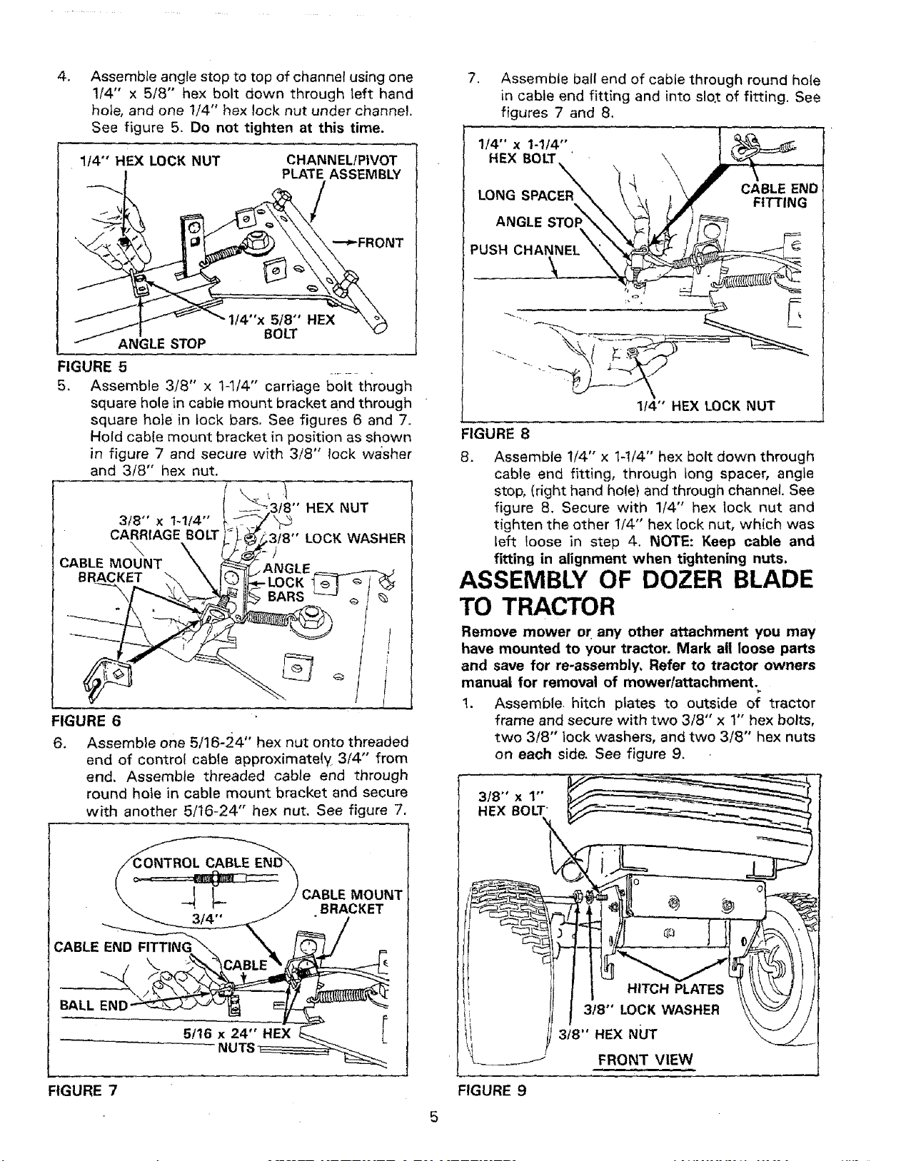
Assemble angle stop to top of channel using one
1/4" x 5/8" hex bolt down through left hand
hole, and one 1/4" hex lock nut under channel.
See figure 5. Do not tighten at this time.
114"' HEX LOCK NUT
CHANNEL!PIVOT
PLATE ASSEMBLY
I/4"x 5/8" HEX
BOLT
ANGLE STOP
FIGURE 5
5.
3/8" x 1-1t4"
CARRIAGE BOLT
\
CABLE MOUNT
BRACKET
Assemble 3/8" x 1-l/4" carriage bolt through
square hole in cable mount bracket and through
square hole in lock bars. See figures 6 and 7.
Hold cable mount bracket in position as shown
in figure 7 and secure with 3/8" lock wa'sher
and 3/8" hex nut.
,1
f8" HEX NUT
3tB" LOCK WASHER
FIGURE 6
6. Assemble one 5/16-24" hex nut onto threaded
end of control cable approximately 3/4"' from
end. Assemble threaded cable end through
round hole in cable mount bracket and secure
with another 5/16-24" hex nut. See figure 7.
MOUNT
•BRACKET
CABLE END
BALL EN[
FIGURE 7
7. Assemble ball end of cable through round hote
in cable end fitting and into slo,t of fitting. See
figures 7 and 8.
1/4" x I-1/4'"
HEX BOLT
CABLE END
LONG FITTING
ANGLE STOF
PUSH CHANNEL
1t4" HEX LOCK NUT
FIGURE 8
8. Assemble !/4" x 1-1/4" hex bolt down through
cable end fitting, through tong spacer, angle
stop, (right hand hole) and through channel. See
figure 8. Secure with 1/4" hex lock nut and
tighten the other !/4"' hex lock nut, which was
left loose in step 4. NOTE: Keep cable and
fitting in alignment when tightening nuts.
ASSEMBLY OF DOZER BLADE
TO TRACTOR
Remove mower or any other attachment you may
have mounted to your tractor. Mark all loose parts
and save for re-assembly, Refer to tractor owners
manual for removal of mower/attachment.
1. Assemble. hitch plates to outside of tractor
frame and secure with two 3/8" x 1" hex bolts,
two 3/8" lock washers, and two 3/8" hex nuts
on each side. See figure 9,
318°' x 1"'
HEX BOLT
J
FIGURE 9
5
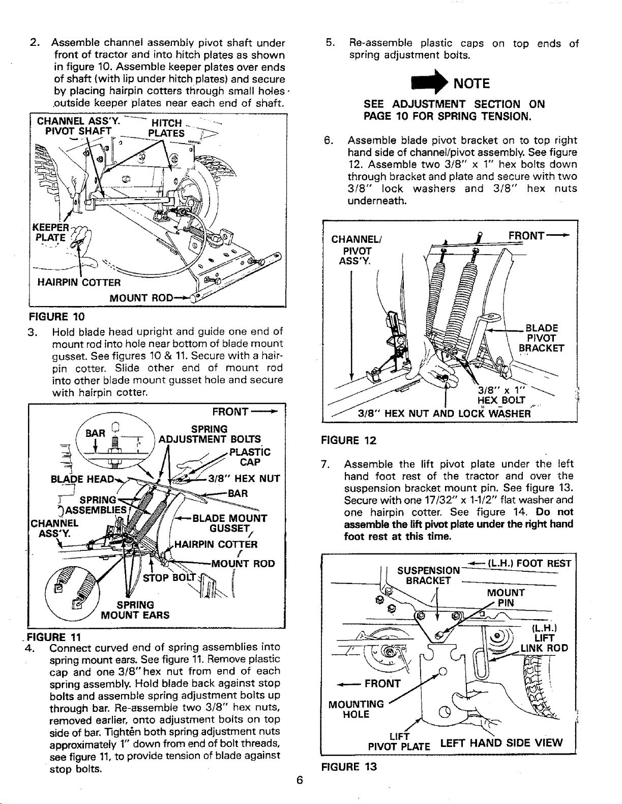
2_
Assemble channel assembly pivot shaft under
front of tractor and into hitch plates as shown
in figure 10. Assemble keeper plates over ends
of shaft (with lip under hitch plates) and secure
by placing hairpin cotters through small holes-
.outside keeper plates near each end of shaft.
CHANNEL ASS'Y. -_-_ HITCH _ r
PIVOT SHAFT __ PLATES _ J
KEEPER
HAIRPIN COTTER
MOUNT
FIGURE 10
3. Hoid blade head upright and guide one end of
mount rod into hole near bottom of blade mount
gusset. See figures 10 & !1. Secure with a hair-
pin cotter. Slide other end of mount rod
into other blade mount gusset hole and secure
with hairpin cotter.
SPRING
ADJUSTMENT BOLTS
BLADE
CAP
HEX NUT
CHANNEL
ASS'Y.
MOUNT
GUSSET/
HAIRPIN COTTER
[
ROD
SPRING
MOUNT EARS
. FIGURE 11
4. Connect curved end of spring assemblies into
spring mount ears. See figure 1t. Remove plastic
cap and one 3/8"hex nut from end of each
spring assembly. Hold blade back against stop
bolts and assemble spring adjustment bolts up
through bar. Re-assemble two 3/8" hex nuts,
removed earlier, onto adjustment bolts on top
side of bar. "13ght6n both spring adjustment nuts
approximately 1" down from end of bolt threads,
see figure 11,to provide tension of blade against
stop bolts.
.
.
Re-assemble plastic caps on top ends of
spring adjustment bolts.
NOTE
SEE ADJUSTMENT SECTION ON
PAGE 10 FOR SPRING TENSION.
Assemble blade pivot bracket on to top right
hand side of channel!pivot assembly. See figure
12. Assemble two 3/8" x 1" hex bolts down
through bracket and plate and secure with two
3/8" lock washers and 3/8" hex nuts
underneath.
CHANNEL/
PIVOT
ASS'Y,
BLADE
PIVOT
BRACKET
318" x 1"
HEX BOLT
3/8" HEX NUT AND LOCI{ WASHER....
FIGURE 12
,
Assemble the lift pivot plate under the left
hand foot rest of the tractor and over the
suspension bracket mount pin. See figure 13.
Secure with one 17/32" x 1-1/2" flat washer and
one hairpin cotter. See figure 14. Do not
assemble the lift pivot plate under the right hand
foot rest at this time.
LIFT
PIVOT PLATE LEFT HAND SIDE VIEW
FIGURE 13
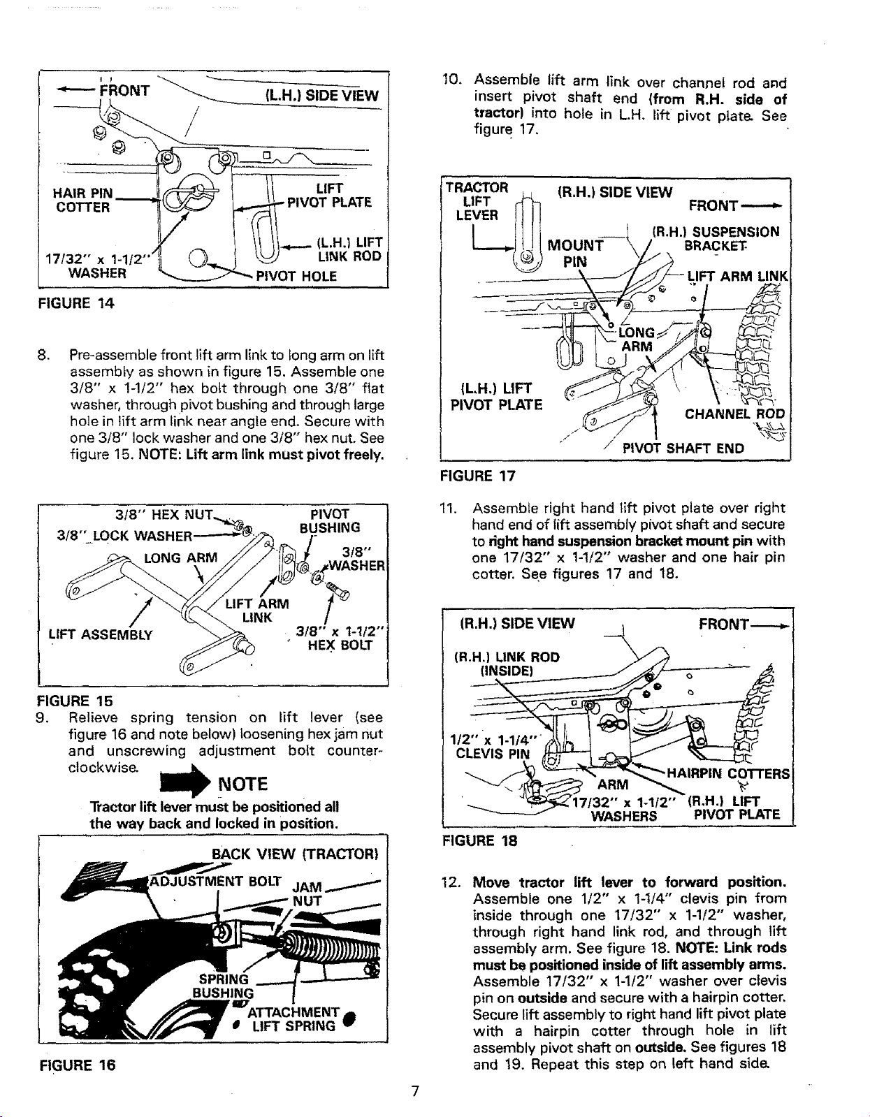
""---- FRONT
(LH.) SIDE VIEW
HAIR PIN
COTTER
17/32" x 1-1
WASHER
-I/ LIFT¸
_ PIVOT PLATE
// /I"_-'- (L.H.) LIFT
LtNK ROD
PIVOT HOLE
FIGURE 14
,
Pre-assemble front lift arm link to long arm on lift
assembly as shown {n figure 15. Assemble one
3/8" x 1-!/2" hex bolt through one 3/8" flat
washer, through pivot bushing and through large
hole in lift arm link near angle end. Secure with
one 3/8" lock washer and one 3/8" hex nut, See
figure 15. NOTE: Lift arm link must pivot freely.
3f8" HEX PIVOT
BUSHING
3/8"" LOCK WASHER
LONG ARM 3/8"
10.
Assemble lift arm link over channel rod and
insert pivot shaft end (from R.H. side of
tractor) into hole in L.H, lift pivot plate- See
figure 17.
TRACTOR
(R.H.) SIDE VIEW
FRONT'-"-_
(R.H.) SUSPENSION
MOUNT BRACKET
PIN
_RM LINK
(LH.) LIFT i
PIVOT PLATE
CHANNEL ROD
.,_
/ / PIVOT SHAFT END
FIGURE 17
11.
Assemble right hand Iift pivot plate over right
hand end of tift assembly pivot shaft and secure
to right hand suspension bracket mount pin with
one 17/32" x 1-1/2" washer and one hair pin
cotter. See figures 17 and 18.
LIFT ASSEMBLY
HEX BOLT
FIGURE 15
9. Relieve spring tension on lift lever {see
figure 16 and note below) !oosening hex jam nut
and unscrewing adjustment bo{t counter-
clockwise.
NOTE
Tractor lift lever must be positioned all
the way back and locked in position.
BACK VIEW (TRACTOR)
NUT
_TTACHMENT j
0 LIFT SPRING w
FIGURE 16
7
(R.H.) SIDE VIEW _ FRONT----.-
(R.H.) LINK ROD \_/-" "
_ U
__r"'_ HAIRpl_rT ERs
'__--_17132 x 1-1/2 (R.H.) LIFT
WASHERS PIVOT PLATE
FIGURE 18
12.
Move tractor lift lever to forward position.
Assemble one 1/2" x 1-1/4" clevis pin from
inside through one 17/32" x 1-1/2" washer,
through right hand link rod, and through lift
assembly arm. See figure 18. NOTE: Link rods
must be positioned inside of lift assembly arms.
Assemble 17/32" x 1-1/2" washer over clevis
pin on outside and secure with a hairpin cotter,
Secure lift assembly to right hand lift pivot plate
with a hairpin cotter through hole in lift
assembly pivot shaft on outside, See figures 18
and 19. Repeat this step on left hand side-
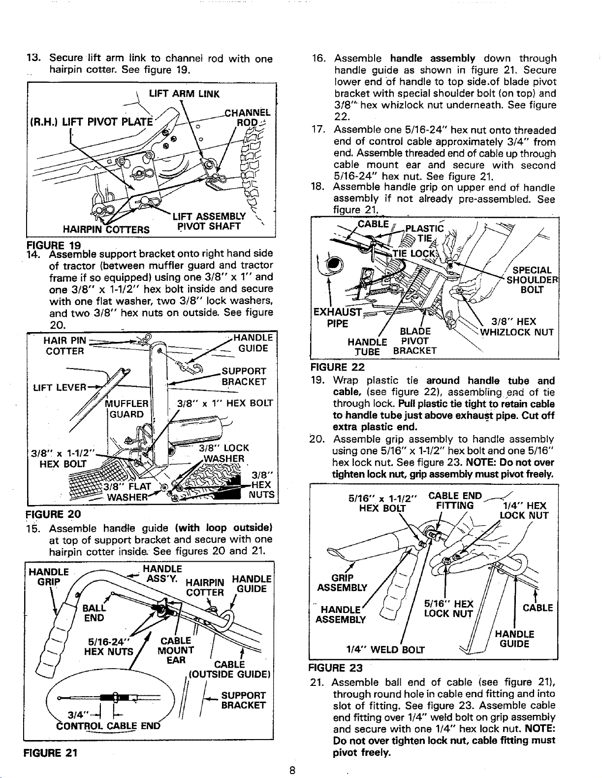
13, Secure lift arm link to channel rod with one
hairpin cotter. See figure t9.
_..__\LIFT ARM LINK
• -IANNEL
(R.H.) LIFT PIVOT ROD:_
ASSEMBLY
HAIRPIN COTTERS pIVOT SHAFT
FIGURE 19
14. Assemble support bracket onto right hand side
of tractor (between muffler guard and tractor
frame if so equipped) using one 3/8" x 1" and
one 3/8" x 1-1/2" hex bolt inside and secure
with one flat washer, two 3/8" lock washers,
and two 3/8" hex nuts on outside. See figure
20,
i
HAIR PIN
COTTER
LIFT
3t8" x
HEX BOLT
FLAT
FIGURE 20
15, Assemble handle guide (with loop outside}
at top of support bracket and secure with one
hairpin cotter inside-See figures 20 and 21.
HANDLE
ASS'Y.
3,,-1 I--
CONTROL CABLE END
HAIRPIN HANDLE
COTTER GUIDE
FIGURE 21
16. Assemble handle assembly down through
handle guide as shown in figure 21, Secure
lower end +ofhandle to top side,of blade pivot
bracket with special shoulder bolt (on top) and
318 '" hex whizlock nut underneath. See figure
22.
17. Assemble one 5/16-24" hex nut onto threaded
end of control cable approximately 314" from
end. Assemble threaded end of cable up through
cable mount ear and secure with second
5/16-24" hex nut. See figure 21.
18. Assemble handle grip on upper end of handle
assembly if not already pre-assembled. See
figure 21.
l !
EXHAUST
PIPE
BLADE
HANDLE PIVOT
TUBE BRACKET
SPECIAL
SHOULDER
BOLT
3/8" HEX
;K NUT
FIGURE 22
19. Wrap plastic tie around handle tube and
cable, (see figure 22), assembling e_d of tie
through lock. Pull plastic tie tight to retain cable
to handle tube just above exhaust pipe. Cut off
extra plastic end.
20. Assemble grip assembly to handte assembly
using one 5/16" x 1-1/2" hex bolt and one 5/16"
hex lock nut, See figure 23. NOTE: Do not over
tighten lock nut, grip assembly must pivot freely.
5/16" x 1-1/2" CABLE END_-_
REX BOLT FITTING 114" REX
LOCK NUT
/
GRIP
ASSEMBLY
CABLE
ASSEMBLY
/ HANDLE
GUIDE
1/4" WELD BOLT
FIGURE 23
21. Assemble ball end of cable (see figure 21),
through round hole in cable end fitting and into
slot of fitting. See figure 23. Assemble cable
end fitting over 1/4'" weld bolt on grip assembly
and secure with one 1/4" hex lock nut, NOTE:
Do not over tighten lock nut, cable fitting must
pivot freely.
(R.H.) HITCH PLATE
_:IL,H.) HITCH PLATE
SHAFT END
/_ GUIDE
BRACKET CHANNEL
ASSEMBLY ASSEMBLY
FIGURE 24
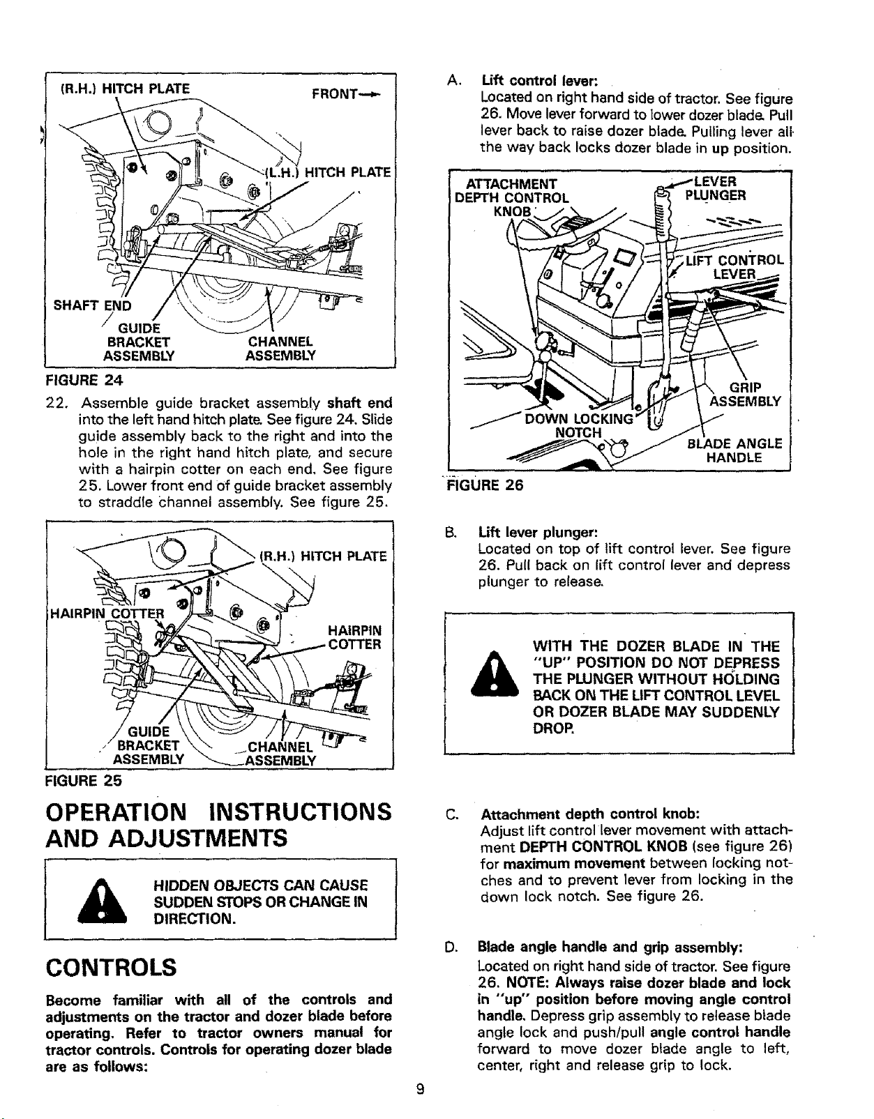
22.
Assemble guide bracket assembly shaft end
into the left hand hitch plate` See figure 24. Slide
guide assembly back to the right and into the
hole in the right hand hitch plate, and secure
with a hairpin cotter on each end, See figure
25. Lower front end of guide bracket assembly
to straddle Channel assembly. See figure 25.
(R,H.) HITCH PLATE
\
_AIRPIN COTTER
HAIRPIN
//BRACKET
ASSEMBLY
FIGURE 25
jCHANNEL
_ASSEMBLY
OPERATION
AND ADJUSTMENTS
INSTRUCTIONS
HIDDEN OBJECTS CAN CAUSE
SUDDEN STOPS OR CHANGE IN
DIRECTION.
CONTROLS
Become familiar with all of the controls and
adjustments on the tractor and dozer blade before
operating. Refer to tractor owners manual for
tractor controls. Controls for operating dozer blade
are as follows:
A, Lift control lever:
Located on right hand side of tractor. See figure
26. Move lever forward to lower dozer blad& Pull
lever back to raise dozer blade, Pulling lever all.
the way back locks dozer blade in up position.
ATTACHMENT
DEPTH CONTROL
KNOB
GRIP
FIGURE 26
BLADE ANGLE
HANDLE
B°
Lift lever plunger:
Located on top of lift control lever. See figure
26. Pull back on lift control lever and depress
plunger to release.
&
WITH THE DOZER BLADE IN THE
"UP" POSITION DO NOT DEPRESS
THE PWNGER WITHOUT H()LDING
BACK ON THE LIFT CONTROL LEVEL
OR DOZER BLADE MAY SUDDENLY
DROP.
C.
Attachment depth control knob:
Adjust lift control lever movement with attach-
ment DEPTH CONTROL KNOB (see figure 26)
for maximum movement between locking not-
ches and to prevent lever from locking in the
down lock notch. See figure 26.
D.
Blade angle handle and grip assembly:
Located on right hand side of tractor. See figure
26. NOTE: Always raise dozer blade and lock
in "up" position before moving angle control
handle, Depress grip assembly to release blade
angle lock and push/pull angle control handle
forward to move dozer blade angle to left,
center, right and release grip to lock.
ADJUSTMENTS
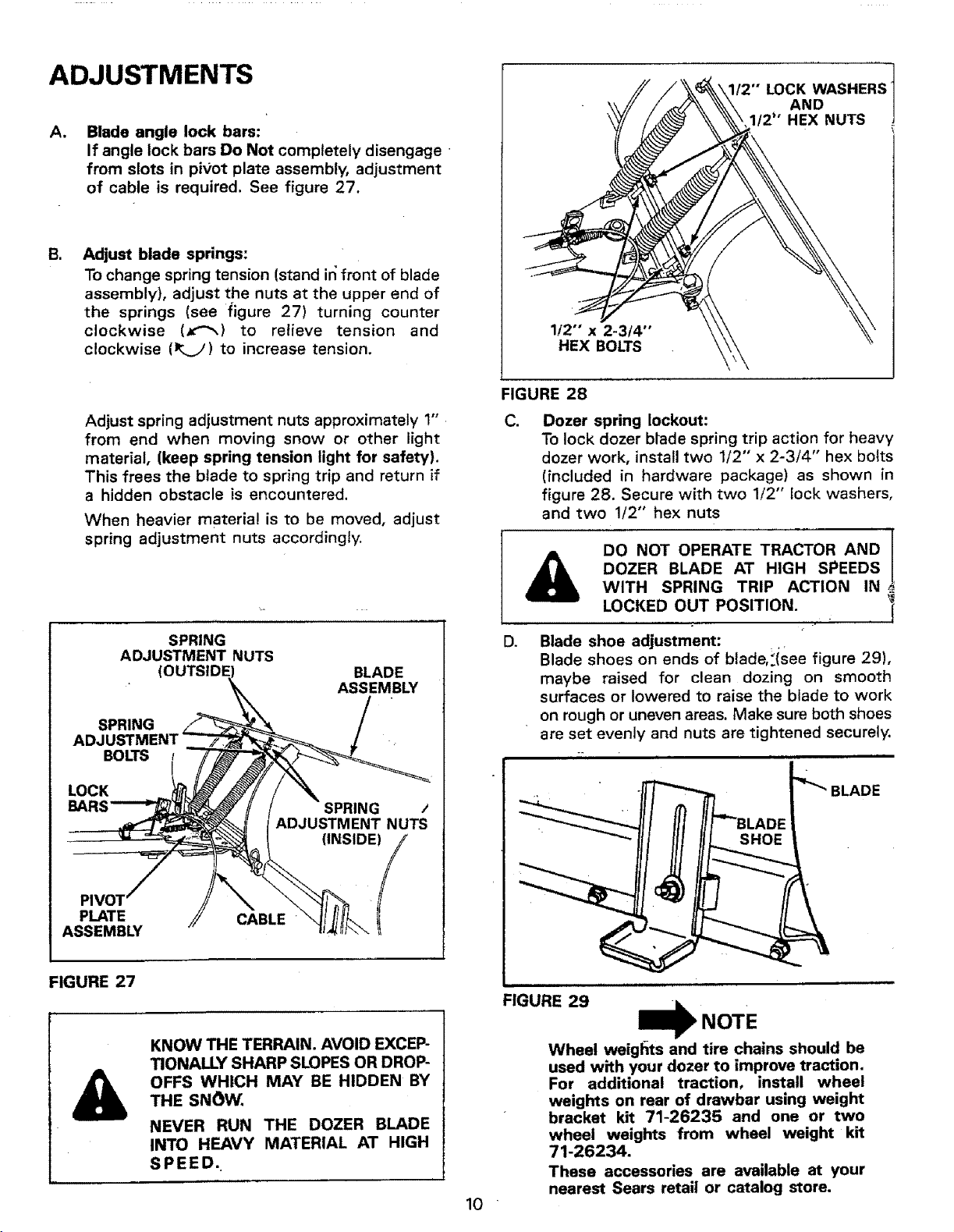
AI
Blade angle lock bars:
If angle lock bars Do Not completely disengage -
from slots in pivot plate assembly, adjustment
of cable is required. See figure 27.
B,
Adjust blade springs:
To change spring tension (stand in front of blade
assembly), adjust the nuts at the upper end of
the springs (see figure 27) turning counter
clockwise (x'_) to relieve tension and
clockwise (_) to increase tension.
1/2" x 2-3/4"
HEX BOLTS
LOCK WASHERS
AND
1/2" HEX NUTS
Adjust spring adjustment nuts approximately 1"
from end when moving snow or other light
material, (keep spring tension light for safety).
This frees the blade to spring trip and return if
a hidden obstacle is encountered.
When heavier material is to be moved, adjust
spring adjustment nuts accordingly.
SPRING
ADJUSTMENT NUTS
( BLADE
ASSEMBLY
SPRING
BOLTS
LOCK
SPRING /
ADJUSTMENT NUTS
(INSIDE)
PIVO1 lPLATE ,/_' CABLE
ASSEMBLY
FIGURE 27
&
KNOW THE TERRAIN. AVOID EXCEP-
TIONALLY SHARP SLOPES OR DROP-
OFFS WHICH MAY BE HIDDEN BY
THE SNOW,
NEVER RUN THE DOZER BLADE
INTO HEAVY MATERIAL AT HIGH
SPEED.
FIGURE 28
&
C. Dozer spring lockout:
To lock dozer btade spring trip action for heavy
dozer work, install two 1/2" x 2-3/4" hex bolts
(included in hardware package) as shown in
figure 28. Secure with two 1/2" lock washers,
and two 1/2" hex nuts
DO NOT OPERATE TRACTOR AND /
J
DOZER BLADE AT HIGH SPEEDS
WITH SPRING TRIP ACTION IN.
LOCKED OUT POSITION. 'l
|
D. Blade shoe adjustment:
Blade shoes on ends of blade,!isee figure 29),
maybe raised for clean dozing on smooth
surfaces or lowered to raise the blade to work
on rough or uneven areas. Make sure both shoes
are set evenly and nuts are tightened securely.
BLADE
10
FIGURE 29
NOTE
--'IF
Wheel weig[_ts and tire chains should be
used with your dozer to improve traction.
For additional traction, install wheel
weights on rear of drawbar using weight
bracket kit 71-26235 and one or two
wheel weights from wheel weight kit
71-26234.
These accessories are available at your
nearest Sears retail or catalog store.
OPERATION
&
INSPECT THE AREA TO BEWORKED
CAREFULLY BEFORE OPERATING
THE DOZER BLADE, AVOID PIPES,
ROOTS, CURBS OR OTHER HEAVY
OBSTRUCTIONS.
1. Prepare the tractor engine for cold weather
use following instructions furnished with tractor.
2, Always begin with transmission in first (low)
gear and engine at slow speed and gradually
increase speed as required.
. If blade is stored in heated area, allow tractor
and blade to adjust to outdoor temperature
before operating to reduce icing on the metal
surfaces.
ALWAYS LOWER BLADE TO
GROUND BEFORE LEAVING
TRACTOR.
TO REMOVE DOZER BLADE
FROM TRACTOR
1. Lower blade to ground with blade in the center
(straight) position.
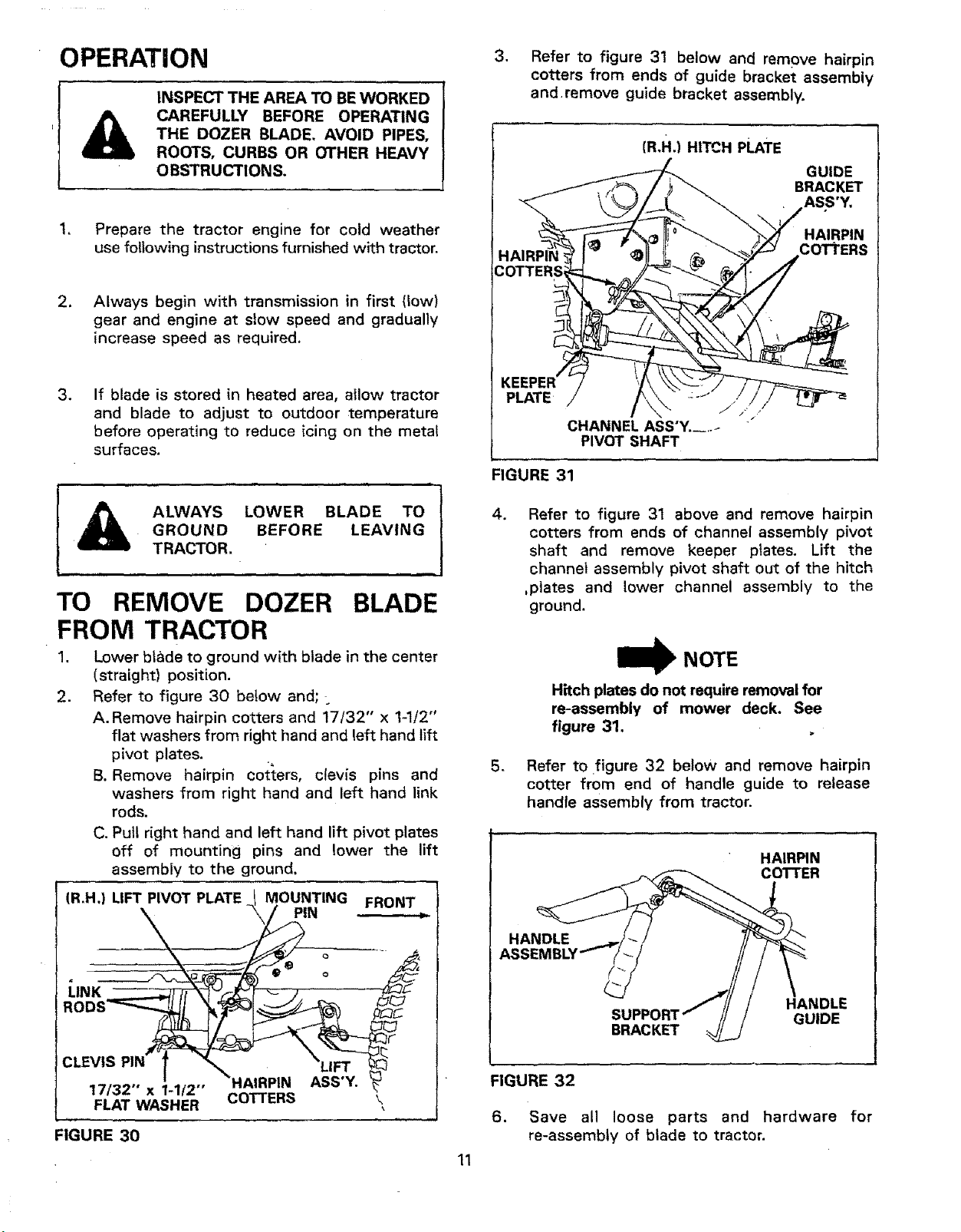
2. Refer to figure 30 be{ow and;.
A. Remove hairpin cotters and 17/32" x 1-1/2"
flat washers from right hand and left hand lift
pivot plates.
B. Remove hairpin cotters, clevis pins and
washers from right hand and left hand link
rods.
C. Pull right hand and left hand lift pivot plates
off of mounting pins and lower the lift
assembly to the ground.
(R,H.) UFT PIVOT PLATE I MOUNTING FRONT
\\ Y4'" '
o
ROOSt/
CO ERS \
FIGURE 30
11
3. Refer to figure 31 below and remove hairpin
cotters from ends of guide bracket assembly
and.remove guide bracket assembly.
HAIRPIN'
COTTERSl
(R.H.) HITCH PLATE
GUIDE
BRACKET
ASS'Y,
HAIRPIN
cOTtERS
PLATE
,4 E,J
CHANNEL ASS'Y. ....
PIVOT SHAFT
FIGURE 31
.
Refer to figure 31 above and remove hairpin
cotters from ends of channel assembly pivot
shaft and remove keeper plates. Lift the
channel assembly pivot shaft out of the hitch
,plates and lower channel assembly to the
ground.
W NOTE
Hitch plates do not require removal for
re-assembly of mower deck. See
figure 31,
5. Refer tO figure 32 below and remove hairpin
cotter from end of handle guide to release
handle assembly from tractor.
HAIRPIN
COTTER
HANDLE
BRACKET
HANDLE
GUIDE
FIGURE 32
6. Save all loose parts and hardware for
re-assembly of blade to tractor.
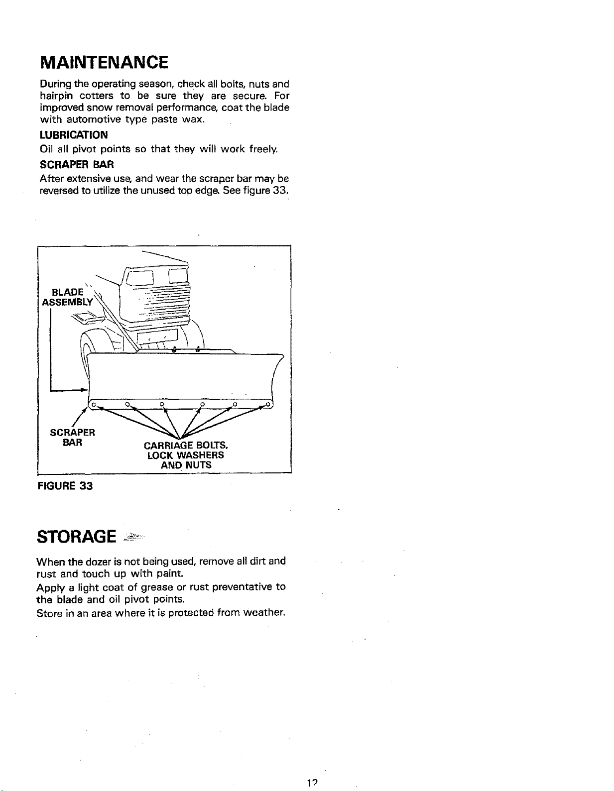
MAINTENANCE
During the operating season, check all bolts, nuts and
hairpin cotters to be sure they are secure. For
improved snow removal performance, coat the blade
with automotive type paste wax.
LUBRICATION
Oil all pivot points so that they will work freely.
SCRAPER BAR
After extensive use, and wear the scraper bar may be
reversed to utilize the unused top edge, See figure 33.
BLADE \" _ l "-_
ASSEMBLY\\I -::_
- f
SCRAPER
BAR CARRIAGE BOLTS,
LOCK WASHERS
AND NUTS
FIGURE 33
STORAGE ,_'....
When the dozer is not being used, remove all dirt and
rust and touch up with paint.
Apply a light coat of grease or rust preventative to
the blade and oil pivot points.
Store in an area where it is protected from weather.
19
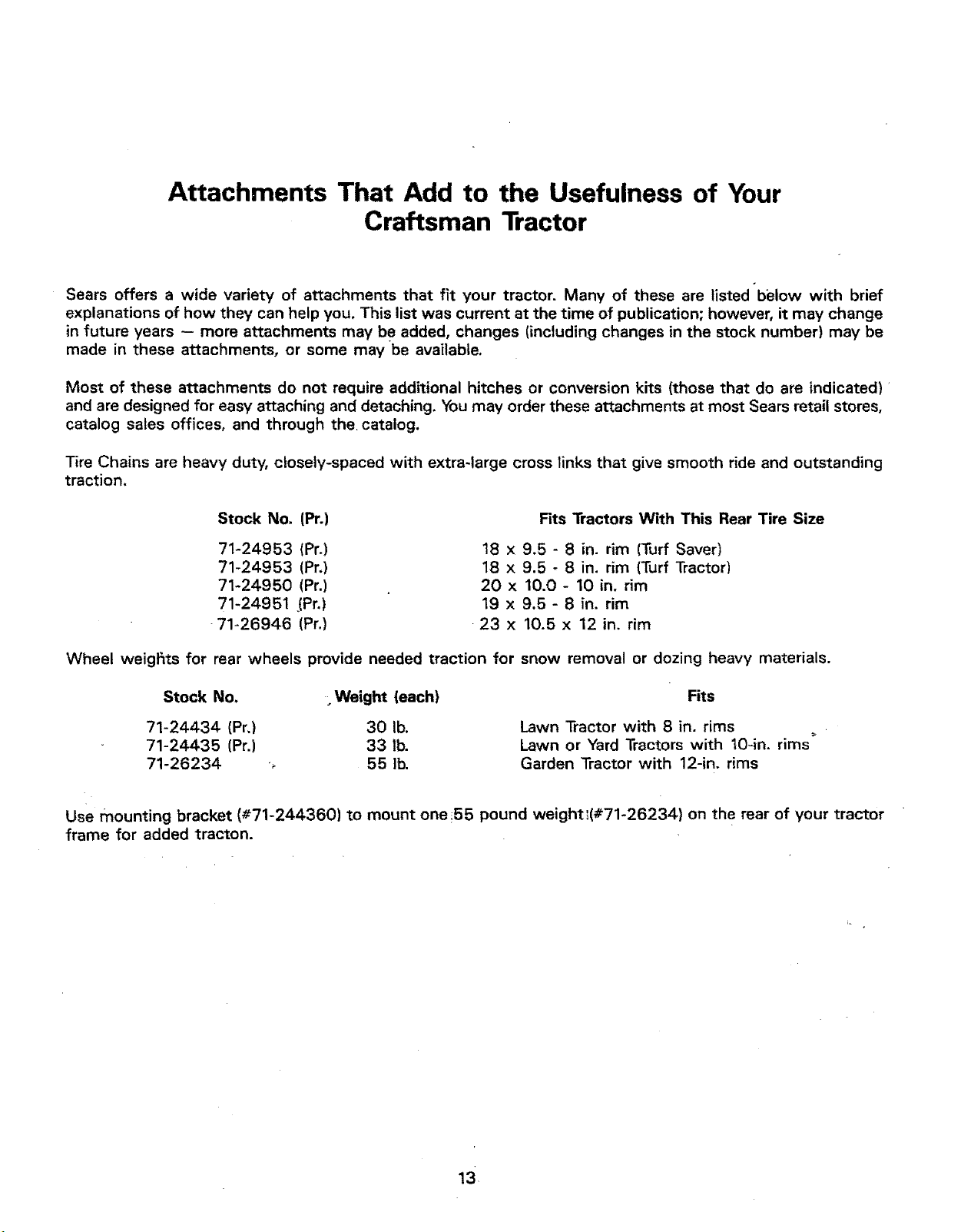
Attachments That Add to the Usefulness of Your
Craftsman Tractor
Sears offers a wide variety of attachments that fit your tractor. Many of these are listed below with brief
explanations of how they can help you. This list was current at the time of publication; however, it may change
in future years -- more attachments may be added, changes (including changes in the stock number) may be
made in these attachments, or some may be available.
Most of these attachments do not require additional hitches or conversion kits (those that do are indicated)
and are designed for easy attaching and detaching. You may order these attachments at most Sears retail stores,
catalog sales offices, and through the, catalog.
Tire Chains are heavy duty, closely-spaced with extra-large cross links that give smooth ride and outstanding
traction.
Stock No. (Pr.)
71-24953 (Pr.)
71-24953 (Pr.)
71-24950 (Pr.)
71-24951 ,(Pr.)
71-26946 (Pr.)
Fits Tractors With This Rear Tire Size
18 x 9.5 - 8 in. rim (Tuff Saver)
18 x 9.5 - 8 in. rim (Turf Tractor)
20 x 10.0 - 10 in. rim
19 x 9.5 - 8 in, rim
23 x 10.5 x 12 in. rim
Wheel weigfits for rear wheels provide needed traction for snow removal or dozing heavy materials.
Stock No.
Weight (each)
71-24434 (Pr,) 30 lb.
71-24435 (Pr.) 33 lb.
71-26234 _ 55 lb.
Fits
Lawn Tractor with 8 in. rims
Lawn or Yard Tractors with 10gn. rims
Garden Tractor with 12-in. rims
Use mounting bracket (#71-244360) to mount one_55 pound weight_(#71-26234) on the rear of your tractor
frame for added tracton.
13
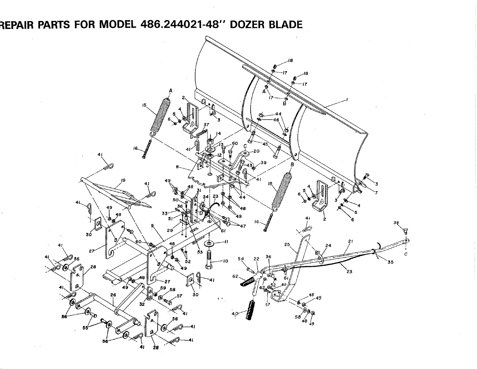
_EPAIR PARTS FOR MODEL 486.244021-48" DOZER BLADE
49
22 36
24
6
2!
32
41
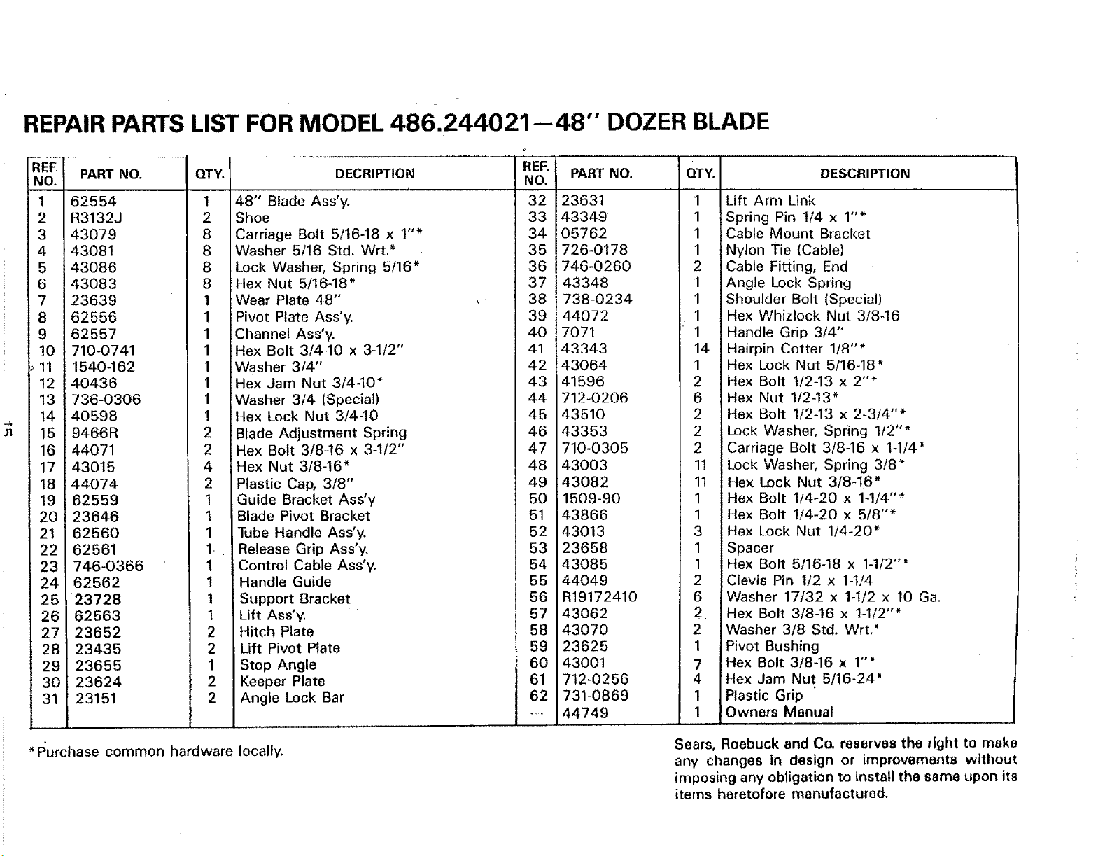
REPAIR PARTS LIST FOR MODEL 486.244021--48" DOZER BLADE
REE
NO. PART NO.
1 62554
2 R3132J
3 43079
4 43081
65 43086
43083
7 23639
8 62556
9 62557
10 710-0741
i_11 1540-162
12 40436
13 736-0306
14 40598
15 9466R
16 44071
17 43015
18 44074
19 62559
20 23646
21 62560
22 62561
23 746-0366
24 62562
25 23728
26 62563
27 23652
28 23435
29 23655
30 23624
31 23151
QTY. DECRIPTION
1 48" Blade Ass'y.
2 Shoe
8 Carriage Bolt 5/16-18 x 1"*
8 Washer 5/16 Std. Wrt.*
8 Lock Washer, Spring 5/16"
8 Hex Nut 5/16-18"
1 Wear Plate 48"
1 Pivot Plate Ass'y.
1 Channel Ass'y.
1 Hex Bolt 3/4-10 x 3-1/2"
1 Wa.sher 3/4"
1 Hex Jam Nut 3/4-10"
1 Washer 3/4 (Special)
1 Hex Lock Nut 3/4-10
2 Blade Adjustment Spring
2 Hex Bolt 3/8-16 x 3-1/2"
4 Hex Nut 3/8-16"
2 Plastic Cap, 3/8"
1 Guide Bracket Ass'y
1 i Blade Pivot Bracket
1 Tube Handle Ass'y.
1 Release Grip Ass'y.
1 Control Cable Ass'y.
1 Handle Guide
1 Support Bracket
1 Lift Ass'y.
2 Hitch Plate
2 Lift Pivot Plate
1 Stop Angle
2 Keeper Plate
2 Angte Lock Bar
REF.
NO. PART NO.
23631
43349
05762
726-0178
746-0260
43348
738-0234
44072
7071
43343
43064
41596
712-0206
43510
43353
710-0305
43003
43082
1509-90
43866
43013
23658
43085
*Purchase common hardware locally.
32
33
34
35
36
37
38
39
40
41
42
43
44
45
46
47
48
49
5O
51
52
53
54
QTY.
55 44049
56 R19172410
57 43062
58 43070
59 23625
60 43001
61 712-0256
62 731-0869
--- 44749
DESCRIPTION
1 Lift Arm Link
1 Spring Pin 1/4 x 1"*
1 Cable Mount Bracket
1 Nylon Tie (Cable)
2 Cable Fitting, End
1 Angie Lock Spring
1 Shoulder Bolt (Special)
1 Hex Whizlock Nut 3/846
1 Handle Grip 3/4"
14 Hairpin Cotter 1/8"*
1 Hex Lock Nut 5/16-18"
2 Hex Bolt 1/2-13 x 2"*
6 Hex Nut 1/2-13"
2 Hex Bolt 1/2-13 x 2-3/4"*
2 Lock Washer, Spring 1/2"*
2 Carriage Bolt 3/8-16 x 1-1/4"
11 Lock Washer, Spring 3/8"
11 Hex Lock Nut 3/8-16"
1 Hex Bolt 1/4-20 x 1-1/4"*
1 Hex Bolt 1/4-20 x 5/8"*
3 Hex Lock Nut 1/4-20"
1 Spacer
1 Hex Bolt 5/16-18 x 1-1/2"*
2 Clevis Pin 1/2 x 1-1/4
6 Washer 17/32 x lq/2 x 10 Ga.
2 Hex Bolt 3/8-16 x 1-1/2"*
2 Washer 3/8 Std. Wrt.*
1 Pivot Bushing
7 Hex Bolt 3/8-16 x 1"*
4 Hex Jam Nut 5/16-24'
1 Plastic Grip
1 Owners Manual
Sears, Roebuck and C& reserves the right to make
any changes in design or improvements without
imposing any obligation to install the same upon its
items heretofore manufactured.
owners
manual
Model No.
486.244021
48"
DOZER BLADE
How to Order
Repair Parts
48" DOZER BLADE
Always mention the Model Number when requesting service or
repair parts for your dozer blade.
All parts listed herein may be ordered from any Sears Service
Center and most Sears stores.
WHEN ORDERING REPAIR PARTS, ALWAYS GTVE THE
FOLLOWING INFORMATION:
OTHE PART NUMBER
QTHE PART DESCRIPTION
OTHE MODEL NUMBER
OTHE NAME OF MERCHANDfSE
If the parts you need are not stocked locally, your order will
be electronically transmitted to a Sears Repair Parts Distribu-
tion Center for handling.
LIMITED ONE YEAR WARRANT t
ON 48"' DOZER BLADE
For one year from date of purchase, when this dozer blade is main-
tained and lubricated according to the operating and maintenance
instructions in the owner's manual, Sears will repair free of charge
any defect in material or workmanship.
If this dozer blade is used for commercial or rental purposes, this
warranty applies for only 90 days from the date of purchase.
This warranty does not cover:
repairs necessary because of operator abuse or negligence,
including the failure to maintain the equipment according to
instructions contained in the owner's manual.
WARRANTY SERVICE IS AVAILABLE BY CONTACTING THE
NEAREST SEARS SERVICE CENTER!DEPARTMENT IN THE
UNITED STATES.
This warranty applies only while this product is in use in the
United States.
This warranty gives you specific legat rights, and you may also
have other rights which vary from state to state-
Sears, Roebuck and Co. Di731CR-W, Sears Tower, Chicago, IL
60684
Se&rs; Roebuck &nd Co., Chicago, II1. 60684 US.A.
FORM NO. 44749 (12/90) PmNTEDIN U.SA