Loading ...
Loading ...
Loading ...
English
12
MITER LOCK (FIG. 13)
The miter lock rod should be adjusted if the table of the saw can be moved when the miter
lock handle is locked down. To adjust, put the miter lock handle in the up position. Using
a slotted screwdriver, adjust the lock rod in 1/8 clockwise turn increments to increase the
lock force. To ensure the miter lock is functioning properly, re-lock miter lock handle to a
non-detent miter angle.
FIG. 13
BEVEL SQUARE TO TABLE ADJUSTMENT (FIG. 9, 10, 14)
To align the blade square to the rotary table, lock the
FIG. 14
arm in the down position. Place a square against the
blade taking care to not have the square on top of a
tooth. Loosen the bevel lock knob (W) and ensure
the arm is firmly against the 0º bevel stop. Move the
0º bevel stop screw (AJ, Fig. 10) (one on either side
of the saw) as necessary so that the blade is at 0º
bevel to the table.
BEVEL POINTER (FIG. 9)
If the bevel pointer does not indicate zero, loosen
the screw that holds it in place and move the pointer
as necessary. Do not remove the steel plate in front
of the bevel pointer. This plate prevents wood resin
from accumulating on the bevel scale during use.
ADJUSTING THE BEVEL STOP TO 45º LEFT
OR RIGHT (FIG. 10)
NOTE: Adjust the 45º bevel angles only after performing the 0º bevel angle and pointer
adjustment. Ensure the 45º bevel override levers (AI) are pushed inward to obtain an accurate
adjustment.
To adjust the right 45º bevel angle, loosen the bevel lock knob (W) and pull the bevel stop 0º
bevel override knob (AG) to override the 0º bevel stop. When the saw is fully to the right, if
the pointer does not indicate exactly 45º, turn the right bevel stop screw (AJ) until the pointer
indicates 45º.
To adjust the left 45º bevel stop, first loosen the bevel lock knob (W) and tilt the head to the
left. If the pointer does not indicate exactly 45º, turn the left bevel stop screw until the pointer
reads 45º.
ADJUSTING THE BEVEL STOP TO 33.9º (FIG. 10)
NOTE: Adjust the 33.9º bevel angles only after performing the 0º bevel angle and pointer
adjustment.
To set the 33.9º bevel angle, flip out the stop pawls (AH). Loosen the bevel lock knob (W) and
tilt the head to the left. If the pointer does not indicate exactly 33.9º, turn the screw contacting
the pawl until the pointer reads 33.9º.
To adjust the right 33.9º bevel angle, flip out the stop pawl (AH). Loosen the bevel lock knob
(W) and pull the bevel stop override knob (AG) to override the 0º bevel stop. When the saw is
fully to the right, if the pointer does not indicate exactly 33.9º, turn the screw contacting the
pawl until the pointer indicates 33.9º.
FENCE ADJUSTMENT (FIG. 4)
WARNING: To reduce the risk of serious personal injury, turn tool off and remove
the battery packs or power supply before transporting, making any adjustments,
cleaning, repairing, or removing/installing attachments or accessories. An accidental
start-up can cause injury.
In order that the saw can bevel to many bevel positions, one of the fences (N) may have to
be adjusted to provide clearance. To adjust each fence, loosen the fence adjustment knob
(Y) and slide the fence (N) outward. Make a dry run with the saw turned off and check for
clearance. Adjust the fence to be as close to the blade as practical to provide max imum
workpiece support, without interfering with arm up and down movement. Tighten the fence
adjustment knob (Y) securely. When the bevel operations are complete, don’t forget to
relocate the fence.
For certain cuts, it may be desirable to bring the fences closer to the blade. To use this feature,
back the fence adjustment knobs (Y) out two turns and move the fences closer to the blade
past the normal limit, then tighten the fence adjustment knobs to keep the fences in this
location. When using this feature, make a dry cut first to ensure the blade does not contact
the fences.
NOTE: The tracks of the fences can become clogged with sawdust. If you notice that they are
becoming clogged, use a brush or some low pressure air to clear the guide grooves.
OPERATION
WARNING: To reduce the risk of serious personal injury, turn tool off and remove
the battery packs or power supply before transporting, making any adjustments,
cleaning, repairing, or removing/installing attachments or accessories. An accidental
start-up can cause injury.
WARNING: Always use eye protection. All users and bystanders must wear eye
protection that conforms to ANSI Z87.1 (CAN/CSA Z94.3).
WARNING: To ensure the blade path is clear of obstructions, always make a dry run of the
cut without power before making any cuts on the workpiece.
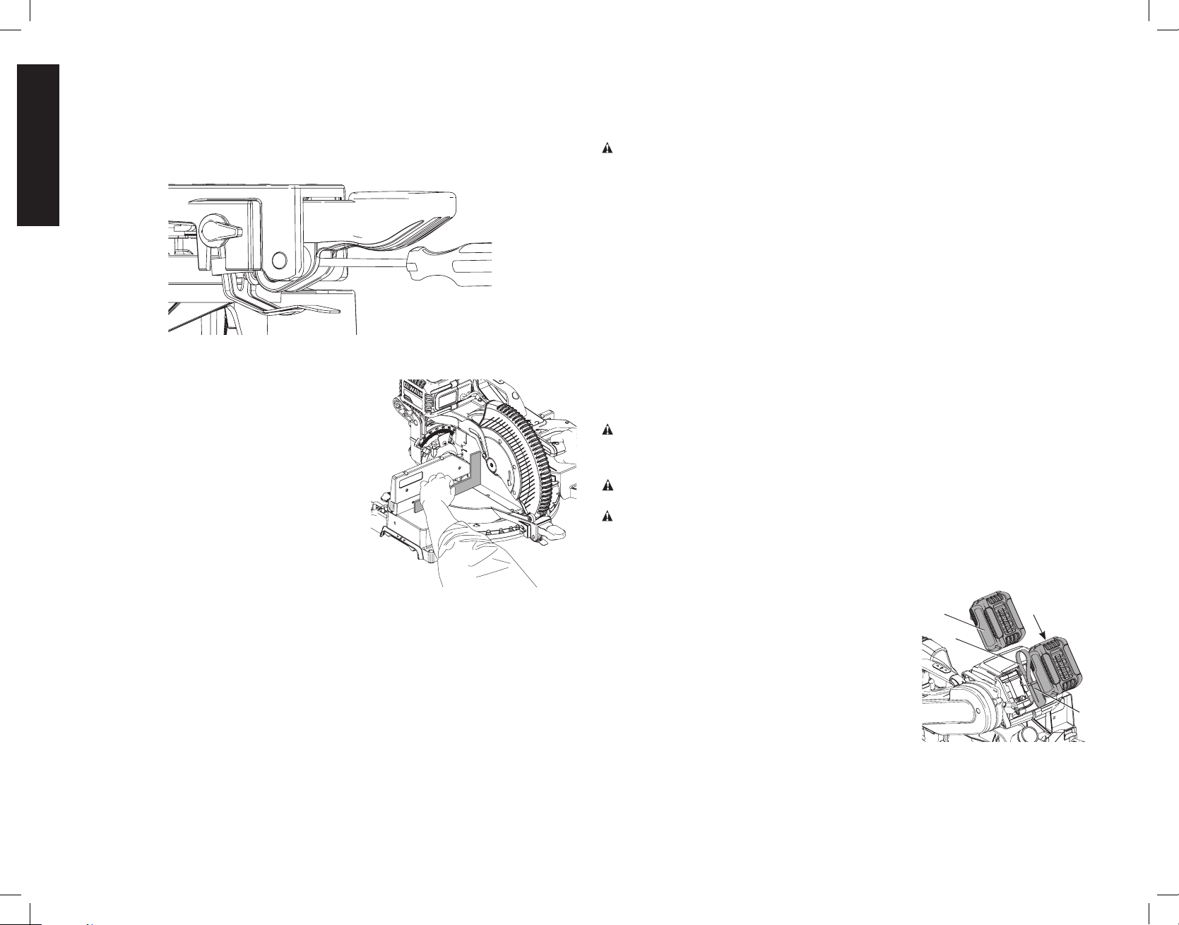
Installing and Removing the Battery Packs (Fig. 15)
NOTE: For best results, make sure your battery packs are fully charged.
To install the battery packs (T) into the tool, align the battery
T
FIG. 15
AK
AN
AO
packs with the rails on the side of the motor housing and
slide them in until they are firmly seated in the tool and
ensure that they do not disengage. Insert the dust cover
(AO) into the corded power supply receptacle (AN) in
between the batteries.
NOTICE: Keep the dust cover in place whenever
the corded power supply is not in use.
To remove the battery packs from the tool, press the
battery release button (AK) and firmly pull the battery
packs out. Insert them into the charger as described in
the charger section of this manual.
Installing and Removing the Corded Power Supply into
and from Tool (Fig.16–18)
Before inserting the corded power supply into your tool, remove the end of the dust cover
(AO) from the tool's corded power supply receptacle (AN). Pull the dust cover away from
the tool’s corded power supply receptacle so that it does not interfere with insertion of the
Loading ...
Loading ...
Loading ...