
Thermal Network Hybrid Pan & Tilt
Camera
Web Operation Manual
V2.0.1

I
Foreword
General
This user’s manual (hereinafter referred to as "the Manual") introduces the characteristics, basic
configurations, daily operation and maintenance of the thermal camera (hereinafter referred to as
"the Camera"). Read carefully before using the device, and keep the manual safe for future reference.
This manual is mainly for thermal hybrid pan & tilt cameras such as anti-corrosion hybrid speed
domes, anti-corrosion hybrid pan & tilt cameras, hybrid pan & tilt cameras, explosion-proof hybrid
pan & tilt cameras.
Ports
The Manual is mainly about on the web page, how to operate your Camera. For description of ports
such as ports connection and ports debugging, contact technical staffs.
Safety Instructions
The following signal words might appear in the manual.
Signal Words Meaning
Indicates a high potential hazard which, if not
avoided, will result in death or serious injury.
Indicates a medium or low potential hazard
which, if not avoided, could result in slight or
moderate injury.
Indicates a potential risk which, if not avoided,
could result in property damage, data loss,
lower performance, or unpredictable result.
Provides methods to help you solve a problem
or save you time.
Provides additional information as the
emphasis and supplement to the text.
Revision History
Version Revision Content Release Time
V2.0.1 Updated "Playback". March 2023
V2.0.0
●
Updated some pictures in the
document.
●
Updated "Smart Thermal"
December 2022
V1.0.5 Updated "Temperature Measuring Settings". June 2022
V1.0.4 Updated whole document. March 2020

II
Version Revision Content Release Time
V1.0.3
●
Modified function of safety
management.
●
Modified parameters of camera.
●
Updated some pictures in the
document.
●
Added GDPR requirements.
July, 2018
V1.0.2
●
Added Camera initialization.
●
Updated some pictures in the
document.
●
Added description of reserved spots’
input and output.
●
Added safety management.
February, 2017
V1.0.1 Added "Cybersecurity Recommendations". October, 2017
V1.0.0 First release. January, 2017
Privacy Protection Notice
As the device user or data controller, you might collect the personal data of others such as their face,
fingerprints, and license plate number. You need to be in compliance with your local privacy
protection laws and regulations to protect the legitimate rights and interests of other people by
implementing measures which include but are not limited: Providing clear and visible identification
to inform people of the existence of the surveillance area and provide required contact information.
About the Manual
●
The manual is for reference only. Slight differences might be found between the manual and the
product.
●
We are not liable for losses incurred due to operating the product in ways that are not in
compliance with the manual.
●
The manual will be updated according to the latest laws and regulations of related jurisdictions.
For detailed information, see the paper user’s manual, use our CD-ROM, scan the QR code or visit
our official website. The manual is for reference only. Slight differences might be found between
the electronic version and the paper version.
●
All designs and software are subject to change without prior written notice. Product updates
might result in some differences appearing between the actual product and the manual. Please
contact customer service for the latest program and supplementary documentation.
●
There might be errors in the print or deviations in the description of the functions, operations
and technical data. If there is any doubt or dispute, we reserve the right of final explanation.
●
Upgrade the reader software or try other mainstream reader software if the manual (in PDF
format) cannot be opened.
●
All trademarks, registered trademarks and company names in the manual are properties of their
respective owners.
●
Please visit our website, contact the supplier or customer service if any problems occur while
using the device.
●
If there is any uncertainty or controversy, we reserve the right of final explanation.

III
Statement
About the Manual
To simplify the description, the following conventions are made in this manual for common
functions, names, and more.
●
This manual is suitable for multiple models of products, and functions and pages vary from
models.
●
To protect personal privacy and security, personal information such as faces and license plates
appearing in this document has been masked.
●
To ensure the security of devices, the IP address, MAC address, serial number and other
information appearing in this document have been masked.
About the Format
Format Description Example
> Menu cascade.
Select
Setting
>
Smart Thermal
>
IVS
.
Bold
Page names, control names,
specification terms, and
more.
Click
Add Excluded Area
to draw an
excluded area on surveillance image.
Right-click to end drawing.
About the Icon/Button
Icon/Button Description
Text box. You can enter numbers, letters, Chinese characters,
symbols and other characters.
Drop-down box. Click the icon to display the drop-down menu.
Calendar. Click , and then select the date as needed.
Click the icon to select the corresponding item. indicates that
the item is selected. Click to cancel the selection.
Click the icon to select the corresponding item.
●
Click / to go to the previous or next page.
●
Click / to go to the first or last page.
Adjust the value. Click / or drag to adjust the value.
Click the button to save the configuration.
Click the button to display the latest configuration.
Click the button to restore the configuration to the factory
configuration.

IV
Table of Contents
Foreword
........................................................................................................................................................................................................I
Statement
.................................................................................................................................................................................................... III
1 Product Introduction
.......................................................................................................................................................................... 1
1.1 Overview
........................................................................................................................................................................................ 1
1.2 Features
.......................................................................................................................................................................................... 1
1.3 Functions
....................................................................................................................................................................................... 2
2 Configuration Flow
.............................................................................................................................................................................. 7
3 Basic Settings
.......................................................................................................................................................................................... 8
3.1 Initializing Camera
.................................................................................................................................................................... 8
3.2 Changing IP Address
................................................................................................................................................................ 9
3.2.1 Changing One IP Address
........................................................................................................................................... 9
3.2.2 Changing Several IP Addresses
............................................................................................................................. 10
3.3 Logging in to Web Page
....................................................................................................................................................... 11
3.4 Resetting Password
................................................................................................................................................................ 12
4 Daily Operation
................................................................................................................................................................................... 14
4.1 Live
.................................................................................................................................................................................................. 14
4.1.1 Introduction to Live Page
......................................................................................................................................... 14
4.1.2 Function Bar
.................................................................................................................................................................... 15
4.1.3 Window Adjustment
................................................................................................................................................... 15
4.1.3.1 Image Adjustment
............................................................................................................................................. 15
4.1.3.2 Display of Rule Information
.......................................................................................................................... 16
4.1.3.3 Zoom and Focus
.................................................................................................................................................. 16
4.1.3.4 Optical Axis Calibration
.................................................................................................................................. 16
4.1.3.5 Real-time Reports
.............................................................................................................................................. 16
4.1.4 Real-time Spot Temperature Measurement
.................................................................................................... 17
4.1.5 Laser Ranging
................................................................................................................................................................. 18
4.2 PTZ
.................................................................................................................................................................................................. 18
4.2.1 Configuring Protocol
.................................................................................................................................................. 18
4.2.1.1 Configuring Network PTZ
.............................................................................................................................. 18
4.2.1.2 Configure Analog PTZ
..................................................................................................................................... 19
4.2.2 Configuring PTZ Functions
...................................................................................................................................... 19
4.2.2.1 Configuring Preset
............................................................................................................................................ 19
4.2.2.2 Configuring Tour
................................................................................................................................................ 20
4.2.2.3 Configuring Scan
................................................................................................................................................ 21
4.2.2.4 Configuring Pattern
.......................................................................................................................................... 22

V
4.2.2.5 Configuring Pan
.................................................................................................................................................. 23
4.2.2.6 Configuring PTZ Speed
................................................................................................................................... 23
4.2.2.7 Configuring Idle Motion
................................................................................................................................. 24
4.2.2.8 Configuring Power Up
..................................................................................................................................... 25
4.2.2.9 Configuring Time Task
.................................................................................................................................... 25
4.2.2.10 Restarting PTZ
.................................................................................................................................................. 26
4.2.2.11 Default
.................................................................................................................................................................. 27
4.2.3 Calling PTZ
....................................................................................................................................................................... 28
4.2.3.1 PTZ Control
........................................................................................................................................................... 28
4.2.3.2 Joystick
.................................................................................................................................................................... 29
4.2.3.3 PTZ Functions
...................................................................................................................................................... 29
4.3 Playback
....................................................................................................................................................................................... 30
4.3.1 Prerequisite
..................................................................................................................................................................... 30
4.3.2 Playback Page
................................................................................................................................................................ 30
4.3.3 Playing back Video or Picture
................................................................................................................................. 32
4.3.4 Clipping Video
................................................................................................................................................................ 33
4.3.5 Downloading Video or Picture
............................................................................................................................... 34
4.4 Reports
.......................................................................................................................................................................................... 34
4.5 Alarm
.............................................................................................................................................................................................. 35
4.5.1 Introduction to Alarm Types
................................................................................................................................... 35
4.5.2 Subscribing Alarm Information
............................................................................................................................. 36
5 AI function
.............................................................................................................................................................................................. 38
5.1 Event
.............................................................................................................................................................................................. 38
5.1.1 Alarm Linkage
................................................................................................................................................................ 38
5.1.2 Setting Period
................................................................................................................................................................. 40
5.1.3 Configuring Video Detection
.................................................................................................................................. 41
5.1.3.1 Configuring Motion Detection
.................................................................................................................... 41
5.1.3.2 Configuring Video Tampering
.................................................................................................................... 43
5.1.4 Configuring Audio Detection
................................................................................................................................. 43
5.1.5 Configuring Temperature Alarm
.......................................................................................................................... 45
5.1.6 Configuring Abnormality
......................................................................................................................................... 46
5.1.6.1 Configuring SD Card Abnormality
............................................................................................................ 46
5.1.6.2 Configuring Network Abnormality
........................................................................................................... 46
5.1.6.3 Configuring Illegal Access
............................................................................................................................. 47
5.1.6.4 Configuring Burning Warning
..................................................................................................................... 47
5.1.6.5 Configuring High Humidity Alarm
............................................................................................................ 48
5.1.6.6 Configuring Security Exception
.................................................................................................................. 48
5.2 Temperature Measurement
............................................................................................................................................... 49

VI
5.2.1 Note
..................................................................................................................................................................................... 49
5.2.2 Configuration Flow
...................................................................................................................................................... 49
5.2.3 Configuring Thermal Image
.................................................................................................................................... 49
5.2.4 Configuring Burning Warning
................................................................................................................................ 53
5.2.5 Configuring Preset
....................................................................................................................................................... 54
5.2.6 Configuring Temperature Measurement Parameters
................................................................................ 54
5.2.6.1 Configuring Temperature Measuring Rules
......................................................................................... 54
5.2.6.2 Configuring Temperature Contrast
.......................................................................................................... 56
5.2.6.3 Configuring Global Setup
.............................................................................................................................. 57
5.2.7 Configuring Temperature Alarm
.......................................................................................................................... 59
5.2.8 Verification
...................................................................................................................................................................... 60
5.2.9 Isotherm
............................................................................................................................................................................ 61
5.3 Configuring IVS
......................................................................................................................................................................... 63
5.3.1 Scene-Selecting Requirements
.............................................................................................................................. 63
5.3.2 Configuration Flow
...................................................................................................................................................... 63
5.3.3 Configuring Preset
....................................................................................................................................................... 64
5.3.4 Configuring Smart Plan
............................................................................................................................................. 64
5.3.5 Configuring Intelligent Rules
................................................................................................................................. 65
5.3.6 Configuring Global Setup
......................................................................................................................................... 67
5.3.7 Configuring Auto Tracking
...................................................................................................................................... 68
5.4 Call Detection
............................................................................................................................................................................ 69
5.4.1 Configuration Flow
...................................................................................................................................................... 69
5.4.2 Configuring Preset
....................................................................................................................................................... 69
5.4.3 Configure Smart Plan
.................................................................................................................................................. 70
5.4.4 Configure Call Detection
........................................................................................................................................... 71
5.4.5 Configuring Global Setup
......................................................................................................................................... 72
5.5 Smoking Detection
................................................................................................................................................................. 73
5.5.1 Configuration Flow
...................................................................................................................................................... 73
5.5.2 Configuring Preset
....................................................................................................................................................... 73
5.5.3 Configure Smart Plan
.................................................................................................................................................. 74
5.5.4 Configure Smoking Detection
................................................................................................................................ 75
5.5.5 Configuring Global Setup
......................................................................................................................................... 76
5.6 Boat Detection
.......................................................................................................................................................................... 77
5.6.1 Note
..................................................................................................................................................................................... 77
5.6.2 Configuration Flow
...................................................................................................................................................... 77
5.6.3 Configuring Preset
....................................................................................................................................................... 77
5.6.4 Configure Smart Plan
.................................................................................................................................................. 78
5.6.5 Configuring Boat Detection
.................................................................................................................................... 79

VII
5.6.6 Configuring Global Setup
......................................................................................................................................... 81
5.6.7 Configuring Boat Calibration
................................................................................................................................. 81
5.7 Configuring Heat Warning
.................................................................................................................................................. 82
5.7.1 Note
..................................................................................................................................................................................... 82
5.7.2 Configuration Flow
...................................................................................................................................................... 83
5.7.3 Configuring North
........................................................................................................................................................ 83
5.7.4 Configuring Burning Warning
................................................................................................................................ 84
5.7.5 Configuring Pan
............................................................................................................................................................. 85
5.7.6 Configuring Heat
.......................................................................................................................................................... 87
5.7.7 Configuring Smoke Detection
................................................................................................................................ 89
5.7.7.1 Configuring Rule
................................................................................................................................................ 89
5.7.7.2 Configuring Smoke and Heat Detection Mode
................................................................................... 91
5.7.7.3 Verification
............................................................................................................................................................ 91
5.7.8 Configuring Idle Motion
............................................................................................................................................ 92
5.7.9 Configuring Heat Point Calibration
..................................................................................................................... 93
5.7.10 Configuring Heat Extension
................................................................................................................................. 95
5.8 Configuring Hot Trace
........................................................................................................................................................... 95
5.9 Configuring Pic in Pic
............................................................................................................................................................. 97
5.10 Configuring Link Schedule
............................................................................................................................................... 97
5.11 Configuring Thermal Map Acquisition
....................................................................................................................... 98
5.12 Configuring Fusion Calibrate
.......................................................................................................................................... 99
5.12.1 Note
................................................................................................................................................................................... 99
5.12.2 Calibration Flow
.......................................................................................................................................................... 99
5.12.3 Calibration
.................................................................................................................................................................. 100
6 Setting
................................................................................................................................................................................................... 101
6.1 Configuring Camera
............................................................................................................................................................ 101
6.1.1 Configuring Camera Conditions
........................................................................................................................ 101
6.1.1.1 Configuring Visible Image
.......................................................................................................................... 101
6.1.1.1.1 Configuring Picture Parameters
................................................................................................... 101
6.1.1.1.2 Configuring Exposure Parameters
.............................................................................................. 103
6.1.1.1.3 Configuring Backlight Parameters
.............................................................................................. 105
6.1.1.1.4 Configuring White Balance Parameters
................................................................................... 106
6.1.1.1.5 Configuring Day & Night Parameters
........................................................................................ 107
6.1.1.1.6 Configuring Focus & Zoom Parameters
.................................................................................... 108
6.1.1.1.7 Configuring Defog Parameters
..................................................................................................... 109
6.1.1.2 Configuring Thermal Image
...................................................................................................................... 110
6.1.1.3 Configuring Defective Pixel Correction
............................................................................................... 115
6.1.1.4 Configuring Profile Management
........................................................................................................... 116

VIII
6.1.2 Configuring Video Parameters
........................................................................................................................... 117
6.1.2.1 Configuring Video Streaming
................................................................................................................... 117
6.1.2.2 Configuring Image Streaming
.................................................................................................................. 119
6.1.2.3 Configuring Video Overlay
........................................................................................................................ 120
6.1.2.3.1 Configuring Privacy Masking
......................................................................................................... 120
6.1.2.3.2 Configuring Channel Title
............................................................................................................... 121
6.1.2.3.3 Configuring Time Title
....................................................................................................................... 122
6.1.2.3.4 Configuring OSD Info
......................................................................................................................... 122
6.1.2.3.5 Configuring Font
.................................................................................................................................. 123
6.1.2.3.6 Configuring Picture Overlay
........................................................................................................... 124
6.1.2.3.7 Configuring Voltage Information
................................................................................................ 125
6.1.2.4 Configuring ROI
............................................................................................................................................... 125
6.1.2.5 Configuring Storage Path
........................................................................................................................... 126
6.1.3 Configuring Audio Parameters
........................................................................................................................... 127
6.2 Configuring Network
.......................................................................................................................................................... 129
6.2.1 Configuring TCP/IP
.................................................................................................................................................... 129
6.2.2 Configuring Port
........................................................................................................................................................ 131
6.2.3 Configuring PPPoE
.................................................................................................................................................... 133
6.2.4 Configuring DDNS
..................................................................................................................................................... 134
6.2.5 Configuring SMTP
...................................................................................................................................................... 135
6.2.6 Configuring UPnP
...................................................................................................................................................... 136
6.2.7 Configuring SNMP
..................................................................................................................................................... 137
6.2.8 Configuring Bonjour
................................................................................................................................................ 139
6.2.9 Configuring Multicast
.............................................................................................................................................. 140
6.2.10 Configuring Auto Registration
......................................................................................................................... 141
6.2.11 Configuring 802.1X
................................................................................................................................................ 141
6.2.12 Configuring QoS
...................................................................................................................................................... 142
6.2.13 Platform Access
........................................................................................................................................................ 143
6.2.13.1 P2P
....................................................................................................................................................................... 143
6.2.13.2 ONVIF
................................................................................................................................................................. 143
6.2.13.3 RTMP
................................................................................................................................................................... 144
6.3 Storage
....................................................................................................................................................................................... 145
6.3.1 Configuring Schedule
.............................................................................................................................................. 145
6.3.1.1 Configuring Record Plan
............................................................................................................................. 145
6.3.1.2 Configuring Snapshot Plan
........................................................................................................................ 146
6.3.1.3 Configuring Holiday Schedule
................................................................................................................. 148
6.3.2 Configuring Storage Method
............................................................................................................................... 148
6.3.2.1 Configuring Storage Path
........................................................................................................................... 148

IX
6.3.2.2 Configuring Local Storage
......................................................................................................................... 149
6.3.2.3 Configuring FTP Server
................................................................................................................................ 149
6.3.2.4 Configuring NAS Server
............................................................................................................................... 150
6.3.3 Setting Record Control
............................................................................................................................................ 151
6.4 Peripheral
................................................................................................................................................................................. 152
6.4.1 Configuring Illuminator
......................................................................................................................................... 152
6.4.2 Configuring Wiper
..................................................................................................................................................... 152
6.4.3 Configuring Fan
.......................................................................................................................................................... 153
6.4.4 Configuring Heater
................................................................................................................................................... 153
6.5 System Management
.......................................................................................................................................................... 154
6.5.1 General Settings
......................................................................................................................................................... 154
6.5.1.1 Configuring General Information
........................................................................................................... 154
6.5.1.2 Configuring Date & Time
............................................................................................................................. 154
6.5.1.3 Configuring Position System
.................................................................................................................... 156
6.5.2 User Management
..................................................................................................................................................... 156
6.5.2.1 Adding a User
.................................................................................................................................................... 157
6.5.2.2 Adding a Group
................................................................................................................................................ 159
6.5.2.3 Modifying User Password
........................................................................................................................... 160
6.5.3 Adding ONVIF User
................................................................................................................................................... 162
6.5.4 Safety Management
................................................................................................................................................. 162
6.5.4.1 Configuring RTSP Authentication
.......................................................................................................... 162
6.5.4.2 Configuring System Service
...................................................................................................................... 163
6.5.4.3 HTTPS
.................................................................................................................................................................... 164
6.5.4.4 Firewall
................................................................................................................................................................. 169
7 System Maintenance
...................................................................................................................................................................... 171
7.1 Maintenance Requirements
............................................................................................................................................ 171
7.2 Auto Maintenance
................................................................................................................................................................ 171
7.3 Backing Up and Restoring
................................................................................................................................................ 171
7.3.1 Importing and Exporting
....................................................................................................................................... 171
7.3.2 Default Settings
.......................................................................................................................................................... 172
7.4 Upgrading Firmware
........................................................................................................................................................... 172
7.5 Information
.............................................................................................................................................................................. 173
7.5.1 Version
............................................................................................................................................................................ 173
7.5.2 Log
..................................................................................................................................................................................... 173
7.5.3 Remote Log
................................................................................................................................................................... 174
7.5.4 Online User
.................................................................................................................................................................... 175
Appendix 1 Cybersecurity Recommendations
..................................................................................................................... 176

1
1 Product Introduction
1.1 Overview
The Camera is based on requirements such as temperature measurement, fire prevention, safety
protection and night vision. It can help you view videos, record videos of objects, measure
temperature, warn the potential fire, track a cold/hot spot and analyze a special behavior. The
Camera can be used in energy industry, transportation, building, power system, public security,
government, enterprises, and other fields (such as science, education, culture and health). You can
use the Camera alone or combine the Camera with other storage devices to provide solutions for
intelligence city, production safety, safety protection of residential buildings and public area safety.
1.2 Features
●
Safe and stable.
●
With a full embedded system, this Camera can implement all-day monitoring in a stable way.
●
A long detection distance.
●
Wide monitoring range and long detection distance. Used for surveillance of wide range and
long distance.
●
Strong detection ability.
●
With night vision ability, this Camera can clearly distinguish different objects in the dark and can
tell camouflage and hidden objects.
●
Strong anti-interference ability.
●
This Camera can get rid of interference of light intensity under backlight or strong light
environment.
●
Adaptive capacity to complex environment.
●
Applicable to such environment as smoke, smog, rain, snow, and dust which will block your eyes
and is very confusing in colors.
This product can be used in various scenarios and the "small application scenarios" is used as an
example here for detailed description. See Figure 1-1.

2
Figure 1-1 Application scenarios
1.3 Functions
Live
Table 1-1 Function description
Function Description
Live
You can view both the visible images and thermal images.
You can use thermal images to identify an object, and then use visible
images to view more details of the object.
PTZ operation
For a PTZ camera, you can set the PTZ functions such as preset, tour,
pattern, pan, PTZ speed, idle motion, starting action and time task, to
enlarge the surveillance range and identify details of an object..
Voice intercom
For cameras with voice intercom function, you can talk indoors with a
person near the outdoor monitor to facilitate problem solution.
Snapshot
During live view, you can capture an abnormal image for further check
and handling.
Local recording
During live view, you can record abnormal images for further check
and handling.
Reports
For cameras with the temperature measurement function, you can
check the real-time temperature data of the monitoring area.
Real-time spot
temperature
measurement
For cameras with the temperature measurement function, you can
check the real-time temperature data of any spot in the monitoring
area.

3
Function Description
Laser ranging
For cameras with the laser ranging function, you can measure the
distance between the Camera and the object in the middle of the
image.
Additional functions
●
Switch video bit stream or streaming protocol.
●
The visible image will be adjusted to the relevant location when
you zoom in or out the thermal image.
●
Mark information as needed in the surveillance image.
●
Check whether there is any alarm output.
●
Magnify part of the surveillance image. Or, scroll the mouse to
zoom the whole surveillance image.
●
You can help the Camera focus manually on the web page.
●
Set a smart rule. When the rule is broken and an alarm is triggered,
you can track the target manually.
●
Adjust display effect of the surveillance images.
●
Enable or disable the intelligent rule display.
Playback
Table 1-2 Description of playback function
Function Description
Manual recording
When playing back a video, you can record the key information of the
video for further check and handling.
Planned recording
After you set a recording plan, the system will automatically record as
scheduled.
Video playback and
download
●
Play back a video to find some valuable video fragments.
●
Download the valuable video fragments for further judgment.
Picture playback Play back images that you have captured to find something valuable.
Alarm linkage
When there is an alarm, the system will automatically link the
corresponding channel to record videos.
Report
Follow certain rules such as time sequence to check history data of temperature stored in the Micro
SD card of the Camera.
Alarm
●
Set prompting mode (sound, for example) based on the alarm type.
●
View alarm information.
Account Management
Table 1-3 Function description
Function Description
Management of user
group
●
Add, modify or delete an account group.
●
Manage user permissions based on user groups.

4
Function Description
User Management
●
Add, modify or delete a user account.
●
Set the user permissions.
Change password Change users’ password.
Peripheral Management
You can manage your camera’s external devices such as heater, illuminator and wiper.
Smart Thermal
Table 1-4 Function description
Function Description
IVS
●
Both visible channel and thermal channel support intelligent rules,
including tripwire and intrusion.
●
When there is an alarm, the system performs linkage actions such
as video recording, alarm output, sending email, PTZ operation
and capturing images.
●
Supports adding detection area and exclusion area.
Calling Behavior
Detection
●
Available in visible channel.
●
When the Camera detects calling behavior, an alarm is triggered,
and the system performs linkage actions such as audio alarm,
white light, sending email and recording.
Smoking Detection
●
Available in visible channel.
●
When the Camera detects smoking behavior, an alarm is triggered,
and the system performs linkage actions such as audio alarm,
white light, sending email and recording.
Boat Detection
●
Available in thermal channel.
●
When the Camera detects unexpected boat, an alarm is triggered,
and the system performs linkage actions such as relay-out, sending
email and recording.
Fire Warning
●
Available in thermal channel.
●
When there is an alarm, the system performs linkage actions such
as linkage video recording, alarm output, sending email, PTZ
operation and capturing images.
Cold/hot spot tracking
●
Only thermal channel can implement the cold/hot spot tracking
operation.
●
Supports real-time display of the cold spot and hot spot by
different colors on the live image.
●
When there is an alarm, the system performs linkage actions such
as video recording, alarm output, sending email, PTZ operation
and capturing images.
Picture in picture
●
Only visible channel can implement the picture in picture
operation.
●
You can put the thermal image into the visible image.

5
Event
Table 1-5 Function description
Function Description
Video detection
●
You can implement operation of motion detection and video
masking detection.
●
When there is an alarm, the system performs linkage actions such
as video recording, alarm output, sending email, PTZ operation
and capturing images.
Audio detection
●
Supports detection of input exception and mutation of acoustic
intensity.
●
When there is an alarm, the system performs linkage actions such
as video recording, alarm output, sending email, PTZ operation
and capturing images.
Temperature alarm
●
When temperature satisfies the alarm conditions of temperature
testing rules, an alarm is triggered.
●
When there is an alarm, the system performs linkage actions such
as linkage video recording, alarm output, sending email, PTZ
operation and capturing images.
Alarm settings
●
The alarm is triggered when there is an alarm from external
cameras.
●
When there is an alarm, the system performs linkage actions such
as video recording, alarm output, sending email, PTZ operation
and capturing images.
Abnormality
●
Supports detection of SD card, network abnormality and illegal
access.
●
When there is SD card abnormality, network abnormality or
illegal access, the system performs linkage actions such as video
alarm output, and sending email.
●
When there is an alarm of network abnormality, the system
performs linkage actions such as video recording, and alarm
output.
Temperature Measuring Settings
This function is available on select models.
Table 1-6 Function description
Function Description
Temperature measuring
rules
●
Supports measuring average temperature, maximum
temperature and minimum temperature of spot, line, polygon
and ellipse’s.
●
Supports outputting alarm based on different conditions.
●
Supports setting different alarm output conditions to different
objects that need to be measured.

6
Function Description
Temperature contrast
●
Supports temperature contrast of different objects that needs to
be measured.
●
Supports outputting alarm based on different conditions.
●
Supports setting different alarm output conditions to different
temperature contrast rules.
Heat map
Supports outputting real-time heat map information. Then, you can
do the further analysis through the heat map tools.
Additional functions
●
Supports enabling or disabling temperature testing rules.
●
Supports enabling or disabling isotherm.
●
Supports enabling or disabling color code articles.

7
2 Configuration Flow
For the device configuration flow, see Figure 2-1. For details, see Table 2-1. Configure the device
according to the actual situation.
Figure 2-1 Configuration flow
Table 2-1 Description of flow
Configuration Description Reference
Login
Open IE browser and enter IP
address to log in to the web
interface, The camera IP address is
192.168.1.108 by default.
"3.3 Logging in to
Web Page"
Initialization
Initialize the camera when you use
it for the first time.
"3.1 Initializing
Camera"
Basic parameters
IP address
Change IP address according to
network planning for the first use or
during network adjustment.
"3.2 Changing IP
Address"
Date & time
Set date and time to ensure the
recording time is correct.
"6.5.1.2 Configuring
Date & Time"
Image
parameters
Adjust image parameters according
to the actual situation to ensure the
image quality.
"6.1.1 Configuring
Camera Conditions"
Intelligent Event
Detection
rules
Configure the necessary detection
rules, such as video detection and
IVS.
"5 AI function"
Subscribe
alarm
Subscribe alarm event. When the
subscribed alarm is triggered, the
system will record the alarm on the
alarm tab.
"4.5.2 Subscribing
Alarm Information"

8
3 Basic Settings
3.1 Initializing Camera
Initialize your Camera and set the user password when you are logging in for the first time or after
you have restored your camera to default settings. Initialize the Camera by ConfigTool or through
web page. This section takes web for example.
●
Ensure your Camera IP address (192.168.1.108 by default) and the IP address of your computer
are in the same network segment.
●
To secure the Camera data, keep admin password well after initialization and modify it regularly.
Step 1 Open a browser, enter the Camera default IP address in the address bar, and then press
Enter.
Figure 3-1 Initializing camera
Step 2 Set the login password for admin account.
Table 3-1 Password setting description
Parameter Description
Password Enter your password and enter it again to confirm it.
Use strong password. The password must consist of 8 to 32 non-blank
characters and contain at least two types of characters among upper
case, lower case, number, and special character (excluding ' " ; : &).
Confirm Password
Email Address Enter an email address to reset password when you forget it.
Step 3 Click
Save
.

9
3.2 Changing IP Address
Change the Camera IP address and ensure it is fitted to the actual network segment to get the
Camera access network.
You can change one or several IP addresses through ConfigTool. You can also log in to the web to
change IP addresses.
3.2.1 Changing One IP Address
When there are only a few cameras or the login passwords of the cameras are different, change one
IP address at one time. The chapter uses logging in to web page to change IP addresses as an
example.
Step 1 Log in to the Camera web page.
Step 2 Select
Setting
>
Network
>
TCP/IP
.
Figure 3-2 TCP/IP
Step 3 Configure TCP/IP parameters.
Table 3-2 TCP/IP parameters
Parameter Description
Host Name
Give your Camera a name (TPCDome, for example) to help others,
(a router operator, for example), know the camera information
such as shape information—dome thermal camera.
IP Address, Subnet Mask
and Default Gateway
Enter the three item values according to the actual network
segment.

10
Parameter Description
Ethernet Card, Mode, MAC
Address, IP Version,
Preferred DNS and
Alternate DNS
Leave them as default.
Step 4 Click
Save
.
3.2.2 Changing Several IP Addresses
When there are several cameras and the login passwords of cameras are the same, you can change
several IP address at the same time through the ConfigTool.
Prerequisites
●
You have obtained the installation package of ConfigTool. To obtain the installation package,
consult technical support staffs.
●
You have connected the camera with the computer with ConfigTool installed.
Procedure
Step 1 Click .
Step 2 Click
Search Settings
.
Step 3 Set the network segment of the Camera, admin and password. Then click
Save
.
After the search, the system displays the cameras that have been searched.
The user name and password are both admin by default.
Step 4 Select the cameras whose IP addresses need to be changed and click
Batch change IP
.
Figure 3-3 Change IP address
Step 5 Select the mode of IP address based on the actuality.
●
DHCP mode: When there is a DHCP server in the network, set the
Mode
as
DHCP
and
the Camera obtains IP addresses from the DHCP server automatically.
●
Manual mode: Set
Mode
as
Static
and enter
Starting IP
,
Subnet Mask
and
Gateway
.
Then, IP addresses of Cameras are incrementally modified from the start IP address.
Select the
Same IP
checkbox, the IP address of the selected devices will be set to the same

11
one. You can use this function when setting the IP addresses to default in batches.
Step 6 Click
Save
.
3.3 Logging in to Web Page
After you have changed the IP addresses, you can log in to the web page of the Camera through a
browser to operate, configure and maintain the Camera.
To log in to the Camera successfully, make sure that the computer connected to the Camera satisfies
the following requirements.
Table 3-3 Recommended PC configuration
PC items Recommended configuration
Operation system ≥ Windows 7
CPU ≥ Intel core i3
Graphics card ≥ Intel HD Graphics
Storage ≥ 2GB
Display ≥ 1024 × 768 Resolution
Browser Internet Explorer 9/10/11
Procedure
Step 1 Open the browser, enter the IP address in the address bar, and then press Enter.
Figure 3-4 Login
Step 2 Enter username and password, and click
Login
.
●
The user is admin by default. The password is the one that was configured during
initialization.
●
It will prompt you to install plug-in for the first system login. Please download and
install plug-in according to the prompt.
●
Functions might vary from different cameras.

12
Related Operations
Click
Logout
on the upper right corner to exit the page.
3.4 Resetting Password
If you forget the password, you can use the reserved e-mail address to achieve password resetting.
Step 1 Open IE browser, type the camera IP, and then press Enter.
Figure 3-5 Logging in the Camera
Step 2 Click
Forgot Password?
Figure 3-6 Reset the password (1/2)
Step 3 Reset the password.
Scan the QR code, and the security code will be sent to the email address that you have
configured. Type the security code.
●
Reset the password in time when you receive the security code, because the security

13
code will be invalid within 24 hours.
●
If you get security codes twice but do not use them, when you get the security code for
the third time, the system will prompt failure. To solve this problem, you need to
restore your Camera to default settings or wait 24 hours to get a new one.
Step 4 Click
Next
.
Figure 3-7 Resetting the password (2/2)
Step 5 Enter a new password and confirm it.
The password is made up of characters for 8–32 digits and the password must contain two
of the three forms (number, letter, and the common characters.
'
、
"
、
;
、
:
、
&
are not
included.) You should obey the prompt of the password’s security level and set a password
with high security level.
Step 6 Click
Save
.
The login page is displayed.

14
4 Daily Operation
4.1 Live
Cameras of different models might have different functions.
On the
Live
page, you can do operations to the real-time surveillance images such as viewing,
capturing images and recording videos.
●
Image channel with a box around is the one that you have selected. All your operations are valid
only to this channel.
●
Double-click an image channel and the image channel is displayed in a full video display area.
Double-click the image channel again and the channel will be displayed in a full screen. Right-
click the full-screen image and the image returns to its previous state.
4.1.1 Introduction to Live Page
Click the
Live
tab.
Figure 4-1 Live page
Table 4-1 Description of function bar
No. Name Description
1 System menu
Click each function tab in the system menu to go to the
corresponding page.
2 Live view Displays the real-time monitoring image.

15
No. Name Description
3 Encode bar
Select the bit stream type and streaming protocol when viewing
a video.
●
Main Stream: It has large bit stream value and image with
high resolution, but also requires large bandwidth. This
option is normally used for storage and surveillance.
●
Sub Stream: It has small bit stream value and smooth image,
and requires little bandwidth. This option is normally used
to replace main stream when bandwidth is not enough.
●
Protocol: A network transmission protocol, supports TCP
(Transmission Control Protocol), UDP (User Datagram
Protocol) and Multicast.
4
Live view function
bar
For functions and operations on live view. For details, see "4.1.2
Function Bar".
5 PTZ control For details of PTZ control, see "4.2 PTZ".
6
Adjustment bar of
video window
Supports adjusting clarity of video images, displaying intelligent
rules, zooming with focusing at the same time, checking real-
time reports. See "4.1.3 Window Adjustment".
4.1.2 Function Bar
Figure 4-2 Live view function
4.1.3 Window Adjustment
Figure 4-3 Window adjustment
4.1.3.1 Image Adjustment
Adjust brightness, contrast, hue and saturation of video images on the web page.
Click , and the
Image Adjustment
page is displayed at the right side of the live page.
Figure 4-4 Image adjustment page

16
Table 4-2 Image adjustment configuration
Icon Function Description
Brightness
Adjusts the overall image brightness, change the value
when the image is too bright or too dark. The bright and
dark areas have equal changes.
Contrast
Change the value when the image brightness is proper
but contrast is not enough.
Hue
Makes the color deeper or lighter. The default value
made by the light sensor is recommended.
Saturation
Adjusts color depth. This value does not change the
overall image brightness.
Reset
Click the icon to reset brightness, contrast, hue and
saturation to their default values.
4.1.3.2 Display of Rule Information
You can control whether rule information is displayed on the live page. The rule information is
displayed by default.
After configuring the AI functions, click , and then select the
Enable
checkbox to display rule
information and detection box; select the
Disable
checkbox to hidden the rule information and
detection box.
4.1.3.3 Zoom and Focus
Zooming and focusing functions are only available on motorized vari-focal Cameras.
Adjust focal length of the lens to zoom in or out surveillance images; adjust optical back-focus of the
lens to improve clarity of the video image.
Click , and the zooming and focusing page is displayed at the right side of live page.
●
Select the visible channel and you can zoom, focus and change the aperture.
●
Select the thermal channel and you can zoom and focus.
Table 4-3 Zoom and focus description
Parameters Description
Variable focal length
Click or , and adjust the optical back focal length of thermal
channel to make images clearer.
Auto focus Auto focus.
4.1.3.4 Optical Axis Calibration
Used only for calibrating the Camera lens when the Camera is being debugged in the factory. You do
not need to operate this function.
4.1.3.5 Real-time Reports
Records the changes of the average temperature of the spot, lines and area that you have selected

17
within the configured time. This function is available on Cameras with the temperature
measurement function.
Prerequisites
You have configured the temperature measurement rules. For detailed operation, see "5.2.6.1
Configuring Temperature Measuring Rules".
Procedure
Step 1 Click .
Step 2 Select the temperature measurement program and set the time period.
The real-time temperature change is displayed.
Figure 4-5 Temperature recording area
4.1.4 Real-time Spot Temperature Measurement
This function is available on Cameras with the temperature measurement function.
Click any spot on the video image, and the real-time temperature of this spot is displayed.
Figure 4-6 Real-time spot temperature measurement

18
4.1.5 Laser Ranging
This function is available on the cameras with the laser ranging function.
●
The laser can cause permanent damage to human eyes and skin within safe distance. Keep the
Camera a safe distance away from humans while installing or operating the device.
●
Laser radiation can ignite flammables. Do not directly expose objects (excluding scattered or
absorber) to the laser beam, and do not place volatile flammables (such as alcohol) in the
working area of laser radiation products, to avoid producing laser beams or fire caused by sparks
from high voltage discharge.
Mind the distance during laser ranging. Less than 50 m will result in a damaged laser.
●
Laser ranging does not perform well to those objects (such as glass and marble) with strong
reflection ability. During laser ranging, select those objects with rough surface as your target.
●
Do not use the distance measurer to measure the distance of targets that are within 50 m of the
laser. The laser can permanently damage the device.
Log in to the web page, and then click
Start Ranging
. The Camera starts to measure the distance
from the object in the middle of the image to it (as indicated with the red cross sign).
4.2 PTZ
4.2.1 Configuring Protocol
If you want to use the external devices (such as network keyboard, NVR) to control the Camera, you
need to set the protocol to connect them to the Camera.
4.2.1.1 Configuring Network PTZ
Step 1 Select
Setting
>
PTZ
>
Protocol
>
Network PTZ
.
Step 2 Select the protocol that is matched with the Camera.
Figure 4-7 Configure network PTZ
Step 3 Click
Save
.

19
4.2.1.2 Configure Analog PTZ
Step 1 Select
Setting
>
PTZ
>
Protocol
>
Analog PTZ
.
Step 2 Select the
Enable
checkbox.
Figure 4-8 Configure analog PTZ
Step 3 Configure the parameters.
Table 4-4 Description of analog PTZ configuration
Parameter Description
Address The IP address of the Camera.
Baud Rate
Select the baud rate of the external PTZ camera.
Set the baud rate same with that of the controlling camera; otherwise
you cannot control the external PTZ camera through the Camera.
Data Bit It is 8 by default.
Stop Bit It is 1 by default.
Parity It is
NONE
by default.
Step 4 Click
Save
.
4.2.2 Configuring PTZ Functions
Select
Setting
>
PTZ
>
Function
.
The thermal image is displayed by default. Click or to switch the image between the
thermal and visible images.
4.2.2.1 Configuring Preset
Preset means a certain position that the Camera can make quick orientation to. It includes PTZ pan
and tilt angles, camera focus, and location.

20
Procedure
Step 1 Select
Setting
>
PTZ
>
Function
.
Figure 4-9 Preset
Step 2 Configure preset.
1) Click
Add
to add a new preset.
2) Operate the PTZ control panel to move the camera lens to a specific direction that you
need.
3) Double-click
Preset Title
to modify the title of the preset.
4) click .
Related Operations
●
Click to delete a preset.
●
Click
Delete
to delete all the presets that you have added.
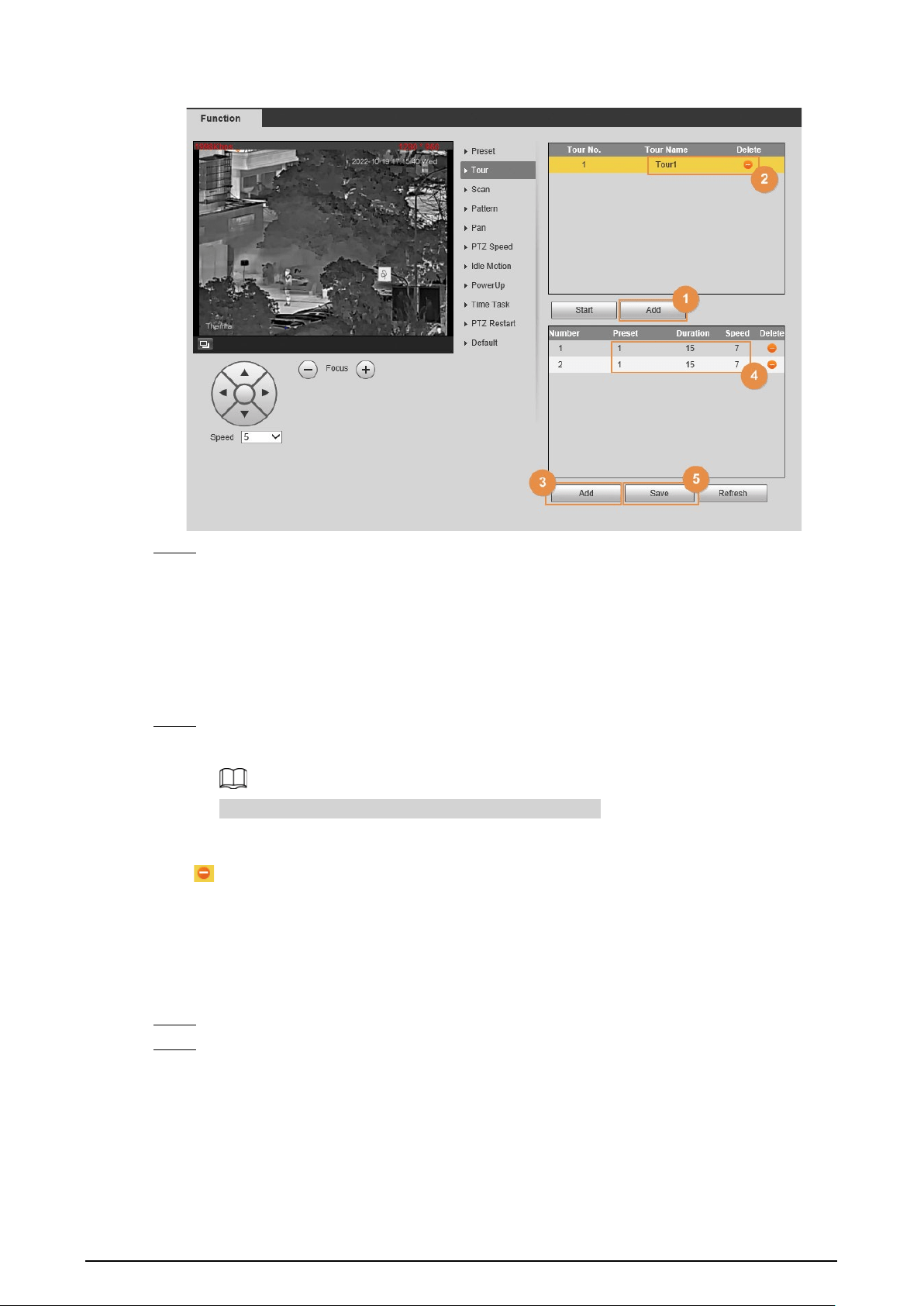
4.2.2.2 Configuring Tour
Tour means a series of movements that the Camera makes along several presets.
Prerequisites
You have configured several presets.
Procedure
Step 1 Select
Setting
>
PTZ
>
Function
>
Tour
.
21
Figure 4-10 Tour
Step 2 Configure tour.
1) Click
Add
to add a tour.
2) Double-click the touring name that you have added to modify it.
3) Click
Add
to add a preset.
Click repeatedly to add several presets.
4) Double-click to select a preset. And double-click to configure the lasting time.
5) Click
Save
.
Step 3 Select a tour and click
Start
to start camera tour.
Click
Stop
to stop the tour.
If you operate the PTZ during the tour, the tour will stop.
Related Operations
Click to delete a tour or a preset.
4.2.2.3 Configuring Scan
Scan means the Camera moves horizontally at a certain speed between the configured left and right
limits.
Step 1 Select
Setting
>
PTZ
>
Function
>
Scan
.
Step 2 Configure scan.
1) Select a
Scan No.
and set its
Speed
.
2) Click
Setup
.
Buttons of
Set Left Limit
and
Set Right Limit
are displayed.
3) Operate the PTZ control panel and rotate the Camera to a left border that you want and
click
Set Left Limit
; rotate the Camera to a right border that you want and click
Set
Right Limit
.

22
Figure 4-11 Scan
Step 3 Select a
Scan No.
and click
Start
to start the scan.
Click
Stop
to stop the scan.
4.2.2.4 Configuring Pattern
Pattern means a recording of a series of operations that you make to the Camera, and when pattern
starts, the camera performs the operations repeatedly. The operations include horizontal and
vertical movements, zoom and preset calling. Record and save the operations, and then you can call
the pattern path directly.
Step 1 Select
Setting
>
PTZ
>
Function
>
Pattern
.
Step 2 Configure pattern.
1) Select a
Pattern No
.
2) Click
Setup
.
Buttons of
Start Rec
and
Stop Rec
are displayed.
3) Click
Start Rec
.
4) Operate the PTZ control panel and adjust the direction of the Camera, zoom and focus.
5) Click
Stop Rec
.

23
Figure 4-12 Pattern
Step 3 Select a
Pattern No
, and click
Start
to start the pattern.
Click
Stop
to stop the pattern.
4.2.2.5 Configuring Pan
Enable Pan, the Camera can realize continuous 360° horizontal rotations at a certain speed.
Step 1 Select
Setting
>
PTZ
>
Function
>
Pan
.
Figure 4-13 Pan
Step 2 Set the pan speed, and then click
Start
to start the pan.
Click
Stop
to stop the pan.
4.2.2.6 Configuring PTZ Speed
PTZ speed means the rotation speed of the PTZ camera during touring, pattern, or auto tracking.
Step 1 Select
Setting
>
PTZ
>
Function
>
PTZ Speed
.

24
Figure 4-14 PTZ speed
Step 2 Select from
Low
,
Middle
and
High
. The configuration takes effect immediately.
4.2.2.7 Configuring Idle Motion
Idle motion means that the PTZ camera implements the operation which is configured in advance
when it does not receive any valid command within the set time.
You have configured preset, tour, scan and pattern before configuring idle motion.
Procedure
Step 1 Select
Setting
>
PTZ
>
Function
>
Idle Motion
.
Figure 4-15 Idle motion
Step 2 Configure idle motion.
1) Select the
Enable
checkbox to enable this function.
2) Select an idle motion and set idle time.

25
3) Click
Save
.
4.2.2.8 Configuring Power Up
After setting Power up motion, the Camera will perform the configured motion after it is powered
on.
Step 1 Select
Setting
>
PTZ
>
Function
>
Power Up
.
Figure 4-16 Power up
Step 2 Select the
Enable
checkbox.
Step 3 Select the
Power Up
actions.
Select
Auto
and the PTZ will continue to implement the action before the power is off.
Step 4 Click
Save
.
4.2.2.9 Configuring Time Task
After setting time task, the Camera performs the motions during the configured period.
You have configured preset, tour, scan and pattern before configuring time task.
Procedure
Step 1 Select
Setting
>
PTZ
>
Function
>
Time Task
.

26
Figure 4-17 Time task
Step 2 Configure time task.
1) Select the
Enable
checkbox to enable this function.
2) Select a number in
Time Task num
.
3) Select a time task action from
Preset
,
Tour
,
Scan
and
Pattern
.
When you set
Preset
as a time task action, the
Action Number
box is displayed. You
can select the action number as needed.
4) In the
AutoHome
box, set the time for the camera to return to its previous condition.
Auto home time: Time for the Camera to return to its previous condition and continue
the time task when the time task is interrupted by manual operation.
5) Click
Period Setting
to set the detailed period for a time task.
6) Click
Save
.
Step 3 (Optional) Copy a time task.
Copy task information that you have configured to other tasks.
1) Select a time task number that you have already configured.
2) In
Copy To Task No.
, select a task number to be configured.
3) Click
Copy
.
4) Click
Save
.
4.2.2.10 Restarting PTZ
Step 1 Select
Setting
>
PTZ
>
Function
>
PTZ Restart
.

27
Figure 4-18 PTZ restart
Step 2 Click
PTZ Restart
, and then PTZ restarts.
4.2.2.11 Default
Be careful when doing this operation. It will restore the Camera to default configuration, and result
in data loss.
Step 1 Select
Setting
>
PTZ
>
Function
>
Default
.
Figure 4-19 Default

28
Step 2 Click
Default
.
All your PTZ configurations are restored to the default ones.
4.2.3 Calling PTZ
Click on the
Live
page, and the PTZ configuration panel is displayed. You can control PTZ and
call PTZ function.
4.2.3.1 PTZ Control
You can rotate the Camera, zoom image, and adjust iris through PTZ control or virtual joystick.
Before using the
PTZ Control
panel, you need to set the PTZ protocol by selecting
Setting
>
PTZ
>
Protocol
.
Figure 4-20 PTZ control
Table 4-5 Parameter description
No. Function Description
1 Direction button
There are 8 directions: up, down, left, right, upper
left, upper right, lower left, and lower right.
2 Position
Provides quick positioning function. Draw a box on
the live view with the mouse, and then the PTZ
rotates to and focuses on the selected area rapidly.
3 Speed
The changing speed of PTZ direction. The higher
the value, the faster the speed.
4 Zoom, focus and iris
Click to increase the value, and click to
decrease the value.

29
4.2.3.2 Joystick
You can drag the middle button to simulate joystick operations to control device rotation. Speed,
zoom, focus, and iris configurations are the same as that of
PTZ Control
panel.
Figure 4-21 PTZ control panel
4.2.3.3 PTZ Functions
Call the configured PTZ functions on the live page. The PTZ supports multiple functions.
On the live page, click , and then select a function. Click or to start using
the function, and then click to stop using the function.
Before calling the function, configure PTZ functions first. For details, see "4.2.2 Configuring PTZ
Functions".
Figure 4-22 PTZ functions
Table 4-6 Description of PTZ function
Parameter Description
Scan
Select
Scan
from the list, enter a scan number, and then click
Start
to start
the scan; click
Stop
to stop the scan.
Preset
Select
Preset
from the list, enter a preset number, and then click
Go to
.
The PTZ will rotate to the preset position.

30
Parameter Description
Tour
Select
Tour
from the list, enter a tour number, and then click
Start
to start
the tour; click
Stop
to stop the tour.
Pattern
Select
Pattern
from the list, enter a pattern number, and then click
Start
to start the pattern; click
Stop
to stop the pattern.
Assistant
Reserved for special requirements.
If necessary, enable this function under the guidance of professionals.
Pan
Select
Pan
from the list, and then click
Start
to start the pan; click
Stop
to
stop the pan.
Go to
Select
Go to
from the list, enter horizontal angle value, vertical angle value
and zoom, and then click
Go to
. The Device will turn to the position that
you want.
Wiper Set the wiper of the Camera. Click
Once
to enable the wiper function.
4.3 Playback
This section introduces playback related functions and operations, including video playback and
picture playback.
4.3.1 Prerequisite
●
Before playing back video, configure record time range, record storage method, record schedule
and record control. For details, see "6.3.1.1 Configuring Record Plan".
●
Before playing back picture, configure snapshot time range, snapshot storage method, and
snapshot plan. For details, see "6.3.1.2 Configuring Snapshot Plan".
●
If you want to store videos and pictures in an SD card, make sure that you have inserted the SD
card in the Camera.
4.3.2 Playback Page
Click the
Playback
tab.
Figure 4-23 Video playback

31
Figure 4-24 Picture playback
Table 4-7 Playback page description
No. Function Description
1 Rules Info
Click , intelligent rules and object detection box are
displayed. It is enabled by default.
Rules Info is valid only when you enabled the rule during
recording.
2 Sound
Controls the sound during playback.
●
: Mute mode.
●
: Vocal state. You can adjust the sound.
3 Play control bar
Controls playback.
●
: Click the icon to play back recorded videos.
●
: Click the icon to stop playing back recorded videos.
●
: Click the icon to play the next frame.
●
: Click the icon to slow down the playback.
●
: Click the icon to speed up the playback.
4 Progress bar
Displays the record type and the corresponding period.
●
Click any point in the colored area, and the system will play
back the recorded video from the selected moment.
●
Each record type has its own color, and you can see their
relations in
Record Type
bar.
5
Record/Snapshot
Type
Select the record type or snapshot type.
●
Record type includes
General
,
Event
,
Alarm
,
Manual
.
●
Snapshot type includes
General
,
Event
,
Alarm
.
6 Assistant
Click the icon to capture one picture of the current video, and it
will be saved to the configured storage path.
7 Playback video You can select the file type, data source, and record date.
8 Video clip
Clip a certain recorded video and save it. For details, see "4.3.4
Clipping Video".

32
No. Function Description
9
Time format of
progress bar
Includes 4 time formats: , , ,
. Take as an example, the whole progress
stands for 24 hours.
4.3.3 Playing back Video or Picture
This section introduces the operation of video playback and picture playback. This section uses
video playback as an example.
Step 1 Select
dav
from the
Record Type
drop-down list and
SD card
from the
Data Src
drop-
down list.
Select
jpg
from
Record Type
drop-down list when playing back pictures, and you do not
need to select data source.
Figure 4-25 File type selection
Step 2 Select the channel as needed.
Step 3 Select the record type in
Record Type
.
Figure 4-26 Record type selection
Step 4 Select the month and year of the video that you want to play.
Those dates with blue color indicate there were videos recorded in those days.
Step 5 Play video.
●
Click in the control bar.
The system plays the recorded video of the selected date (in the order of time).
●
Click any point in the colored area on the progress bar.
The playback starts from that moment.

33
Figure 4-27 Progress bar
●
Click , the video files of the selected date will be listed. Enter the start time and
end time, and then click to search all files between the start time and end time.
Double-click the file in the list, and the system plays the video and displays file size,
starting time, and ending time.
Figure 4-28 Playback file list
4.3.4 Clipping Video
Step 1 Click the
Playback
tab.
Step 2 Click , the video files of the selected date are listed.
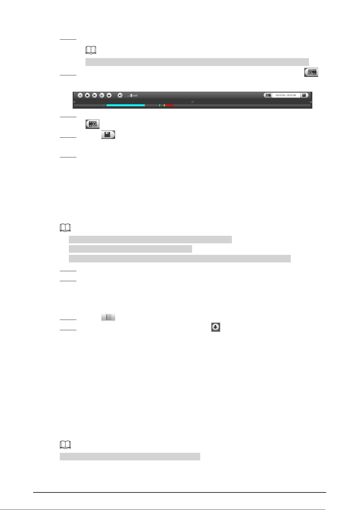
34
Step 3 Select
dav
or
mp4
in
Download Format
.
If you select
dav
, the rule information can be displayed when playing back the video.
Step 4 Click on the progress bar to select the start time of the target video, and then click .
Figure 4-29 Clip video
Step 5 Click again on the progress bar to select the end time of the target video, and then click
.
Step 6 Click to download the video.
The system will prompt that you cannot download the file and play back at the same time.
Step 7 Click
OK
.
The playback stops and the clipped file is saved in the configured storage path. For the
configuration of storage path, see "6.1.2.5 Configuring Storage Path".
4.3.5 Downloading Video or Picture
Download video or picture to a defined path. This section uses downloading video as an example.
●
Playback and downloading at the same time is not supported.
●
Operations might vary with different browsers.
●
For details of viewing or setting storage path, see "6.1.2.5 Configuring Storage Path".
Step 1 Click the
Playback
tab.
Step 2 Select
dav
from the
Record Type
drop-down list and
SD card
from the
Data Src
drop-
down list.
Select
jpg
from
Record Type
drop-down list when playing back pictures, and you do not
need to select data source.
Step 3 Click , the video files of the selected date are listed.
Step 4 Select
dav
or
mp4
in
Download Format
. Click next to the file to de download.
The system starts to download the file and save it to the configured path. When
downloading pictures, you do not need to select the download format.
4.4 Reports
You can follow certain rules such as time sequence, and check history data of temperature stored in
the Micro SD card.
●
You have configured the temperature measurement rules (including spots, lines and area). For
details, see "5.2.6.1 Configuring Temperature Measuring Rules".
●
You have inserted a SD card to the Camera.
This function is only available on some select models.

35
Procedure
Step 1 Click the
Report
tab.
Step 2 Set the conditions for searching and click
Search.
The searched temperature data is displayed.
Figure 4-30 History report
4.5 Alarm
You can select alarm type as needed. When the selected alarms are triggered, the system would
record detailed alarm information at the right side of the page.
Function of different Cameras might vary.
4.5.1 Introduction to Alarm Types
Table 4-8 Alarm type description
Alarm Type Description Condition
Motion detection
An alarm is triggered when a
moving object is detected.
You have enabled motion detection.
For details, see "5.1.3.1 Configuring
Motion Detection".
Disk full
An alarm is triggered when the
free space in the SD card is lower
than the configured percentage.
You have enabled detection to lack of
SD card storage space. For details, see
"5.1.6.1 Configuring SD Card
Abnormality".
Disk error
An alarm is triggered when there
is SD card error or abnormality.
You have enabled detection to SD
card storage space. For details, see
"5.1.6.1 Configuring SD Card
Abnormality".

36
Alarm Type Description Condition
External alarm
An alarm is triggered when there
is an alarm from external Camera.
There is an alarm input port and the
external alarm is enabled. For details,
see "5.1.1 Alarm Linkage".
Illegal access
An alarm is triggered when the
login password has been wrongly
entered for more than the set
times.
You have enabled detection to illegal
access. For details, see "5.1.6.3
Configuring Illegal Access".
Audio detection
An alarm is triggered when there
is an audio input error.
You have enabled detection to audio
errors. For details, see "5.1.4
Configuring Audio Detection".
Smart thermal
An alarm is triggered when the
IVS, call detection, smoking
detection or boat detection is
triggered.
●
You have enabled IVS. For details,
see "5.3 Configuring IVS".
●
You have enabled call detection.
For details, see "5.4 Call
Detection".
●
You have enabled smoking
detection. For details, see "5.5
Smoking Detection".
●
You have enabled boat detection.
For details, see "5.6 Boat
Detection" .
Heat warning
An alarm is triggered when a fire
point is detected.
You have enabled fire alarm. For
detailed operation, see "5.7
Configuring Heat Warning".
Temperature
alarm
When temperature satisfies alarm
conditions stipulated by
temperature testing rules, an
alarm is triggered.
You have enabled temperature alarm.
For detailed operations, see "5.2.6.1
Configuring Temperature Measuring
Rules".
Temperature
difference alarm
When temperature difference
satisfies alarm condition you have
set, an alarm is triggered.
You have enabled temperature
comparison alarm. For detailed
operations, see "5.2.6.2 Configuring
Temperature Contrast".
Hot spot alarm
When temperature of a hot spot
satisfies alarm condition you have
set, an alarm is triggered.
You have enabled hot/cold spot
tracing. For detailed operations, see
"5.8 Configuring Hot Trace".
Cold spot alarm
When temperature of a cold spot
satisfies alarm condition you have
set, an alarm is triggered.
4.5.2 Subscribing Alarm Information
You can enable alarm prompts and define alarm sound according to your preference.
Step 1 Click the
Alarm
tab.

37
Figure 4-31 Alarm
Step 2 Select an alarm type.
Step 3 Select
Prompt
, and the system prompts and records alarm information as needed.
●
If you are not on the
Alarm
page when alarm events that you have subscribed are
triggered, is displayed on the
Alarm
tab and the alarm information will be
recorded. Click the
Alarm
tab, and the sign disappears.
●
If you are on the
Alarm
page when the selected alarm is triggered, there will be
detailed alarm information displayed at the right side of the page.
Step 4 Select the
Play Alarm Tone
checkbox, and then select an audio file.
System would play the audio file that you have selected, when alarm events that you have
subscribed are triggered.
Click
Clear
to remove all the alarm information.
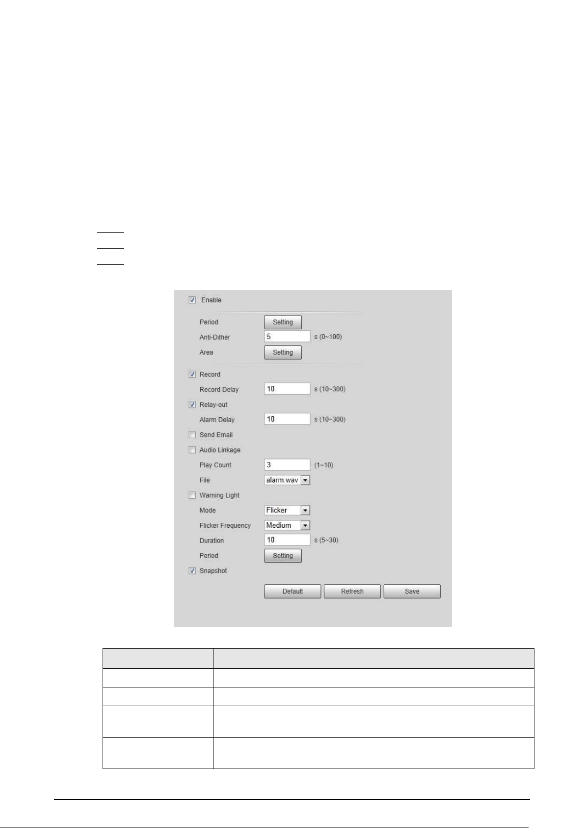
38
5 AI function
5.1 Event
5.1.1 Alarm Linkage
When the configured alarm is triggered in the configured arming period, the system will alarm.
Pages might vary with different models.
Step 1 Select
Setting
>
Event
>
Alarm
.
Step 2 Select the
Enable
checkbox.
Step 3 Configure the parameters of alarm linkage.
Figure 5-1 Alarm linkage
Table 5-1 Description of alarm linkage parameters
Parameter Description
Relay-in Select the external alarm device.
Period Set arming periods. For details, see "5.1.2 Setting Period".
Anti-Dither
After the anti-dither time is configured, the system only records one
motion detection event in the period.
Sensor Type
Select
NO
(normally open) or
NC
(normally closed) according to the
sensor type of external alarm device.

39
Parameter Description
Record
●
Record: Select the channel number. The system can link record
channel when an alarm event occurs.
●
Record Delay: After alarm, the system stops recording after an
extended time period according to the configured time.
●
To use the record linkage function, configure record plan for
motion detection alarm and enable auto recording in record
control. For details, see "6.3 Storage".
●
For the configuration of storage path, see "6.1.2.5 Configuring
Storage Path".
Relay-out
●
Relay-out: When an alarm is triggered, the system can
automatically link with relay-out device.
●
Alarm Delay: When alarm delay is configured, the alarm continues
for an extended period after the alarm ends.
Before enabling this function, make sure that you have connected
alarm devices (such as light and siren) to the Camera.
Send Email
When an alarm is triggered, the system will automatically send an email
to users.
Email linkage takes effect only when SMTP is configured. For details, see
"6.2.7 Configuring SNMP".
PTZ
Select the checkbox, activation and the number. When an alarm is
triggered, the system links PTZ to do operations.
Configure the PTZ function before enabling this function. For details,
see "4.2 PTZ".
Audio
●
The system broadcasts alarm audio file when an alarm event
occurs.
●
Play mode: Select and configure
Play Duration
and
Play Count
according to the play mode.
●
File: Select
Setting
>
Camera
>
Audio
>
Alarm Audio
to set alarm
audio file.

40
Parameter Description
Warning Light
When an alarm is triggered, the system can automatically enable the
warning light.
●
Mode
: The display mode of the warning light when an alarm is
triggered. It includes
Normally on
and
Flicker
. When setting
Flicker
as the mode, you need to set the flicker frequency.
For the Camera with red and blue alarm light, you can only select
Flicker
in
Mode
.
●
Duration
: After setting warning light duration, the warning light is
turned off after an extended time of period after an alarm. It is 5
seconds–30 seconds.
●
Period
: The period for using warning light. When an alarm
triggered during the configured period, the system links warning
light. For the configuration, see "5.1.2 Setting Period".
snapshot
After snapshot linkage is configured, the system can automatically
alarm and capture images when an alarm is triggered.
For the configuration of storage path, see "6.1.2.5 Configuring Storage
Path".
Step 4 Click
Save
.
5.1.2 Setting Period
Set arming periods. The Camera only performs corresponding linkage action in the configured
period.
Step 1 Click
Setting
next to
Period
.

41
Figure 5-2 Period
Step 2 Set arming periods. Alarms will be triggered in the time period in green on the timeline.
●
Method one: Directly press and drag the left mouse button on the timeline.
●
Method two: Enter an actual time period.
1. Click
Setting
next to a day.
2. Select a time period to be enabled.
3. Enter the start time and end time of a time period.
◇
Select
All
or the checkboxes of some days to set the time period of multiple days
at one time.
◇
You can set 6 time periods per day.
Step 3 Click
Save
.
5.1.3 Configuring Video Detection
Check whether there are considerable changes on the video by analyzing video images. In case of
any considerable change on the video (such as moving object, fuzzy image), the system performs an
alarm linkage.
5.1.3.1 Configuring Motion Detection
When the moving object appears on the image and its moving speed reaches the preset sensitivity,
the Camera performs an alarm linkage.
Step 1 Select
Setting
>
Event
>
Video Detection
>
Motion Detection
.

42
Figure 5-3 Motion detection
Step 2 Select the
Enable
checkbox.
Step 3 Configure a motion detection area.
1) Click
Setting
next to
Area
.
Figure 5-4 Area configuration
2) Select a color and set the region name. Select an effective area for Motion Detection in
the image and set
Sensitivity
and
Threshold
.
●
Select a color from to set different detection parameters for each

43
region.
●
Sensitivity: Sensitive degree of changes. The higher the sensitivity is, the easier the
alarm is triggered..
●
Threshold: Effective area threshold for Motion Detection. The smaller the threshold
is, the easier the alarm is triggered.
●
The whole video image is the effective area for Motion Detection by default.
●
The red line in the waveform indicates that the Motion Detection is triggered, and
the green one indicates that there is no motion detection. Adjust sensitivity and
threshold according to the waveform.
3) Click
Save
.
Step 4 Configure arming periods and alarm linkage action. For details, see "5.1.1 Alarm Linkage"
and "5.1.2 Setting Period".
Step 5 Click
Save
.
5.1.3.2 Configuring Video Tampering
When the lens is covered or video output is mono-color screen caused by light and other reasons,
the Camera performs alarm linkage.
Step 1 Select
Setting
>
Event
>
Video Detection
>
Video Tampering
.
Step 2 Select the
Enable
checkbox.
Figure 5-5 Video tampering
Step 3 Configure arming periods and alarm linkage action. For details, see "5.1.1 Alarm Linkage"
and "5.1.2 Setting Period".
Step 4 Click
Save
.
5.1.4 Configuring Audio Detection
When vague voice, tone change, or sound intensity rapid change is detected, the Camera performs

44
alarm linkage.
Step 1 Select
Setting
>
Event
>
Audio Detection
.
Step 2 Configure parameters of audio detection.
●
Input abnormal: Select the
Enable Input Abnormal
checkbox, and the alarm is
triggered when the system detects abnormal sound input.
●
Intensity change: Select the
Enable Intensity Change
checkbox and then set
Sensitivity
and
Threshold
. The alarm is triggered when the system detects that the
sound intensity exceeds the configured threshold.
◇
It is easier to trigger the alarm with higher sensitivity or smaller threshold. Set a high
threshold for noisy environment.
◇
The red line in the waveform indicates audio detection is triggered, and the green
one indicates no audio detection. Adjust sensitivity and threshold according to the
waveform.
Figure 5-6 Audio detection settings
Step 3 Configure arming periods and alarm linkage action. For details, see "5.1.1 Alarm Linkage"

45
and "5.1.2 Setting Period".
Step 4 Click
Save
.
5.1.5 Configuring Temperature Alarm
When the temperature meets the defined alarm condition, an alarm is triggered and the Camera
performs alarm linkage.
Prerequisites
You have configured the temperature measurement rules. For details, see "5.2.6 Configuring
Temperature Measurement Parameters".
This function is available on models with the temperature measurement function.
Procedure
Step 1 Select
Setting
>
Event
>
Temperature Alarm
.
Step 2 Select the
Enable
checkbox.
Configure the threshold of temperature alarm in
Setting
>
Temperature
>
Rule
>
Parameter
. The Camera will perform alarm according to the configuration.
Figure 5-7 Temperature alarm
Step 3 Configure arming periods and alarm linkage action. For details, see "5.1.1 Alarm Linkage"
and "5.1.2 Setting Period".
Step 4 Click
Save
.

46
5.1.6 Configuring Abnormality
Abnormality includes SD card, network, illegal access, burning warning, high humidity alarm, and
security exception.
The "No SD Card", "SD Card Error" and "Capacity Warning" events are available only on models that
support SD card.
5.1.6.1 Configuring SD Card Abnormality
In case of SD card abnormality, the system performs alarm linkage. The event types include
No SD
Card
,
Capacity Warning
, and
SD Card Error
.
Step 1 Select
Setting
>
Event
>
Abnormality
>
SD Card
.
Step 2 Select the event type from the
Event Type
drop-down list, and then select the
Enable
checkbox to enable the SD card detection function.
When setting
Capacity Warning
as
Event Type
, set
Capacity Limit
. When the remaining
space of SD card is less than the configured value, an alarm is triggered.
Figure 5-8 SD card
Step 3 Set alarm linkage actions. For details, see "5.1.1 Alarm Linkage".
Step 4 Click
Save
.
5.1.6.2 Configuring Network Abnormality
In case of network abnormality, the system performs alarm linkage. The event types include
Disconnection
and
IP Conflict
.
Step 1 Select
Setting
>
Event
>
Abnormality
>
Network
.
Step 2 Select the event type from the
Event Type
drop-down list, and then select the
Enable
checkbox to enable the network detection function.

47
Figure 5-9 Network
Step 3 Set alarm linkage actions. For details, see "5.1.1 Alarm Linkage".
Step 4 Click
Save
.
5.1.6.3 Configuring Illegal Access
If the password is continuously wrongly typed and the mistakes have reached the maximum that
you have configured, an alarm will be triggered and linked activities will be executed.
Step 1 Select
Setting
>
Event
>
Abnormality
>
Illegal Access
.
Step 2 Select the
Enable
checkbox.
Figure 5-10 Illegal access
Step 3 Set
Login Error
.
If you consecutively enter a wrong password more than the configured value, the account
will be locked.
Step 4 Set alarm linkage actions. For details, see "5.1.1 Alarm Linkage".
Step 5 Click
Save
.
5.1.6.4 Configuring Burning Warning
When the lenses are watching directly towards the sun and face the potential burning, an alarm will
be triggered, and the Camera will automatically turn to other positions to avoid.
This function is available on select models.
Step 1 Select
Setting
>
Event
>
Abnormality
>
Burning Warning
.
Step 2 Select the
Enable
checkbox.
Step 3 Configure
Sensitivity
and
Energy Threshold
.
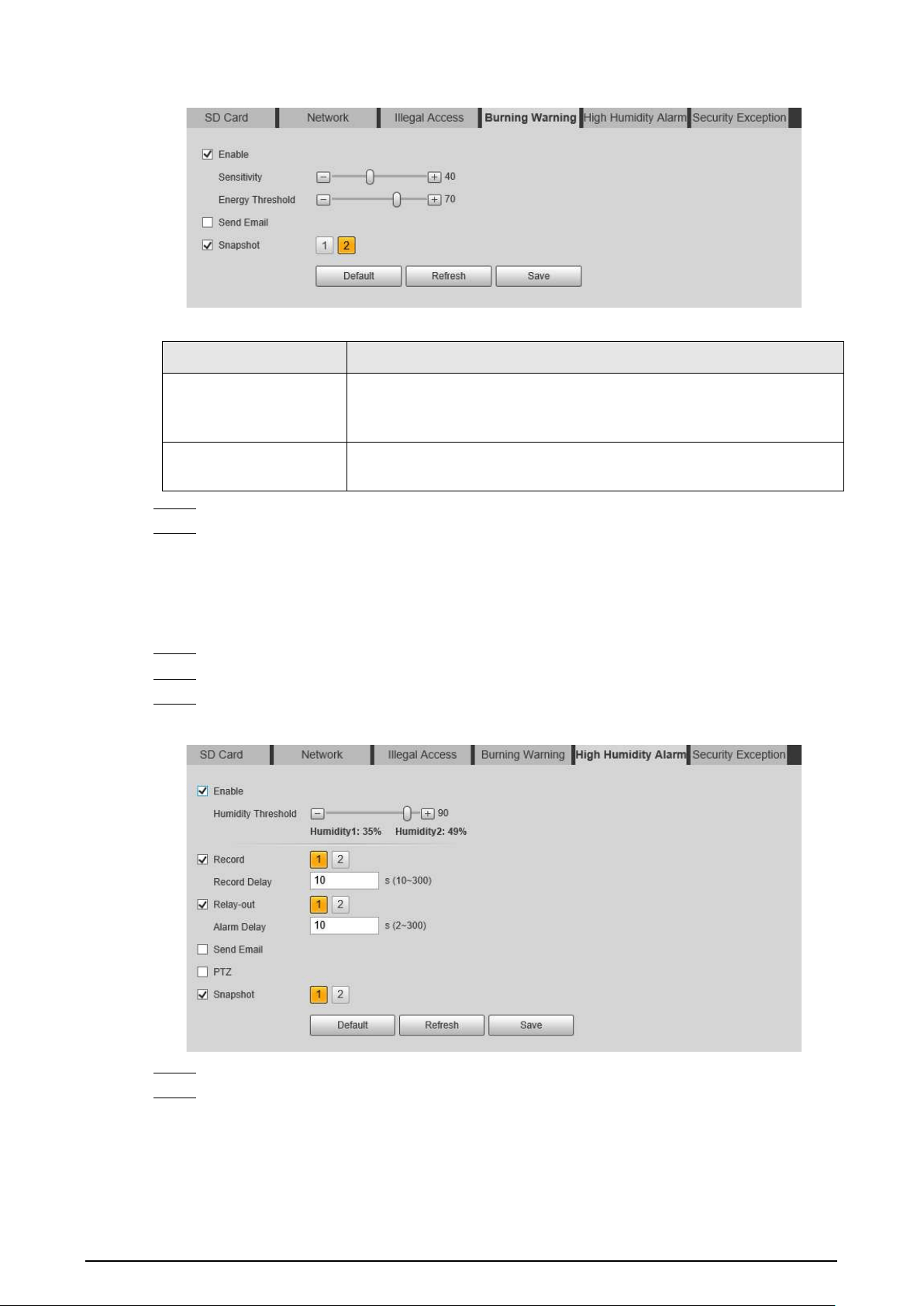
48
Figure 5-11 Burning warning
Table 5-2 Description of burning warning parameters
Parameter Description
Sensitivity
Sensitivity for the Camera to recognize whether the lenses are
watching towards the sun. The larger the value is, the easier the
Camera will be to recognize the sun.
Energy Threshold
Filters the targets with low temperature. The larger the value is, the
harder the alarm will be triggered.
Step 4 Set alarm linkage actions. For details, see "5.1.1 Alarm Linkage".
Step 5 Click
Save
.
5.1.6.5 Configuring High Humidity Alarm
When the humidity in the Camera is detected too high, the Camera performs alarm linkage actions.
Step 1 Select
Setting
>
Event
>
Abnormality
>
High Humidity Alarm
.
Step 2 Select the
Enable
checkbox.
Step 3 Set the humidity threshold.
Figure 5-12 High humidity alarm
Step 4 Set alarm linkage actions. For details, see "5.1.1 Alarm Linkage".
Step 5 Click
Save
.
5.1.6.6 Configuring Security Exception
When a hostile attack is detected, the Camera performs alarm linkage.

49
Step 1 Select
Setting
>
Event
>
Abnormality
>
Security Exception
.
Step 2 Select the
Enable
checkbox.
Step 3 Set the humidity threshold.
Figure 5-13 High humidity alarm
Step 4 Set alarm linkage actions. For details, see "5.1.1 Alarm Linkage".
Step 5 Click
Save
.
5.2 Temperature Measurement
This function is available on the models with the temperature measurement function.
5.2.1 Note
●
We recommend that the measuring distance is shorter than 50 m. Long-distance measurement
will affect the measurement accuracy because of the humidity and transmissivity of atmosphere,
reflection of the sun and heat source.
●
For small targets, we recommend you install the Camera facing to the target.
5.2.2 Configuration Flow
Figure 5-14 Configuration Flow
5.2.3 Configuring Thermal Image
Configure a specific scenario where you use the Camera, including indoor scenario, outdoor
scenario, and adaptive scenario. You can select a scenario as needed, and configure and check the
scenario.
Step 1 Select
Setting
>
Camera
>
Conditions
>
Conditions
.
Step 2 Select
2
in
Channel
.
Step 3 Select the scenario.
Select the image mode according to the environment. It is
Auto
by default.

50
We recommend you select
Low Dynamic
for indoor environment, and
High Dynamic
for
outdoor environment (stand out the details). When you select
High Dynamic
and the
details are not clear, you can adjust the threshold of
Sharpness
and
Detail Enhancement
,
but the noise will be larger.
Step 4 Select the colorization.
Figure 5-15 Thermal image page
Step 5 Configure advanced parameters.
Table 5-3 Description of Parameter lens
Classification Parameter Description
Basic Settings
Brightness
Changes the value to adjust the picture
brightness. The larger the value is, the
brighter the picture will be, and the smaller
the darker. The picture might be hazy if the
value is configured too large.
Contrast
Changes the contrast of the picture. The
larger the value is, the more the contrast will
be between bright and dark areas, and the
smaller the less. If the value is set too large,
the dark area would be too dark and bright
area easier to get overexposed. The picture
might be hazy if the value is set too small.
Sharpness
Changes the sharpness of picture edges. The
larger the value is, the clearer the picture
edges will be. If the value is set too large,
picture noises are more likely to appear.

51
Classification Parameter Description
Detail Enhancement
Stands out the details of the target. The
larger the value is, the more obvious the
details will be.
EZoom
Enlarges the thermal image according to the
zoom time that you have configured.
Mirror
Select
On
, and the picture will be displayed
with left and right side reversed.
Flip
Changes the display direction of the picture,
see the options below.
●
0°: Normal display.
●
90°: The picture rotates 90° clockwise.
●
180°: The picture rotates 90°
counterclockwise.
●
270°: The picture flips upside down.
For some models, please set the resolution
to be 1080p or lower when using 90° and
180°. For details, see "6.1.2 Configuring Video
Parameters".

52
Classification Parameter Description
Fusion Mode
Displays the image with the gray scale
information of the visible channel, and marks
temperatures with color palettes, which
makes the image of the thermal channel
clearer.
●
Original
: Displays the image of the
thermal channel.
●
Warm Color
: Combines the data of the
visible channel and the thermal channel,
and displays the image in warm color.
●
Cold Color
: Combines the data of the
visible channel and the thermal channel,
and displays the image in cold color.
●
Fusion Rate
: It ranges from 0 to 100. The
larger the value, the larger the proportion
of the visible channel.
●
Dual-lens Calibration Adjustment
: You
can adjust the misaligned images
through direction keys.
●
Speed
: The moving speed of the lens
when adjusting the image.
To get a better fusion effect, keep the
distance 3 m between the Camera and the
targets.
Image Enhancement
Basic NR (Noise
Reduction
Compares one frame to the next and
removes any oddity that does not appear in
each frame.
The larger the value is, the fuzzier the image
will be.
Advanced NR (Front
Module)
Removes the grainy fuzzy appearances of low
light images, will handle moving objects
without leaving tails behind, and in low light,
it makes an image clearer and sharper.
●
Advanced NR (Front Module): The
module handles noise reduction.
●
Advanced NR (Rear Chip): The back-end
program handles noise reduction.
Generally, you can select
Basic NR (Noise
Reduction)
and
Advanced NR (Front
Module)
. If the image is not clear, select
Advanced NR (Rear Chip)
, and configure
the parameters.
Advanced NR (Rear
Chip)

53
Classification Parameter Description
Agc settings
Auto Gain
The larger the gain value, the more unstable
the image.
Gain Mode
Low-temperature mode and high-
temperature mode are contained.
FFC Settings
FFC Mode
Method of correcting the shutter.
●
Auto: According to the switch period that
you have configured, the shutter will be
corrected regularly.
●
Manual: Correct the shutter by yourself.
FFC Period
You can configure this parameter only when
FFC Mode
is set to be
Auto
.
Adjust time gap of correcting the shutter
automatically.
Do FFC
Click
Do FFC
to trigger the shutter correcting
for this time.
Step 6 Click
Save
.
5.2.4 Configuring Burning Warning
When the lenses are watching directly towards the sun and face the potential burning, an alarm will
be triggered, and the Camera will automatically turn to other positions to avoid.
This function is available on select models.
Step 1 Select
Setting
>
Event
>
Abnormality
>
Burning Warning
.
Step 2 Select the
Enable
checkbox.
Step 3 Configure
Sensitivity
and
Energy Threshold
.
Figure 5-16 Burning warning
Table 5-4 Description of burning warning parameters
Parameter Description
Sensitivity
Sensitivity for the Camera to recognize whether the lenses are
watching towards the sun. The larger the value is, the easier the
Camera will be to recognize the sun.
Energy Threshold
Filters the targets with low temperature. The larger the value is, the
harder the alarm will be triggered.
Step 4 Set alarm linkage actions. For details, see "5.1.1 Alarm Linkage".

54
Step 5 Click
Save
.
5.2.5 Configuring Preset
Preset means a certain position that the Camera can make quick orientation to. It includes PTZ pan
and tilt angles, camera focus, and location.
Procedure
Step 1 Select
Setting
>
PTZ
>
Function
.
Figure 5-17 Preset
Step 2 Configure preset.
1) Click
Add
to add a new preset.
2) Operate the PTZ control panel to move the camera lens to a specific direction that you
need.
3) Double-click
Preset Title
to modify the title of the preset.
4) click .
Related Operations
●
Click to delete a preset.
●
Click
Delete
to delete all the presets that you have added.
5.2.6 Configuring Temperature Measurement Parameters
Configure temperature measurement rules and when alarm conditions are met, an alarm will be
triggered.
5.2.6.1 Configuring Temperature Measuring Rules
You can set multiple regular temperature measurement rules, including spot, line, polygon,
rectangle and ellipse. Based on the configured temperature measurement rules, you can calculate
the temperature of each spot according to the gray value of each pixel in the regular area, and the

55
maximum temperature, minimum temperature and average temperature will be displayed.
Step 1 Select
Setting
>
Temperature
>
Rule
>
Parameter
.
Figure 5-18 Parameter
Step 2 Configure temperature measurement parameters.
1) Select the preset.
2) Click to add a rule.
3) Double-click the added rule to select measurement items and edit the measurement
name.
4) Draw the rules.
Select
Measurement Items
as
Spot
, and you can click a position on the surveillance
image and a spot is formed.
Select
Measurement Items
as
Line
,
Rectangle
or
Ellipse
, and you can hold the left
mouse button to draw rules that you need on the surveillance image.
Select
Measurement Items
as
Polygon
, and you can hold the left mouse button to
draw rules that you need on the surveillance image. Right-click to end your drawing.
●
You can draw 12 rules at most.
●
Select a rule that you have drawn and click
Redraw Rule
. Then you can delete the
rule and draw a new one.
5) Select the
Open Local Config
checkbox and configure parameters.
Table 5-5 Description of local configuration parameter
Parameters Description
Target Radiation Coefficient
Radiation coefficient of targets that are shot by this Camera. It
ranges from 0.5 to 1.
Target Distance
Distance from the Camera to targets that are shot. It ranges
from 0 m to 10000 m.
Target Reflection
Temperature
Temperature of targets that are shot by this Camera. It ranges
from–50 °C to +327.7 °C.
6) Select the
Relay-out
checkbox and configure the parameters.

56
Table 5-6 Description of relay-out parameter
Parameter Description
Alarm Results
The display items of temperature.
●
Select
Measurement Items
as
Spot
, and average temperature
and temperature slope will be displayed.
●
Select
Measurement Items
as
Line
,
Rectangle
,
Ellipse
or
Polygon
, and maximum/minimum/average temperature,
temperature slope and temperature difference are displayed.
●
Temperature difference refers to the difference between
maximum and minimum temperatures under rules you have set.
●
Temperature slope refers to the change rate of the average
temperature with the configured rules.
Alarm Condition Set alarm conditions, covering
Below
,
Match
and
Above
.
Alarm Threshold
Temperature
It ranges from–40 °C to +550 °C.
You can set this value when you select
Alarm Results
as
Max
,
Min
,
Aver
, or
Temperature Difference
.
Temperature Slope
The temperature difference in each minute. Ranges from–
600 °C/min to +600 °C/min.
You can set this value when you select
Alarm Results
as
Slope
.
Temperature Error
Set a temperature error value and if the alarm threshold temperature
or temperature slope is within the value that you have set, alarms
will still be triggered. It ranges from–10 °C to +10 °C.
Duration of Temperature
You can set the duration of abnormal temperature after which
alarms will be triggered. It ranges from 0–1000 s.
Step 3 Click
Save
.
You can view temperature changes under the rules that you have configured.
5.2.6.2 Configuring Temperature Contrast
Compares temperature of the selected spots, lines or area and displays comparison results on the
live page.
Prerequisites
You have configured at least two temperature measurement rules. For details, see "5.2.6.1
Configuring Temperature Measuring Rules".
Procedure
Step 1 Select
Setting
>
Temperature
>
Rule
>
Temp Contrast
.
Step 2 Set temperature contrast rules
1) Click to add a temperature contrast rule.

57
Figure 5-19 Add temperature contrast rules
2) Double-click to add a temperature contrast rule.
3) Set alarm parameters.
Table 5-7 Description of temperature contrast parameters
Parameter Description
Alarm Results
You can select from the following three options to determine a
standard of triggering an alarm.
●
Average temperature: Compares average temperatures of two
rules.
●
Maximum temperature: Compares maximum temperatures of
two rules.
●
Minimum temperature: Compares minimum temperatures of
two rules.
When one of the two rules refers to a spot, both maximum
temperature and minimum temperature are actually average
temperature.
Alarm Condition Contains
Lower
,
Matched
and
Higher
.
Alarm Threshold
Temperature
Temperature of triggering an alarm. It ranges from 0–550 °C.
Step 3 Click
Save
.
On the live image, you can view temperature contrast results of the select objects.
5.2.6.3 Configuring Global Setup
After enabling the temperature measurement rules, the configured rules take effect, and the rules
are displayed on the live view.
Step 1 Select
Setting
>
Temperature
>
Global Setup
.
Step 2 Configure the global setup parameters.

58
Figure 5-20 Global setup
Table 5-8 Parameter description of global setup
Parameter Description
Temperature Switch Select the checkbox to enable this function.
Temperature Unit Includes °C and °F.
Relative Humidity Relative humidity of environment. Ranges from 0RH–100%RH.
Atmospheric Temperature
Temperature of our environment. Ranges from–50 °C to
327.7 °C.
Target Radiation Coefficient
Set Radiation coefficient of targets that are shot by this
Camera. Ranges from 0.5–1.
Target Distance
Distance from the Camera to targets that are shot. Ranges from
0 m–10,000 m.
Target Reflection Temperature
The temperature radiation of the objects around the target. It
reflects to the Camera through target surface to affect the test
results.
Advanced
Configure the Isotherm function as needed. For details, see
"5.2.9 Isotherm".
Step 3 Click
Save
.
Result
After successfully configuration, you can view the results on the live view.

59
Figure 5-21 Temperature switch
5.2.7 Configuring Temperature Alarm
When the temperature meets the defined alarm condition, an alarm is triggered and the Camera
performs alarm linkage.
Prerequisites
You have set the temperature measurement rules. See "5.2.6 Configuring Temperature
Measurement Parameters" for detailed operation.
This function is available on models with temperature measurement function.
Procedure
Step 1 Select
Setting
>
Event
>
Temperature Alarm
.
Step 2 Select the
Enable
checkbox.
Configure the threshold of temperature alarm in
Setting
>
Temperature
>
Rule
>
Parameter
. The Camera will perform alarm according to the configuration.

60
Figure 5-22 Temperature alarm
Step 3 Configure arming periods and alarm linkage action. For details, see "5.1.1 Alarm Linkage"
and "5.1.2 Setting Period".
Step 4 Click
Save
.
5.2.8 Verification
After configuration, enable
Temperature Alarm
,
Prompt
, and
Play Alarm Tone
. When an alarm is
triggered, the Camera prompts and records alarm according to the actual situation.
Step 1 Click the
Alarm
tab.
Step 2 Select
Temperature Alarm
.
Figure 5-23 Alarm

61
Step 3 (Optional) Select
Prompt
, and the system prompts and records alarm information as
needed.
●
If you are not on the
Alarm
page when alarm events that you have subscribed are
triggered, is displayed on the
Alarm
tab and the alarm information will be
recorded. Click the
Alarm
tab, and the sign disappears.
●
If you are on the
Alarm
page when the selected alarm is triggered, there will be
detailed alarm information displayed at the right side of the page.
Step 4 (Optional) Select the
Play Alarm Tone
checkbox, and select an audio file.
System would play the audio file that you have selected, when the subscribed alarm events
are triggered.
Click
Clear
to remove all the alarm information.
5.2.9 Isotherm
Stands out the temperature range of the image.
●
Isotherm: Used to highlight an object in images of high brightness. Isotherm is based on median
temperature, with highest temperature and lowest temperature as its range. The part of an
object whose temperature is higher than min limit temperature will be represented in a bright
color and the part of an object whose temperature is lower than min limit temperature will be
represented in a black/white color. After enabling Isotherm, you have to make sure that min limit
temperature <= max limit temperature <= ceiling temperature <= saturation temperature.
●
Color Code: Enable this function, and a color code is displayed on the right side of surveillance
images to show the change of color between minimum temperature and maximum temperature.
The Camera is equipped with a color palette. Different from the traditional palette, the palette can
correspond to the temperature, and different colors correspond to different temperature ranges.
Different temperature ranges are displayed in different colors, thus realizing the isotherm display
function. There are two types of palettes for displaying different temperatures. You can determine
which type of palette to use by the color bars in the image.
Colored palettes
All the colors in the selected palette are used to color the image, but they cannot highlight the
temperature. The vertical color bar in the image displays the selected palette.
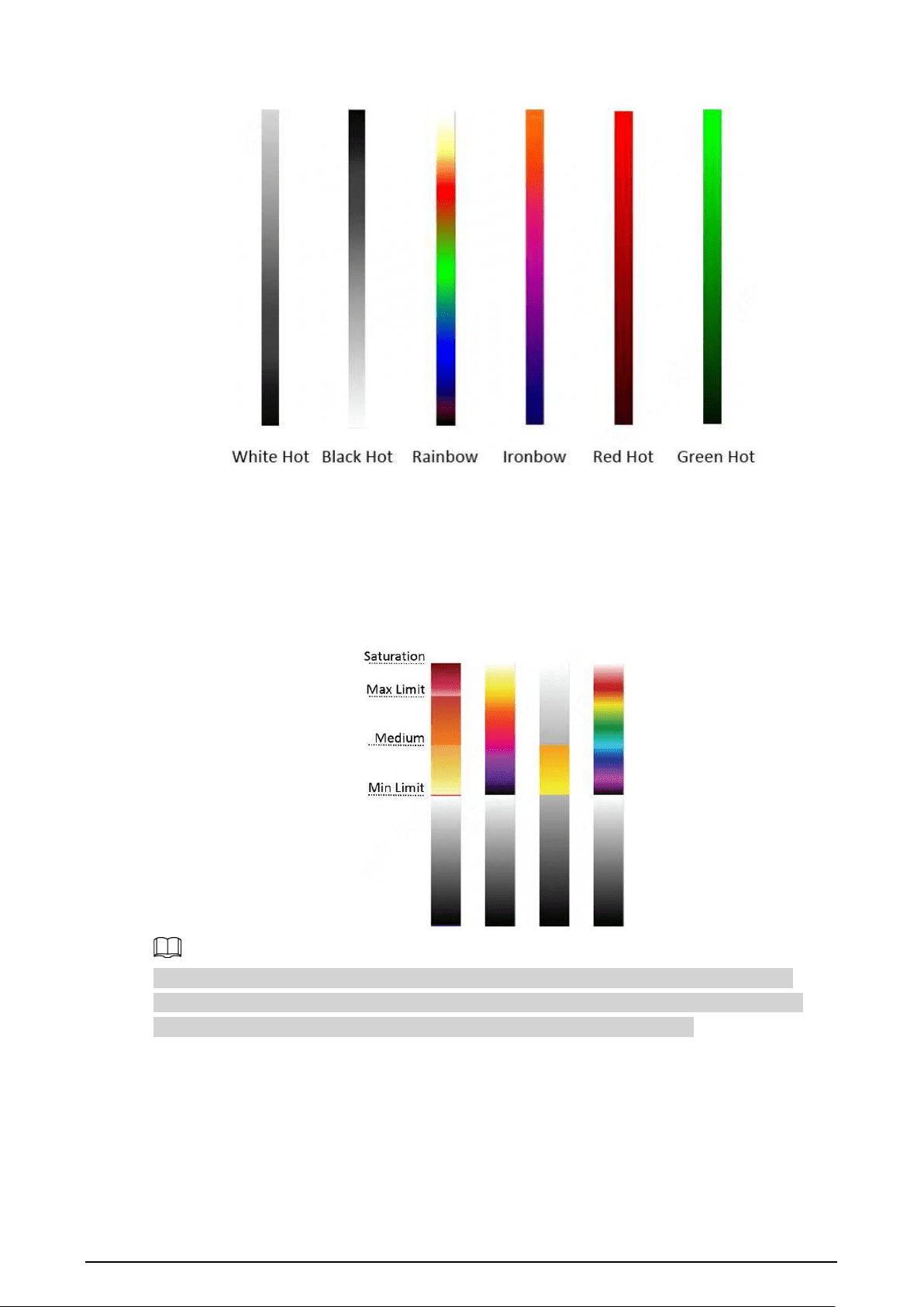
62
Figure 5-24 Colored palettes
Isotherm palettes
The isotherm palette can be used to isolate the predetermined temperature. The vertical color bar in
the image displays the selected palettes and the input temperature standard. When exceeding the
configured temperature standard, the target will be highlighted according to the configured color of
the tone.
Figure 5-25 Isotherm palettes
For example, you have configured temperature limit for the target, all areas with temperature
exceeding this configured threshold will be highlighted with specific colors. After receiving the
alarm, you can quickly determine the alarm source through the isotherm image.

63
Figure 5-26 Isotherm
5.3 Configuring IVS
5.3.1 Scene-Selecting Requirements
●
The target should occupy no more than 10% of the whole image.
●
The target size in the image should be no more than 10 × 10 pixels. The size of abandoned object
in the image should be no less than 15 × 15 pixels (CIF image). The target height and width
should be no more less than a third of the image height and width. The recommended target
height is 10% of the image height.
●
The brightness difference of the target and the background should be no less than 10 gray levels.
●
The target should be continuously present in the image for no less than 2 seconds, and the
moving distance should be larger than its width and no less than 15 pixels (CIF image) at the
same time.
●
Reduce the complexity of surveillance scene as much as you can. Intelligent analysis functions
are not recommended to be used in scene with dense targets and frequent illumination change.
●
Avoid areas such as glass, reflective ground, water surface, and areas interfered by branch,
shadow and mosquito. Avoid backlight scene and direct light. Control image proportion of
objects that are with high relative ambient temperature.
5.3.2 Configuration Flow
Figure 5-27 Configuration Flow

64
5.3.3 Configuring Preset
Preset means a certain position that the Camera can make quick orientation to. It includes PTZ pan
and tilt angles, camera focus, and location.
Procedure
Step 1 Select
Setting
>
PTZ
>
Function
.
Figure 5-28 Preset
Step 2 Configure preset.
1) Click
Add
to add a new preset.
2) Operate the PTZ control panel to move the camera lens to a specific direction that you
need.
3) Double-click
Preset Title
to modify the title of the preset.
4) click .
Related Operations
●
Click to delete a preset.
●
Click
Delete
to delete all the presets that you have added.
5.3.4 Configuring Smart Plan
You need to enable smart plan before intelligent rules function.
Step 1 Select
Setting
>
Event
>
Smart Plan
.

65
Figure 5-29 Smart Plan
Step 2 Select a preset in
Add Plan
.
A solution corresponding to presets is displayed.
Step 3 Click on the
Smart Plan
page.
You might need to disable other smart plans before enabling it.
●
The icon that you have selected will be lighted.
●
Click the icon again to cancel the smart plan.
Step 4 Click
Save
.
5.3.5 Configuring Intelligent Rules
Set rule for IVS, including tripwire and intrusion.
Background Information
For the functions and applications of the rules, see Table 5-9. This section uses configuring tripwire
as an example.
Table 5-9 Description of IVS functions
Rule Description Applicable Scene
Tripwire
When the target crosses tripwire from the
defined motion direction, an alarm is
triggered, and then the system performs
configured alarm linkages.
Scenes with sparse targets and
no occlusion among targets,
such as the perimeter
protection of unattended area.
Intrusion
When the target enters, leaves, or
appears in the detection area, an alarm is
triggered, and the system performs
configured alarm linkages.
Procedure
Step 1 Select
Setting
>
Smart Thermal
>
IVS
>
Rule Config
.
After entering the
Rule Config
page, the PTZ locking function is automatically enabled.

66
The locking time is 180 seconds. During the locking period, you can only control the PTZ
manually. Click
Unlock
at the lower-left corner of the
Rule Config
page to manually
unlock the PTZ. Click again after unlocking to re-lock the PTZ.
Figure 5-30 Rule configuration
Step 2 Select the channel.
●
Select
1
in
Channel
to configure the rule for the visible channel.
●
Select
2
in
Channel
to configure the rule for the thermal channel.
Step 3 Select the preset.
The preset with the smart plan enabled is green.
Step 4 Click to add a rule.
Step 5 Double-click the added rule to edit the rule name, and select
tripwire
as the type.
Step 6 Click
Draw Rule
to draw a rule line in the image. Right-click to finish drawing. After
finishing drawing, drag the ends of the line to adjust the detection areas.
●
Tripwire: Draw a detection line.
●
Intrusion: Draw a detection area.
Click
Clear
to delete the drawn rule.
Step 7 (Optional) Select
Max Size
or
Min Size
, click
Draw Target
, and then drag the corners of
the filter box to make the box larger or smaller.
Click
Clear
to delete all drawn detection lines.

67
Step 8 Configure the parameters.
Table 5-10 Description of IVS parameters
Parameter Description
Direction
Set the direction of rule detection.
●
When setting tripwire, select
A->B
,
B->A
, or
A<->B
.
●
When setting intrusion, select
Enter
,
Exit
, or
Both
.
Action
When setting intrusion action, select
Appears
or
Cross
.
Alarm tracking
Select
Alarm Tracking
to enable this function. When an alarm is triggered,
the Camera automatically tracks the person or object that triggers the alarm.
For details, see "5.3.7 Configuring Auto Tracking".
Track Time
Select
Alarm Track
and set the tracking time. When an alarm is triggered, the
Camera automatically tracks the person or object that triggers the alarm.
Tracking time is the duration that the Camera automatically tracks the object.
Target Filter
Select
Target Filter
to enable this function.
●
When you select
Human
as the alarm target, an alarm will be triggered
when the system detects persons triggering the rule.
●
When you select
Motor Vehicle
as the alarm target, alarm will be
triggered when the system detects vehicle triggering the rule.
Step 9 Configure arming periods and alarm linkage action. For details, see "5.1.1 Alarm Linkage"
and "5.1.2 Setting Period".
Step 10 Click
Save
.
If you want to view the alarm details on the
Alarm
page, subscribe alarm information. For
details, see "4.5.2 Subscribing Alarm Information".
5.3.6 Configuring Global Setup
Configure global rules for IVS. You can draw the detection area and exclusion areas. When the
configured rules are triggered in the detection areas (out of the exclusion areas), an alarm will be
triggered. For the thermal channel, you can also configure the sensitivity.
Procedure
Step 1 Select
Setting
>
Smart Thermal
>
IVS
>
Global Setup
.

68
Figure 5-31 Global setup
Step 2 Select the channel.
●
Select
1
in
Channel
to configure the rule for the visible channel.
●
Select
2
in
Channel
to configure the rule for the thermal channel.
Step 3 Select a preset in
Preset
bar.
The Camera turns to the position.
Step 4 Add detected area and excluded area.
1) Click
Add Detect Region
to draw a detected area on the image. Right-click to end
drawing.
Click
Add Detect Region
again to re-draw.
2) Click
Add Exclude Region
to draw an excluded area on the monitoring image. Right-
click to end drawing.
●
Click
Delete Excluded Area
to delete the excluded area.
●
An excluded area takes effect only when it has been drawn in the detected area.
●
Multiple excluded areas can be drawn in the detected area.
Step 5 Click
Save
.
5.3.7 Configuring Auto Tracking
When an alarm is triggered in the detection region, the Camera automatically tracks the target
triggering the alarm for a period.
Prerequisites
You have configured
Alarm Track
on the
Rule Config
page. For details, see "5.3.5 Configuring
Intelligent Rules".
Procedure
Step 1 Select
Setting
>
Smart Thermal
>
IVS
>
Auto Tracking
.
Step 2 Select the tracking mode as needed.
●
Visible Track/Thermal Track: Select
Visible Track
or
Thermal Track
.

69
Figure 5-32 Auto tracking (1)
●
Schedule: Select
Schedule
, and you can select the thermal or visible channel to track
the target as need in different periods. For example, you can select the visible channel
to track the target from 8:00 to 20:00, and the thermal channel to track the target from
20:01 to 8:00.
Figure 5-33 Auto tracking (2)
5.4 Call Detection
Configure call detection to help you monitor the calling behavior at locations such as gas stations.
Once a calling is detected, alarm will be triggered.
This function is only available on the visible channel.
5.4.1 Configuration Flow
Figure 5-34 Configuration Flow
5.4.2 Configuring Preset
Preset means a certain position that the Camera can make quick orientation to. It includes PTZ pan
and tilt angles, camera focus, and location.
Procedure
Step 1 Select
Setting
>
PTZ
>
Function
.

70
Figure 5-35 Preset
Step 2 Configure preset.
1) Click
Add
to add a new preset.
2) Operate the PTZ control panel to move the camera lens to a specific direction that you
need.
3) Double-click
Preset Title
to modify the title of the preset.
4) click .
Related Operations
●
Click to delete a preset.
●
Click
Delete
to delete all the presets that you have added.
5.4.3 Configure Smart Plan
You need to enable smart plan before intelligent rules function.
Step 1 Select
Setting
>
Event
>
Smart Plan
.
Figure 5-36 Smart Plan
Step 2 Select
1
in
Channel
.

71
Step 3 Select a preset in
Add Plan
.
A solution corresponding to presets is displayed.
Step 4 Click on the
Smart Plan
page.
You might need to disable other smart plans before enabling it.
●
The icon you have selected will be lighted.
●
Click the icon again to cancel the smart plan.
Step 5 Click
Save
.
5.4.4 Configure Call Detection
Configure the rule for calling in the visible channel. When a call action is detected, an alarm is
triggered., and then the Camera performs linkages actions.
Step 1 Select
Setting
>
Smart Thermal
>
Call Detection
.
Step 2 Select the preset.
The preset with the smart plan enabled is green.
Step 3 Click
Draw Rule
, drag the corners of the rectangle to adjust the detection areas.
●
The whole image is the detection area by default.
●
Click
Clear
to delete the drawn rules.
Figure 5-37 Rule configuration
Step 4 (Optional) Select
Max Size
or
Min Size
, click
Draw Target
, and then drag the corners of
the filter box to make the box larger or smaller.

72
Click
Clear
to delete all drawn detection lines.
Step 5 Select
Enable
, and then set the interval and sensitivity.
●
Interval: The time that calling behavior lasts. When the Camera detects the calling time
beyond the configured value, an alarm is triggered.
●
Sensitivity: The larger the value is, the more sensitive the call detection is. However,
setting the value too large might cause false alarm.
Step 6 Configure arming periods and alarm linkage action. For details, see "5.1.1 Alarm Linkage"
and "5.1.2 Setting Period".
Step 7 Click
Save
.
Result
According to the configured rules, when call action is detected in the detection area, an alarm is
triggered, and the Camera performs linkage actions.
Click the
Alarm
tab on the main page, and then select
IVS
. When an alarm is trigged, you can view
the details on the
Alarm
page.
5.4.5 Configuring Global Setup
Configure global rules for call detection. You can draw the detection area and exclusion areas. When
the configured rules are triggered in the detection areas (out of the exclusion areas), an alarm will be
triggered.
Procedure
Step 1 Select
Setting
>
Smart Thermal
>
Call Detection
>
Global Setup
.
Step 2 Select the preset.
The preset with the smart plan enabled is green.
Figure 5-38 Global setup
Step 3 Add detected area and excluded area.
1) Click
Add Detect Region
to draw a detected area on the image. Right-click to end

73
drawing.
Click
Add Detect Region
again to re-draw.
2) Click
Add Exclude Region
to draw an excluded area on the monitoring image. Right-
click to end drawing.
●
Click
Delete Exclude Region
to delete the excluded area.
●
An excluded area takes effect only when it has been drawn in the detected area.
●
Multiple excluded areas can be drawn in the detected area.
Step 4 Click
Save
.
5.5 Smoking Detection
Configure global rules for smoking detection. You can draw the detection area and exclusion areas.
When the configured rules are triggered in the detection areas (out of the exclusion areas), an alarm
will be triggered.
This function is only available on the thermal channel.
5.5.1 Configuration Flow
Figure 5-39 Configuration Flow
5.5.2 Configuring Preset
Preset means a certain position that the Camera can make quick orientation to. It includes PTZ pan
and tilt angles, camera focus, and location.
Procedure
Step 1 Select
Setting
>
PTZ
>
Function
.

74
Figure 5-40 Preset
Step 2 Configure preset.
1) Click
Add
to add a new preset.
2) Operate the PTZ control panel to move the camera lens to a specific direction that you
need.
3) Double-click
Preset Title
to modify the title of the preset.
4) click .
Related Operations
●
Click to delete a preset.
●
Click
Delete
to delete all the presets that you have added.
5.5.3 Configure Smart Plan
You need to enable smart plan before intelligent rules function.
Step 1 Select
Setting
>
Event
>
Smart Plan
.
Figure 5-41 Smart Plan
Step 2 Select
2
in
Channel
.

75
Step 3 Select a preset in
Add Plan
.
A solution corresponding to presets is displayed.
Step 4 Click the icon on the
Smart Plan
page.
You might need to disable other smart plans before enabling it.
●
The icon you have selected will be lighted.
●
Click the icon again to cancel the smart plan.
Step 5 Click
Save
.
5.5.4 Configure Smoking Detection
Configure the rule for smoking detection in the thermal channel. When a smoking action is detected,
an alarm is triggered., and the system performs linkages such as recording, alarm output, sending
email, and snapshot.
Step 1 Select
Setting
>
Smart Thermal
>
Smoking Detection
.
Step 2 Select the preset.
The preset with the smart plan enabled is green.
Step 3 Click
Draw Rule
, drag the corners of the rectangle to adjust the detection areas.
●
The whole image is the detection area by default.
●
Click
Clear
to delete the drawn rules.
Figure 5-42 Rule configuration
Step 4 (Optional) Select
Max Size
or
Min Size
, click
Draw Target
, and then drag the corners of
filter box to make the box larger or smaller.

76
Click
Clear
to delete all drawn detection lines.
Step 5 Select
Enable
, and then set the interval and sensitivity.
●
Interval: The time that calling behavior lasts. When the Camera detects the calling time
beyond the configured value, an alarm is triggered.
●
Sensitivity: The larger the value is, the more sensitive the call detection is. However,
setting the value too large might cause false alarm.
Step 6 Configure arming periods and alarm linkage action. For details, see "5.1.1 Alarm Linkage"
and "5.1.2 Setting Period".
Step 7 Click
Save
.
Result
According to the configured rules, when call action is detected in the detection area, an alarm is
triggered, and the Camera performs linkage actions.
Click the
Alarm
tab on the main page, and then select
IVS
. When an alarm is trigged, you can view
the details on the
Alarm
page.
5.5.5 Configuring Global Setup
Configure global rules for smoking detection. You can draw the detection area and exclusion areas.
When the configured rules are triggered in the detection areas (out of the exclusion areas), an alarm
will be triggered.
Procedure
Step 1 Select
Setting
>
Smart Thermal
>
Smoking Detection
>
Global Setup
.
Step 2 Select the preset.
The preset with the smart plan enabled is green.
Figure 5-43 Global setup
Step 3 Add detected area and excluded area.
1) Click
Add Detect Region
to draw a detected area on the image. Right-click to end
drawing.

77
Click
Add Detect Region
again to re-draw.
2) Click
Add Exclude Region
to draw an excluded area on surveillance image. Right-click
to end drawing.
●
Click
Delete Exclude Region
to delete the excluded area.
●
An excluded area takes effect only when it has been drawn in the detected area.
●
Multiple excluded areas can be drawn in the detected area.
Step 4 Click
Save
.
5.6 Boat Detection
Detects boats in the detection area, and detects the boat parameters such as speed, height and
distance. After configuring the rule, when a boat is detected crossing the rule line or area, an alarm is
triggered, and the Camera performs linkage actions.
5.6.1 Note
●
Install the Camera (with looking down) on a high point to avoid obstruction in the scanning
range and direct sunlight. Ensure that there is no interference during device rotation and
pitching. The recommended installation height is 10-40 m.
●
We recommend angle steel tower for tower mount. Install the Camera on the top of the tower to
avoid the obstruction from the tower. When installing on the side, the iron tower/wall will cause
a detection blind area, which is not conducive to boat detection.
●
The Camera should be installed horizontally to avoid the slope of the base, to ensure the
accurate calibration function of the boat. We recommend you use two nuts and spring washers
at each hole of the PTZ to make the tower steady, so that the Camera keeps horizontal.
●
Make sure that the mounting surface can sustain at least 8 times the weight of the Camera and its
mounting structural components. The heavy PTZ (the weight of bare machines is about 40–70
kg) should be installed on the installation plane that can sustain more than 1 T weight.
5.6.2 Configuration Flow
Figure 5-44 Configuration Flow
5.6.3 Configuring Preset
Preset means a certain position that the Camera can make quick orientation to. It includes PTZ pan
and tilt angles, camera focus, and location.

78
Procedure
Step 1 Select
Setting
>
PTZ
>
Function
.
Figure 5-45 Preset
Step 2 Configure preset.
1) Click
Add
to add a new preset.
2) Operate the PTZ control panel to move the camera lens to a specific direction that you
need.
3) Double-click
Preset Title
to modify the title of the preset.
4) click .
Related Operations
●
Click to delete a preset.
●
Click
Delete
to delete all the presets that you have added.
5.6.4 Configure Smart Plan
You need to enable smart plan before intelligent rules function.
Step 1 Select
Setting
>
Event
>
Smart Plan
.

79
Figure 5-46 Smart Plan
Step 2 Select a preset in
Add Plan
.
A solution corresponding to presets is displayed.
Step 3 Click on the
Smart Plan
page.
You might need to disable other smart plans before enabling it.
●
The icon you have selected will be lighted.
●
Click the icon again to cancel the smart plan.
Step 4 Click
Save
.
5.6.5 Configuring Boat Detection
Configure tripwire and intrusion and the linked actions.
Procedure
Step 1 Select
Setting
>
Smart Thermal
>
Boat Detection
>
Boat Detection
.
Step 2 Select a preset.
Step 3 Add a detection rule. For details, see "5.3.5 Configuring Intelligent Rules".
●
Tripwire: We recommend you select
Both
in
Direction
.
●
Intrusion: This is the common function of boat detection. When setting the detection
range, adjust the detection box to make it fit and cover the detection basin, to reduce
false alarms caused by objects on the shore.
Step 4 Filter targets.
In the closed fishing project, 3-10 m fishing boats are usually used for illegal fishing, and
the size of the target boat is relatively fixed. Using the target filtering function can reduce
the false alarm caused by large boats passing normally.
Click
Draw Target
next to
Target Filter
to draw the filtering box for this rule on the image.
Draw the filter box according to the actual boat size in the image. The target boat size is
between the maximum size and the minimum size.

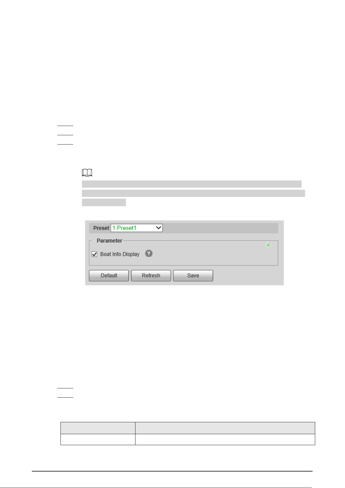
81
Result
According to the configured rules, when a boat is detected crossing the rule line or area, an alarm is
triggered, and the Camera performs linkage actions.
Click the
Alarm
tab on the main page, and then select
IVS
. When an alarm is trigged, you can view
the details on the
Alarm
page.
5.6.6 Configuring Global Setup
Enable the
Boat Info Display
function on the
Global Setup
page.
Step 1 Select
Setting
>
Smart Thermal
>
Boat Detection
>
Global Setup
.
Step 2 Select a preset.
Step 3 Select the
Boat Info Display
checkbox, and configure the sensitivity.
Boat information such as length, height, distance and speed will be displayed on the live
page.
Make sure that you have finished boat calibration; otherwise boat information such as
length, height, distance and speed are displayed as 0. For details, see "5.6.7 Configuring
Boat Calibration".
Figure 5-49 Global setup
5.6.7 Configuring Boat Calibration
According to calibrated ruler and its corresponding actual distance, determines the relationship
between the two-dimensional image obtained by the device and the three-dimensional real object.
Prerequisites
Before calibration, make sure that you have selected the reference object with known length and
parallel to the ground.
Procedure
Step 1 Select
Setting
>
Smart Thermal
>
Boat Detection
>
Global Calibration
.
Step 2 Select a calibration object, and configure the parameters.
1. Configure the installation height, calibration distance, and calibration object length.
Table 5-11 Parameter description
Parameter Description
Installation Height The distance between the Camera and the ground.

82
Parameter Description
Calibration Distance The distance between the Camera and the calibration object.
Calibration Object Length
The length of the object to be calibrated.
The calibration object can be a boat or any object on the horizontal
plane with known length.
2. Click .
3. Calibrate on the image.
Calibrate the objects with known length from beginning to end.
●
We recommend you add 8 pieces of calibration data.
●
For Camera without zoom function, use a horizontal line to draw the calibration
object from beginning to end to calibrate 8 pieces of data; for Camera with zoom
function, draw the calibration object from beginning to end with the different zoom
rates to calibrate 8 pieces of data.
Figure 5-50 Boat calibration
Step 3 Click
Save
.
5.7 Configuring Heat Warning
This function should be used with PTZ pan, and the coverage area is area that the thermal channel
covers.
5.7.1 Note
●
Install the Camera (with looking down) on a high point to avoid obstruction in the scanning
range and direct sunlight. Ensure that there is no interference in device rotation and pitching.
The recommended installation height is 10-40 m.
●
We recommend angle steel tower for tower mount. Install the Camera on the top of the tower to

83
avoid the obstruction from the tower. When installing on the side, the iron tower/wall will cause
a detection blind area, which is not conducive to heat detection.
●
The Camera should be installed horizontally to avoid the slope of the base, to ensure the
accurate calibration function of the heat point. We recommend you use two nuts and spring
washers at each hole of the PTZ to make the tower steady, so that the Camera keeps horizontal.
●
Make sure that the mounting surface can sustain at least 8 times the weight of the Camera and its
mounting structural components. The heavy PTZ (the weight of bare machines is about 40–70
kg) should be installed on the installation plane that can sustain more than 1T weight.
5.7.2 Configuration Flow
Figure 5-51 Configuration Flow
5.7.3 Configuring North
The north orientation of PTZ will affect the heat point positioning accuracy of the platform. The
Camera supports automatic north orientation and manual north orientation.
Step 1 Select
Setting
>
Camera
>
Video
>
Overlay
.
Step 2 Select
1
in
Channel
.
Step 3 Click
OSD Info
.
Figure 5-52 OSD Info
Step 4 Select the
Enable
checkbox of
North
, and then configure north.
●
Auto: Select
Auto
, and then click . The Camera rotates automatically. Click
Save
after

84
the Camera stops rotation.
●
Manual: Rotate the Camera lens to the north, select
Manual
, and then click .
Step 5 Verify North.
1. On the
Live
page, rotate the PTZ to any place, and then click
Go to
.
2. Enter 0 in
Horizontal Angle
and
Vertical Angle
.
3. Click
Go to
.
The Camera lens rotates to the North.
Figure 5-53 Verification
5.7.4 Configuring Burning Warning
When the lenses are watching directly towards the sun and face the potential burning, an alarm will
be triggered, and the Camera will automatically turn to other positions to avoid.
This function is available on select models.
Step 1 Select
Setting
>
Event
>
Abnormality
>
Burning Warning
.
Step 2 Select the
Enable
checkbox.
Step 3 Configure
Sensitivity
and
Energy Threshold
.
Figure 5-54 Burning warning
Table 5-12 Description of burning warning parameters
Parameter Description
Sensitivity
Sensitivity for the Camera to recognize whether the lenses are
watching towards the sun. The larger the value is, the easier the
Camera will be to recognize the sun.

85
Parameter Description
Energy Threshold
Filters the targets with low temperature. The larger the value is, the
harder the alarm will be triggered.
Step 4 Set alarm linkage actions. For details, see "5.1.1 Alarm Linkage".
Step 5 Click
Save
.
5.7.5 Configuring Pan
Enable pan, the Camera can realize continuous 360° horizontal rotation at a certain speed.
●
The interval between pan circles should not be lower than the default value. High PTZ speed
might cause missing alarm (see the table below for PTZ speed and time). The coverage area is
area that the thermal channel covers. The recommended speeds offer reference for heat
detection only; for smoke detection, make sure that the picture is not blurred during pan.
Table 5-13 PTZ speed and time
Device PTZ speed Time
Hybrid speed dome camera,
mobile hybrid PTZ camera,
multi-spectral PTZ camera
20 3'45"
30 (recommended) 2'30"
40 1'52"
Heavy PTZ camera
8 4'
10 (recommended) 2'25"
12 1'40"
●
If you do not set limits, the PTZ can continuously pan 360°. We recommend you use 360°
horizontal scanning for the forest fire prevention project. Multiple 360° pan circles can be set to
cover the area to be detected.
●
Set the left and right limits, and the PTZ pans between the limits.
●
Set the scanning area, the PTZ does progressive scanning in the configured area.
Figure 5-55 Auto adding
Step 1 Select
Setting
>
PTZ Function
>
Pan
.
Step 2 Click the direction button to adjust the camera angle.
Step 3 Click
Add
to add a circle on the current angle. Double-click the name, speed, interval time
or sensitivity to edit the corresponding content. Select the checkbox under
Left/Right
Limit
to enable and set the left and right limits for the current cycle; select the checkbox
under
Focus
to enable the focus function. Click to save the configuration.
●
Automatic adding: Add a pan circle at the top and bottom of the detection area

86
respectively, click , and then click
Auto Add
. The Camera automatically generates
the pan circles between the two configured pan circles, covering the part between the
top and bottom pan circles. This function is only available on some models.
●
Generally, 30° pitch angle from far to near can cover most of the detection area.
Configure it as needed.
●
The pan circle at the top of the detection area is close to the horizon to avoid exposing
the sky (to avoid sun burns). If there are hills, mountains and other areas higher than
the horizon that need to be scanned, you need to add more circles, and set the left and
right limits of single circle to cover them.
Step 4 (Optional) Set limits for PTZ.
The left and right limits are generally used to remove invalid areas such as the sky, to
improve the inspection efficiency and reduce the risk of direct sunlight.
●
Set left and right limit
When there are towers or walls that do not need to be scanned, you can set left and
right limits for scanning.
1. Select
Left/Right Limit
.
2. Click the direction button to rotate the camera lens to the left limit, and then click
Set Left Limit
.
3. Click the direction button to rotate the camera lens to the right limit, and then click
Set Right Limit
.
Figure 5-56 Global setting

87
Figure 5-57 Circle setting
●
Set area scanning
When you want the Camera to scan the specified area, you can set the area scanning.
1. Select
Area Scanning
.
2. Click the direction button to rotate the camera lens to the upper limit, and then click
Set Upper Limit
.
3. Click the direction button to rotate the camera lens to the lower limit, and then click
Set Lower Limit
.
4. Click the direction button to rotate the camera lens to the left limit, and then click
Set Left Limit
.
5. Click the direction button to rotate the camera lens to the right limit, and then click
Set Right Limit
.
Step 5 Select the configured pan path, and then click
Start
.
Click
Stop
to stop the pan.
5.7.6 Configuring Heat
When the Camera detects a heat point, an alarm is triggered and then the Camera performs linkage
actions. Heat mode includes preset and space excluded area.
Step 1 Select
Setting
>
Smart Thermal
>
Heat
>
Heat
.
Step 2 Select
2
in
Channel
.
Step 3 Select the heat mode, and configure the rule.
Space Excluded Area
is recommended.

88
Figure 5-58 Heat
●
Space Excluded Area
: Detects heat point during the PTZ rotation. This is the
recommended.
1. Select
Space Excluded Area
in
Heat Mode
.
2. Select the
Enable
checkbox.
3. Set the parameters.
◇
Mode
: When you select
Anti-jamming
, the Camera detects the suspected heat
point several times. The detection accuracy is higher, but the detection speed is
lower. When you select
High Response
, and the Camera detects heat point
quickly, but the detection accuracy is lower.
◇
Heat Point Wait Mode
: When you select
Auto
and set the stay time to be 25 s,
the PTZ stops working when a heat alarm is triggered, and will recover the
operations after the alarm duration (25 s). When you select
Manual
, the PTZ
stops working when a heat alarm is triggered, and will not recover the
operations after the alarm duration.
◇
Second Check After
: Only one alarm is triggered by the same alarm source in
the configured duration.
◇
Sensitivity
: The sensitivity of heat detection. The larger the value is, the higher
the sensitivity is. We recommended 75–90. We recommend you track and test
the value for a period, and adjust it according to the actual situation.

89
Heat point warning mode (
Anti-jamming
or
High Response
) is available for all
detection areas.
4. Set the shield area, and its sensitivity.
Manually configure shield areas to filter fixed false alarm sources, such as the
chimney in residential area, family stove and other areas. In addition, high engine
temperature might also cause false alarm in the areas where vehicles pass, such as
roads, parking lots, gas stations, and these false alarms can also be filtered by
setting shield areas. You can select default mode or compatibility mode for shield
area, and both modes can take effect at the same time.
◇
Click to add shield areas, and you can add 255 areas at most.
◇
Click to delete the shield area.
●
Preset
: Detects heat points on the preset.
1. Select
Preset
in
Heat Mode
.
2. Select the configured preset.
The camera lens rotates to the select preset.
3. Select the
Enable
checkbox.
4. Select the heat point warning mode as needed.
When you select
Anti-jamming
, the Camera detects the suspected heat point
several times. The detection accuracy is higher, but the detection speed is lower.
When you select
High Response
, and the Camera detects heat point quickly, but
the detection accuracy is lower.
Heat point warning mode is available for all detection areas. If you want the PTZ to
detect heat point during the rotation, select
Anti-jamming
.
5. Select a color in , set the area name and sensitivity, and then drag the
mouse on the image.
◇
The higher the sensitivity is, the easier a heat alarm will be triggered.
◇
The whole image is the detection area by default. You can draw multiple
detection areas.
Step 4 Configure arming periods and alarm linkage action. For details, see "5.1.1 Alarm Linkage"
and "5.1.2 Setting Period".
Step 5 Click
Save
.
5.7.7 Configuring Smoke Detection
5.7.7.1 Configuring Rule
After configuring smoke detection rule, when the visible channel detects smoke, an alarm is
triggered, and the system performs linkages such as recording, alarm output, sending email, audio,
alarm light, and snapshot.
Step 1 Select
Setting
>
Smart Thermal
>
Heat
>
Heat
.
Step 2 Select
1
in
Channel
.

90
Step 3 Select the
Enable
checkbox.
Step 4 Configure arming periods. For details, see "5.1.2 Setting Period".
Smoke detection is not supported at night.
Step 5 Configure the parameters.
●
Smoke Confirming Time
: Time for confirming suspected smoke. For example, if you
set the smoke confirming time to be 10 seconds, the PTZ will stop and confirm for 10 s
when the camera detects suspected smoke during rotation. If it is smoke, the visible
channel will confirm the target for the second time; if it is not smoke, the PTZ will
continue to operate as the configured mode.
●
Smoke Waiting Mode
: When you select
Auto
, and set the
Duration Time
to be 10 s,
the PTZ will stop scanning and alarm for 10 s when visible channel detects smoke, and
then automatically continues scanning; When you select
Manual
, you need to click
Continue
on the
Live
page to continue the pan.
●
Sensitivity
: Configure the sensitivity according to the actual situation. We recommend
you track and test the value for a period, and adjust it according to the actual situation
(the higher the value, the easier the smoke will be detected.).
●
Leave the advanced parameters as defaults.
Step 6 Click
Add
in
Region
, and draw an area on the image.
Figure 5-59 Smoke detection
The smoke detection exclusion area is mainly used to filter fixed false alarm sources such as
factory chimneys.
You can filter false alarm sources through setting target size. For details, see Step4 in "5.5.4
Configure Smoking Detection".
●
You can draw 32 exclusion areas (yellow) at most, and 6 areas for each single image.
●
You need to draw the exclusion areas on the visible channel.
●
Make sure that the drawn rectangle is 1.2 times of the target size.
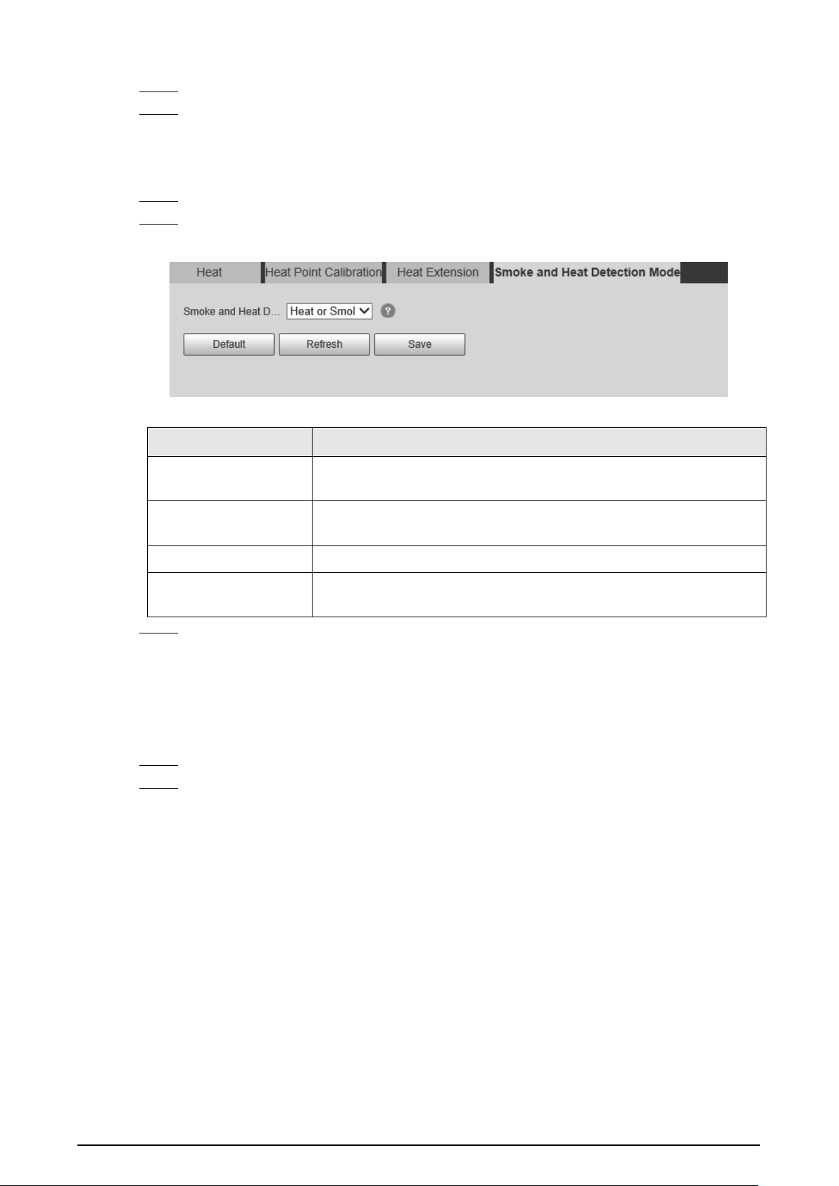
91
Step 7 Configure alarm linkage action. For details, see "5.1.1 Alarm Linkage".
Step 8 Click
Save
.
5.7.7.2 Configuring Smoke and Heat Detection Mode
Step 1 Select
Setting
>
Smart Thermal
>
Heat
>
Smoke and Heat Detection Mode
.
Step 2 Select the smoke and heat detection mode. We recommend you select
Heat or Smoke
.
Figure 5-60 Smoke and heat detection mode
Table 5-14 Parameters of smoke and heat detection mode
Parameter Description
Heat or Smoke
When the visible channel detects smoke or the thermal channel
detects heat point, an alarm will be triggered.
Heat Only
When the thermal channel detects heat point, an alarm will be
triggered.
Smoke Only When the visible channel detects smoke, an alarm will be triggered.
Heat and Smoke
When the visible channel detects smoke and the thermal channel
detects heat point at the same time, an alarm will be triggered.
Step 3 Click
Save
.
5.7.7.3 Verification
After configuration, enable
Heat
,
Prompt
, and
Play Alarm Tone
. When an alarm is triggered, the
Camera prompts and records alarm according to the actual situation.
Step 1 Click the
Alarm
tab.
Step 2 Select
Heat
.

92
Figure 5-61 Alarm
Step 3 (Optional) Select
Prompt
, and the system prompts and records alarm information as
needed.
●
If you are not on the
Alarm
page when alarm events you have subscribed are triggered,
is displayed on the
Alarm
tab and the alarm information will be recorded. Click the
Alarm
tab, and the sign disappears.
●
If you are on the
Alarm
page when the selected alarm is triggered, there will be
detailed alarm information displayed at the right side of the page.
Step 4 (Optional) Select the
Play Alarm Tone
checkbox, and select audio file.
System would play the audio file you have selected, when alarm events you have
subscribed are triggered.
Click
Clear
to remove all the alarm information.
5.7.8 Configuring Idle Motion
Idle motion means that the PTZ camera implements the operation which is configured in advance
when it does not receive any valid command within the set time.
You have configured preset, tour, scan and pattern before configuring idle motion.
Procedure
Step 1 Select
Setting
>
PTZ
>
Function
>
Idle Motion
.

93
Figure 5-62 Idle motion
Step 2 Configure idle motion.
1) Select the
Enable
checkbox to enable this function.
2) Select an idle motion and set idle time.
3) Click
Save
.
5.7.9 Configuring Heat Point Calibration
Find the obvious point according to the installation position of the Camera, and then set the
reference point and the calibration point. It is convenient to calculate the GPS position of heat point
through the heat point location algorithm in case of fire in the future. This function should be used
with a platform.
Prerequisites
●
Select a point or object that can be easily identified on the ground as a reference point.
●
When configuring reference points and calibration points, make sure that the camera resolution
is consistent with the resolution of the device in use.
●
During deployment, select four orientations to add reference points respectively (each reference
point can be configured with up to five calibration points). The more points are added, the more
accurate the heat point positioning is.
Procedure
Step 1 Select
Setting
>
Smart Thermal
>
Heat
>
Heat Point Calibration
.
Step 2 Add a reference point.
1. Click in
Reference Point
.
2. Select the visible channel, and then click the direction button to rotate the camera lens
to the reference point.
3. Double-click the reference point name, longitude, latitude and attitude to edit the
corresponding content, and then click .

94
Figure 5-63 Add reference point
Step 3 Add a calibration point.
You can select the same reference point, rotate the PTZ (so that the reference points are at
different positions on the image), and then calibrate multiple calibration points.
1. Select the added reference point in the
Calibration Point
.
2. Click in
Calibration Point
.
3. Rotate the camera lens. Make sure that all reference points are on the image.
4. Mark the positions of reference points on both visible and thermal channels.
5. Click
Calibration Confirmed
.
The calibrated point is displayed in the list of
Calibration Point
.
Figure 5-64 Add calibration point
Step 4 Repeat Step1–Step3 to add multiple reference points and calibration points.
After modifying the reference points, the corresponding calibration points will be cleared.

95
5.7.10 Configuring Heat Extension
Configure the snapshot type and times when the Camera detects a heat point. This function should
be used with a platform.
Step 1 Select
Setting
>
Smart Thermal
>
Heat
>
Heat Extension
.
Step 2 Configure the parameters.
Figure 5-65 Smoke detection
Step 3 Click
Save
.
5.8 Configuring Hot Trace
After enabling
Cold Hot Spot
, spot with the highest temperature and spot with the lowest
temperature are displayed with different colors.
Step 1 Select
Setting
>
Smart Thermal
>
Hot Trace
.
Step 2 Select the
Enable
checkbox.
The pages might vary according to different models.
Figure 5-66 Hot trace (Security)

96
Figure 5-67 Hot trace (Radiometry)
Step 3 Configure the parameters.
Table 5-15 Parameters of hot trace
Parameters Description
Color Mode
Select a color for cold and hot spots.
●
Auto: The hot spot color is red, and the cold spot color is blue by
default.
●
Manual: You can customize the colors for the hot spot and cold
spot.
Alarm Condition
Conditions under which an alarm is triggered.
●
Single
◇
Select the
Hot Spot temperature more than
checkbox and
when the highest temperature is larger than the configured
temperature, an alarm is triggered.
◇
Select the
Cold Spot temperature less than
checkbox and
when the lowest temperature is smaller than the configured
temperature, an alarm is triggered.
◇
If you select both conditions above at one time, an alarm is
triggered once any one condition is satisfied.
●
Combination
●
Only when the highest temperature is larger and the lowest
temperature is smaller than the configured temperature, an
alarm is triggered.
Anti-Dither Only one event is recorded within the time that you have set.
Step 4 Configure arming periods and alarm linkage action. For details, see "5.1.1 Alarm Linkage"
and "5.1.2 Setting Period".
Step 5 Click
Save
.
You can view the effect of hot trace on the
Live
page.

97
5.9 Configuring Pic in Pic
Overlays the thermal image on the visible image.
Step 1 Select
Setting
>
Smart Thermal
>
Pic in Pic
.
Figure 5-68 Pic in pic
Step 2 Select the
Enable
checkbox.
Step 3 Drag the corners the blue box to enlarge the box. Drag the box to adjust the its location.
Step 4 Click
Save
.
5.10 Configuring Link Schedule
The hybrid linkage (
Quick Focus
) of PTZ linkage only takes effect in the configured period.
Step 1 Select
Setting
>
Smart Thermal
>
Link Schedule
.
Figure 5-69 Link schedule
Step 2 Click
Setting
next to a day.
Step 3 Select a time period to be enabled.
Step 4 Enter start time and end time of a time period.
●
You can set 6 time periods per day.
●
Select
All
or checkboxes of some days to set the time period of multiple days at one
time.

98
Figure 5-70 Period
Step 5 Click
Save
.
The
Link Schedule
is displayed.
Step 6 Click
Save
.
5.11 Configuring Thermal Map Acquisition
Gets temperature of every pixel on thermal images, and you can export the heat map.
Step 1 Select
Setting
>
Smart Thermal
>
Thermal Map Acquisition
.
Figure 5-71 Thermal map acquisition
Step 2 Configure the parameters.
●
Frame
: The frame of the thermal map that you can acquire.
●
Get Mode
◇
Single Frame
: Acquires thermal map by single frame. There is interval between the
previous frame and next frame.
◇
Continuous
: Acquires thermal map by continuous frame. There is no interval
between the previous frame and next frame.
Step 3 Export
Export heatMap
.
Gets the grayscale data and the data file required for temperature calculation according to
a certain format, and analyzes and calculates the thermal image data through a special
thermal imaging analysis tool on the PC to obtain the heat map and calculate the
temperature of each pixel in the image. By analyzing the heat map, the functions such as
temperature measurement according to the configured rules, temperature proportion
statistics, temperature alarm, isotherm, pseudo color can be realized.
Thermal map files will be saved under the path that you have configured. For details, see

99
"6.1.2.5 Configuring Storage Path".
5.12 Configuring Fusion Calibrate
Calibrate the relative position between the thermal channel and the visible channel. If you want to
use the function of engineering truck filtering or reflective filtering, do fusion calibration first.
5.12.1 Note
●
Before calibration, disable the digital zoom and heat alarm functions, and stop all PTZ operations;
otherwise, changes in the scene might impact the calibration results.
●
Select a scene with various features.
●
When you switch to the calibration page, and the visible channel will zoom automatically.
●
Before calibration is completed, do not zoom manually.
5.12.2 Calibration Flow
Figure 5-72 Configuration Flow

100
5.12.3 Calibration
Step 1 Select
Setting
>
Smart Thermal
>
Fusion Calibrate
.
Step 2 Click
Point 1
.
Figure 5-73 Calibrate Point 1
Step 3 Click
Digital Zoom
, and then select the reference object in the upper-right corner on the
visible image. Select the reference object to be magnified, and then click to add the
calibration point.
Digital zoom can make the calibration point more accuracy.
Step 4 On the thermal image, select the reference object to be magnified, and then click to add
the calibration point.
Step 5 Click
Calibration Confirmed
to finish the calibration of point 1.
Step 6 Repeat Step3–Step5 to calibrate pint 2, point 3, and point 4.
●
Make the four calibration points in the red box.
●
You can use the same reference object for the four calibration point through rotating
the PTZ.
Step 7 Click
Save
.
Step 8 Rotate the PTZ to a scene with obvious features, and click
Combine
.
The data acquisition progress bar is displayed. After the data collection is completed, the
Camera will continue to combine, and next to the
Combine
button, the percentage will be
displayed.
Figure 5-74 Calibration complete

101
6 Setting
●
Functions of different Cameras might vary.
●
Click
Default
, and the Camera is restored to default configuration. Click
Refresh
to view the
latest configuration.
6.1 Configuring Camera
Configure the components of the Camera such as lens, video and audio to ensure proper
surveillance.
6.1.1 Configuring Camera Conditions
6.1.1.1 Configuring Visible Image
Configure the visible image of the Camera, and adjust the image parameters to achieve a better
image effect.
Select
Setting
>
Camera
>
Conditions
>
Conditions
, select
1
in
Channel
, and configure the profile.
For details, see "6.1.1.4 Configuring Profile Management".
Figure 6-1 Visible channel
6.1.1.1.1 Configuring Picture Parameters
You can configure the picture parameters including brightness, contrast, saturation, Chroma CNT,
sharpness CNT and gamma.

102
Step 1 Select
Setting
>
Camera
>
Conditions
>
Conditions
.
Step 2 Select
1
in
Channel
.
Step 3 Click the
Picture
tab.
Step 4 Configure picture parameters.
Figure 6-2 Picture
Table 6-1 Description of picture parameters
Parameter Description
Style
Select display style of the video image, including
Soft
,
Standard
and
Vivid
.
Brightness
Changes the value to adjust the picture brightness. The bigger the
value is, the brighter the picture will be.
Contrast
Changes the contrast of the picture. The bigger the value is, the more
the contrast will be between bright and dark areas.
Saturation
Makes the color deeper or lighter. The bigger the value is, the deeper
the color will be. Saturation value will not change image brightness.
Chroma CNT
Reduces the image color and prevents it from being too strong. The
bigger the value, the better the effect.
Sharpness
Changes the sharpness of picture edges. The bigger the value is, the
clearer the picture edges will be, and if the value is set too big,
picture noises are more likely to appear.
Sharpness CNT The bigger the value, the stronger the sharpness CNT.
Gamma
Changes the picture brightness and improves the picture dynamic
range in a non-linear way. The bigger the value is, the brighter the
picture will be.
Flip
In the
Flip
list, select
180°
and the video image will be turned upside
down. Select
0°
and the video image returns to its primary condition.

103
Parameter Description
Optical Dejittering
The lens vibration is sensed by the gyroscope sensor, and the
corresponding compensation is calculated using the intelligent anti-
shake algorithm. The movable parts inside the lens are driven to
offset the vibration, which greatly reduces blurring of the image
caused by the vibration.
Lens Lock
Select
On
to lock the lens.
Picture Freeze
When you call a preset, the image displays the preset location, not
the rotation image.
Step 5 Click
Save
.
6.1.1.1.2 Configuring Exposure Parameters
Configure iris and shutter to improve image clarity.
Cameras with true WDR do not support long exposure when WDR is enabled in
Backlight
.
Step 1 Select
Setting
>
Camera
>
Conditions
>
Conditions
.
Step 2 Select
1
in
Channel
.
Step 3 Click the
Exposure
tab.
Step 4 Configure exposure parameters.
Figure 6-3 Exposure
Parameters and its description in Table 6-2 are based on the condition that you have
selected
Standard
as
Profile
.

104
Table 6-2 Description of exposure parameters
Parameter Description
Anti-flicker
You can select from 50 Hz, 60 Hz and Outdoor.
●
50 Hz: When the electric supply is 50 Hz, the system adjusts the
exposure according to ambient light automatically to ensure that
there is no stripe appears.
●
60 Hz: When the electric supply is 60 Hz, the system adjusts the
exposure according to ambient light automatically to ensure that
there is no stripe appears.
●
Outdoor: You can select any exposure mode as needed.
Mode
Device exposure modes.
●
Auto: Adjusts the image brightness according to the actual condition
automatically.
●
Aperture priority: The iris value is set to a fixed value, and the Camera
adjusts shutter value then. If the image brightness is not enough and
the shutter value has reached upper or lower limit, the system adjusts
gain value automatically to ensure the image at ideal brightness.
●
Shutter priority: When the exposure range is normal, the system
prefers the configured shutter range when auto adjusting according
to the ambient lighting condition. If the image brightness is not
enough and the shutter value has reached upper or lower limit, the
system adjusts gain value automatically to ensure the image at ideal
brightness.
●
Gain Priority: When the exposure range is normal, the system prefers
the configured gain range when auto adjusting according to the
ambient lighting condition. If the image brightness is not enough and
the gain has reached upper or lower limit, the system adjusts shutter
value automatically to ensure the image at ideal brightness. You can
configure gain range to adjust gain level when using gain priority
mode.
●
Manual: Configure gain and shutter value manually to adjust image
brightness.
Iris
When selecting
Manual
or
Aperture Priority
as the
Mode
, you can
configure the iris parameter.
Exposure Comp
When selecting
Manual
,
Aperture Priority
or
Shutter Priority
as the
Mode
, you can configure the exposure compensation parameter.
AE (Auto Exposure)
Recovery
Set a recovery time. After you adjust the shutter manually, the exposure
mode will be restored to the default one after the time that you have set.
In the selection box of
AE Recovery
, you can select
Off
to turn off AE
recovery.
Gain
When selecting
Gain Priority
or
Manual
in
Mode
, you can set Gain. With
minimum illumination, the Camera increases Gain automatically to get
clearer images.
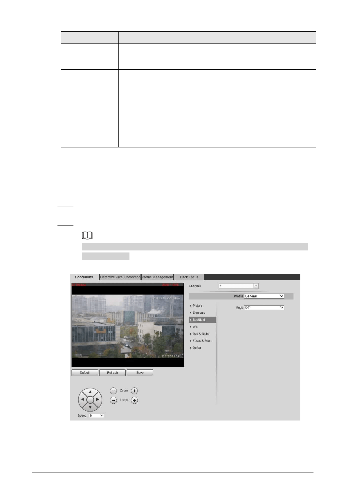
105
Parameter Description
Shutter
When selecting
Manual
or
Shutter Priority
in
Mode
, you can set Shutter.
Set the effective exposure time. The smaller the value, the shorter the
exposure.
Basic NR
Select the
On
checkbox to enable this function. Aiming at single-frame
image, 2D NR averages the pixel points (points that are with image noise)
with other common pixel points to decrease the image noise and achieve
an acceptable and good image display effect. The higher the grade, the
better the noise suppression effect.
Advanced NR
Select the
On
checkbox to enable this function. Aiming at multiple-frame
image, 3D NR handles information between two frames to reduce the
image noise. The higher the grade, the better the noise suppression effect.
Grade You can select the grade from
Low
,
Medium
, and
High
.
Step 5 Click
Save
.
6.1.1.1.3 Configuring Backlight Parameters
You can select backlight mode from Off, BLC, WDR, and HLS.
Step 1 Select
Setting
>
Camera
>
Conditions
>
Conditions
.
Step 2 Select
1
in
Channel
.
Step 3 Click the
Backlight
tab.
Step 4 Configure backlight parameters.
There might be a few seconds of video loss when the Camera is switching to WDR mode
from other modes.
Figure 6-4 Backlight

106
Table 6-3 Backlight mode description
Backlight Mode Description
Off Disable the backlight function.
BLC
The system adjusts exposure according to ambient lighting condition
automatically to ensure the clarity of the darkest area.
WDR
The system dims bright areas and compensates dark areas to ensure the
clarity of all the area.
HLS
The system constrains bright areas and reduces halo size to dim the
overall brightness.
Step 5 Click
Save
.
6.1.1.1.4 Configuring White Balance Parameters
White balance function makes the image color display precisely as it is. When in white balance
mode, white objects would always display white color in different environments.
Step 1 Select
Setting
>
Camera
>
Conditions
>
Conditions
.
Step 2 Select
1
in
Channel
.
Step 3 Click the
WB
tab.
Step 4 Configure white balance parameters.
Figure 6-5 White balance
Table 6-4 White balance mode description
WB Mode Description
Auto
The system compensates WB according to light condition to ensure color
precision.
Outdoor
The system auto compensates WB to most outdoor environments with
natural or artificial light to ensure color precision.
Manual
Configure red and blue gain manually; the system auto compensates WB
according to color temperature.

107
WB Mode Description
Natural
The system auto compensates WB to environments without artificial light
to ensure color precision.
Street Lamp
The Camera will implement white balance to ensure precision and clarity
of the video image.
Step 5 Click
Save
.
6.1.1.1.5 Configuring Day & Night Parameters
Configure the display mode of the image. The system switches between color and black-and-white
mode according to the actual condition.
Step 1 Select
Setting
>
Camera
>
Conditions
>
Conditions
.
Step 2 Select
1
in
Channel
.
Step 3 Click the
Day & Night
tab.
Step 4 Configure day & night parameters.
Figure 6-6 Day & night
Table 6-5 Day & night mode description
Parameter Description
Type Select the type from
Electrical
and
ICR
.
Mode
You can select camera display mode from
Color
,
Auto
and
B/W
.
Day & night configuration is independent from profile management
configuration.
●
Color
: The system displays color image.
●
Auto
: The system switches between color and black-and-white display
according to the actual condition.
●
B/W
: The system displays black-and-white image.

108
Parameter Description
Sensitivity
Select
Auto
as the
Mode
. Then you can configure this parameter.
You can configure the camera sensitivity for switching between color and
black-and-white mode.
Delay
This configuration is available only when you set
Auto
in
Mode
.
You can configure the delay when the Camera switching between color and
black-and-white mode. The lower the value is, the faster the Camera
switches between color and black-and-white mode.
6.1.1.1.6 Configuring Focus & Zoom Parameters
Initializes lens to adjust zoom and focus.
Step 1 Select
Setting
>
Camera
>
Conditions
>
Conditions
.
Step 2 Select
1
in
Channel
.
Step 3 Click the
Focus & Zoom
tab.
Step 4 Configure the focus & zoom parameters.
Figure 6-7 Focus & zoom
Table 6-6 Focus & zoom parameters
Parameter Description
Digital Zoom
Select the
On
checkbox to enable it.
You can use the digital zoom to continue the zooming operation even
if the optical zoom is at the maximum value.
Zoom Speed The larger the value, the faster the zooming operation.

109
Parameter Description
Mode
The focusing mode of the Camera.
●
Auto: When image moves or object changes in the scene, the
Camera will focus automatically.
●
Semi Auto: Click or corresponding to
Focus
or
Zoom
, the
Camera will focus. Calling preset, positioning accurately or rotating
PTZ also will trigger focus.
●
Manual: You need to click or corresponding to
Focus
to
adjust the focus.
Focus Limit
When the focus length is too short, the Camera will focus on the dome
cover. Sets the shortest focus distance to avoid focusing on the dome
cover. You can also change the focus speed by changing focus length.
Sensitivity
Select from
High
,
Default
and
Low
. When you select
High
, it will be
easier for the Camera to focus.
Lens Initialization
Click
Lens Initialization
to initialize the lens. The system will clear the
zooming and focusing data that you have set.
Step 5 Click
Save
.
6.1.1.1.7 Configuring Defog Parameters
The image quality is compromised in foggy or hazy environment, and defog can be used to improve
image clarity.
Step 1 Select
Setting
>
Camera
>
Conditions
>
Conditions
.
Step 2 Select
1
in
Channel
.
Step 3 Click the
Defog
tab.
Step 4 Configure the defogging settings.
Figure 6-8 Defog

110
Table 6-7 Defogging settings description
Defogging Settings Description
Auto The system adjusts image clarity according to the actual condition.
Manual
Configure function intensity manually, and then the system adjusts
image clarity accordingly. Set the intensity higher when the image is not
clear.
Off Defog function is disabled.
Step 5 Click
Save
.
6.1.1.2 Configuring Thermal Image
Configure a specific scenario where you use the Camera, including indoor scenario, outdoor
scenario, and adaptive scenario. You can choose a scenario as needed, and configure and check the
scenario.
Step 1 Select
Setting
>
Camera
>
Conditions
>
Conditions
.
Step 2 Select
1
in
Channel
.
Step 3 Configure the profile. For details, see "6.1.1.4 Configuring Profile Management".
Step 4 Select the colorization and scenario.
The thermal image page might vary with different models.
Figure 6-9 Thermal image
Step 5 Configure lens parameters.

111
Table 6-8 Description of lens parameters
Parameter Description
Scene Type
Select the duplicate frame and set the frequently used video parameter
as the user-defined scene. Or you can select the default scene and set
the display of the thermal image.
●
Low Dynamic
: Thermal images will be displayed based on the
configuration of low dynamic scene.
●
High Dynamic
: Thermal images will be displayed based on the
configuration of high dynamic scene.
●
Auto
: Thermal images will be displayed based on the configuration
of auto scene
●
None
: Do not set the scene.
Profile
Normal
,
Day
and
Night
can be selected.

112
Parameter Description
Colorization
Add color to the thermal image and use color to indicate the
temperature.
White Glow
is the default color.
●
White glow: Lighter when the temperature is higher in gray image.
●
Black glow: Lighter when the temperature is lower in gray image.
●
Fusion: Color is concentrated on the range of purple- red-yellow.
More purple when the temperature is lower and more yellow when
the temperature is higher.
●
Rainbow: Color is concentrated on the range of blue- green-red-
yellow. Bluer when the temperature is lower and more yellow
when the temperature is higher.
●
Golden autumn: Color is concentrated on the range of red- yellow.
Redder when the temperature is lower and more yellow when the
temperature is higher.
●
Midday: Color is concentrated on the range of blue- green-red-
yellow. Bluer when the temperature is lower and more yellow
when the temperature is higher.
●
Iron oxide red: Its color range is similar to that of Midday, but its
brightness is lower than Midday.
●
Amber: It’s mainly represented as brown. Brighter when the
temperature is higher.
●
Boulder: Color is concentrated on the range of purple - red- yellow-
green- blue. More purple when the temperature is lower and bluer
when the temperature is higher.
●
The setting sun: Color is concentrated on the range of blue- red-
yellow. Bluer when the temperature is lower and more yellow
when the temperature is higher.
●
Ice and fire: In color image, high temperature objects show red and
low temperature objects show blue. Ice and fire is usually used to
give a warning.
●
Oil painting: Color is concentrated on the range of purple-blue-
green- yellow-red. More purple when the temperature is lower and
redder when the temperature is higher.
●
Pomegranate: It is mainly represented as wine red. Brighter when
the temperature is higher.
●
Green jade: It is mainly represented as aquamarine. Brighter when
the temperature is higher.
Step 6 (Optional) Configure the advanced parameters.
When the scene cannot meet the scene requirements, configure the advanced parameters
manually.

113
Table 6-9 Advanced parameter description
Classification Parameter Description
Basic Settings
Brightness
Change the overall image brightness
through linear mode. The bigger the value
is, the brighter the image will be, and the
smaller the darker.
Contrast
Changes the contrast of the image. The
higher the value is, the more the contrast
will be between bright and dark areas, and
the smaller the less. If the value is set too
big, the dark area would be too dark and
bright area easier to get overexposed. The
image might be hazy if the value is set too
small.
Sharpness
Change the sharpness of image edges. The
larger the value, the more obvious the
image edge.
Do not make the value too large to prevent
image noise.
DDE
Makes the details of the image clear. The
bigger the value is, the clearer the details
will be.
Digital Zoom
Enlarge the thermal image according to
the zoom time you have set.
Mirror
Open the mirror image and the monitor
image will reverse from left to right.
Flip
Changes the display direction of the
picture, see the options below.
●
0°: Normal display.
●
90°: The picture rotates 90° clockwise.
●
180°: The picture rotates 90°
counterclockwise.
●
270°: The picture flips upside down.
For some models, configure the resolution
to be 1080p or lower when using 90° and
180°. For details, see "6.1.2.1 Configuring
Video Streaming".

114
Classification Parameter Description
Fusion Mode
Displays the image with the gray scale
information of the visible channel, and
marks temperatures with color palettes,
which makes the image of the thermal
channel clearer.
●
Original
: Displays the image of the
thermal channel.
●
Warm Color
: Combines the data of the
visible channel and the thermal
channel, and displays the image in
warm color.
●
Cold Color
: Combines the data of the
visible channel and the thermal
channel, and displays the image in cold
color.
●
Fusion Rate
: It ranges from 0 to 100.
The larger the value, the larger the
proportion of the visible channel.
●
Dual-lens Calibration Adjustment
:
You can adjust the misaligned images
through direction keys.
●
Speed
: The moving speed of the lens
when adjusting the image.
To get a better fusion effect, keep the
distance 3 m between the Camera and the
targets.
Noise Reduction 2D NR
Compares one frame to the next and
removes any oddity that does not appear
in each frame.
The larger the value is, the fuzzier the
image will be.

115
Classification Parameter Description
3D NR
Removes the grainy fuzzy appearances of
low light images, will handle moving
objects without leaving tails behind, and in
low light, it makes an image clearer and
sharper.
●
Basic 3D NR: The module handles noise
reduction.
●
Advanced 3D NR: The back-end
program handles noise reduction.
Generally, you can select
2D NR
and
Basic
3D NR
. If the image is not clear, select
Advanced 3D NR
, and configure the
parameters.
Gain settings
Auto Gain
The larger the gain value, the more
unstable the image.
Gain Mode
Low-temperature mode, high-temperature
mode and auto mode are contained.
FFC Settings
FFC Mode
Method of correcting the shutter.
●
Auto: According to the switch period
that you have configured, the shutter
will be corrected regularly.
●
Manual: Correct the shutter by
yourself.
FFC Period
You can configure this parameter only
when
FFC Mode
is set to be
Auto
.
Adjust time gap of correcting the shutter
automatically.
Do FFC
Click
Do FFC
to trigger the shutter
correcting for this time.
Step 7 Click
Save
.
6.1.1.3 Configuring Defective Pixel Correction
When there are a few defective pixels to be corrected, you can correct them manually.
Step 1 Select
Setting
>
Camera
>
Conditions
>
Defective Pixel Correction
.
Step 2 Select the
Enable
checkbox.
Step 3 Select the calibration mode. Generally, you can select
Picture
, and for the image with
defective pixels that appears occasionally, select
Video
.
Step 4 Click to add the point of Defective Pixel Correction.

116
Figure 6-10 Thermal image
Step 5 Click a defective pixel on the image, and is displayed near the defective pixel.
Step 6 Roll the mouse wheel to zoom in the image.
Step 7 Click the defective pixel again, and overlaps the defective pixel.
Step 8 Click
Calibration Confirmed
.
Step 9 Click
Setting
.
Step 10 Click
Save
.
To correct multiple defective pixels at the same time, calibrate one defective pixel, repeat
Step1–Step8, and then do Step9–Step10.
6.1.1.4 Configuring Profile Management
When configuring the profile management, you can select from
Normal
,
Full Time
and
Schedule
.
Step 1 Select
Setting
>
Camera
>
Conditions
>
Profile Management
.
Step 2 Select the channel.
●
Select
1
in
Channel
to configure the profile management for the visible channel.
●
Select
2
in
Channel
to configure the profile management for the thermal channel.
Step 3 Configure profile management.
●
When
Profile Management
is set as
Normal
, the surveillance system works under
normal configuration.
Figure 6-11 Common setting
●
When
Profile Management
is set as
Full Time
, you can select
Day
or
Night
as
Always
Enable
, and the surveillance system works under
Always Enable
.

117
Figure 6-12 Full time setting
●
When
Profile Management
is set as
Schedule
, you can drag the slide block to set
certain time as Day or Night. For example, set 8:00–5:00 PM as day, and 0:00–8:00
and18:00–24:00 as night. System works under corresponding configuration in different
time.
Figure 6-13 Switching based on time
Step 4 Click
Save
.
6.1.2 Configuring Video Parameters
6.1.2.1 Configuring Video Streaming
Configure video stream parameters, such as compression, resolution, frame rate, bit rate type, bit
rate, I frame interval, SVC, and watermark.
Step 1 Select
Setting
>
Camera
>
Video
>
Video
.
Step 2 Select the channel.
●
Select
1
in
Channel
to configure the video parameters for the visible channel.
●
Select
2
in
Channel
to configure the video parameters for the thermal channel.
Step 3 Configure video streaming parameter.

118
Figure 6-14 Video
Table 6-10 Parameter description
Parameter Description
Enable
Select the checkbox to enable sub stream (enabled by default).
Enabling sub stream 1 and sub stream 2 at the same time are
supported.
Encode Mode
Encode mode of video.
●
H.264: Main profile encode mode.
●
H.264H: High profile encode mode.
●
H.264B: Baseline profile encode mode.
●
MJPEG: Under this mode, the higher streaming value is
required to ensure the clarity of images. And we recommend
you use the maximum streaming value that we have offered.
Resolution
The resolution of the video. The max resolution of different
Cameras might be different.
Frame Rate (FPS)
The number of frame in one second of video The higher the FPS is,
the clearer and smoother the video will be.
Bit Rate Type
You can select bit rate type:
●
Fixed: the bit rate changes little and keeps close to the
configured bit rate value.
●
Changeable: the bit rate changes as monitoring scene changes.
Bit rate type can only be set as
Fixed
when
Encode Mode
is set as
MJPEG
.
Quality
This parameter can be configured only when the bit rate type is set
as
VBR
.
Reference Bit Rate
According to resolution and frame rate that you have configured,
we have offered you a reference bit rate value, which is also the
best value that you can adopt.
Bit Rate
This parameter can be configured only when the bit rate type is set
as
Fixed
.
If you select the bit rate value according to
Reference Bit Rate
value
, the streaming changes little and keeps close to the bit rate
value you have selected.
Select
Customized
and you can configure bit rate value manually.

119
Parameter Description
Maximum Bit Rate
This parameter can be configured only when bit rate type is set as
VBR
.
You can select the max value of the bit rate according to the
reference bit rate value, and the bit rate changes with monitoring
scenes, but the max bit rate keeps close to the value you set.
I Frame Interval
The number of P frame between two I frames, and the I Frame
Interval range changes as FPS.
It is recommended to set I Frame Interval twice as big as FPS.
SVC
Scaled video coding, able to encode a high quality video bit stream
that contains one or more subset bit streams. The default value is 1,
which means no layered coding.
Watermark Settings
Select the checkbox to enable watermark.
Then you can check if the video has been tampered by verifying the
watermark.
Watermark character
The default character is Digital CCTV.
You can configure at most 128 watermark characters which are
composed of number, letter, underline and dash.
Step 4 Click
Save
.
6.1.2.2 Configuring Image Streaming
Configure parameters of image streaming which cover snapshot type/interval, image size/quality.
Step 1 Select
Setting
>
Camera
>
Video
>
Snapshot
.
x
Step 2 Select the channel.
●
Select
1
in
Channel
to configure the video parameters for the visible channel.
●
Select
2
in
Channel
to configure the video parameters for the thermal channel.
Step 3 Configure snapshot streaming.
Figure 6-15 Snapshot

120
Table 6-11 Parameter description
Parameter Description
Snapshot type
You can select
General
or
Event.
●
General
means the system takes snapshot as scheduled
●
Event
means snapshot functions when video\audio detection,
event or alarm is triggered.
Image Size The same resolution with main stream.
Quality
Snapshot quality. The bigger the value, the better the snapshot
quality.
Interval
Snapshot frequency.
Select
Customized
to manually configure snapshot frequency.
HeatMap in Jpeg
When you select channel 2, you can configure this parameter.
Select the checkbox and snapshots of thermal images will carry the
temperature-measurement information.
Step 4 Click
Save
.
6.1.2.3 Configuring Video Overlay
Configure overlay information, and it will be displayed on the
Live
page.
6.1.2.3.1 Configuring Privacy Masking
You can enable this function when you need to protect the privacy of some area on the image.
Step 1 Select
Setting
>
Camera
>
Video
>
Overlay
.
Step 2 Select the channel
●
Select
1
in
Channel
to configure the parameters for the visible channel.
●
Select
2
in
Channel
to configure the parameters for the thermal channel.
Step 3 Click the
Privacy Masking
tab.
Step 4 Select the
Enable
checkbox.
Step 5 Click
Add
. Double-click the block name to edit it, and click the color to select the block
color.
Step 6 Draw a block on the image. You can drag the corner of the block to adjust the size and
drag it to the place that you want to mask.
●
You can draw four area boxes at most.
●
Click
Remove All
to delete all the area boxes; you can also just select one box, and click
Delete
or right-click to delete it.

121
Figure 6-16 Privacy masking
Step 7 Click
Save
.
6.1.2.3.2 Configuring Channel Title
You can enable this function if you need to display Channel title in the video image.
Step 1 Select
Setting
>
Camera
>
Video
>
Overlay
.
Step 2 Select the channel
●
Select
1
in
Channel
to configure the parameters for the visible channel.
●
Select
2
in
Channel
to configure the parameters for the thermal channel.
Step 3 Click
Channel Title
.
Figure 6-17 Channel title
Step 4 Select the
Enable
checkbox, and then enter channel title. The title displays in the video
image.
You can drag the
Channel Title
box on the video image with your mouse to adjust the
location of the box.
Step 5 Click
Save
.

122
6.1.2.3.3 Configuring Time Title
You can enable this function if you need to display time on the video image.
Step 1 Select
Setting
>
Camera
>
Video
>
Overlay
.
Step 2 Select the channel
●
Select
1
in
Channel
to configure the parameters for the visible channel.
●
Select
2
in
Channel
to configure the parameters for the thermal channel.
Step 3 Click
Time Title
.
Figure 6-18 Time title
Step 4 Select the
Enable
checkbox, and the time is displayed on the video image.
Step 5 Click
Week Display
, and then the week information is displayed on the video image.
You can drag the
Time Title
box on the video image with your mouse to adjust the box’s
location.
Step 6 Click
Save
.
6.1.2.3.4 Configuring OSD Info
You can enable this function if you want to display preset title, temperature, PTZ life warning,
coordinates, zoom, north direction, pattern, RS-485, battery information, and other information on
the video image.
Step 1 Select
Setting
>
Camera
>
Video
>
OSD Info
.
Step 2 Select the channel
●
Select
1
in
Channel
to configure the parameters for the visible channel.
●
Select
2
in
Channel
to configure the parameters for the thermal channel.
Step 3 Click
OSD Info
.

123
Figure 6-19 OSD Info
Step 4 Configure OSD information.
Parameter Description
Preset
Select the
Enable
checkbox, and the preset name is displayed on the
image when the Camera turns to the preset, and it will disappear 3 s later.
PTZ Life Warning
When the PTZ lifespan is close to the threshold, a warning will be
displayed on the video image. This OSD info is enabled by default.
Coordinates
Select the
Enable
checkbox, and the PTZ coordinates information is
displayed on the image.
Zoom
Select the
Enable
checkbox, and the zoom information is displayed on
the image. For example, means 12× zoom rate.
North
Select the
Enable
checkbox, and the north direction is displayed on the
image. For details, see "5.7.3 Configuring North".
Pattern
Select the
Enable
checkbox, and the pattern information is displayed on
the image.
Text Overlay
Select the
Enable
checkbox, and then enter text. The text is displayed on
the image.
Input Text
Text Align Set the alignment mode of the displayed information on the image.
Step 5 Move the OSD box to the position that you want on the image.
Step 6 Click
Save
.
6.1.2.3.5 Configuring Font
You can adjust size and color of the font on the video images based on your own needs.
Step 1 Select
Setting
>
Camera
>
Video
>
Overlay
.
Step 2 Select the channel
●
Select
1
in
Channel
to configure the parameters for the visible channel.
●
Select
2
in
Channel
to configure the parameters for the thermal channel.
Step 3 Click the
Font
tab.

124
Figure 6-20 Font setting
Step 4 Select color and size of the font as needed.
Step 5 Click
Save
.
6.1.2.3.6 Configuring Picture Overlay
You can enable this function if you need to display picture information on the video image.
Text overlay and picture overlay cannot work at the same time.
Step 1 Select
Setting
>
Camera
>
Video
>
Overlay
.
Step 2 Select the channel
●
Select
1
in
Channel
to configure the parameters for the visible channel.
●
Select
2
in
Channel
to configure the parameters for the thermal channel.
Step 3 Click the
Picture Overlay
tab.
Figure 6-21 Picture overlay
Step 4 Select the
Enable
checkbox.
You will be informed that OSD information is to be closed. Click
Save
.
Step 5 Click
Upload Picture
, and select a picture. The picture is displayed in video images.

125
You can drag the
Picture Overlay
box in the video image with your mouse to adjust the
box’s location.
Step 6 Click
Save
.
6.1.2.3.7 Configuring Voltage Information
After enabling this function, the voltage information will be displayed on the image when the
camera voltage is abnormal.
Step 1 Select
Setting
>
Camera
>
Video
>
Overlay
.
Step 2 Select the channel
●
Select
1
in
Channel
to configure the parameters for the visible channel.
●
Select
2
in
Channel
to configure the parameters for the thermal channel.
Step 3 Click the
Voltage Info
tab.
Step 4 Select
On
.
The picture overlay function will be disabled after the voltage information function is
enabled.
Figure 6-22 Voltage information
Step 5 Click
Save
.
When the camera voltage is abnormal, the voltage information will be displayed om the
image.
For example, for a Camera requires 12V voltage, when the voltage exceeds± 15%, the
abnormal voltage information will be displayed on the image, prompting the customer to
check the voltage.
6.1.2.4 Configuring ROI
Select ROI in the image, and then the selected image would display with configured quality.
Step 1 Select
Setting
>
Camera
>
Video
>
ROI
.
Step 2 Select the channel
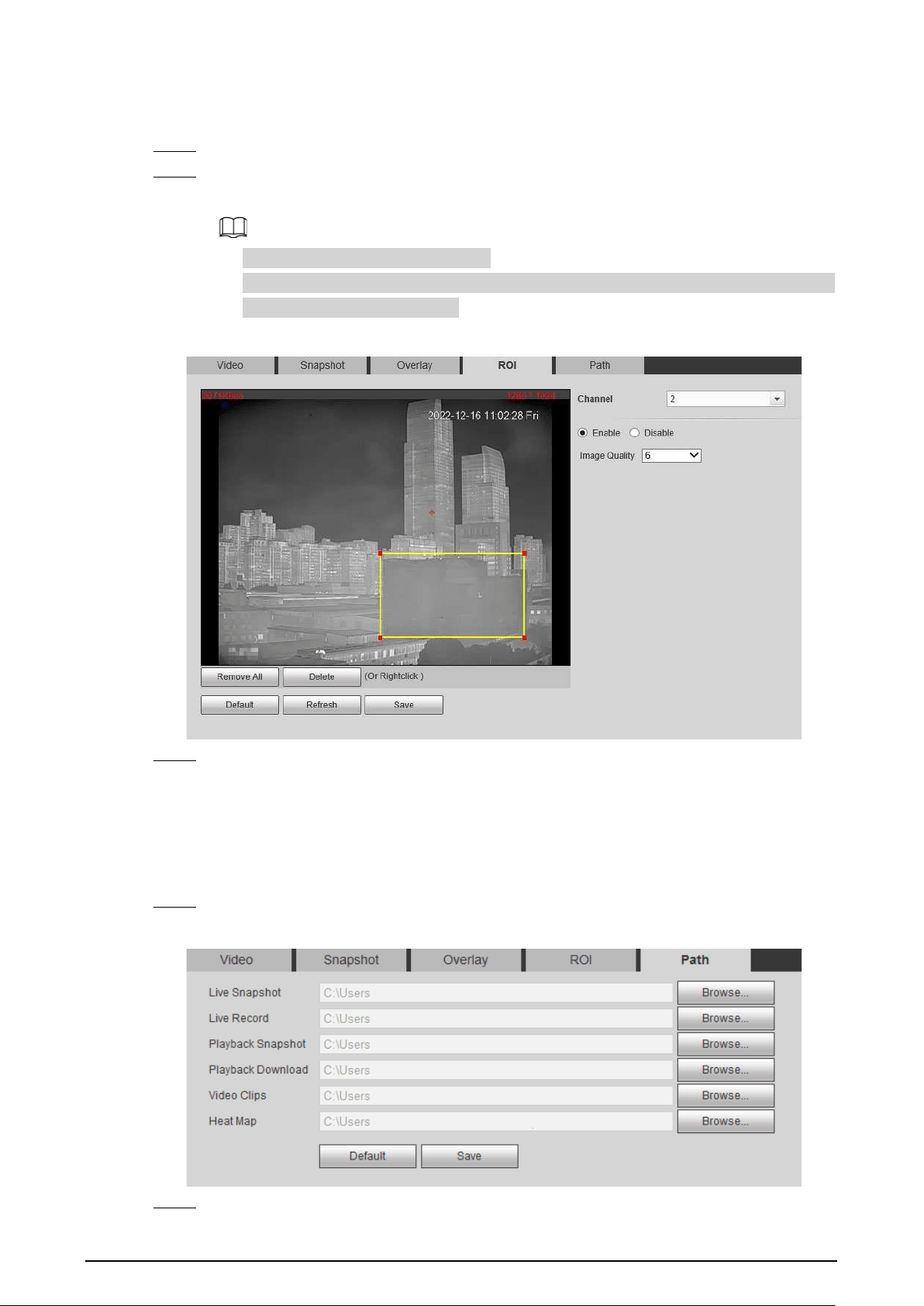
126
●
Select
1
in
Channel
to configure the parameters for the visible channel.
●
Select
2
in
Channel
to configure the parameters for the thermal channel.
Step 3 Select the
Enable
checkbox.
Step 4 Hold the left mouse button to draw a ROI area on video images. You can also configure the
display quality OF ROI.
●
You can draw at most four ROI areas.
●
Click
Remove All
to delete all the area boxes; you can also just select one box, and click
Delete
or right-click to delete it.
Figure 6-23 ROI page
Step 5 Click
Save
.
6.1.2.5 Configuring Storage Path
Configure storage paths covering
Live Snapshot
,
Live Record
,
Playback Snapshot
,
Playback
Download
,
Video Clips
, and
Heat Map
.
Step 1 Select
Setting
>
Camera
>
Video
>
Path
.
Figure 6-24 Storage path
Step 2 Click
Browse
, and configure storage paths of live snapshot, live record, playback snapshot,
127
playback download, video clips, and heat map.
Table 6-12 Storage path description
Path Description
Live Snapshot
Live snapshot refers to the snapshot of live page.
C:\Users\admin\WebDownload\LiveSnapshot is the default path.
Live Record
Live record refers to the recorded video of live page.
C:\Users\admin\WebDownload\LiveSnapshot is the default path.
Playback Snapshot
Playback snapshot refers to the snapshot of playback page.
C:\Users\admin\WebDownload\LiveSnapshot is the default path.
Playback Download
Playback download refers to the downloaded video of playback
page.
C:\Users\admin\WebDownload\LiveSnapshot is the default path.
Video Clips
Video clips refer to the clipped video of playback page.
C:\Users\admin\WebDownload\LiveSnapshot is the default path.
Heat Map
Heat map comes from the location
Setting
>
Temperature
.
C:\Users\admin\WebDownload\LiveSnapshot is the default path.
Administrator in the default path is the user account.
Step 3 Click
Save
.
6.1.3 Configuring Audio Parameters
Configure audio parameters covering
Encode Mode
,
Sampling Frequency
,
Audio in Type
, and
Noise Filter
.
Functions of different cameras might vary.
Step 1 Select
Setting
>
Camera
>
Audio
.

128
Figure 6-25 Audio
Step 2 Configure Audio parameters.
Table 6-13 Parameters
Parameters Description
Enable
Audio can be enabled only when video is enabled.
Enable
Main Stream
or
Sub Stream
, and the network stream is composed
of both audio and video streams. If you do not select
Main Stream
or
Sub
Stream
, then only video images are transmitted.
Encode Mode
You can select audio encode mode. G.711A, G.711Mu, and AAC are
included.
The configured audio encode mode applies to audio and intercom.
Sampling
Frequency
Audio’s sampling frequency. 8K and 16K are included.
Audioin Type
Two audio types are selectable.
●
LineIn
: External audio input source is required.
●
Mic
: External audio input source is not required.
Noise Filter Enable this function, and the system auto filters ambient Noise.

129
Parameters Description
Microphone
Volume
Adjusts microphone volume.
This function is available on select models.
Speaker Volume
Adjusts speaker volume.
This function is available on select models.
Step 3 Click
Save
.
6.2 Configuring Network
6.2.1 Configuring TCP/IP
You can configure IP address, DNS (Domain Name System) server and so more according to network
planning.
Prerequisites
You have connected the Camera to network.
Procedure
Step 1 Select
Setting
>
Network
>
TCP/IP
.
Figure 6-26 TCP/IP page
Step 2 Configure TCP/IP parameters.

130
Table 6-14 TCP/IP parameters
Parameter Description
Host Name Enter the host name, 15 characters at most.
Ethernet Card
Wire (Default)
is set by default.
Mode
●
Static: You need to manually configure
IP Address
,
Subnet Mask
and
Default Gateway
.
●
DHCP: Obtains IP address automatically. With DHCP enabled,
IP
Address
,
Subnet Mask
and
Default Gateway
cannot be
configured. You can check the current IP address whether the
DHCP takes effect or not.
MAC Address Host’s MAC address, cannot be modified.
IP Version Select IPv4 or IPv6.
IP Address Enter the IP address and subnet mask according to your own needs.
All the IPv6 addresses will be validated, so ensure IP address and
subnet mask are in the same network segment, which means the front
parts of the IP address and the default gateway are the same one.
Subnet Mask
Default Gateway
Configure it as needed, the default gateway must be in the same
network segment with the IP address.
Preferred DNS IP address of the preferred DNS.
Alternate DNS IP address of the alternate DNS.

131
Parameter Description
Enable ARP/Ping to set
IP address service.
Select the checkbox, get the camera MAC address, and then you can
modify and configure the camera IP address with ARP/ping command.
It is enabled by default. During restarting, you will have no more than
two minutes to configure the camera IP address with a ping packet
which has certain length. The server will be turned off in 2 minutes, or
it will be turned off immediately after IP address configuration. If it is
not enabled, the IP address cannot be configured with ping packet.
A demonstration of configuring IP address with ARP/Ping.
To obtain a free IP address, you need to ensure that the Camera and
your PC are in the same LAN.
Get MAC address from the Camera label.
Open command editor on your PC and enter the following command.
Restart through power or network.
Check your PC command line. If there is information such as "Reply
from 192.168.0.125…", you have done configuration successfully. Turn
it off then.
Enter http://(IP address) in the browser address bar to log in.
Step 3 Click
Save
.
6.2.2 Configuring Port
Configure the port numbers and the maximum number of users (includes web, platform client, and
mobile phone client) that can connect to the device simultaneously.
Step 1 Select
Setting
>
Network
>
Port
.

132
Figure 6-27 Port
Step 2 Configure parameters.
●
0–1024, 1900, 3800, 5000, 5050, 9999, 37776, 37780–37880, 39999, 42323 are occupied
for specific uses.
●
Do not use the same value of any other port during port configuration.
Table 6-15 Port parameter description
Parameter Description
Max Connection
The maximum number of users (web client, platform client or mobile
phone client) that can connect to the Camera simultaneously, the
value is 10 by default.
TCP Port Port of transmission control protocol. The value is 37777 by default.
UDP Port User datagram protocol port, the value is 37778 by default.
HTTP Port
HTTP communication port. The default value is 80. If you have
modified the default value, when logging in through a browser, you
need to add the latest port number to the end of IP address.

133
Parameter Description
RTSP Port
●
554 is the default port number. If you play live view through
Apple’s QuickTime or VLC, the following format is available. This
function is also available for Blackberry.
●
When the URL format requiring RTSP, you need to specify
channel number and bit stream type in the URL, and also user
name and password if needed.
●
When playing live view with Blackberry smart phone, you need
to turn off the audio, and then set the code mode to H.264B and
resolution to CIF.
●
Username: admin, for example.
●
password
●
IP: your Camera IP.
●
Port: leave it if the value is 554 by default.
●
Channel 1: Channel number, starts from 1. For example, if you
are using channel 2, then the channel=2.
●
Subtype refers to Bit stream type; 0 means main stream
(Subtype=0) and 1 means sub stream (Subtype=1).
rtsp://ip:port/cam/realmonitor?channel=1&subtype=0
HTTPS Port
Real Time Messaging Protocol. The port that RTMP provides service.
It is 1935 by default.
HTTPS Port HTTPS communication port. It is 443 by default.
5000 Port The service port for Windows XP. It is
Off
by default.
Step 3 Click
Save
.
The configuration of
Max Connection
takes effect immediately, and others will take effect
after restart the Camera.
6.2.3 Configuring PPPoE
Point-to-Point Protocol over Ethernet, is one of the protocols that device uses to connect to the
internet. Get the PPPoE username and password from the internet service provider, and then set up
network connection through PPPoE, the camera will acquire a WAN dynamic IP address.
●
The Camera has connected to the network.
●
You have gotten the account and password from Internet Service Provider.
Step 1 Select
Setting
>
Network
>
PPPoE
.
Step 2 Select the
Enable
checkbox, and then enter the user name and password.
●
Disable UPnP while using PPPoE to avoid possible influence.
●
After making PPPoE connection, the camera IP address cannot be modified through
web page.

134
Figure 6-28 PPPoE
Step 3 Click
Save
.
The successful prompt displays, and then the real-time WAN IP address is displayed. You
can visit the Camera through this IP address.
6.2.4 Configuring DDNS
Properly configure DDNS, and then the domain name on the DNS server matches your IP address
and the matching relation refreshes in real time. You can always visit the Camera with the same
domain name no matter how the IP address changes.
Prerequisites
Check the DNS server types that the Camera supports.
●
Third party server might collect your device information after DDNS is enabled.
●
Register and log in to the DDNS website, and then you can view the information of all the
connected devices in your account.
Procedure
Step 1 Select
Setting
>
Network
>
DDNS
.
Step 2 Select the
Type
checkbox, and then configure the parameters as needed.
Figure 6-29 DDNS
Table 6-16 DDNS parameters
Parameter Description
Type See the name and web site of DDNS service provides below:

135
Parameter Description
Address
●
"members.dyndns.org" is the IP address of Dyndns DDNS.
●
"dynupdate.no-ip.com" is the IP address of NO-IP DDNS.
●
"members.3322.org" is the IP address of CN99 DDNS.
Domain name The domain name that you registered on the DDNS website.
User name Enter the user name and password that you got from DDNS service
provide. You need to register an account (with user name and password)
on the DDNS service provides’ website.
Password
Update period
The update cycle of the connection between your Camera and the server.
10 minutes are set by default.
Step 3 Click
Save
.
Open your browser, and type the domain name into address bar. Press Enter. If a web page
is displayed, the configuration is finished successfully.
6.2.5 Configuring SMTP
Configure
SMTP (Email)
parameter and enable email linkage. The system sends email to the defined
address when the corresponding alarm is triggered.
Step 1 Select
Setting
>
Network
>
SMTP (Email)
.
Figure 6-30 SMTP (Email)
Step 2 Configure the parameters to be configured.

136
Table 6-17 SMTP (Email) parameter description
Parameter Description
SMTP Server SMTP server address
For details, see Table 6-18.
Port
The port number of the SMTP
server.
Username The account of SMTP server.
Password The password of SMTP server.
Anonymous
Select the ckeckbox, and the sender's information is not displayed in
the email.
Sender Sender’s email address.
Encryption Type
Select from
None
,
SSL
and
TLS
.
For details, see Table 6-18.
Subject
Enter maximum 63 characters in Chinese, English, and Arabic
numerals. Click
+
to select title type, including
Device Name
,
Device
ID
, and
Event Type
, and you can set maximum 2 titles.
Attachment Select the checkbox to support attachment in the email.
Receiver
●
Receiver’s email address. Supports 3 addresses at most.
●
After entering the receiver's email address, the
Test
button is
display. Click
Test
to test whether the emails can be sent and
received successfully.
Health Mail
The system sends test mail to check if the connection is successfully
configured. Click the checkbox and configure the
Sending Interval
,
and then the system sends test mail as the set interval.
For the configuration of major mailboxes, see Table 6-18.
Table 6-18 Description of major mailbox configuration
Mailbox SMTP server Authentication Port Description
gmail
smtp.gmail.c
om
SSL 465
You need to enable SMTP service
in your mailbox.
TLS 587
Step 3 Click
Save
to save the configuration.
Step 4 Click
Test
to test whether the email works normally.
6.2.6 Configuring UPnP
UPnP (Universal Plug and Play) is a protocol that establishes mapping relation between local area
and wide area networks. This function enables you to visit local area device through wide area IP
address.
Prerequisites
●
Make sure that the UPnP service is installed in the system.
●
Log in to the router, and configure WAN IP address to set up internet connection.
●
Enable UPnP in the router.
●
Connect your Camera to the LAN port of the router.
●
Set IP address of your router as that of your Camera, or select DHCP to obtain IP address

137
automatically.
Procedure
Step 1 Select
Setting
>
Network
>
UPnP
.
Step 2 Select the
Enable
checkbox.
Step 3 Select the mode, and service name in the port mapping list.
UPnP can be classified as custom mode and default mode.
●
Select
Custom
, click , and then you can change external port as needed.
●
Select
Default
, and then the system finishes mapping with unoccupied port
automatically, and you cannot edit mapping relation.
Figure 6-31 UPnP
Step 4 Click
Save
.
Type "http://external network IP address: external port number" to access Cameras in Intranet
whose ports correspond to your router.
6.2.7 Configuring SNMP
SNMP (Simple Network Management Protocol), which can be used to enable software such as MIB
Builder and MG-SOFT MIB Browser to connect to the Camera and manage and monitor the Camera.
Prerequisites
●
Install SNMP monitoring and managing tools such as MIB Builder and MG-SOFT MIB Browser.
●
You can contact technical support for the MIB file that matches the current version.
Procedure
Step 1 Select
Setting
>
Network
>
SNMP
.
Figure 6-32 SNMP (1)

138
Figure 6-33 SNMP (2)
Step 2 Select SNMP version to enable SNMP.
●
Select
V1
, and the system can only process information of V1 version.
●
Select
V2
, and the system can only process information of V2 version.
●
Select
V3
, and then
V1
and
V2
become unavailable. You can configure username,
password and authentication type. It requires corresponding username, password and
authentication type to visit your device from the server.
Using
V1
and
V2
might cause data leakage, and
V3
is recommended.
Step 3 In
Trap Address
, enter the IP address of the PC that has MIB Builder and MG-SOFT MIB
Browser installed, and leave other parameters to the default.
Table 6-19 SNMP parameter description
Parameter Description
SNMP Port The listening port of the software agent in the device.
Read Community, Write
Community
The read and write community string that the software agent
supports.
You can enter number, letter, underline and dash to form the
name.
Trap Address
The target address of the Trap information sent by the software
agent in the device.

139
Parameter Description
Trap Port
The target port of the Trap information sent by the software agent
in the device.
Keep Alive
Select the checkbox, and then set the period. During the
configured period, the system checks whether the camera is
online.
Read-only Username
Set the read-only username accessing device, and it is
public
by
default.
You can enter number, letter, and underline to form the name.
Read&Write Username
Set the read/write username access device, and it is
private
by
default.
You can enter number, letter, and underline to form the name.
Authentication Type
You can select from
MD5
and
SHA
. It is
MD5
by default.
Authentication Password It should be no less than 8 digits.
Encryption Type It is CBC-DES by default.
Encryption Password It should be no less than 8 digits.
Step 4 Click
Save
.
Result
View device configuration through MIB Builder or MG-SOFT MIB Browser.
1. Run MIB Builder and MG-SOFT MIB Browser.
2. Compile the two MIB files with MIB Builder.
3. Load the generated modules with MG-SOFT MIB Browser.
4. Enter the IP address of the device that you need to manage in the MG-SOFT MIB Browser, and
then select version to search.
5. Unfold all the tree lists displayed in the MG-SOFT MIB Browser, and then you can view the
configuration information, video channel amount, audio channel amount, and software version.
Use PC with Windows and disable SNMP Trap service. The MG-SOFT MIB Browser will display prompt
when alarm is triggered.
6.2.8 Configuring Bonjour
Enable this function, and the OS and clients that support Bonjour would find the Camera
automatically. You can have quick visit to the Camera with Safari browser.
Bonjour is enabled by default.
Step 1 Select
Setting
>
Network
>
Bonjour
.
Step 2 Select the
Enable
checkbox, and then configure the server name.

140
Figure 6-34 Bonjour
Step 3 Click
Save
.
Result
In the OS and clients that support Bonjour, follow the steps below to visit the network camera with
Safari browser.
1. Click
Show All Bookmarks
in Safari.
2. Enable
Bonjour
. The OS or client automatically detects the network cameras with Bonjour
enabled in the LAN.
3. Click the camera to visit the corresponding web page.
6.2.9 Configuring Multicast
When multiple users are viewing the device video image simultaneously through network, it might
fail due to limited bandwidth. You can solve this problem by setting up a multicast IP (224.0.1.0–
238.255.255.255) for the Camera and adopt the multicast protocol.
Procedure
Step 1 Select
Setting
>
Network
>
Multicast
.
Figure 6-35 Multicast
Step 2 Select the channel
●
Select
1
in
Channel
to configure the parameters for the visible channel.
●
Select
2
in
Channel
to configure the parameters for the thermal channel.
Step 3 Select
Enable
, and then enter IP address and port number.
Table 6-20 Multicast
Parameter Description
Multicast Address
The multicast IP address of
Main Stream
/
Sub Stream
is 224.1.2.4 by
default, and the range is 224.0.0.0–239.255.255.255.
Port
The multicast port of corresponding stream:
Main Stream
: 40000;
Sub
Stream1
: 40016;
Sub Stream2
: 40032, and all the range is 1025–
65500.
Step 4 Click
Save
, and the login page is displayed. The configuration finishes.

141
Result
On the
Live
page, select
RTSP
in
Multicast
, and then you can view the video image with multicast
protocol.
6.2.10 Configuring Auto Registration
After you enable this function, when the Camera is connected into Internet, it will report the current
location to the specified server which acts as the transit to make it easier for the client software to
access the Camera.
Step 1 Select
Setting
>
Network
>
Auto Register
.
Step 2 Select the
Enable
checkbox.
Step 3 Set auto registration parameters.
Figure 6-36 Auto registration
Table 6-21 Auto registration parameter description
Parameter Description
IP Address
IP address or domain name to which the camera transmits its
location.
Port The port for auto registration.
Sub-Camera ID Your Camera ID given by the server.
Step 4 Click
Save
.
6.2.11 Configuring 802.1X
802.1X can control the Camera’s access to LAN.
Step 1 Select
Setting
>
Network
>
802.1x
.
Step 2 Select the
Enable
checkbox.
Step 3 Set 802.1x parameters.

142
Figure 6-37 802.1x
Table 6-22 Parameters of 802.1x
Parameter Description
Authentication PEAP (protected EAP protocol).
Username The username that was authenticated on the server.
Password Password of your username.
Step 4 Click
Save
.
6.2.12 Configuring QoS
You can solve problems such as network delay and congestion with this function. It helps to assure
bandwidth, reduce transmission delay, packet loss rate, and delay jitter to improve experience.
0–63 means 64 degrees of priority; 0 for the lowest and 63 the highest.
Step 1 Select
Setting
>
Network
>
QoS
.
Step 2 Set QoS parameters.
Figure 6-38 QoS
Table 6-23 QoS parameter description
Parameters Description
Real-time Monitor
Configure the priority of the data packets that used for network
surveillance. 0 for the lowest and 63 the highest.
Command
Configure the priority of the data packets that used for configure
or checking.
Step 3 Click
Save
.

143
6.2.13 Platform Access
6.2.13.1 P2P
P2P (peer-to-peer) technology enables users to manage devices easily without requiring DDNS, port
mapping or transit server.
Scan the QR code with your smart phone, and then you can add and manage more devices on the
mobile phone client.
Step 1 Select
Setting
>
Network
>
Access Platform
>
P2P
.
●
When P2P is enabled, remote management on device is supported.
●
When P2P is enabled and the device accesses to the network, the status shows online.
The information of the IP address, MAC address, device name, and device SN will be
collected. The collected information is for remote access only. You can cancel the
Enable
selection to reject the collection.
Figure 6-39 P2P
Step 2 Log in to mobile phone client and tap
Device management
.
Step 3 Tap
+
at the upper-right corner.
Step 4 Scan the QR code on the
P2P
page.
Step 5 Follow the instructions to finish the settings.
6.2.13.2 ONVIF
The ONVIF verification is enabled by default, which allows the network video products (including
video recording device and other recording devices) from other manufacturers to connect to your
device.

144
ONVIF is enabled by default.
Step 1 Select
Setting
>
Network
>
Access Platform
>
ONVIF
.
Step 2 Select
On
.
Figure 6-40 ONVIF
Step 3 Click
Save
.
6.2.13.3 RTMP
Through RTMP, you can access the third-party platform (such as Ali and YouTube) to realize video
live view.
●
RTMP can be configured by admin only.
●
RTMP supports the H.264, H.264 B and H.264H video formats, and the AAC audio format only.
Step 1 Select
Setting
>
Network
>
Access Platform
>
RTMP
.
Step 2 Select the
Enable
checkbox.
Make sure that the IP address is trustable when enabling RTMP.
Step 3 Configure RTMP parameters.
Figure 6-41 ONVIF

145
Table 6-24 Description of RTMP parameters
Parameter Description
Stream Type
The stream for live view. Make sure that the video format is the H.264,
H.264 B and H.264H, and the audio format is AAC.
Address Type
Includes
Non-custom
and
Custom
.
●
Non-custom
: Enter the server IP and domain name.
●
Custom
: Enter the path allocated by the server.
IP Address
When selecting
Non-custom
, you need to enter server IP address and
port.
●
IP address
: Support IPv4 or domain name.
●
Port
: We recommend that you use the default one.
Port
Custom Address
When selecting
Custom
, you need to enter the path allocated by the
server.
Step 4 Click
Save
.
6.3 Storage
The system can link record channel when an alarm event occurs. After alarm, the system stops
recording after an extended time period according to the
Record Delay
setting.
To use the record linkage function, set record plan for motion detection alarm and enable auto
recording in record control.
6.3.1 Configuring Schedule
6.3.1.1 Configuring Record Plan
After the corresponding alarm type (
Normal
,
Motion
, or
Alarm
) is enabled, the record channel links
recording.
Step 1 Select
Setting
>
Storage
>
Schedule
>
Record
.
Step 2 Select the channel
●
Select
1
in
Channel
to configure the parameters for the visible channel.
●
Select
2
in
Channel
to configure the parameters for the thermal channel.
Step 3 Set record plan.
Green represents normal record plan (such as timing recording); yellow represents motion
record plan (such as recording triggered by intelligent events); red represents alarm record
plan (such as recording triggered by alarm-in).
●
Method one: Select a record type, such as
Normal
, and directly press and drag the left
mouse button to set the time period for normal record on the timeline.

146
Figure 6-42 Record
●
Method two: Enter an actual time period.
1. Click
Setting
next to a day.
Figure 6-43 Setting (record time period)
2. Select a day, and the alarm type next to a period, and then set the period.
◇
Select
All
or checkboxes of some days to set the time period of multiple days at
one time.
◇
You can set 6 time periods per day.
Step 4 Click
Save
.
6.3.1.2 Configuring Snapshot Plan
According to the configured snapshot plan, the system enables or disables snapshot at
corresponding time.
Step 1 Select
Setting
>
Storage
>
Schedule
>
Snapshot
.
Step 2 Select the channel
●
Select
1
in
Channel
to configure the parameters for the visible channel.
●
Select
2
in
Channel
to configure the parameters for the thermal channel.
Step 3 Select snapshot type and set time period.

147
Green represents normal snapshot plan (such as timing snapshot); yellow represents
motion snapshot plan (such as snapshot triggered by intelligent events); red represents
alarm snapshot plan (such as snapshot triggered by alarm-in).
●
Method one: Select snapshot type, such as
Normal
, and directly press and drag the left
mouse button to set time period for normal snapshot on the timeline.
Figure 6-44 Snapshot
●
Method two: Enter an actual time period.
1. Click
Setting
next to a day.
Figure 6-45 Setting (snapshot time period)
2. Select a day, and the alarm type next to a period. Then set the period.
◇
Select
All
or checkboxes of some days to set the time period of multiple days at
one time.
◇
You can set 6 time periods per day.
3. You can set 6 time periods per day.
Step 4 Click
Save
.

148
6.3.1.3 Configuring Holiday Schedule
Select a day as the holiday and video recording and snapshots will be enabled on the holiday.
●
To use holiday recording function, you need to configure holiday recording schedule. For details,
see "6.3.1.1 Configuring Record Plan".
●
To use holiday snapshot function, you need to configure holiday record and snapshot schedule.
For details, see "6.3.1.2 Configuring Snapshot Plan".
Step 1 Select
Setting
>
Storage
>
Schedule
>
Holiday Schedule
.
Step 2 Select from record and snapshot.
Step 3 Select days that you need, and then set them as the holiday.
Those days with yellow color indicates that they were set as holidays.
Figure 6-46 Holiday schedule
Step 4 Click
Save
.
6.3.2 Configuring Storage Method
6.3.2.1 Configuring Storage Path
You can set the storage methods of video recording and snapshot according to event types. You can
save them in SD card, FTP or NAS.
Local storage is available only on models that support SD card.
Step 1 Select
Setting
>
Storage
>
Destination
>
Path
.

149
Figure 6-47 Path
Step 2 Select different storage paths for the recorded videos and snapshots which belong to
different event types.
Table 6-25 Path parameters
Parameter Description
Event type
Select from
Scheduled
,
Event
and
Alarm
.
Local Save in the internal SD card.
FTP Save in the FTP server.
NAS Save in the NAS (network attached storage).
Step 3 Click
Save
.
6.3.2.2 Configuring Local Storage
Displays the information of the local SD card. You can set it as read only or read & write; you can also
hot swap and format SD card.
Select
Setting
>
Storage
>
Destination
>
Local
.
●
Click
Read Only
, and then the SD card is set to read only.
●
Click
Read & Write
, and then the SD card is set to read & write.
●
Click
Hot Swap
, and then you can pull out the SD card.
●
Click
Refresh
, and then you can format the SD card.
●
Click
Format
, and you can format the SD card.
Figure 6-48 Local storage
6.3.2.3 Configuring FTP Server
FTP can be enabled only when it was selected as a destination path. When the network does not
work, you can save all the files to the internal SD card for emergency.
Step 1 Select
Setting
>
Storage
>
Destination
>
FTP
.
Step 2 Select the
Enable
checkbox, and then select the service type.
Select
FTP
or
SFPT
from the drop-down list.
SFTP
is recommended to enhance network
security.
Step 3 Configure FTP parameters.

150
Figure 6-49 FTP settings
Table 6-26 FTP parameter description
Parameter Description
Server Address The IP address of the SFTP or FTP server.
Port The port of the SFTP or FTP server.
User name The username to log in to the server.
Password The password to log in to the server.
Remote Directory The destination path in to the server.
Emergency (Local)
Select the
Emergency (Local)
checkbox, and when the FTP
server does not work, all the files are saved to the internal SD
card.
Step 4 Click
Save
.
Click
Test
to check whether the server has been properly connected.
6.3.2.4 Configuring NAS Server
This function can be enabled only when NAS has been selected as destination path. Click the
NAS
tab and you can save files in NAS server.
Step 1 Select
Setting
>
Storage
>
Destination
>
NAS
.
Figure 6-50 NAS settings
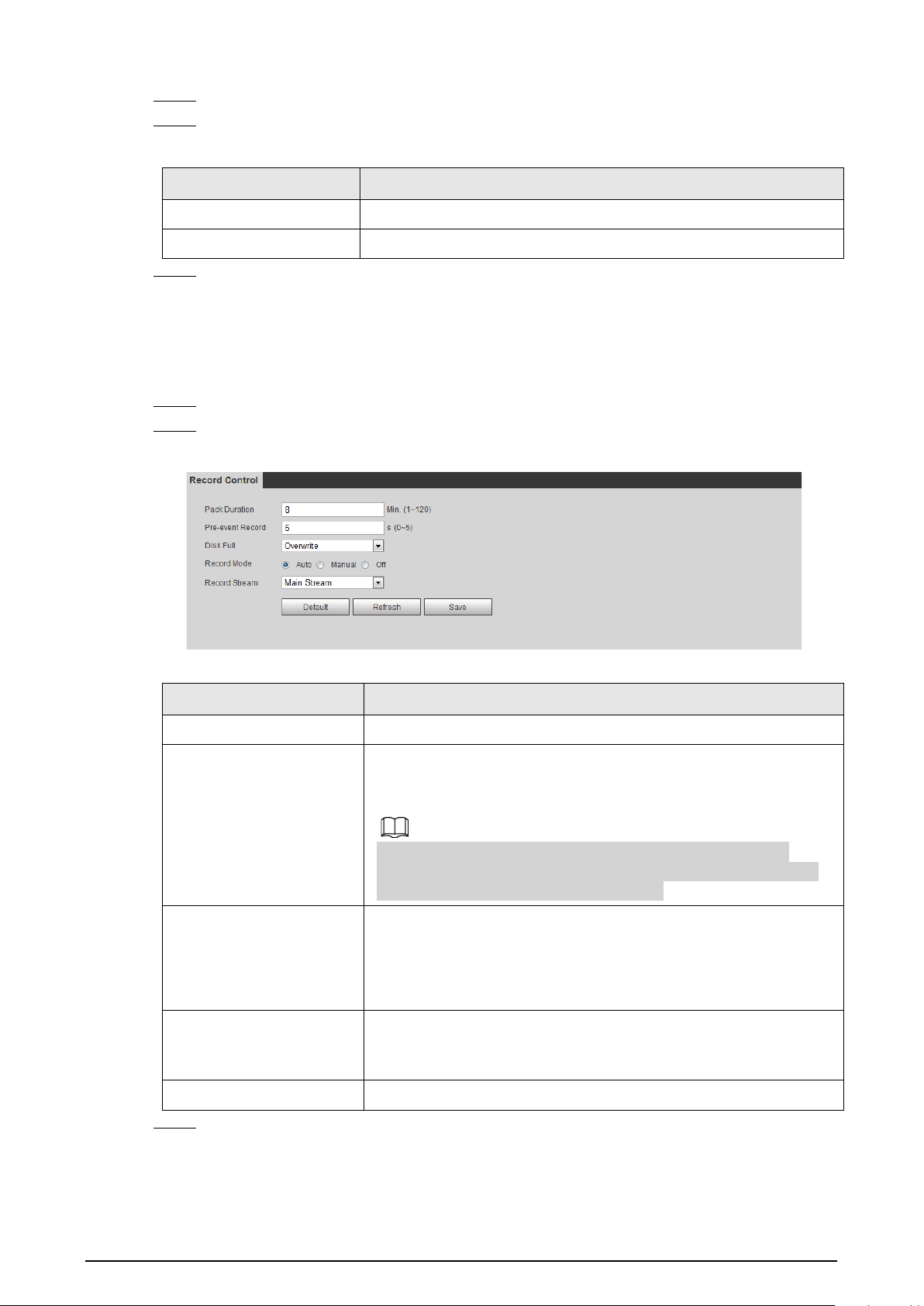
151
Step 2 Select the
Enable
checkbox.
Step 3 Configure NAS parameters.
Table 6-27 NAS parameters
Parameter Description
Server Address The IP address of the NAS server.
Remote Directory The destination path in the NAS server.
Step 4 Click
Save
.
6.3.3 Setting Record Control
Set parameters such as pack duration, pre-event record, disk full, record mode, and record stream.
Step 1 Select
Setting
>
Storage
>
Record Control
.
Step 2 Set parameters.
Figure 6-51 Record control
Table 6-28 Description of record control parameters
Parameter Description
Pack Duration The time for packing each video file.
Pre-event Record
The time to record the video in advance of a triggered alarm event.
For example, if the pre-event record is set to be 5 s, the system
saves the recorded video of 5 s before the alarm is triggered.
When an alarm or motion detection links recording, and the
recording is not enabled, the system saves the video data within
the pre-event record time to the video file.
Disk Full
Recording strategy when the disk is full.
●
Stop
: Stop recording when the disk is full.
●
Overwrite
: Cyclically overwrite the earliest video when the disk
is full.
Record Mode
When you select
Manual
, the system starts recording; when you
select
Auto
, the system starts recording in the configured time
period of record plan.
Record Stream
Select record stream, including
Main Stream
and
Sub Stream
.
Step 3 Click
Save
.

152
6.4 Peripheral
6.4.1 Configuring Illuminator
Step 1 Select
Setting
>
Peripheral
>
Illuminator
.
Figure 6-52 Illuminator
Step 2 Configure the running mode of the illuminator.
●
Zoom Prio
: When the Camera zooms in or out the visible surveillance image, the
brightness of IR illuminator will be adjusted automatically.
●
Manual
: Adjust the brightness of the illuminator manually to realize the best image
display effect under night vision condition.
Step 3 Click
Save
.
6.4.2 Configuring Wiper
Step 1 Select
Setting
>
Peripheral
>
Wiper
.
Figure 6-53 Wiper
Step 2 Configure the running mode.
●
Timing
: You can configure the
Interval Time
and
Period
.

153
1.
Interval Time
: Interval from the point when the wiper starts to the point when the
wiper stops.
2.
Period
: The working time of the wiper.
3. Click
Save
.
●
Manual
: Turn on and off the wiper manually.
1.
Interval Time
: Interval from the point when the wiper starts to the point when the
wiper stops.
2. Click
Start
to get the wiper work in the interval time that you have just configured,
and click
Stop
to stop it; click
Once
to get the wiper work for one round.
●
Auto
: Adjust the sensitivity according to the actual situation.
Step 3 Click
Save
.
6.4.3 Configuring Fan
Step 1 Select
Setting
>
Peripheral
>
Fan
.
Figure 6-54 Fan
Step 2 Select the
Enable
checkbox.
Step 3 Configure the running mode.
●
Auto
: Click
Save
, and the fan works automatically.
●
Manual
: Select the
Enable
checkbox to manually start the fan.
Step 4 Click
Save
.
6.4.4 Configuring Heater
Step 1 Select
Setting
>
Peripheral
>
Heater
.
Figure 6-55 Heater

154
Step 2 Select the heat type as needed.
Step 3 Configure the heater parameter.
●
Auto
: Select
Start Tem
and
Stop Tem
as the temperature range for heater to start, and
click
Save
. When the sensor temperature is in the range, heater works automatically.
●
Manual
: When you think it is cold enough and you want to let the Camera work in a
warm condition, you can select
Manual
as the
Mode
. Select the
On
checkbox, and then
click
Save
.
Step 4 Click
Save
.
6.5 System Management
6.5.1 General Settings
6.5.1.1 Configuring General Information
Configure the camera name, language and video standard.
Step 1 Select
Setting
>
System
>
General
>
General
.
Step 2 Configure general parameters.
Figure 6-56 General
Table 6-29 General parameter description
Parameter Description
Name
The name of the Camera.
Each Camera has a unique name.
Language Select the system language.
Video Standard Select video standard from PAL and NTSC.
Step 3 Click
Save
.
6.5.1.2 Configuring Date & Time
You can set Date and Time format, Time zone, Current Time, DST (Daylight Saving Time) or NTP
server.

155
Step 1 Select
Setting
>
System
>
General
>
Date&Time
.
Step 2 Configure Date & Time parameters.
Figure 6-57 Date & Time
Table 6-30 Date & Time parameters
Parameter Description
Date Format Date format.
Time Format Configure the time format. You can select from 24-Hour or 12-Hour.
Time zone Configure the time zone that the Camera is at.
Current Time
Configure system time.
Click
Sync PC
, and the system time changes to the time on PC.
DST
Enable DST as needed.
Select the checkbox to enable daylight saving time. Select
DST
, and
then configure the start time and end time of DST with dates or days
of the week.
NTP
When you need the Camera to transmit its time to NTP server, you can
select the
NTP
checkbox to enable it.
Server IP address or domain name of the NTP server.
Port Port number of the FTP server.
Interval Time gap of Camera’s transmission of its current time to NTP server.
Step 3 Click
Save
.

156
6.5.1.3 Configuring Position System
Enter the position system information of the Camera in the web to remind you where the Camera
locates.
When the Camera with a platform, it will automatically send the position system information to the
management platform, and the position system information can be viewed on the platform to help
the platform operator track the Camera.
This function is supported on select models.
Step 1 Select
Setting
>
System
>
General
>
Position System
.
Figure 6-58 Position system
Step 2 Enter the longitude, latitude altitude, and installation height of the Camera.
Step 3 Click
Save
.
6.5.2 User Management
Managing users and groups are only available for administrator users.
●
The max length of the user or group name is 15 characters which can only be consisted of letters,
numbers and underlines.
●
The password is made up of characters for 8–32 digits and the password must contain two of the
three forms (number, letter, and the common characters.
'
、
"
、
;
、
:
、
&
are not included.)
Administrator users can modify all the uses’ password.
●
You can have 19 users and 8 groups at most.
●
You can manage users through single user or group, duplicate user names or group names are
not allowed. A user can be in one group at a time and the group users can own authorities within
group authority range.
●
Online users cannot modify their own authority.
●
There is one admin by default which has highest authority.
●
Select
Anonymous login
, and then log in with only IP address instead of user name and
password. Anonymous users only have preview authorities. During Anonymous login, click
Logout
, and then you can log in with other username.

157
6.5.2.1 Adding a User
You are admin user by default, and you can add user, delete added users or modify their password.
Procedure
Step 1 Select
Setting
>
System
>
Account
>
Account
.
Step 2 Click
Add User
.
Figure 6-59 User settings
Step 3 Configure parameters.
Figure 6-60 Add user (operation permission)

158
Figure 6-61 Add user (restricted login)
Table 6-31 User parameter description
Parameter Description
Username User’s unique identification You cannot use existing user name.
Password
Enter password and confirm it.
The two items must be the same.
Confirm Password
Group name The group that users belong to. Each group has different authorities.
Memo Describes the user.

159
Parameter Description
Restricted Login
Set the PC address that allows the defined user to log in to the Camera and
the validity period and time range. You can log in to the web with the
defined IP in the defined time range of validity period.
●
IP address: You can log in to the web through the PC with the
configured IP.
●
Validity period: You can log in to the web in the configured validity
period.
●
Time range: You can log in to the web in the configured time range.
Configured as following:
1. Enable
IP Address
, and then select IP type and set the IP address.
●
IP address: Enter the IP address of the host to be added.
●
IP segment: Enter the start address and end address of the host to
be added.
2. Enable
Validity Period
, and then set the start time and end time.
3. Enable
Period
, and then click
Time
to set the period that allows login.
Step 4 Click
Save
.
The newly added users are displayed in the user list.
Related Operations
●
Click to modify password, group, memo or authorities.
●
Click to delete the added user, admin user cannot be deleted.
●
Click in the admin row to change user name and email address.
6.5.2.2 Adding a Group
You have two groups named admin and user by default, and you can add new group, delete added
group or modify group authority and memo.
Procedure
Step 1 Select
Setting
>
System
>
Account
>
Account
>
Group Name
.
Step 2 Click
Add Group
.
Figure 6-62 User group
Step 3 Enter group name and memo, and then select the group authorities.

160
Figure 6-63 Add group
Step 4 Click
Save
.
The newly added group are displayed in the group name list.
Related Operations
●
Click to modify group memo or authorities.
●
Click to delete the added group, admin group and user group cannot be deleted.
●
Click in the row of admin group or user group to modify group memo.
6.5.2.3 Modifying User Password
For data security, we strongly recommend you change the default password of the Camera and
modify it regularly, and adopt a complicated and strong password.
Step 1 Select
Setting
>
System
>
Account
>
Account
>
Username
.
Figure 6-64 Username
Step 2 Click .

161
Figure 6-65 Modify user (1)
Step 3 Select the
Modify Password
checkbox.
Figure 6-66 Modify user (2)

162
Step 4 Enter the old password, new password and confirm it.
The password is made up of characters for 8–32 digits and the password must contain two
of the three forms (number, letter, and the common characters.
'
、
"
、
;
、
:
、
&
are not
included.)
Step 5 Click
Save
.
6.5.3 Adding ONVIF User
You can add, delete ONVIF users, and change their passwords.
Step 1 Select
Setting
>
System
>
Account
>
ONVIF User
.
Step 2 Click
Add User
.
Figure 6-67 ONVIF user
Step 3 Enter the username, password, confirm the password, and then select group name.
Figure 6-68 Add user
Step 4 Click
Save
.
6.5.4 Safety Management
Set RTSP authentication, IP filter, system service and HTTPS to secure data transmission and prevent
data leakage.
6.5.4.1 Configuring RTSP Authentication
RTSP (Real Time Streaming Protocol) is to secure transmission of streaming media.
Step 1 Select
Setting
>
System
>
Security
>
RTSP Authentication
.

163
Figure 6-69 RTSP authentication
Step 2 Select an authentication mode.
Step 3 Click
Save
.
6.5.4.2 Configuring System Service
You can set functions such as SSH, password reset, CGI service, Onvif service, genetec service, audio
and video transmission encryption and mobile push.
Step 1 Select
Setting
>
System
>
Security
>
System Service
.
Figure 6-70 System service
Step 2 Enable functions on the
System Service
page.
Table 6-32 System service parameters description
Parameter Description
SSH
It is disabled by default.
SSH (Secure Shell) can encode your data for its transmission. By this way,
data leakage can be prevented when you manage your Camera remotely.
Multicast/Broadc
ast Search
Enable this function, and then when multiple users are previewing the
device video image simultaneously through network, they can find your
device with multicast/broadcast protocol.

164
Parameter Description
Password Reset
It is enabled by default.
If you disable this function, you can only restore hardware to reset
password.
CGI Service
It is enabled by default.
Enable CGI (Common Gateway page) and then you can use your browser to
get data from the server.
Onvif Service
It is enabled by default.
Enable Onvif service to connect your Camera to network video products by
other manufacturers.
Genetec Service It is enabled by default.
Audio and Video
Transmission
Encryption
It is disabled by default.
●
If you enable this function, ensure that the matching Cameras or
software can decode audio and video that you have encoded.
●
Transmission of audio and video between your Camera and the third-
party platform cannot be encoded. So for data security, we recommend
you disable CGI service and Onvif service.
Mobile Push
It is enabled by default. Snapshots under alarm condition can be delivered
to your phone.
Step 3 Click
Save
.
6.5.4.3 HTTPS
Create a certificate or upload an authenticated certificate, and then you can log in through HTTPS
with your PC. The HTTPS can protect page authenticity on all types of websites, secure accounts, and
keep user communications, identity, and web browsing private.
Step 1 Select
Setting
>
Security
>
HTTPS
.

165
Figure 6-71 HTTPS
Step 2 Create a certificate or upload an authenticated certificate.
●
For creating a certificate, click
Create
.
Figure 6-72 Certificate creating
●
For uploading the authenticated certificate, click
Browse
to select the certificate and
certificate key, click
Upload
to upload them, and then skip to Step5.
Step 3 Enter the required information and then click
Create
.
The entered
IP or Domain
name must be the same as the IP or domain name of the device.
Step 4 Click
Install
.

166
Figure 6-73 Install a certificate
Step 5 Click
Download
to download root certificate.
Step 6 Click
Download Root Certificate
.
Figure 6-74 File download
Step 7 Click
Open
.

167
Figure 6-75 Certificate information (1)
Step 8 Click
Install Certificate
.
Figure 6-76 Certificate information (2)
Step 9 Click
Next
.

168
Figure 6-77 Certificate import wizard (1)
Step 10 Select the storage location and click
Next
.
Figure 6-78 Certificate import wizard (2)
Step 11 Click
Finish
and a dialog box showing
The import was successful.
pops up.

169
Figure 6-79 Certificate import wizard (2)
Step 12 Enable HTTPS and a prompt that the Camera needs to be restarted is displayed.
After the Camera restarts, enter the IP address of the Camera in your browser and access
the Camera through HTTPS protocol.
6.5.4.4 Firewall
Configure firewall to limit access to the camera. You can configure
Network Access
,
PING
prohibited
and
Prevent Semijoin
to enhance network and data security.
●
Network Access
: Set the allowlist and blocklist to limit access.
◇
Allowlist
: Only when the IP/MAC of your computer in the allowlist, can you access the
Camera. Ports are the same.
◇
Blocklist
: When the IP/MAC of your computer is in the blocklist, you cannot access the
Camera. Ports are the same.
●
PING prohibited
: Enable the
PING prohibited
function, and the Camera will not respond to the
ping request.
●
Prevent Semijoin
: Enable the
Prevent Semijoin
function, and the Camera can provide service
normally under Semijoin attack.
●
You cannot set allowlist or blocklist for Camera IP or MAC addresses.
●
You cannot set allowlist or blocklist for port MAC addresses.
●
When the IP addresses of the camera and your computer are in the same LAN, MAC verification
takes effect.
●
When you access the Camera through internet, the Camera verifies the MAC address according
to the router MAC.
This section takes
Network Access
as an example.
Step 1 Select
Setting
>
System
>
Security
>
Firewall
.
Step 2 Select
Network Access
from the
Rule Type
list, and then select the
Enable
checkbox.
●
Enable
PING prohibited
and
Prevent Semijoin
, and click
Save
. You do not need to
configure parameters.
●
Enable
Network Access
, and configure allowlist and blocklist.
Figure 6-80 Network access

170
1. Select the mode:
Allowlist
and
Blocklist
.
2. Click
Add IP/MAC
.
Figure 6-81 Network access
3. Configure the parameters.
Table 6-33 Description of adding IP/MAC parameters
Parameter Description
Rule Type
Select IP address, IP segment, MAC address or all IP addresses.
●
P address: Select IP version and enter the IP address of the host to
be added.
●
IP segment: Select IP version and enter the start address and end
address of the segment to be added.
●
MAC address: Enter MAC address of the host to be added.
●
All IP addresses: Set all IP addresses in allowlist or restricted list.
Device All Ports Set access ports. You can select all ports or the ports in defined areas.
●
Device all ports: Set all IP port in allowlist or Blocklist. When
selecting
BlocklList
in
Mode
, and
All IP Address
in
Rule Type
,
you cannot select the
Device All Ports
checkbox.
●
Device start server port and Device end server port: Set Device
start server port and device end server port, and the range is 1–
65535.
Device Start Server Port
Device End Server Port
4. Click
OK
, and the
Firewall
page is displayed.
Step 3 Click
Save
.

171
7 System Maintenance
7.1 Maintenance Requirements
To make sure that the system runs normally, maintain it as the following requirements:
●
Check surveillance images regularly.
●
Clear regularly user and user group information that are not frequently used.
●
Change your password every 3 months.
●
View system logs and analyze them, and process the abnormity in time.
●
Back up the system configuration regularly.
●
Restart the device and delete the old files regularly.
●
Upgrade firmware in time.
7.2 Auto Maintenance
You can restart the system manually, and set the time of auto reboot and auto deleting old files. This
function is disabled by default.
Step 1 Select
Setting
>
System
>
Auto Maintain
.
Step 2 Configure auto maintain parameters.
●
Select the
Auto Reboot
checkbox, and set the reboot time, the system automatically
restarts as the set time every week.
●
Select the
Auto Delete Old Files
checkbox, and set the time, the system automatically
deletes old files as the set time. The time range is 1 to 31 days.
When you enable and confirm the
Auto Delete Old Files
function, The
The deleted
files cannot be restored, are you sure?
notice is displayed. Operate it carefully.
●
Click
Manual Reboot
, and then click
OK
on the displayed page, the Camera will restart.
Step 3 Click
OK
.
7.3 Backing Up and Restoring
7.3.1 Importing and Exporting
●
Export the system configuration file to back up the system configuration.
●
Import system configuration file to make quick configuration or recover system configuration.
Step 1 Select
Setting
>
System
>
Import/Export
.

172
Figure 7-1 Import/Export
Step 2 Import/Export files.
●
Click
Export
and paths of backing up files are displayed.
●
Click
Import
to import files that you have exported and backed up.
7.3.2 Default Settings
Restore the device to default configuration or factory settings.
This function will restore the device to default configuration or factory setting.
Step 1 Select
Setting
>
System
>
Default
.
Figure 7-2 Default setting
Step 2 Restore the Camera to default setting.
●
Click
Default
, and all the configurations except IP Address and Account are reset.
●
Click
Factory Default
, and all the configurations are reset.
7.4 Upgrading Firmware
Upgrading to the latest system can optimize the camera functions and improve stability.
Step 1 Select
Setting
>
System
>
Upgrade
.
Figure 7-3 Upgrade
Step 2 Select upgrading method as needs.

173
●
File Upgrade
1. Click
Browse
to upload upgrade file.
The upgrade file should be a .bin file.
2. Click
Upgrade
to start the process.
●
Online Upgrade
1. Select the
Auto-check for updates
checkbox.
The system checks for upgrade once a day automatically, and there will be system
notice if any upgrade is available.
We need to collect the data such as device name, firmware version, and device serial
number to proceed auto-check. The collected information is only used for verifying
the legality of cameras and upgrade notice.
2. If there is any upgrade available, click
Upgrade
, and then the system starts
upgrading.
Click
Manual Check
to check for upgrade manually.
7.5 Information
You can view the information, including version, log and online user, and back up or clear log.
7.5.1 Version
You can view device information such as hardware, system version, and web version.
Select
Setting
>
Information
>
Version
to view the version information.
7.5.2 Log
You can view and back up logs.
Step 1 Select
Setting
>
Information
>
Log
.
Figure 7-4 Log
Step 2 Configure the start time and end time, and then select the log type.
●
System
: Includes program start, abnormal close, close, program reboot, device
closedown, device reboot, system reboot, and system upgrade.

174
●
Setting
: Includes saving configuration and deleting configuration file.
●
Data
: Includes configuring disk type, clearing data, hot swap, FTP state, and record
mode.
●
Event
(records events such as video detection, smart plan, alarm and abnormality):
includes event start and event end.
●
Record
: Includes file access, file access error, and file search.
●
Account
: Includes login, logout, adding user, deleting user, modifying user, adding
group, deleting group, and modifying group.
●
Safety
: Includes password resetting and IP filter.
Step 3 Click
Search
.
●
Click a certain log, and then you can view the detailed information in
Detailed
Information
area.
●
Click
Backup
, and then you can back up all the found logs to your PC.
Figure 7-5 Log
7.5.3 Remote Log
Configure remote log, and you can get the related log by accessing the set address.
Step 1 Select
Setting
>
Information
>
Log
.
Figure 7-6 Remote Log
Step 2 Select the
Enable
checkbox.
Step 3 Set address, port and device number.
Step 4 Click
Save
.

175
7.5.4 Online User
View all the current users logging in to web.
Select
Setting
>
Information
>
Online User
.
Figure 7-7 Online user

176
Appendix 1 Cybersecurity Recommendations
Mandatory actions to be taken for basic device network security:
1.
Use Strong Passwords
Please refer to the following suggestions to set passwords:
●
The length should not be less than 8 characters.
●
Include at least two types of characters; character types include upper and lower case letters,
numbers and symbols.
●
Do not contain the account name or the account name in reverse order.
●
Do not use continuous characters, such as 123, abc, etc.
●
Do not use overlapped characters, such as 111, aaa, etc.
2.
Update Firmware and Client Software in Time
●
According to the standard procedure in Tech-industry, we recommend to keep your device
(such as NVR, DVR, IP camera, etc.) firmware up-to-date to ensure the system is equipped with
the latest security patches and fixes. When the device is connected to the public network, it is
recommended to enable the“auto-check for updates” function to obtain timely information
of firmware updates released by the manufacturer.
●
We suggest that you download and use the latest version of client software.
"Nice to have" recommendations to improve your device network security:
1.
Physical Protection
We suggest that you perform physical protection to device, especially storage devices. For
example, place the device in a special computer room and cabinet, and implement well-done
access control permission and key management to prevent unauthorized personnel from
carrying out physical contacts such as damaging hardware, unauthorized connection of
removable device (such as USB flash disk, serial port), etc.
2.
Change Passwords Regularly
We suggest that you change passwords regularly to reduce the risk of being guessed or cracked.
3.
Set and Update Passwords Reset Information Timely
The device supports password reset function. Please set up related information for password
reset in time, including the end user’s mailbox and password protection questions. If the
information changes, please modify it in time. When setting password protection questions, it is
suggested not to use those that can be easily guessed.
4.
Enable Account Lock
The account lock feature is enabled by default, and we recommend you to keep it on to
guarantee the account security. If an attacker attempts to log in with the wrong password several
times, the corresponding account and the source IP address will be locked.
5.
Change Default HTTP and Other Service Ports
We suggest you to change default HTTP and other service ports into any set of numbers between
1024–65535, reducing the risk of outsiders being able to guess which ports you are using.
6.
Enable HTTPS
We suggest you to enable HTTPS, so that you visit Web service through a secure communication
channel.
7.
MAC Address Binding
We recommend you to bind the IP and MAC address of the gateway to the device, thus reducing

177
the risk of ARP spoofing.
8.
Assign Accounts and Privileges Reasonably
According to business and management requirements, reasonably add users and assign a
minimum set of permissions to them.
9.
Disable Unnecessary Services and Choose Secure Modes
If not needed, it is recommended to turn off some services such as SNMP, SMTP, UPnP, etc., to
reduce risks.
If necessary, it is highly recommended that you use safe modes, including but not limited to the
following services:
●
SNMP: Choose SNMP v3, and set up strong encryption passwords and authentication
passwords.
●
SMTP: Choose TLS to access mailbox server.
●
FTP: Choose SFTP, and set up strong passwords.
●
AP hotspot: Choose WPA2-PSK encryption mode, and set up strong passwords.
10.
Audio and Video Encrypted Transmission
If your audio and video data contents are very important or sensitive, we recommend that you
use encrypted transmission function, to reduce the risk of audio and video data being stolen
during transmission.
Reminder: encrypted transmission will cause some loss in transmission efficiency.
11.
Secure Auditing
●
Check online users: we suggest that you check online users regularly to see if the device is
logged in without authorization.
●
Check device log: By viewing the logs, you can know the IP addresses that were used to log in
to your devices and their key operations.
12.
Network Log
Due to the limited storage capacity of the device, the stored log is limited. If you need to save the
log for a long time, it is recommended that you enable the network log function to ensure that
the critical logs are synchronized to the network log server for tracing.
13.
Construct a Safe Network Environment
In order to better ensure the safety of device and reduce potential cyber risks, we recommend:
●
Disable the port mapping function of the router to avoid direct access to the intranet devices
from external network.
●
The network should be partitioned and isolated according to the actual network needs. If
there are no communication requirements between two sub networks, it is suggested to use
VLAN, network GAP and other technologies to partition the network, so as to achieve the
network isolation effect.
●
Establish the 802.1x access authentication system to reduce the risk of unauthorized access to
private networks.
●
Enable IP/MAC address filtering function to limit the range of hosts allowed to access the
device.

