
USER MANUAL
MANUALE D’USO
VSA 2050
VSA 1250
VSA 850
- DIGITALLY STEERABLE ARRAY
SPEAKER SYSTEMS
- DIFFUSORI ATTIVI DIGITALI
DI TIPO “ARRAY”


TABLE OF CONTENTS
INDICE
ENGLISH
SAFETY PRECAUTIONS
DESCRIPTION
INSTALLATION
TOP PANEL (power supply)
BOTTOM PANEL (signals and commands)
NOTES ABOUT THE RDNET SOFTWARE
RDNET SOFTWARE INSTALLATION
CONFIGURATION BY RDNET SOFTWARE
SETUP WINDOW
BEAM SETTING WINDOW
EQUALIZER SETTING WINDOW
SPECIFICATIONS
ITALIANO
AVVERTENZE PER LA SICUREZZA
DESCRIZIONE
INSTALLAZIONE
PANNELLO SUPERIORE (alimentazione)
PANNELLO INFERIORE (segnali e comandi)
NOTE SUL SOFTWARE RDNET
INSTALLAZIONE DEL SOFTWARE RDNET
CONFIGURAZIONE TRAMITE SOFTWARE RDNET
FINESTRA DI CONFIGURAZIONE
FINESTRA BEAM: IMPOSTAZIONI DEL FASCIO ACUSTICO
FINESTRA EQ: IMPOSTAZIONI DELL’EQUALIZZATORE, DEL
GUADAGNO (gain) E DEL RITARDO (delay)
DATI TECNICI
4
6
7
8
8
10
10
12
13
14
16
19
20
22
23
24
24
26
26
28
29
30
32
35
4
ENGLISH
IMPORTANT
WARNING
SAFETY PRECAUTIONS
IMPORTANT
Before connecting and using this product, please read this instruction manual carefully and
keep it on hand for future reference.
The manual is to be considered an integral part of this product and must accompany it
when it changes ownership as a reference for correct installation and use as well as for the
safety precautions.
RCF S.p.A. will not assume any responsibility for the incorrect installation and / or use of
this product.
WARNING: To prevent the risk of fire or electric shock, never expose this product to rain
or humidity.
This device is intended for indoor use only.
SAFETY PRECAUTIONS
1. All the precautions, in particular the safety ones, must be read with special attention, as
they provide important information.
2.1 - PRIMARY POWER SUPPLY FROM MAINS
- The mains voltage is sufficiently high to involve a risk of electrocution: never install or
connect this product when its power cord is plugged in.
- Before powering up, make sure that all the connections have been made correctly and
the voltage of your mains corresponds to the voltage shown on the rating plate on the
unit, if not, please contact your RCF dealer.
- The metallic parts of the unit are earthed by means of the power cord.
An apparatus with CLASS I construction shall be connected to a mains socket outlet
with a protective earthing connection.
- Protect the power cord from damage. Make sure it is positioned in a way that it
cannot be stepped on or crushed by objects.
- To prevent the risk of electric shock, never open this product: there are no parts inside
that the user needs to access.
2.2 - 24 V dc SECONDARY POWER SUPPLY BY BATTERIES
- The apparatus operating voltage is 24 V dc, therefore it is necessary to connect in
series several batteries having a lower nominal voltage, example: 2 x 12 V.
- Always use rechargeable batteries, which need to be chosen according to the
maximum possible load.
- Verify the polarity of batteries is correct.
- Do NOT short-circuit batteries (i.e. connecting the 2 opposite poles together with
metallic wires).
- Throw empty batteries away according to your country laws about ecology and
environment protection.
3. Make sure that no objects or liquids can get into this product, as this may cause a short
circuit.
This apparatus shall not be exposed to dripping or splashing. No objects filled with liquid
(such as vases) and no naked sources (such as lit candles) should be placed on this
apparatus.
4. Never attempt to carry out any operations, modifications or repairs that are not expressly
described in this manual.
Contact your authorized service centre or qualified personnel should any of the following
occur:
- The product does not function (or functions in an anomalous way).
- The power cord has been damaged.
- Objects or liquids are inside the product.
- The product has been subject to a heavy impact.

5
ENGLISH
5. If this product is not used for a long period, disconnect its power cord and / or batteries.
6. If this product begins emitting any strange smell or smoke, switch it off
immediately and disconnect its power cord.
7. Do not connect this product to any equipment or accessories not foreseen.
For suspended installation, only use the dedicated anchoring points and do not try to hang
this product by using elements that are unsuitable or not specific for this purpose.
Also check the suitability of the support surface to which the product is anchored (wall,
ceiling, structure, etc.), and the components used for attachment (screw anchors, screws,
brackets not supplied by RCF etc.), which must guarantee the security of the system /
installation over time, also considering, for example, the mechanical vibrations normally
generated by transducers.
To prevent the risk of falling equipment, do not stack multiple units of this product unless
this possibility is specified in the user manual.
8. RCF S.p.A. strongly recommends this product is only installed by professional
qualified installers (or specialised firms) who can ensure correct installation
and certify it according to the regulations in force.
The entire audio system must comply with the current standards and
regulations regarding electrical systems.
9. Supports and trolleys
The equipment should be only used on trolleys or supports, where necessary, that are
recommended by the manufacturer. The equipment / support / trolley assembly must be
moved with extreme caution.
Sudden stops, excessive pushing force and uneven floors may cause the assembly to
overturn.
10. Mechanical and electrical factors need to be considered when installing a professional
audio system (in addition to those which are strictly acoustic, such as sound pressure,
angles of coverage, frequency response, etc.).
11. Hearing loss
Exposure to high sound levels can cause permanent hearing loss. The acoustic pressure
level that leads to hearing loss is different from person to person and depends on the
duration of exposure. To prevent potentially dangerous exposure to high levels of acoustic
pressure, anyone who is exposed to these levels should use adequate protection devices.
When a transducer capable of producing high sound levels is being used, it is therefore
necessary to wear ear plugs or protective earphones.
See the manual technical specifications to know the maximum sound pressure level.
12. Situate this product far from any heat sources and always ensure adequate air
circulation around it.
13. Do not overload this product for a long time.
14. Never force the control elements (keys, knobs, etc. ).
15. Do not use solvents, alcohol, benzene or other volatile substances for cleaning the
external parts of this product.
Use a dry cloth.
NOTES ABOUT AUDIO SIGNAL CABLES
To prevent the occurrence of noise on microphone / line signal cables, use screened cables
only and avoid putting them close to:
- Equipment that produces high-intensity electromagnetic fields.
- Mains cables.
- Loudspeaker lines.
6
ENGLISH
RCF S.P.A. THANKS YOU FOR PURCHASING THIS PRODUCT, WHICH HAS BEEN
DESIGNED TO GUARANTEE RELIABILITY AND HIGH PERFORMANCES.
DESCRIPTION
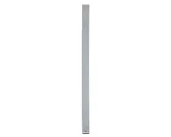
VSA series is made of multi-amplified vertical steerable arrays that represent one of the latest
RCF applications in terms of digital audio technology.
The 3 available models have similar features, but:
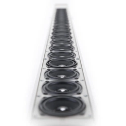
- VSA 2050 is the top model and includes 20 amplifiers and 20 full-range 3.5” RCF
transducers, its vertical dispersion is controlled up to 10° from 150 Hz and up.
- VSA 1250 includes 12 amplifiers and 12 full-range 3.5” RCF transducers, its vertical
dispersion is controlled up to 10° from 300 Hz and up.
- VSA 850 includes 8 amplifiers and 8 full-range 3.5” RCF transducers, its vertical
dispersion is controlled up to 10° from 500 Hz and up.
The internal digital signal processor processes the audio signal sent to each single internal
transducer in order to control the overall vertical acoustic dispersion.
VSA series speakers are the ideal for indoor installations, where a critical acoustic environment
can be an issue and a moderate visual impact is required, for instance: houses of worship,
airports, railway stations, auditoriums, congress halls, sport halls, shopping malls, etc. .
Unlike traditional sound columns, VSA speaker calibration is carried out electronically via
either RdNet software or its VSA SMART RC remote control for smartphones (to be purchased
separately and necessary, as it also includes the USB / RS 485 cable adapter with RJ45 connector
for linking to a computer), by specifying the installation height above the floor and the listening
area (or the maximum distance from speakers to audience).
The signal is fully processed and amplified in the digital domain, thanks also to 6 FPGAs (‘Field
Programmable Gate Array’) that manage all the data inside the speaker system.
The circuitry is modular to get maximum reliability and easy servicing.
VSA speakers include 2 independent power supply units, controlled by a microprocessor for
either AC (230 / 115 V) or DC (24 V) operation, to get full back-up facility when the product is
intended for emergency purposes.
Each internal circuit is monitored (voltage, current and temperature).
VSA series speakers meet all requirements needed by sound systems for emergency purposes.
One of the most important feature of the VSA digital arrays is their simple configuration, thanks
to RdNet software or its VSA SMART RC remote control for smartphones.
In a few steps, it is possible to tilt down and shape the acoustic beam in a virtual way, while the
column speaker is installed in a physical vertical position.
This configurability permits to address the audio signal exactly to the listening area, avoiding to
send acoustic energy to ceilings and empty floors, thus not introducing additional bad reflections
that would affect speech intelligibility, mainly in critical environments with high reverberation
time.
20 ‘class D’ amplifiers (50 W each, with high capacity power supply) for the VSA 2050 model, 12
for VSA 1250 and 8 for VSA 850, assure the best possible control and dynamics.
Each cabinet has four LEDs (AC, DC, FAULT and PRIORITY) and provides dry contacts (of an
internal relay) for remote ‘fault’ indication.
Thanks to a sophisticated algorithm developed by RCF, the focus control is not strictly necessary
as the best possible result is guaranteed overall the covered listening areas.
It is possible to set the acoustical coverage (tilt and beam) according to installation height and
the listening area to be served.
7
ENGLISH
Each speaker has 2 audio inputs, of which one has priority.
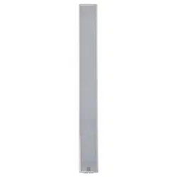
VSA speakers can be installed very close to the wall (to be unobtrusive) thanks to their compact
sizes, slim shapes and their (included) wall mounting accessories.
AC VSA S-BR optional accessory: each kit includes a pair of swivel brackets for a single VSA
speaker wall mounting, allowing a horizontal angle pointing up to 60°.
Connections are separated: AC and DC power supply at one end, audio signals and interfaces
on the other. The electrical connections are clearly labelled and made through screw terminals
and other suitable and easy-to-wire connectors.
VSA series (standard version) is intended for indoor sound systems only.
INSTALLATION
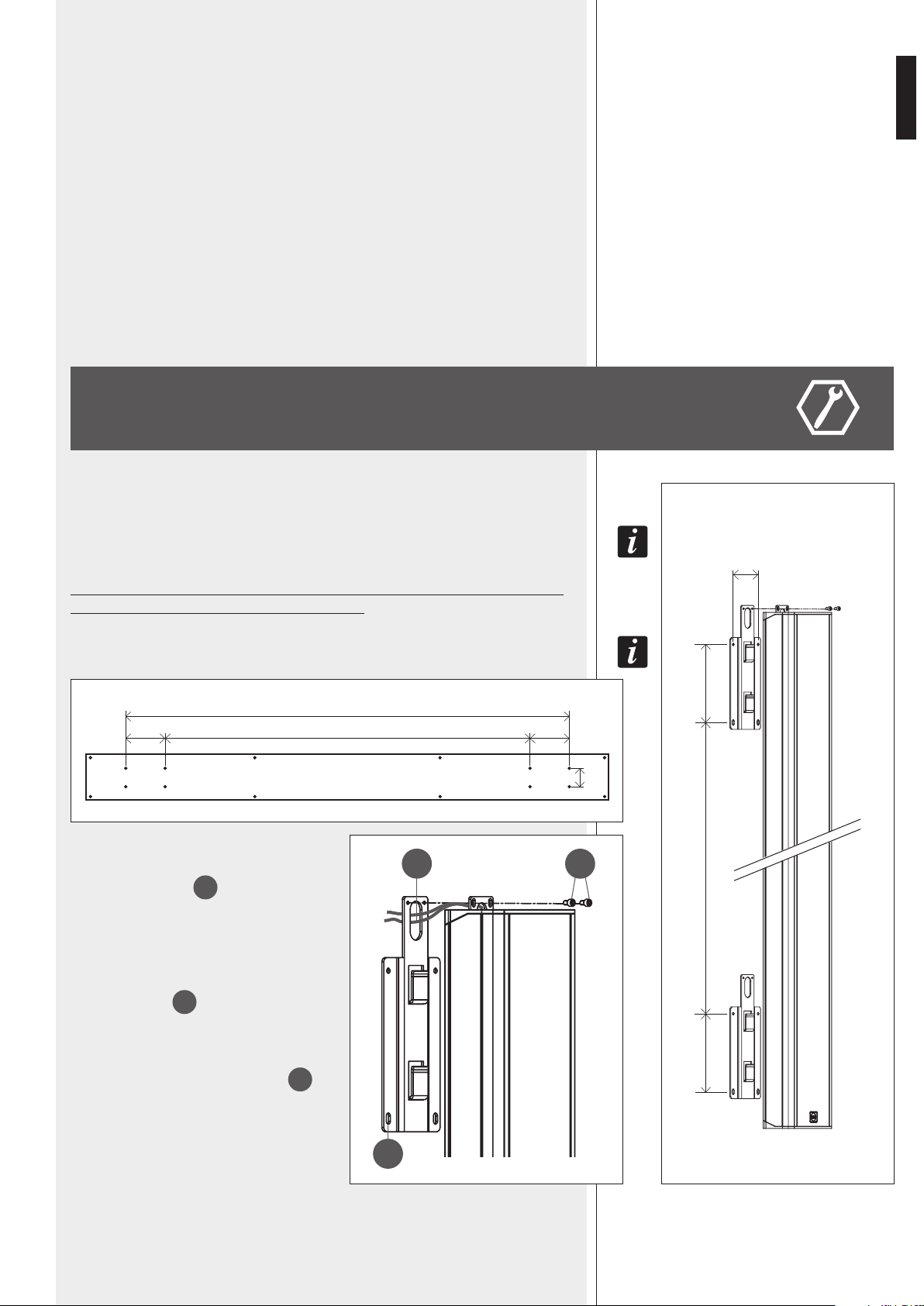
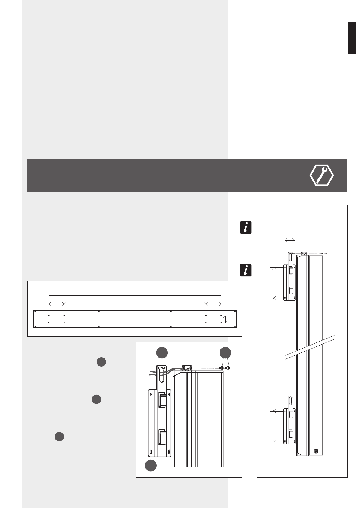
The speaker shall be wall-mounted through the two included brackets (picture 1).
To swivel iT wiTh a horizonTal angle up To 60°, iT is necessary To purchase The opTional
AC VSA S-BR accessory kiT.
Minimum installation height: the speaker bottom shall be at least 1 m from
the floor (suggested height: from 1.5 to 3 m).
The wood package lid can also be used as drilling TemplaTe (picTure 2)!
Each bracket shall be fixed to the wall by 4
dowels for 5 mm screws (passing through the 4
holes, see picture 3 –
A
).
If put to recessed pipelines, the power cables
(230-115 V ac and, separately, 24 V dc) can
pass through the bracket and the loudspeaker
holes (picture 3 –
B
).
Put the speaker on the bracket hooks and fix
it with the security screws (picture 3 –
C
),
which prevent the speaker might accidentally
slip off and fall.
A
B
C
PICTURE 3 PICTURE 1
PICTURE 2
1910 (VSA 2050), 1202 (VSA 1250), 848 (VSA 850)
170 170
80
80
170170 1570 (VSA 2050), 862 (VSA 1250), 508 (VSA 850)
1570 (VSA 2050), 862 (VSA 1250), 508 (VSA 850)
[mm]
[mm]
8
ENGLISH
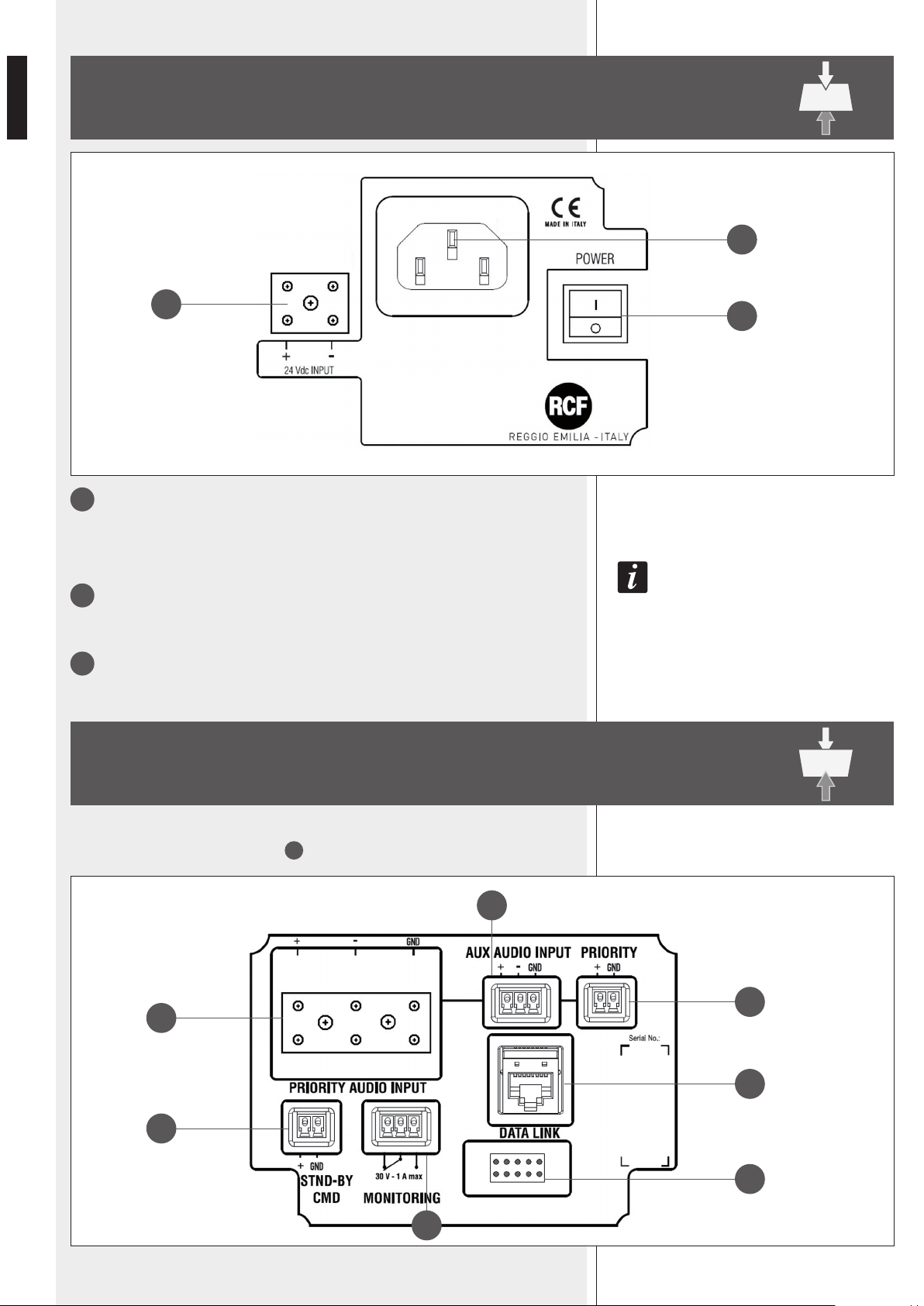
1
POWER
Main power switch.
I : ON O : OFF
afTer Turning The speaker on, The sysTem Takes abouT 15 seconds (‘sTarT-up’) To geT fully operaTing.
2
Socket for the power cord.
Before powering up, make sure the mains voltage corresponds to the voltage
indicated on the unit label.
3
24 Vdc INPUT
Secondary power supply input (24 V dc).
TOP PANEL (power supply)
BOTTOM PANEL (signals and commands)
4
7
6
9
10
5
8
1
2
3
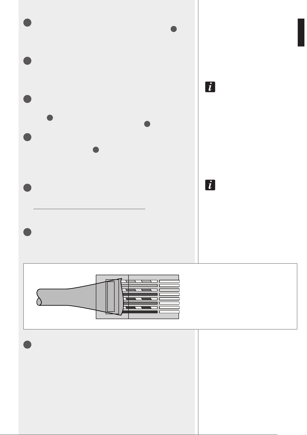
Remove the bottom panel cover with the 4 LEDs to access to connections (by disconnec-
ting its cable from the respective port
10
).
9
ENGLISH
4
PRIORITY AUDIO INPUT
Main audio input that can be enabled by the remote control or the PRIORITY
6
command.
The ceramic terminal allows its use in sound systems for emergency purposes.
+ (hot) signal, – (cold) signal, GND ground
5
AUX AUDIO INPUT
Auxiliary audio input (with removable plug) that can be enabled by the remote control.
+ (hot) signal, – (cold) signal, GND ground
only an audio inpuT can be open aT a Time. iT is noT possible To mix 2 inpuT signals.
6
PRIORITY
Priority command input, activated when the + and GND pins are short-circuited.
The priority function is mainly for emergency: when activated, the PRIORITY AUDIO
INPUT
4
gets open (the aux input gets muted) regardless the remote control
settings, the speaker is forced on if the stand-by command
7
is present, the
volume is set to its maximum level.
7
STND-BY CMD
Stand-by command input, activated when the + and GND pins are short-circuited.
It has no effect if the PRIORITY
6
command is present.
The speaker has also an auTomaTic sTand-by mode afTer ca. 30 minuTes wiThouT deTecTing any
audio signal. when in auTomaTic sTand-by mode, The speaker will auTomaTically Turn on as soon
as an audio signal is deTecTed on The selecTed inpuT.
8
MONITORING
Dry contacts (normally-closed, common, normally-open) of an internal relay that can
be used for ‘faulty’ remote indication.
This relay is activated when the speaker is working properly.
During any fault (or the speaker is switched off), the relay is deactivated.
Max. current applicable on contacts: 1 A. Max. voltage applicable on contacts: 30 V.
9
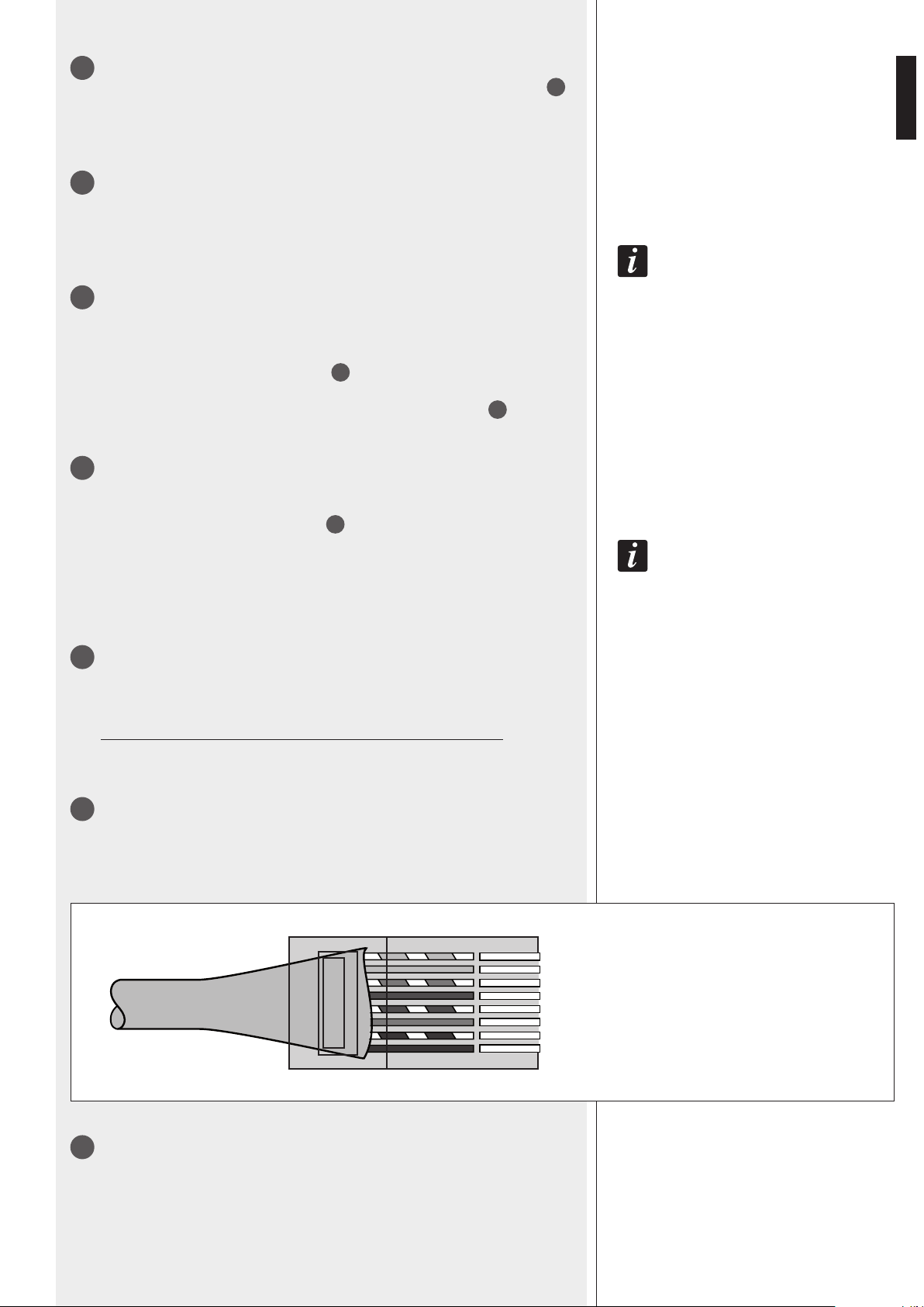
DATA LINK
RJ 45 port to link to a computer USB port for configuration via RdNet software (the
cable is included in the VSA SMART RC kit).
The standard is RS 485:
10
Port to connect the bottom panel cover with the 4 LEDs.
1. Orange/White
2. Orange
3. Green/White
4. Blue
5. Blue/White
6. Green
7. Brown/White
8. Brown
—
—
— A
— B
PINS
] GROUND
-1
-2
-3
-4
-5
-6
-7
-8
10
ENGLISH
LEDS ON THE BOTTOM PANEL COVER
during The speaker sTarT-up (afTer swiTching on, ca. 15 seconds) all The 4 leds are flashing.
From left to right:
1 AC (green)
When lit: AC power supply (mains: 230 / 115 V) is present and the speaker is operating.
2 DC (green)
When lit: 24 V DC power supply is present and the speaker is operating.
If batteries are not connected (or not available) or the voltage is lower than the minimum
threshold, this LED will be off.
if boTh AC and DC leds (only) are flashing, The speaker is in sTand-by mode.
3 FAULT (yellow)
When lit: a fault has been detected.
4 PRIORITY (red)
When lit: the priority function (of the PRIORITY AUDIO INPUT
4
) is activated by the
respective contact
6
.
LEDS ON THE BOTTOM PANEL
COVER
NOTES ABOUT THE RDNET SOFTWARE
RDNET SOFTWARE INSTALLATION
The RDNET software is protected by international copyright laws and is to be used to
configure the RCF RDNET system devices only.
It is not allowed to modify or change or try to decompile this software.
In no event shall RCF S.p.A. be liable to end-users for any damage whatsoever, including
but not limited to financial damages for loss of business profits or business information
due to the software use or inability to use this product.
The foregoing provision is effective even if RCF S.p.A. has been advised of the possibility
of such damages.
Even if the SOFTWARE has any material, verifiable and reproducible program errors, RCF
S.p.A. shall have no obligation to modify such errors.
MiniMuM RequiReMent: a PC with either MiCrosoft ‘windows® Vista’ or ‘7’
(or later) oPerating systeM, haVing an aVailable Usb Port.
Before installing a new software release, it is necessary to remove the previous
version (if installed). Verify also that the new release is the right one for the PC
operating system: either 32-bit or 64-bit.
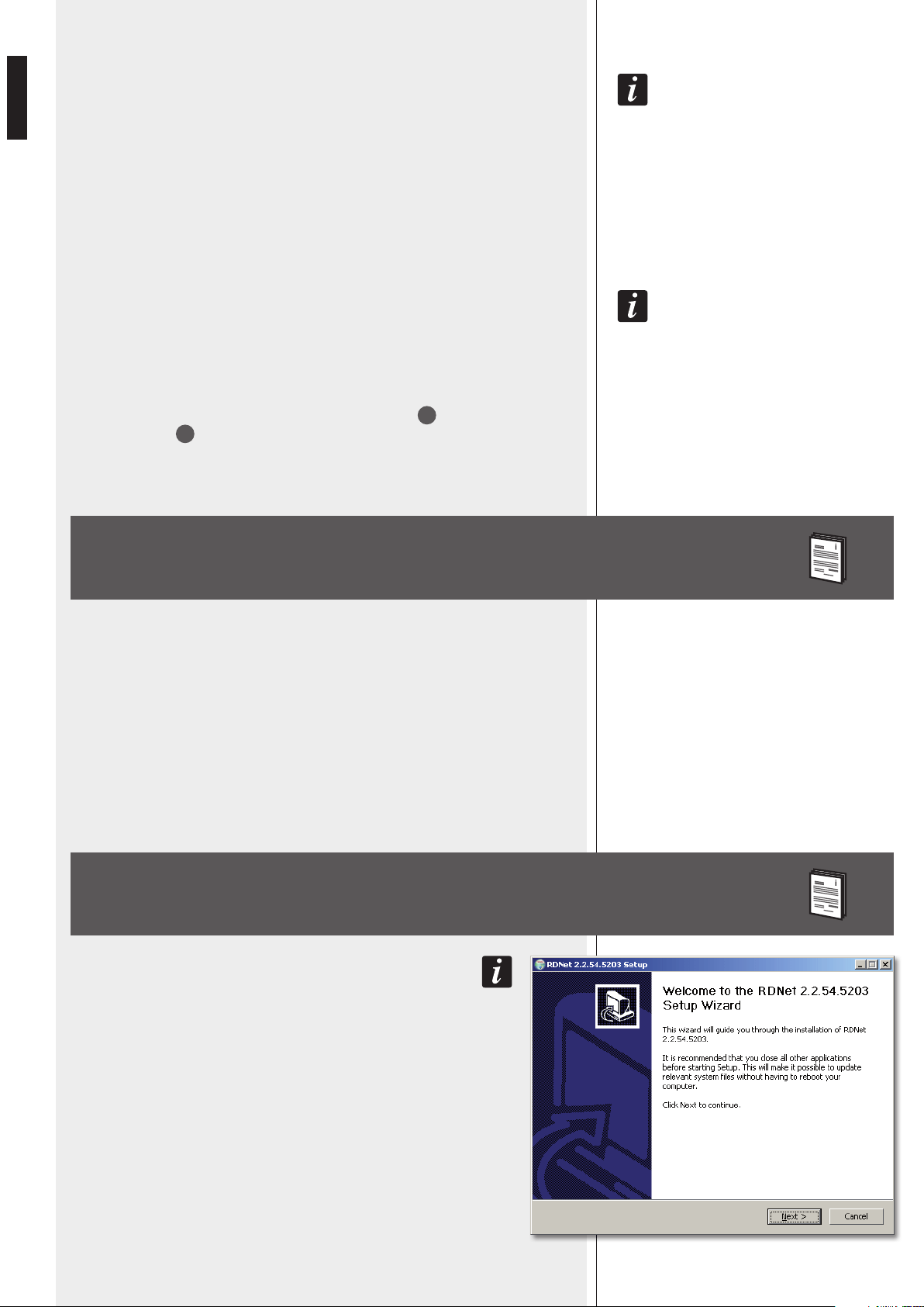
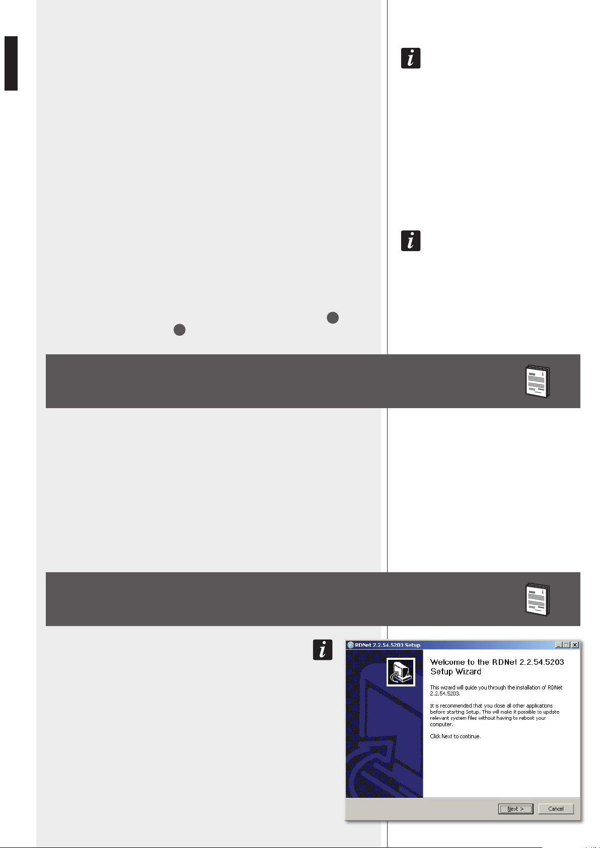
Run rcf_rdnetsetup_(versione).exe to start the setup wizard.
Click NEXT > to proceed.

11
ENGLISH
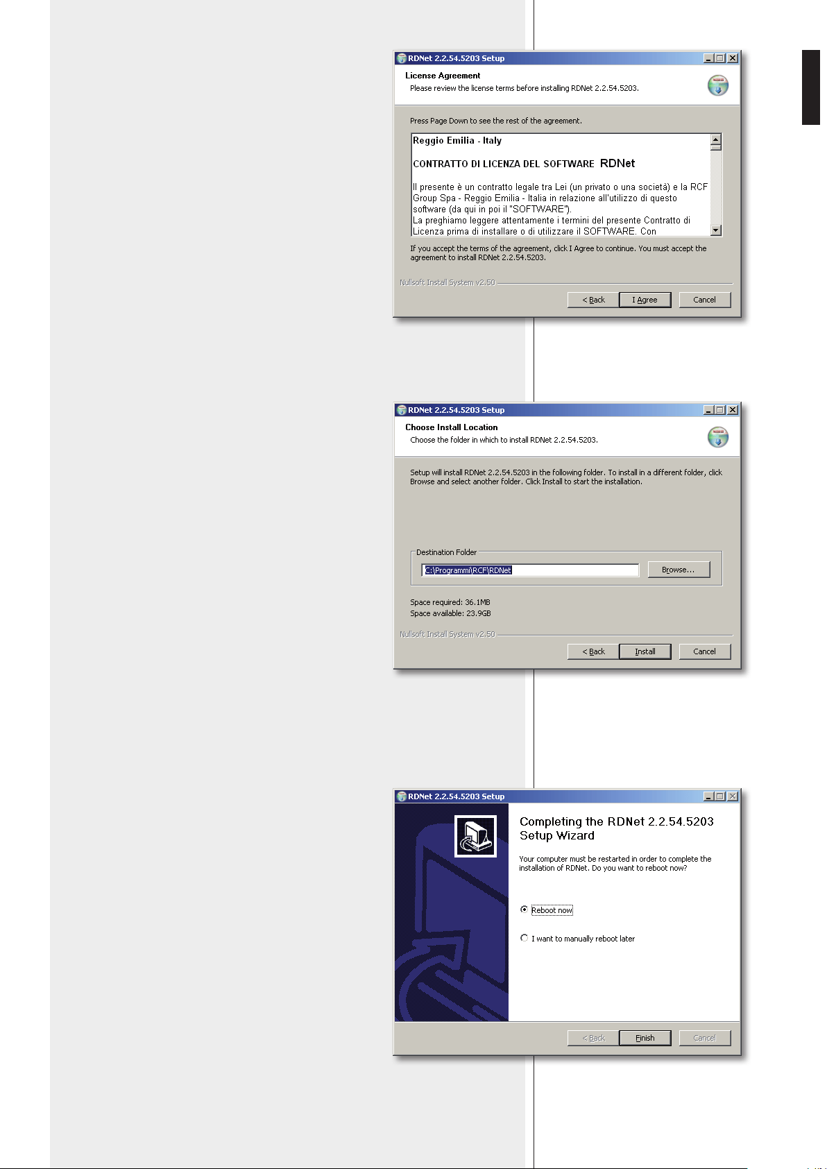
Read the license agreement.
Click ‘I Agree’ to accept and proceed with the
software installation.
It is now possible to change the installation
folder (directory) of the RDNET software (or keep
the default path).
Click INSTALL to proceed.
As soon as the installation ends, it will be necessary to
reboot your computer.
Choose either ‘Reboot Now’ to reboot immediately or ‘I
want to reboot later’ to reboot later manually.
Click FINISH to quit.
12
ENGLISH
Link the computer USB port to the VSA speaker DATA LINK
9
input by using the cable included in the VSA SMART RC kit.
Run the RDNET software (in Windows, click):
Start > Programs > RCF > RDNet > RDNet
(or double-click RDNet icon on the desktop).
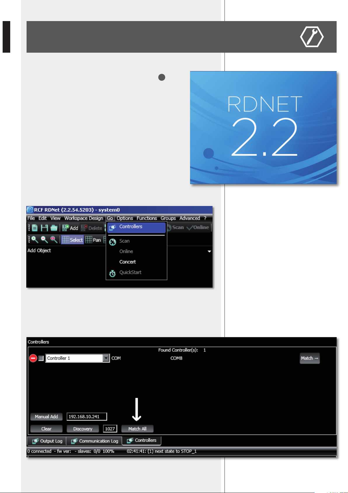
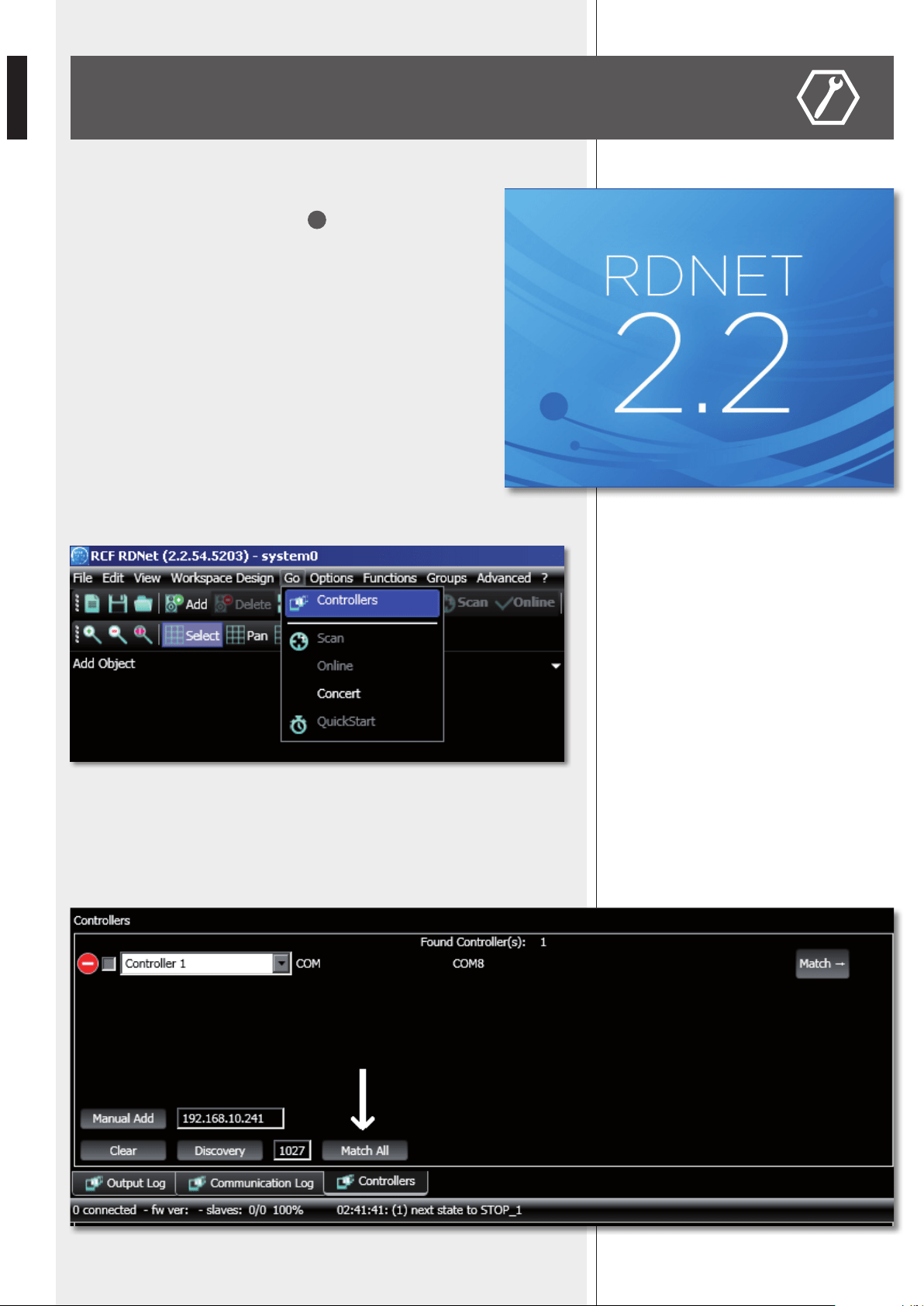
First, in the main menu, click ‘Go’ and then ‘Controllers’.
In the ‘Controllers’ section (bottom left in the main window), click ‘Match All’ (or click
each single ‘Match’ button or simply drag and drop) to add all linked USB devices (COM)
to the ‘Workspace Controllers’ list (bottom right in the main window).
CONFIGURATION BY RDNET SOFTWARE

13
ENGLISH
In the main menu, now click ‘Quickstart’: in the bottom right-hand corner of the main
window (in the bottom bar) the word ‘OFFLINE’ becomes ‘ONLINE’.
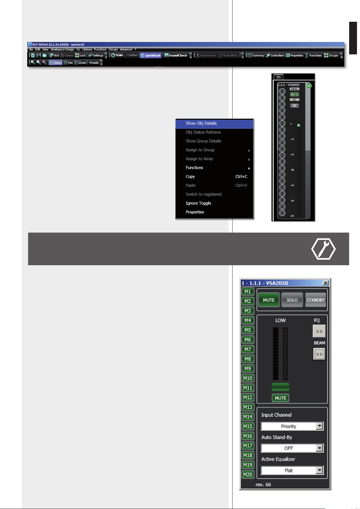
The detected VSA speaker module now appears (e.g. VSA 2050).
The ‘√’ symbol (on green background) indicates that the VSA speaker has been properly
connected (while the ‘–’ symbol on red background indicates ‘not detected’ / ‘not present’).
To open and edit the VSA setup window, point the PC mouse on
the VSA module and double-click
(or right-click and select ‘Show Obj Details’)
To upgrade the VSA speaker firmware
(main menu: “Advanced > Firmware Upgrade...”).
Refer to the RDNET user manual for all software functions.
MUTE
Click MUTE to mute the VSA speaker (all MUTE buttons get red). Click MUTE again to
unmute.
SOLO
This function is useful only when an RdNet network with several speakers is present
(through either a RDNET CONTROL 8 or CONTROL 2 device). Read the RdNet software
user manual.
Click SOLO to make the selected VSA speaker the only one activated, while the others are
muted.
STANDBY
Stand-by mode.
M1 to M20 buttons (on the left).
VSA test mode that allows to listen to each single transducer.
Click one of the M1 – M20 buttons (relative to each single transducer) for solo listening.
Click either it again to reset the normal operation or another one to keep testing.
Green: unmuted, red: muted.
EQ: click EQ to open and edit the equalizer window (relative to the three custom
equalizations), which includes both Gain and Delay settings as well.
BEAM: click BEAM to open and edit the beam setting window.
SETUP WINDOW
14
ENGLISH
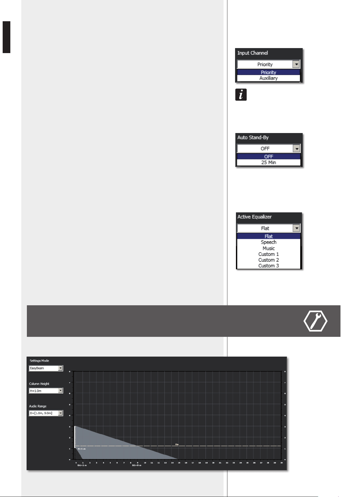
INPUT CHANNEL
Input channel selection:
- PRIORITY PRIORITY AUDIO INPUT is open
(AUX AUDIO INPUT is muted).
- AUXILIARY AUX AUDIO INPUT is open
(PRIORITY AUDIO INPUT is muted).
the aUXiliary seleCtion has no effeCt when the Priority fUnCtion of the Priority aUdio inPUt
is aCtiVated.
AUTO STAND-BY
If set to 25 Min, VSA speakers will automatically turn off (stand-by) after 25 minutes
without detecting any audio signal and turn on as soon as an audio signal is detected on
the selected input (or due to the activation of the priority function).
Set AUTO STAND-BY to OFF to disable this function.
ACTIVE EQUALIZER
The equalization can be chosen among 6 different settings: 3 are presets and 3 are editable
by the user (custom 1, 2, 3).
- FLAT no equalization (flat frequency response)
- SPEECH equalization optimized for speech
- MUSIC equalization optimized for music
- CUSTOM 1 – 2 – 3 3 custom equalizations by setting max. 8 filters
BEAM SETTING WINDOW
Click BEAM to open and edit the beam setting window.
15
ENGLISH
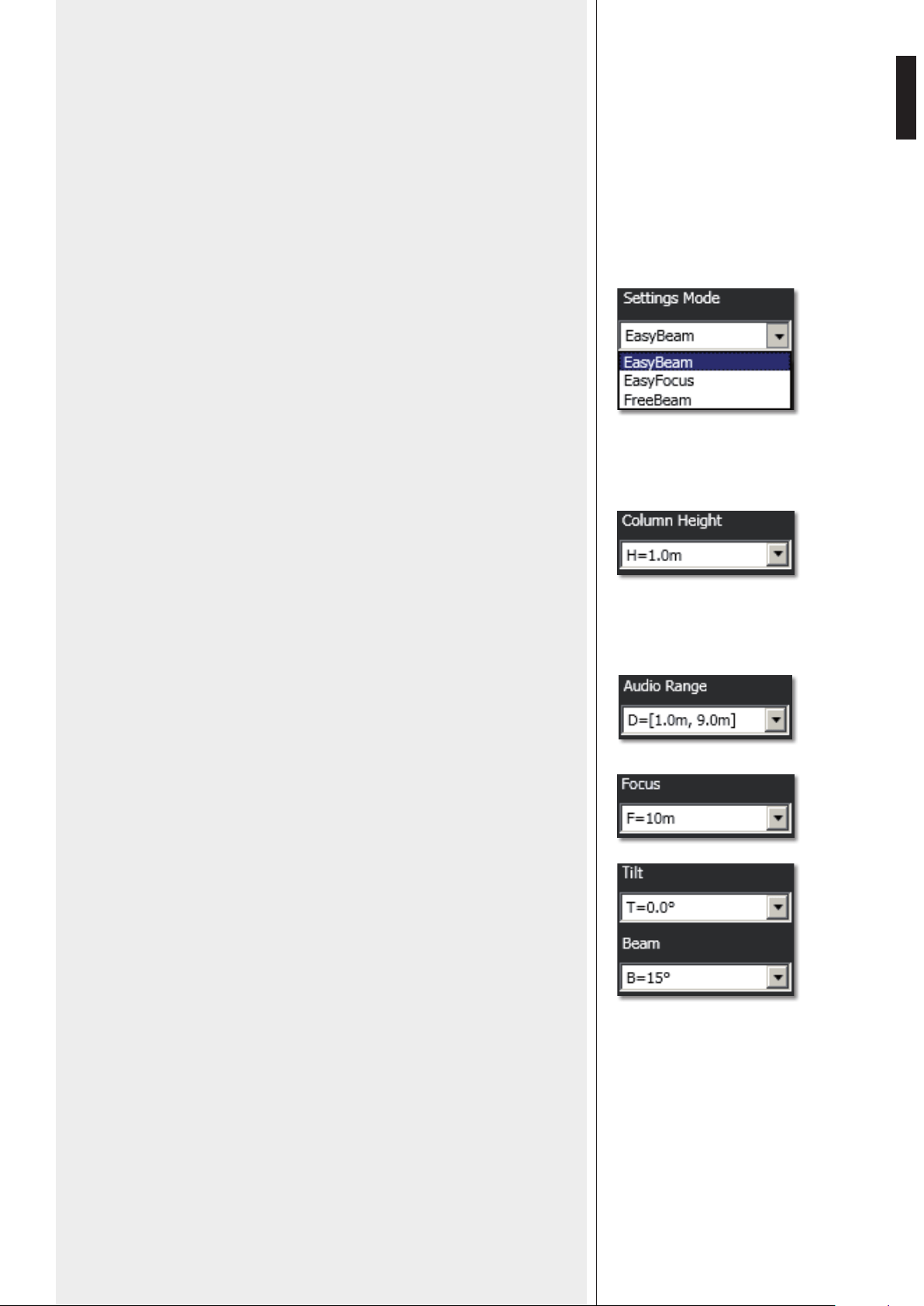
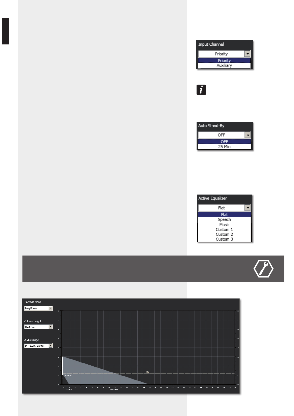
Values represented graphically:
- H: speaker bottom installation height
- Ha: considered listening area height (1.2 m)
- In EASY BEAM mode, the minimum D1 and maximum D2 distances of the listing area
from the speaker
- In EASY FOCUS mode, the maximum distance F to be covered
- In FREE BEAM mode, the tilt T (vertical angle downwards) and the beam B (vertical
dispersion).
2. Set the speaker installation height (considering the distance from its bottom to the
floor) by clicking COLUMN HEIGHT.
The range is from 1 to 6 metres (0.1 m steps) in the EASY BEAM mode, from 1.5 to 3
metres (0.5 m steps) in the EASY FOCUS mode, from 2 to 6 metres (0.1 m steps) in the
FREE BEAM mode.
3a. (EASY BEAM) Set the listening area D through AUDIO RANGE.
Both minimum D1 and maximum D2 distances (from speaker) can be selected among
several presets according to the speaker height H.
3b. (EASY FOCUS) Set the maximum distance to be covered through FOCUS.
3c. (FREE BEAM) Set the TILT and then the BEAM.
1. First, select the SETTINGS MODE:
- EASY BEAM allows to specify the listening area to be covered by selecting a preset
audio range.
- EASY FOCUS, simple, easy and suitable for all systems, advisable for users and
installers that are not so expert. Only two values are necessary: the speaker installation
height and the maximum distance to be covered.
- FREE BEAM, for expert users / installers, it allows the (virtual) setting of both speaker
tilt and beam.

16
ENGLISH
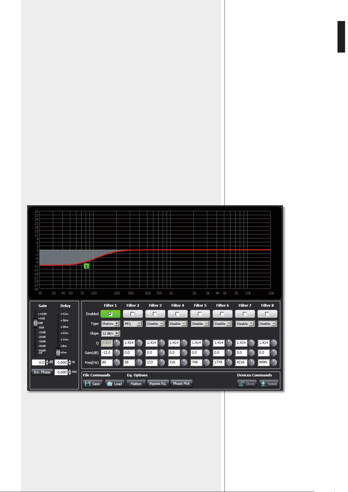
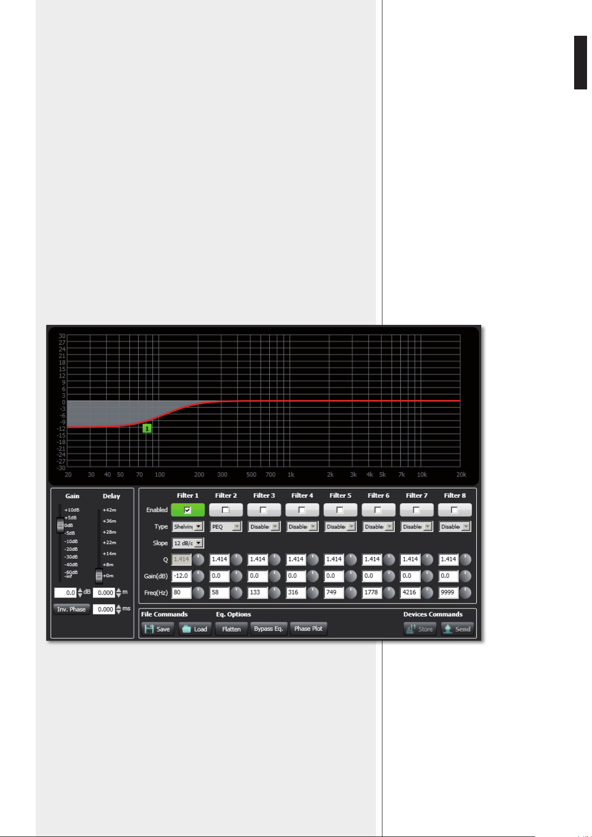
EQUALIZER SETTING WINDOW
Click EQ to open and edit the equalizer window (relative to the three custom equalizations),
which includes both Gain and Delay settings as well.
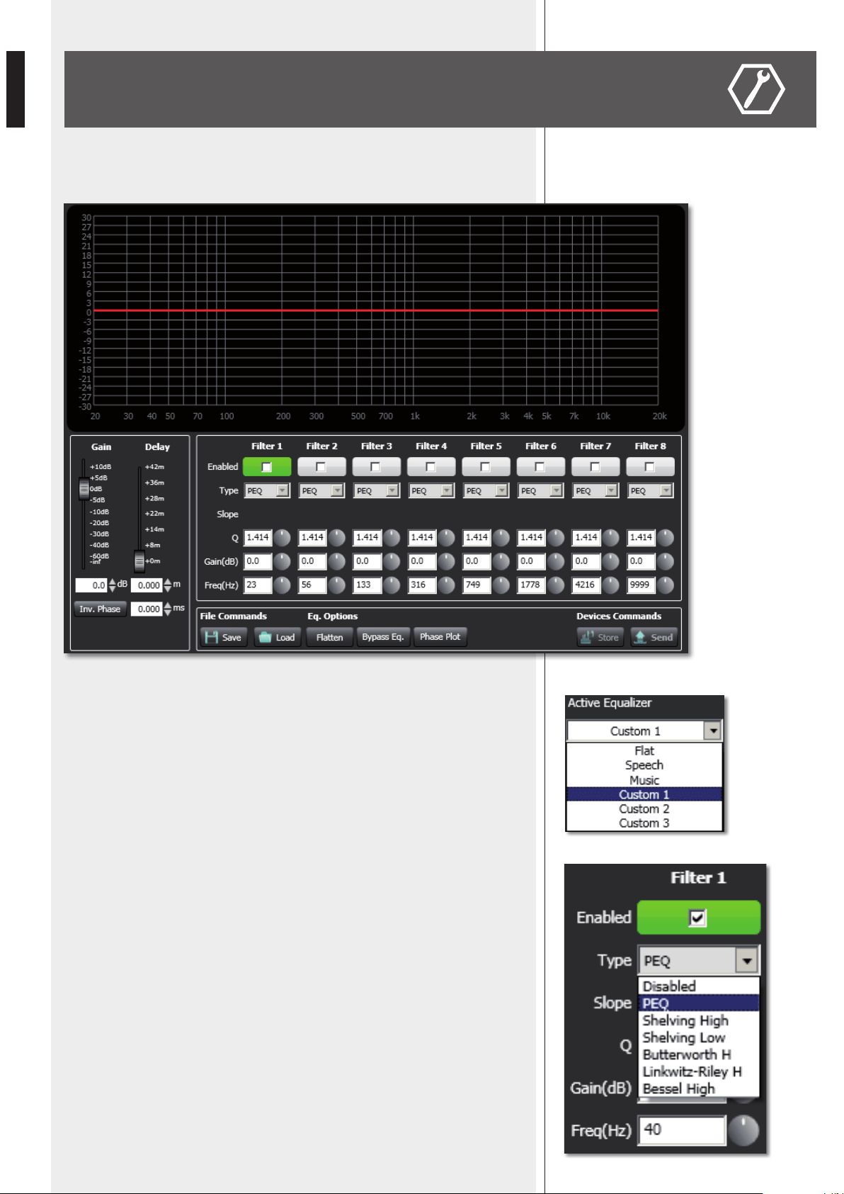
First, in the Active Equalizer option menu, choose one of the three custom equalizations
CUSTOM 1 – 2 – 3 to edit.
It is possible to set up to eight independent filters (Filter 1, 2, 3, 4, 5, 6, 7, 8).
Enabled: click the checkbox to toggle each filter.
Move the mouse on its white background (making it green) to highlight a filter (if present) on
the EQ graph.
Type:
- DISABLED: the filter is disabled (by-pass).
- PEQ: parametric equalizer that allows to adjust the level at the settable centre frequency and
specify the Q factor (the adjusted level can be widened or narrowed).
- SHELVING HIGH: increase or decrease the level of all frequencies above the selected
frequency by the specified amount.
- SHELVING LOW: increase or decrease the level of all frequencies below the selected frequency
by the specified amount.
- The BUTTERWORTH, LINKWITZ-RILEY, BESSEL options are only available for the filters
no.1 (‘high-pass’) and no.8 (‘low-pass’).
Slope: filter slope setting (dB / oct).
Q: Q factor setting.
Gain (dB): filter gain setting.
Freq (Hz): either filter frequency selection or PEQ central frequency setting.
17
ENGLISH
File Commands:
- SAVE: it saves to PC the current equalization as .rde file.
- LOAD: it loads from PC an equalization previously saved as .rde file.
Eq. options:
- FLATTEN: it disables all filters (flat frequency response).
- BYPASS EQ.: it disables the equalization, but without changing filter settings.
- PHASE PLOT: if selected, the phase plot is shown (green line).
Devices commands:
- STORE: it sends and stores the equalization to the VSA speaker.
- SEND: it sends (without storing) the equalization to the VSA speaker.
For each filter, frequency and gain can be adjusted either graphically (through the mouse) by
dragging the little coloured square or in an analytical way (by inserting values in cells or rotating
controls).
The overall equalization is shown as a red line, the intervention of the selected filter as a green
line, the intervention of a filter that is not selected as a white line.
For example, to apply a 12 dB attenuation for frequencies below 80 Hz: enable the filter 1 by
clicking its ‘Enabled’ checkbox, select the SHELVING LOW filter type, set the gain to –12 dB and
frequency to 80 Hz .
18
ENGLISH
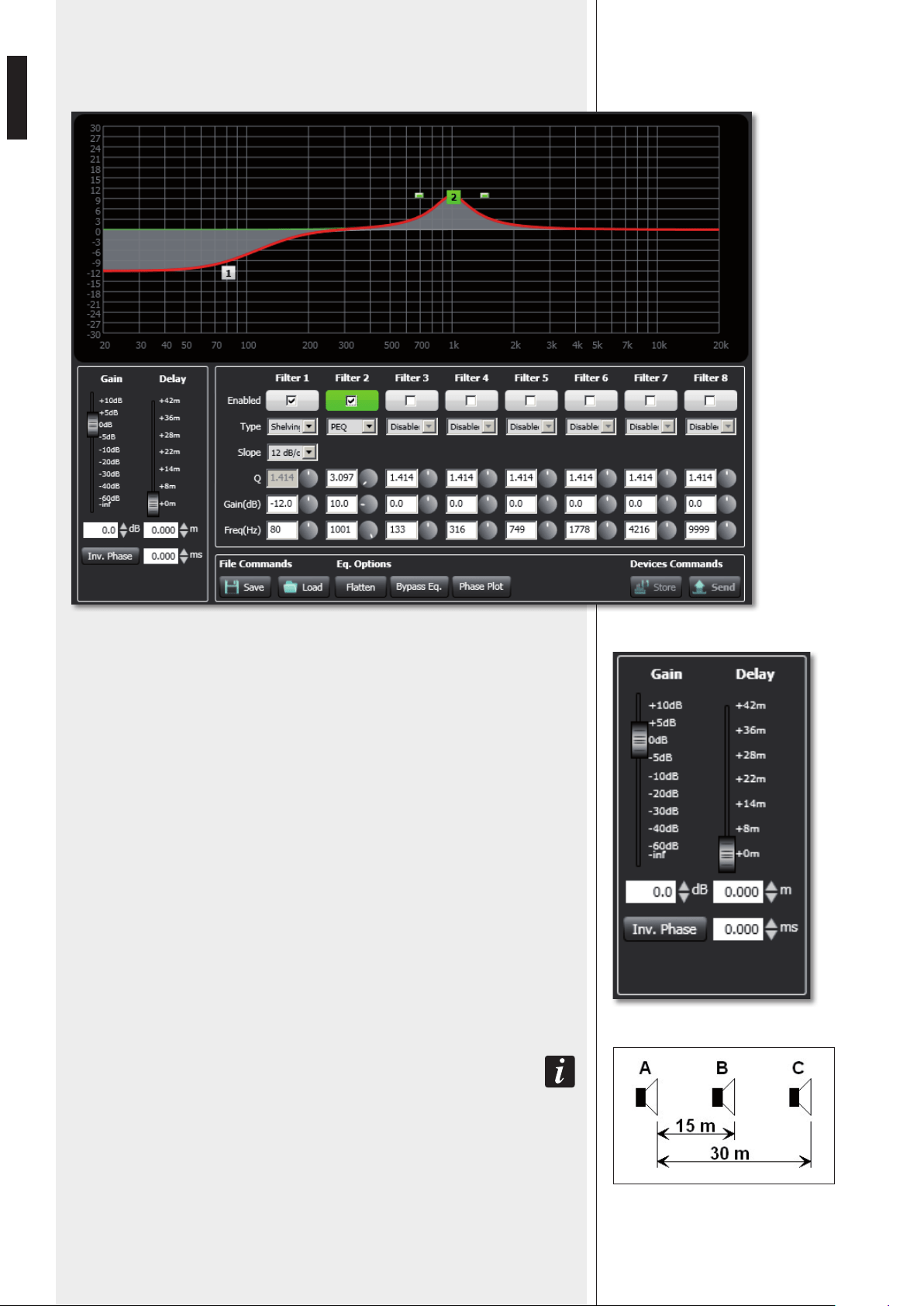
To add a second filter (i.e. PEQ): enable the filter 2, select the PEQ filter type, its gain and
central frequency, then set its Q factor.
INV. PHASE
If selected (red light), the VSA speaker phase is inverted.
Finally, click either STORE (send and store) or SEND all EQ settings (without storing) to
the VSA speaker.
GAIN
Gain setting (dB) of all the audio range (0 = flat).
DELAY
Delay line setting.
If the sound system is made of two or more speaker lines, it is advisable to delay the sound
from the second line onwards (setting a delay time directly proportional to the distance
from the first speaker line), in order to reduce the perception of echo (due to the different
reception times of sounds coming from speakers that are distant one another), give a
correct sense of depth to listeners and improve the speech intelligibility.
You can set the distance in meters (graphically or analytically) or the time in milliseconds
(by entering the numeric value only).
eXaMPle (see the figUre):
- the b sPeaker is 15 Metres far froM the a sPeaker (first line) and needs to be delayed by
setting the delay ParaMeter to 15 m.
- the C sPeaker is 30 Metres far froM the a sPeaker (first line) and needs to be delayed by setting
the delay ParaMeter to 30 m.
19
ENGLISH
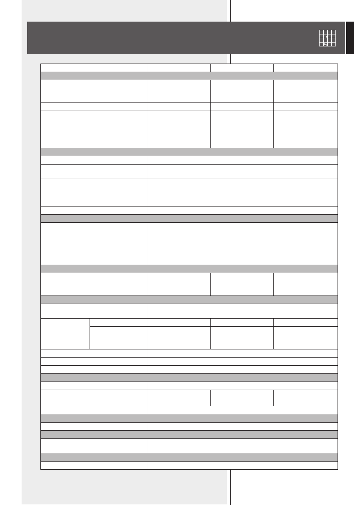
SPECIFICATIONS
VSA 2050 VSA 1250 VSA 850
ACOUSTICAL SPECS.
Frequency response 100 Hz ÷ 18 kHz 120 Hz ÷ 18 kHz 130 Hz ÷ 18 kHz
Max. sound pressure level
(A-weighted at 30 m)
96 dB 94 dB 93 dB
Horizontal coverage angle 130° 130° 130°
Vertical coverage angle selectable from 10° to 30° selectable from 10° to 30° selectable from 10° to 30°
Vertical steering angle selectable from 0° to –40° selectable from 0° to –40° selectable from 0° to –40°
Transducers
20 x 3.5”
full-range loudspeakers
12 x 3.5”
full-range loudspeakers
8 x 3.5”
full-range loudspeakers
INPUT SECTION
Input sensitivity 0 dBu
Connectors
balanced screw terminals
balanced ceramic screw terminal
Controls
remote control infrared port
priority command
remote ‘fault’ indication
stand-by remote command
LEDs Power supply, fault, priority
PROCESSOR
Type
Texas TMS320C6726
32-bit floating point DSP
Spartan3A FPGA
24 bit AD converters, 48 kHz
Operation
20 PEQ channels, compression, beam forming,
20 limiters and protections
AMPLIFIERS
Type 20 ‘class D’ amplifiers 12 ‘class D’ amplifiers 8 ‘class D’ amplifiers
Power (each amplifier) 50 W 50 W 50 W
POWER SUPPLY
AC power supply
either 230 V or 115 V (according to the model),
50 – 60 Hz, type: ‘switching’
Consumption
stand-by 26 W 21 W 18 W
operating,
no signal
66 W 46 W 36 W
max. power 600 W 600 W 400 W
Internal fuse (AC) T3.15AL/250 V (230 V); T6.3AL/250 V (115V)
Secondary DC power supply 24 V
DC power in connector ceramic screw terminal
PHYSICAL SPECS.
Cabinet material aluminium (powder coated)
Dimensions (w, h, d) 125, 2070, 97 mm 125, 1340, 97 mm 125, 980, 97 mm
Net weight 19 kg 14 kg 10 kg
Colour RAL 9002 (grey white)
INCLUDED ACCESSORIES
Installation 2 wall-mounting brackets
REQUIRED ACCESSORY TO BE PURCHASED SEPARATELY
Remote control for smartphone with the
USB / RS 485 cable to link to PC
VSA SMART RC
OPTIONAL ACCESSORY
Installation with a
horizontal angle up to 60°
AC VSA S-BR

20
ITALIANO
IMPORTANTE
ATTENZIONE
AVVERTENZE PER
LA SICUREZZA
IMPORTANTE
Prima di collegare ed utilizzare questo prodotto, leggere attentamente le istruzioni
contenute in questo manuale, il quale è da conservare per riferimenti futuri.
Il presente manuale costituisce parte integrante del prodotto e deve accompagnare
quest’ultimo anche nei passaggi di proprietà, per permettere al nuovo proprietario di
conoscere le modalità d’installazione e d’utilizzo e le avvertenze per la sicurezza.
L’installazione e l’utilizzo errati del prodotto esimono la RCF S.p.A. da ogni responsabilità.
ATTENZIONE: Per prevenire i rischi di fiamme o scosse elettriche, non esporre mai questo
prodotto alla pioggia o all’umidità.
AVVERTENZE PER LA SICUREZZA
1. Tutte le avvertenze, in particolare quelle relative alla sicurezza, devono essere lette con
particolare attenzione, in quanto contengono importanti informazioni.
2.1 - ALIMENTAZIONE PRINCIPALE DA RETE ELETTRICA
- La tensione di alimentazione dell’apparecchio ha un valore sufficientemente alto da
costituire un rischio di folgorazione per le persone: non procedere mai all’installazione
od alla connessione dell’apparecchio con il cavo dell’alimentazione collegato alla rete
elettrica.
- Prima di alimentare questo prodotto, assicurarsi che tutte le connessioni siano corrette
e che la tensione della vostra rete di alimentazione corrisponda quella di targa
dell’apparecchio, in caso contrario rivolgetevi ad un rivenditore RCF.
- Le parti metalliche dell’apparecchio sono collegate a terra tramite il cavo di alimentazione.
Un apparecchio avente costruzione di CLASSE I deve essere connesso alla presa di rete
con un collegamento alla terra di protezione.
- Accertarsi che il cavo di alimentazione dell’apparecchio non possa essere calpestato o
schiacciato da oggetti, al fine di salvaguardarne la perfetta integrità.
- Per evitare il rischio di shock elettrici, non aprire mai l’apparecchio: all’interno non vi
sono parti che possono essere utilizzate dall’utente.
2.2 - ALIMENTAZIONE SECONDARIA 24 V c. c. TRAMITE BATTERIE
- L’apparecchio funziona con tensione 24 V in corrente continua (pertanto, occorre
collegare in serie più batterie aventi una tensione nominale inferiore, es. 2 x 12 V).
- Utilizzare sempre batterie ricaricabili, opportunamente scelte in funzione del massimo
carico possibile.
- Verificare che sia rispettata la polarità delle batterie.
- Non cortocircuitare le batterie (ad esempio collegando i 2 poli opposti con un filo di
metallo).
- Smaltire le batterie esaurite facendo riferimento alle norme di legge vigenti (nel paese
di utilizzo) in materia di ecologia e protezione dell’ambiente.
3. Impedire che oggetti o liquidi entrino all’interno del prodotto, perché potrebbero causare
un corto circuito. L’apparecchio non deve essere esposto a stillicidio o a spruzzi d’acqua;
nessuna sorgente di fiamma nuda (es. candele accese) e nessun oggetto pieno di liquido
(es. vasi) deve essere posto sull’apparecchio.
4. Non eseguire sul prodotto interventi / modifiche / riparazioni se non quelle espressamente
descritte sul manuale istruzioni. Contattare centri di assistenza autorizzati o personale
altamente qualificato quando:
- l’apparecchio non funziona (o funziona in modo anomalo);
- il cavo di alimentazione ha subito gravi danni;
- oggetti o liquidi sono entrati nell’apparecchio;
- l’apparecchio ha subito forti urti.
5. Qualora questo prodotto non sia utilizzato per lunghi periodi, scollegare il cavo
d’alimentazione dalla rete e/o le batterie.

21
ITALIANO
6. Nel caso che dal prodotto provengano odori anomali o fumo, spegnerlo
immediatamente e scollegare il cavo d’alimentazione e/o le batterie.
7. Non collegare a questo prodotto altri apparecchi e accessori non previsti.
Quando è prevista l’installazione sospesa, utilizzare solamente gli appositi punti di
ancoraggio e non cercare di appendere questo prodotto tramite elementi non idonei o
previsti allo scopo.
Verificare inoltre l’idoneità del supporto (parete, soffitto, struttura ecc., al quale è ancorato
il prodotto) e dei componenti utilizzati per il fissaggio (tasselli, viti, staffe non fornite da
RCF ecc.) che devono garantire la sicurezza dell’impianto / installazione nel tempo, anche
considerando, ad esempio, vibrazioni meccaniche normalmente generate da un trasduttore.
Per evitare il pericolo di cadute, non sovrapporre fra loro più unità di questo prodotto,
quando questa possibilità non è espressamente contemplata dal manuale istruzioni.
8. La RCF S.p.A. raccomanda vivamente che l’installazione di questo prodotto
sia eseguita solamente da installatori professionali qualificati (oppure da ditte
specializzate) in grado di farla correttamente e certificarla in accordo con le
normative vigenti.
Tutto il sistema audio dovrà essere in conformità con le norme e le leggi
vigenti in materia di impianti elettrici.
9. Sostegni e Carrelli
Se previsto, il prodotto va utilizzato solo su carrelli o sostegni consigliati dal produttore.
L’insieme apparecchio-sostegno / carrello va mosso con estrema cura. Arresti improvvisi,
spinte eccessive e superfici irregolari o inclinate possono provocare il ribaltamento
dell’assieme.
10. Quando si installa un sistema audio professionale, si devono considerare anche i fattori
meccanici ed elettrici (oltre a quelli prettamente acustici, come la pressione sonora, gli
angoli di copertura, la risposta in frequenza, ecc.).
11. Perdita dell’udito
L’esposizione ad elevati livelli sonori può provocare la perdita permanente dell’udito. Il
livello di pressione acustica pericolosa per l’udito varia sensibilmente da persona a persona
e dipende dalla durata dell’esposizione. Per evitare un’esposizione potenzialmente
pericolosa ad elevati livelli di pressione acustica, è necessario che chiunque sia sottoposto
a tali livelli utilizzi delle adeguate protezioni; quando si fa funzionare un trasduttore in
grado di produrre elevati livelli sonori è necessario indossare dei tappi per orecchie o delle
cuffie protettive.
Consultare i dati tecnici contenuti nei manuali istruzioni per conoscere le massime pressioni
sonore che i diffusori acustici sono in grado di produrre.
12. Collocare il prodotto lontano da fonti di calore e garantire la circolazione dell’aria
intorno.
13. Non sovraccaricare questo prodotto per lunghi periodi.
14. Non forzare mai gli organi di comando (tasti, manopole ecc.).
15. Non usare solventi, alcool, benzina o altre sostanze volatili per la pulitura delle parti
esterne dell’unità; usare un panno asciutto.
NOTA SUI CAVI PER SEGNALI AUDIO
Per evitare fenomeni di rumorosità indotta sui cavi che trasportano segnali dai microfoni o
di linea (per esempio 0dB), usare solo cavi schermati ed evitare di posarli nelle vicinanze di:
- apparecchiature che producono campi elettromagnetici di forte intensità;
- cavi della rete elettrica;
- linee altoparlanti.
22
ITALIANO
RCF S.P.A. VI RINGRAZIA PER L’ACQUISTO DI QUESTO PRODOTTO, REALIZZATO
IN MODO DA GARANTIRNE L’AFFIDABILITÀ E PRESTAZIONI ELEVATE.
DESCRIZIONE
La serie di diffusori a colonna multiamplificati VSA (“vertical steerable arrays”) rappresenta una
delle più recenti applicazioni RCF in termini di tecnologia audio digitale.
I 3 modelli disponibili hanno caratteristiche simili, tranne:
- VSA 2050 è il modello di punta avente 20 amplificatori e 20 altoparlanti RCF a gamma
estesa da 3,5”; la sua dispersione verticale è controllata fino a 10° da 150 Hz in su;
- VSA 1250 include 12 amplificatori e 12 altoparlanti RCF a gamma estesa da 3,5”;
la sua dispersione verticale è controllata fino a 10° da 300 Hz in su;
- VSA 850 include 8 amplificatori e 8 altoparlanti RCF a gamma estesa da 3,5”;
la sua dispersione verticale è controllata fino a 10° da 500 Hz in su.
Il processore digitale interno elabora il segnale audio inviato ad ogni singolo altoparlante per
controllare la dispersione verticale complessiva.
I diffusori della serie VSA sono l'ideale per installazioni fisse all’interno in ambienti acusticamente
critici e/o in luoghi dove vi sono particolari vincoli architettonici, come ad esempio: luoghi di
culto, sale d’attesa di stazioni ed aeroporti, metropolitane, auditorium, sale congressuali, palazzi
dello sport, nella gallerie all’interno di centri commerciali, ecc. .
A differenza delle colonne sonore di tipo tradizionale, la calibrazione dei diffusori della serie
VSA si effettua elettronicamente tramite il software RdNet oppure il telecomando VSA SMART
RC per smartphone (da acquistare separatamente e necessario, in quanto include anche il cavo
adattatore USB / RS485 con connettore RJ45 per il collegamento al computer), specificando
l'altezza d'installazione dal pavimento e la distanza massima da coprire o l'area d'ascolto.
Il segnale viene totalmente processato ed amplificato digitalmente grazie anche a 6 FPGA (“Field
Programmable Gate Array”: dispositivi digitali programmabili via software) che gestiscono tutti i
dati all’interno del diffusore. I circuiti elettronici sono modulari in modo da garantire la massima
affidabilità ed una manutenzione semplice.
I diffusori della serie VSA comprendono due diverse ed indipendenti modalità di alimentazione,
una in corrente alternata (230 / 115 V) ed una in corrente continua (24 V), in modo da garantire
piena continuità di servizio. È presente il controllo della tensione, corrente e temperatura in ogni
circuito.
Sono stati previsti e rispettati tutti i requisiti per utilizzare i diffusori della serie VSA in sistemi
audio con funzione di emergenza ed evacuazione.
Una delle caratteristiche più importanti dei diffusori della serie VSA è la semplicità di
configurazione tramite il software RdNet oppure il telecomando VSA SMART RC.
In pochi passi, è possibile orientare e dare forma in maniera virtuale al fascio acustico, anche se
il diffusore è fisicamente installato in posizione verticale.
Tale configurabilità permette di indirizzare il segnale audio esattamente verso l’area d’ascolto,
evitando di disperdere energia acustica verso il soffitto o zone vuote della platea, eliminando
così fastidiosi echi che potrebbero compromettere l’intelligibilità del parlato, soprattutto in
ambienti acusticamente difficili aventi un forte riverbero.
20 amplificatori in “classe D” (50 W ciascuno, con alimentazione ad alta capacità) nel modello
VSA 2050, 12 nel VSA 1250 e 8 nel VSA 850, assicurano il miglior controllo possibile e la miglior
dinamica del suono.
Sono presenti indicatori luminosi (LED) ed un relè per la segnalazione remota di eventuali guasti.
Grazie ad un sofisticato algoritmo sviluppato da RCF, il controllo di “messa a fuoco” del fascio
sonoro non è indispensabile in quanto il miglior risultato possibile è assicurato su tutte le aree
di ascolto.
23
ITALIANO
È possibile regolare su misura la copertura acustica (inclinazione verticale ed apertura) in base
all'altezza d'installazione del diffusore ed all’area d’ascolto da servire.
Ciascun diffusore dispone di 2 ingressi audio, dei quali uno con funzione di priorità.
Grazie alle loro forma di dimensioni compatte, i diffusori della serie VSA possono essere installati
a ridosso della parete (in modo da non risultare ingombrante) tramite i loro accessori (inclusi).
Il kit opzionale AC VSA S-BR include una coppia di staffe orientabili per l'installazione a parete
di un solo diffusore della serie VSA con un angolo orizzontale fino a 60°.
Le connessioni sono protette da appositi schermi: alimentazione AC e DC da una parte e segnali
audio e interfacce dall’altra. I collegamenti elettrici sono etichettati chiaramente e costituiti da
terminali a vite e connettori semplici da collegare.
La versione standard dei diffusori della serie VSA è adatta solo per applicazioni al chiuso.
INSTALLAZIONE
Il diffusore deve essere installato a parete tramite le due staffe in dotazione (figura 1).
per orienTare orizzonTalmenTe il diffusore con un angolo fino a 60°, è necessario acquisTare il
kiT opzionale AC VSA S-BR.
Altezza minima dell’installazione: la base del diffusore deve essere posta ad
almeno 1 m dal pavimento (altezza consigliata: da 1,5 a 3 m).
il coperchio della scaTola d’imballo (in legno) serve anche come dima di foraTura del muro
(figura 2)!
Ciascuna staffa deve essere fissata alla parete
tramite 4 tasselli per viti con diametro 5 mm
(passanti per i 4 fori; figura 3 –
A
).
I cavi per l’alimentazione (230-115 V c.a. e,
separatamente, 24 V c.c.), se posti in condutture
incassate, possono passare tramite le aperture
presenti sulla staffa (figura 3 –
B
) e sul
diffusore.
Posizionare il diffusore sui ganci delle
staffe e fissarlo tramite le viti di sicurezza
(figura 3 –
C
), le quali impediscono che
il diffusore possa accidentalmente sfilarsi
e cadere.
A
B
C
FIGURA 3 FIGURA 1
FIGURA 2
1910 (VSA 2050), 1202 (VSA 1250), 848 (VSA 850)
170 170
80
80
170170 1570 (VSA 2050), 862 (VSA 1250), 508 (VSA 850)
1570 (VSA 2050), 862 (VSA 1250), 508 (VSA 850)
[mm]
[mm]

24
ITALIANO
1
POWER
Interruttore principale del diffusore.
I : acceso O : spento
dopo aver acceso il diffusore, occorre aTTendere la fase d’avvio di circa 15 secondi prima che sia
pienamenTe in funzione.
2
Connettore per il cavo d’alimentazione (nota: prima di collegare l’alimentazione,
verificare che la tensione di funzionamento corrisponda a quella della rete).
3
24 Vdc INPUT
Ingresso per l’alimentazione d’emergenza (24 V c.c.)
PANNELLO SUPERIORE (alimentazione)
PANNELLO INFERIORE (segnali e comandi)
4
7
6
9
10
5
8
1
2
3
Per accedere al pannello inferiore delle connessioni, rimuovere il coperchio con i 4 LED
(scollegando il cavo dalla porta
10
).
25
ITALIANO
4
PRIORITY AUDIO INPUT
Ingresso audio bilanciato principale attivabile da telecomando o contatto PRIORITY
6
.
Il connettore di tipo ceramico ne permette l’utilizzo in sistemi per annunci
d’emergenza.
+ polo positivo, – polo negativo, GND massa
5
AUX AUDIO INPUT
Ingresso audio ausiliare (con connettore removibile) attivabile da telecomando.
+ polo positivo, – polo negativo, GND massa
solo un ingresso audio può essere aTTivo; non è possibile la miscelazione dei 2 ingressi audio.
6
PRIORITY
Ingresso per il comando di priorità, attivo quando i contatti + e GND sono posti in
cortocircuito.
La funzione di priorità è principalmente per le emergenze: se presente, si attiva
l’ingresso audio PRIORITY AUDIO INPUT
4
(e si disattiva quello ausiliare) a
prescindere dall’impostazione del telecomando, il diffusore esce dalla modalità di
spegnimento temporaneo (“stand-by”, anche se il relativo comando
7
è presente)
ed il volume è posto al massimo.
7
STND-BY CMD
Ingresso per il comando di spegnimento momentaneo (“stand-by”) manuale del
diffusore, attivo quando i contatti + e GND sono posti in cortocircuito.
Non ha effetto se il comando PRIORITY
6
è attivo.
il diffusore ha una modaliTà di spegnimenTo momenTaneo auTomaTico (“auTo sTand-by”) che ha
effeTTo dopo circa 30 minuTi di assenza di qualsiasi segnale audio. duranTe la fase di spegnimenTo
momenTaneo auTomaTico, non appena un segnale audio è rilevaTo all’ingresso selezionaTo (o si è
aTTivaTa la funzione di prioriTà), il diffusore si riaccende auTomaTicamenTe.
8
MONITORING
Contatti “puliti” (normalmente chiuso, comune, normalmente aperto) di un relè
interno utilizzabile per la segnalazione remota di qualsiasi malfunzionamento del
diffusore.
Il relè è sempre eccitato durante il funzionamento normale del diffusore; qualsiasi
guasto (o lo spegnimento del diffusore) comporta la sua diseccitazione.
Portata massima dei contatti: 1 A; tensione massima applicabile ai contatti: 30 V.
9
DATA LINK
Porta RJ 45 per il collegamento (tramite il cavo incluso nel kit VSA SMART RC) ad
una porta USB del computer (PC) per la configurazione usando il software RdNet.
L’interfaccia è di tipo RS 485 (seriale).
10
Porta per il collegamento del coperchio del pannello inferiore con i 4 LED di
segnalazione.
1. Arancio/Bianco
2. Arancio
3. Verde/Bianco
4. Blu
5. Blu/Bianco
6. verde
7. Marrone/Bianco
8. Marrone
—
—
— A
— B
CONTATTI
] MASSA
-1
-2
-3
-4
-5
-6
-7
-8
26
ITALIANO
LED SUL COPERCHIO DEL PANNELLO INFERIORE
duranTe la normale fase d’avvio del diffusore (dopo l’accensione) di circa 15 secondi, TuTTi i 4
led sono lampeggianTi.
Da sinistra a destra:
1 AC (verde)
Quando acceso: è presente l’alimentazione in corrente alternata (230 / 115 V); il diffusore
è in funzione.
2 DC (verde)
Quando acceso: è presente l’alimentazione in corrente continua (24 V); il diffusore è in
funzione.
Se le batterie non sono collegate (o non sono disponibili) oppure la tensione è inferiore a
quella necessaria per il funzionamento del diffusore, il LED è spento.
se i (soli) led ac e dc sono lampeggianTi, il diffusore è momenTaneamenTe inaTTivo (posTo in
modaliTà “sTand-by”).
3 FAULT (giallo)
Quando acceso: è rilevato un guasto nel diffusore.
4 PRIORITY (rosso)
Quando acceso: la funzione di priorità (dell’ingresso PRIORITY AUDIO INPUT
4
) è
attivata tramite il relativo contatto
6
.
LED SUL COPERCHIO DEL
PANNELLO INFERIORE
NOTE SUL SOFTWARE RDNET
INSTALLAZIONE DEL SOFTWARE RDNET
Il software RDNET è utilizzabile per la sola configurazione dei dispositivi collegabili al
sistema RCF RDNET ed è protetto dalle leggi sul copyright.
È fatto divieto di modificare, cambiare, ricercare di risalire al codice sorgente decompilando
il software.
In nessun caso, RCF S.p.A. potrà essere ritenuta responsabile nei confronti dell’utente
finale per danni di qualsiasi genere compresi, in senso esemplificativo ma non esaustivo,
danni finanziari per mancati utili o per perdita di informazioni commerciali derivanti
dall’utilizzo o dall’impossibilità di utilizzo del presente software. Tale clausola è efficace
anche nel caso che RCF S.p.A. sia stata avvisata della possibile esistenza di tali danni;
anche nel caso che il software presenti errori di programma materiali, verificabili e
riproducibili, RCF S.p.A. non avrà l’obbligo di modificare tali errori.
nOtA:
è neCessario Un PC Con sisteMa oPeratiVo MiCrosoft “windows®
Vista” o “7” (o sUCCessiVo) ed aVente Una Porta Usb disPonibile.
Prima di installare una nuova versione del software, è necessario disinstallare
quella precedente (se presente); verificare che la versione che si sta installando
sia quella corretta per il sistema operativo in uso: 32 o 64 bit.
Per avviare l’installazione guidata del software, eseguire il file rcf_rdnetsetup_
(versione).exe.
Cliccare su NEXT > per procedere.
27
ITALIANO
Leggere i termini della licenza d’uso.
Per accettarli (e procedere con l’installazione),
cliccare su “I Agree” (accetto).
È ora possibile modificare la cartella (“folder” o
“directory”) d’installazione del software RDNET
(o mantenere quella prefissata).
Cliccare su INSTALL per procedere.
Al termine dell’installazione, è necessario riavviare il
computer.
Scegliere “Reboot Now” per riavviare immediatamente
oppure “I want to reboot later” per effettuare il riavvio
manualmente più tardi.
Cliccare su FINISH terminare la procedura d’installazione.
28
ITALIANO
Collegare (tramite il cavo incluso nel kit VSA SMART RC) la porta
USB del computer all'ingresso DATA LINK
9
del diffusore VSA.
Avviare il software RDNET (selezionare in Windows):
Start > Programmi > RCF > RDNet > RDNet
(oppure cliccare sull'icona RDNet nel desktop).
Innanzitutto, cliccare su “Go” e poi su “Controllers” nel menù principale.
Nella sezione “Controllers” (in basso a sinistra nella finestra principale), cliccare su
“Match All” (oppure cliccando ogni singolo comando “Match” o tramite “drag&drop”)
per aggiungere all’elenco dei “Workspace Controllers” (in basso a destra nella finestra
principale) i dispositivi USB collegati (COM).
CONFIGURAZIONE TRAMITE SOFTWARE RDNET
29
ITALIANO
Nel menù principale, cliccare ora su “Quickstart”; nell’angolo in basso a destra (nella
barra inferiore) della finestra principale la scritta “OFFLINE” diventa “ONLINE”.
È ora visualizzato il modulo del diffusore VSA rilevato (es. VSA 2050).
Il simbolo “√” (su fondo verde) indica che il diffusore VSA 2050 è collegato correttamente
(mentre il simbolo “–” su fondo rosso indica che non è presente o non è stato rilevato).
Per aprire la finestra per la configurazione del diffusore VSA,
posizionare il mouse sul rispettivo modulo ed effettuare un
“doppio-clic” oppure cliccare col tasto destro del mouse e
scegliere “Show Obj Details”.
Per effettuare l’aggiornamento del firmware del diffusore VSA
(menù principale: “Advanced > Firmware Upgrade...”);
riferirsi al manuale RDNET per tutte le altre funzioni del software.
MUTE
Disattivazione dell’audio del diffusore VSA (tutti i tasti MUTE diventano rossi); cliccare su
MUTE di nuovo per riattivarlo.
SOLO
Questa funzione è utilizzabile solo se è presente una rete RdNet con più diffusori VSA
(tramite dispositivi RDNET CONTROL 8 o CONTROL 2; vedere il manuale del software
RdNet).
Cliccare su SOLO per rendere il diffusore VSA selezionato l’unico attivo; gli altri sono
disattivati (posti in “mute”).
STANDBY
Spegnimento (stand-by) del diffusore VSA.
Tasti da M1 a M20 (sulla sinistra).
Test del diffusore VSA che permette di ascoltare ciascun singolo altoparlante.
Cliccare su uno dei tasti M1 – M20 (relativi a ciascun singolo altoparlante) per attivarne
l’ascolto.
Cliccare di nuovo sullo stesso tasto per ripristinare il funzionamento normale oppure su di
un altro per continuare la verifica.
Il colore verde indica un altoparlante attivo; rosso: disattivato.
EQ: cliccare su EQ per aprire la finestra delle impostazioni dell’equalizzatore (relativo alle
tre equalizzazioni “custom” personalizzabili), del guadagno (Gain) e del ritardo (Delay).
BEAM: cliccare su BEAM per aprire la finestra delle impostazioni del fascio acustico.
FINESTRA DI CONFIGURAZIONE
30
ITALIANO
INPUT CHANNEL
Selezione dell’ingresso audio:
- PRIORITY attivazione dell’ingresso audio
PRIORITY AUDIO INPUT
(l’ingresso AUX AUDIO INPUT è disattivato);
- AUXILIARY attivazione dell’ingresso audio AUX AUDIO INPUT
(l’ingresso PRIORITY AUDIO INPUT è disattivato).
la selezione aUXiliary non ha effetto qUando è in Corso la fUnzione di Priorità dell’ingresso
Priority aUdio inPUt.
AUTO STAND-BY
Se impostato su 25 Min, il diffusore VSA è in modalità di spegnimento momentaneo
automatico che ha effetto dopo 25 minuti di assenza di qualsiasi segnale audio. Durante
la fase di spegnimento momentaneo automatico, non appena un segnale audio è rilevato
all’ingresso selezionato (o si è attivata la funzione di priorità), il diffusore si riaccende
automaticamente.
Questa funzione può essere disattivata impostando il parametro AUTO STAND-BY su OFF.
ACTIVE EQUALIZER (equalizzatore)
Sono disponibili 6 equalizzazioni differenti, tre delle quali impostabili dall’utente (CUSTOM).
- FLAT Nessuna equalizzazione (risposta in frequenza lineare)
- SPEECH Equalizzazione ottimizzata per la sola voce (parlato)
- MUSIC Equalizzazione ottimizzata per la musica
- CUSTOM 1 – 2 – 3 Tre equalizzazioni personalizzate tramite l’impostazione
dei filtri (max. 8)
FINESTRA BEAM: IMPOSTAZIONI DEL FASCIO ACUSTICO
Cliccare su BEAM per aprire la finestra delle impostazioni del fascio acustico.

31
ITALIANO
Sono rappresentati graficamente:
- l’altezza H della base del diffusore VSA rispetto al pavimento;
- l’altezza fissa Ha (1,2 m) dell’area d’ascolto;
- nel modo EASY BEAM, la distanza minima D1 e massima D2 dal diffusore VSA che
comprende l’area d’ascolto;
- nel modo EASY FOCUS, la distanza massima F per la copertura dell’area d’ascolto;
- nel modo FREE BEAM, l’inclinazione verticale T (TILT) e l’apertura (verticale) del fascio
acustico B (BEAM).
2. Impostare l’altezza di installazione del diffusore (considerando la distanza tra la sua
base ed il pavimento) tramite COLUMN HEIGHT.
Nel modo EASY BEAM, il campo d’impostazione è compreso da 1 a 6 metri (con passi
da 0,1 m); nel modo EASY FOCUS, tra 1,5 e 3 metri (con passi da 0,5 m); nel modo FREE
BEAM, tra 2 e 6 metri (con passi da 0,1 m).
3a. (EASY BEAM) Impostare l’area d’ascolto D tramite AUDIO RANGE.
La distanza minima D1 e massima D2 (dal diffusore VSA) possono essere scelte tra alcune
combinazioni disponibili in funzione dell’altezza H del diffusore VSA.
3b. (EASY FOCUS) Impostare la distanza massima da coprire tramite FOCUS.
3c. (FREE BEAM) Impostare l’angolo di inclinazione TILT e, successivamente, l’angolo
dell’apertura verticale BEAM.
1. Per prima cosa, selezionare il modo di configurazione tramite SETTINGS MODE tra:
- EASY BEAM, permette di specificare l’area d’ascolto da coprire tramite la selezione di
una delle impostazioni predefinite;
- EASY FOCUS, semplice ed adatto per tutte le installazioni, consigliato agli utenti ed
installatori che non hanno una particolare esperienza: è necessario sapere solo l’altezza
d’installazione del diffusore e la distanza massima da coprire;
- FREE BEAM, per utenti ed installatori esperti, consente l’impostazione (virtuale)
dell’inclinazione verticale e dell’apertura del fascio acustico.
32
ITALIANO
FINESTRA EQ: IMPOSTAZIONI DELL’EQUALIZZATORE, DEL
GUADAGNO (gain) E DEL RITARDO (delay)
Cliccare su EQ per aprire la finestra delle impostazioni dell’equalizzatore (relativo alle tre
equalizzazioni “custom”), del guadagno (Gain) e del ritardo (Delay).
Per accedere alle modifiche dell’equalizzatore, per prima cosa, scegliere una delle tre
equalizzazioni personalizzabili CUSTOM 1 – 2 – 3 tramite il parametro ACTIVE EQUALIZER.
Si possono impostare fino ad otto filtri indipendenti (da FILTER 1 ad 8).
Enabled (abilitazione): cliccare sulla casella centrale per abilitare o disabilitare ciascun
filtro; posizionare il puntatore del mouse sul fondo bianco (facendolo diventare verde) per
evidenziare un filtro (se attivo) sul grafico.
Type (tipo di filtro selezionabile):
- DISABLED: filtro disabilitato.
- PEQ: equalizzatore parametrico che permette di impostare il guadagno o l’attenuazione nella
frequenza centrale selezionata e di specificare il fattore di merito Q.
- SHELVING HIGH: aumenta o diminuisce il livello (secondo un valore specifico) di tutte le
frequenze sopra quella selezionata.
- SHELVING LOW: aumenta o diminuisce il livello (secondo un valore specifico) di tutte le
frequenze sotto quella selezionata.
- La selezione tra BUTTERWORTH, LINKWITZ-RILEY, BESSEL è disponibile per i soli filtri nr.1
(“passa-alto”) e nr.8 (“passa-basso”).
Slope: pendenza del filtro (dB / ottava).
Q: fattore di merito.
Gain (dB): impostazione del guadagno in decibel del filtro.
Freq (Hz): selezione della frequenza dei filtri (frequenza centrale nell’equalizzatore PEQ).
33
ITALIANO
File Commands (gestione delle equalizzazioni salvate su file):
- SAVE: salva su PC (file con estensione .rde) la presente equalizzazione.
- LOAD: carica da PC (file con estensione .rde) un’equalizzazione salvata precedentemente.
Eq. options (altre funzioni):
- FLATTEN: ripristina la risposta in frequenza lineare disattivando tutti i filtri.
- BYPASS EQ.: se inserito, disabilita l’equalizzazione, ma senza alterare le impostazioni.
- PHASE PLOT: se attivo, mostra sul grafico il diagramma della fase (linea verde).
Devices commands (invio e memorizzazione):
- STORE: invio e memorizzazione dell’equalizzazione nel diffusore VSA.
- SEND: invio (senza memorizzazione) dell’equalizzazione al diffusore VSA.
Per ciascun filtro, la scelta della frequenza e del guadagno può essere effettuata sia in modo
grafico (tramite il mouse) muovendo il quadratino colorato, sia in modo analitico modificando i
valori numerici nelle rispettive caselle o ruotando i controlli.
L’equalizzazione complessiva è indicata con linea rossa, l’intervento del filtro selezionato con
linea verde, l’intervento di un filtro non selezionato con linea bianca.
Ad esempio, per applicare un’attenuazione di 12 dB per frequenze inferiori ad 80 Hz: abilitare il
filtro 1 cliccando sulla relativa casella “Enabled”, scegliere il tipo di filtro (Type) SHELVING LOW,
impostare il guadagno (Gain) a –12 dB e la frequenza a 80 Hz.

34
ITALIANO
Per aggiungere un secondo filtro (es. PEQ): abilitare il filtro 2, scegliere il tipo di filtro (Type)
PEQ, impostare il fattore di merito Q, il guadagno (Gain) e la frequenza centrale.
INV. PHASE (controfase)
Se attivato (acceso rosso), il diffusore VSA è posto in controfase.
Cliccare su STORE (con memorizzazione) o SEND (senza memorizzazione) per inviare
l’equalizzazione al diffusore VSA.
GAIN
Regolazione del guadagno (in decibel) di tutto lo spettro audio
(0 = nessuna modifica).
DELAY
Impostazione della linea di ritardo.
Nel caso che vi siano due o più linee di diffusori, è consigliabile ritardare l’emissione del
suono dalla seconda linea in poi (con un tempo proporzionale alla distanza dalla prima
linea dei diffusori), sia per ridurre la percezione di eco dovuta ad una ricezione in tempi
diversi del suono proveniente da diffusori distanti tra loro (migliorando l’intelligibilità della
voce), sia per dare un senso corretto di profondità a chi ascolta.
È possibile impostare la distanza in metri (in modo grafico o analitico) oppure il tempo in
millisecondi (solo inserendo il valore numerico).
ad eseMPio (Vedere la figUra):
- il diffUsore B è distante 15 Metri dal diffUsore A (PriMa linea) e Va ritardato iMPostando
il ParaMetro “delay” Con Un Valore di 15 m ;
- il diffUsore C è distante 30 Metri dal diffUsore A (PriMa linea) e Va ritardato iMPostando il
ParaMetro “delay” Con Un Valore di 30 m .
35
ITALIANO
DATI TECNICI
VSA 2050 VSA 1250 VSA 850
SPECIFICHE ACUSTICHE
Risposta in frequenza 100 Hz ÷ 18 kHz 120 Hz ÷ 18 kHz 130 Hz ÷ 18 kHz
Pressione sonora max.
(pesatura “A” a 30 m)
96 dB 94 dB 93 dB
Angolo di copertura orizzontale 130° 130° 130°
Angolo di copertura verticale selezionabile da 10° a 30° selezionabile da 10° a 30° selezionabile da 10° a 30°
Orientamento dell’angolo verticale selezionabile da 0° a –40° selezionabile da 0° a –40° selezionabile da 0° a –40°
Trasduttori
20 x altoparlanti da 3,5”
“full-range”
12 x altoparlanti da 3,5”
“full-range”
8 x altoparlanti
da 3,5”
“full-range”
SEZIONE INGRESSI
Sensibilità 0 dBu
Connessioni
terminali a vite bilanciati
terminali ceramici a vite bilanciati
Controlli
porta infrarossi direttiva per telecomando
comando di priorità
indicazione remota di guasto
comando remoto di “stand-by”
LED alimentazione, guasto, priorità
SEZIONE PROCESSORE
Tipo
Texas TMS320C6726
DSP 32 bit a virgola mobile
Spartan3A FPGA
convertitori AD 24 bit, 48 kHz
Funzionamento
20 canali PEQ, compressione, forma del fascio sonoro,
20 limiter e protezioni
AMPLIFICAZIONE
Tipo 20 amplificatori in classe D 12 amplificatori in classe D 8 amplificatori in classe D
Potenza
(di ciascun amplificatore)
50 W 50 W 50 W
ALIMENTAZIONE
Alimentazione in
corrente alternata
230 V oppure 115 V (a seconda del modello),
50 – 60 Hz, tipo: “switching”
Assorbimento
in “stand-by” 26 W 21 W 18 W
funzionante, senza
segnale
66 W 46 W 36 W
max. potenza 600 W 600 W 400 W
Fusibile interno (c. a.) T3.15AL/250 V (230 V); T6.3AL/250 V (115V)
Alimentazione secondaria in corrente continua 24 V
Connessione in corrente continua terminale ceramico
DATI GENERICI
Materiale del diffusore alluminio (verniciato a polvere)
Dimensioni (l, h, p) 125, 2070, 97 mm 125, 1340, 97 mm 125, 980, 97 mm
Peso netto 19 kg 14 kg 10 kg
Colore RAL 9002 (bianco grigiastro)
ACCESSORI INCLUSI
Fissaggio del diffusore 2 staffe per il montaggio a parete
ACCESSORIO NECESSARIO DA ACQUISTARE SEPARATAMENTE
Configurazione con telecomando per smartphone
e cavo USB / RS 485 per collegamento a PC
VSA SMART RC
ACCESSORIO OPZIONALE
Installazione con un angolo orizzontale fino a 60° AC VSA S-BR

10307300 revC
2017 / 10
www.rcf.it
RCF S.p.A. Italy
Via Raffaello Sanzio, 13
42124 Reggio Emilia - Italy
Tel +39 0522 274 411
Fax +39 0522 232 428
e-mail: info@rcf.it
Salvo eventuali errori ed omissioni.
RCF S.p.A. si riserva il diritto di apportare modiche senza preavviso.
Except possible errors and omissions.
RCF S.p.A. reserves the right to make modifications without prior notice.