
Loading ...
Loading ...
Loading ...
13
English
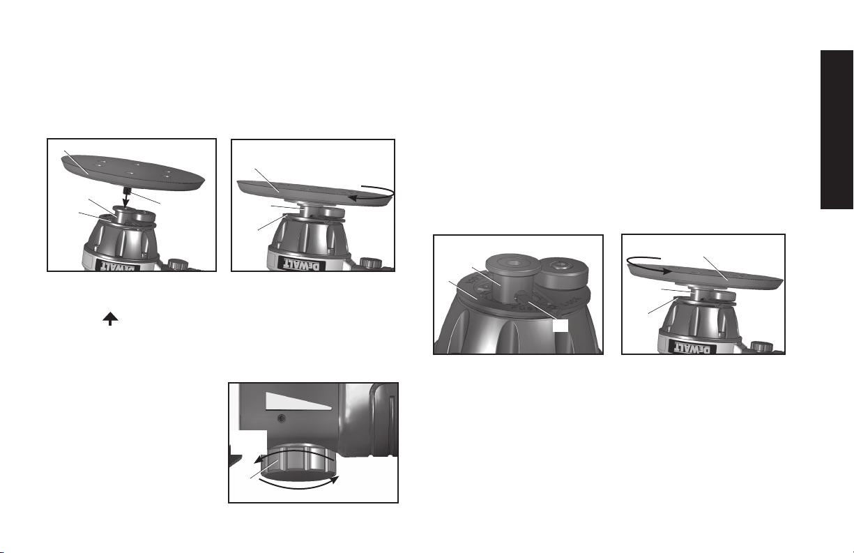
PAD ASSEMBLY CONTINUED
•
Hold the spindle lock (B) and insert the threaded post (J) of
the sanding pad into the drive spindle (C).
•
Tighten the sanding pad (D) by spinning it clockwise until
secure.
•Placedesiredsandpaperontothesanding pad (D).
NOTE: Only use approved self-adhesive type sandpaper.
•Pushthespindle lock (B) on the designated
“PUSH UNLOCK” side so the locking tab (K) is no longer
in the side hole of the drive spindle (C).
IMPORTANT: The tool MUST be in the unlocked position for
orbital action.
The Spindle Lock is for attaching and removing the
sanding pad only. The tool MUST be in the lock position to install
sandpaper pad. Do not operate
the tool with the spindle lock
in the locked position or the
sander will stall when pressure
is applied to the pad.
•
Set the
speed control
dial (E)
to the desired
variable speed.
•Ready for use.
PAD REMOVAL
•
Disconnect the sander from the air supply before removing
the Sanding Pad (D).
•Positionthelocking tab (K) of the spindle lock (B) so that it
lines up with the side hole on the drive spindle (C).
•Pushthespindle lock (B) in order to insert the locking tab (K)
into the drive spindle (C). This will prevent the drive spindle (C)
from rotating.
•Holdthespindle lock (B) and rotate the sanding pad (D)
counterclockwise to unthread the post (J) of the sanding pad
from the drive spindle (C).
•When the
sanding pad (D)
becomes loose enough, it may be
removed from the
drive spindle (C)
.
OPERATING PROCEDURES
Start-up (Fig. 1, pg. 2)
•Connectthetooltoairsourcewiththehoseofrecommendedsize.
•Turnontheaircompressorandallowtheairtanktobefilled.
•Settheaircompressorregulatorto90PSI.Thisair
tooloperatesatamaximumof90PSIairpressure.
•Depressthetriggertostartoperatingthetool.
C
B
D
J
D
B
C
E
Reduce
Speed
Increase
Speed
C
B
K
D
B
C
Loading ...
Loading ...
Loading ...