Loading ...
Loading ...
Loading ...
English
CCD-0005773 Rev: 04-25-22
- 5 -
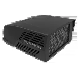
3⁄4" Min.
(19.05 mm)
Leave access for
power supply wiring
Air Distribution Duct Sizing and Design
The installer of this system must design the air distribution
system for their particular application.
NOTE: Make sure ductwork will NOT bend or collapse during
and after installation, and that it is correctly insulated and
sealed. Otherwise, damage to roof structure and ceiling could
occur.
The following requirements must be met for properly operate
the unit:
Roof Cavity Depth 3.5"-6" (89mm-152mm)
Duct Cross
Sectional Area
21 Sq. In. Min.
Duct Size
Depth
1½" Min. - 2½" Max. (38mm
Min. - 63.5mm Max.)
Width
7" Min. - 10" Max. (178mm
Min. - 254mm Max.)
Total Duct Length
15Ft. Min. - 40Ft. Max. (4.5m
- 13m)
Duct Length (short run) 1/3 Total Duct Length
Register
Requirements per
A/C Unit
Number Required 4 Min. - 8 Max.
Supply Register Free
Air Area
14 Sq. In. (90 sq. cm)
Return Register Free
Air Area
40 Sq. In. (258 sq. cm)
Distance From Duct
End
5" Min. - 8" Max. (127mm
Min. - 203mm Max.)
Distance From Elbow 15" (381mm)
Total System Static
Air Pressure
Blower at High Speed,
Filter & Grille In Place
0.55 - 1.10 In. W.C.
● Properly insulate and seal all discharge air ducts to prevent
condensation from forming on their surfaces or adjacent
surfaces during operation of the unit. This insulation must
be R-7 minimum.
Frame
DuctDuct
Frame
Frame
Roof
Opening
Roof Opening
Roof
Duct
Ceiling
Duct
TOP VIEW (BACK OF RV)
SIDE VIEW (TOWARD BACK OF RV)
● Return air openings must have 80 square inches (516
square centimeters) minimum free area including the filter.
● Return air to the unit must be filtered to prevent dirt
accumulation on the unit cooling surface.
Air Distribution System Installation
It is the responsibility of the installer to review each RV floor
plan to determine the following items in conjunction with “Air
Distribution Duct Sizing and Design” section
NOTE: Alternate configurations and methods may be used
which will allow the unit to operate properly, however, these
alternate configurations and methods MUST be approved by
Furrion in writing.
● Duct size
● Duct layout
● Register size
● Register location
● Thermostat location
● Indoor temperature sensor location (if applicable)
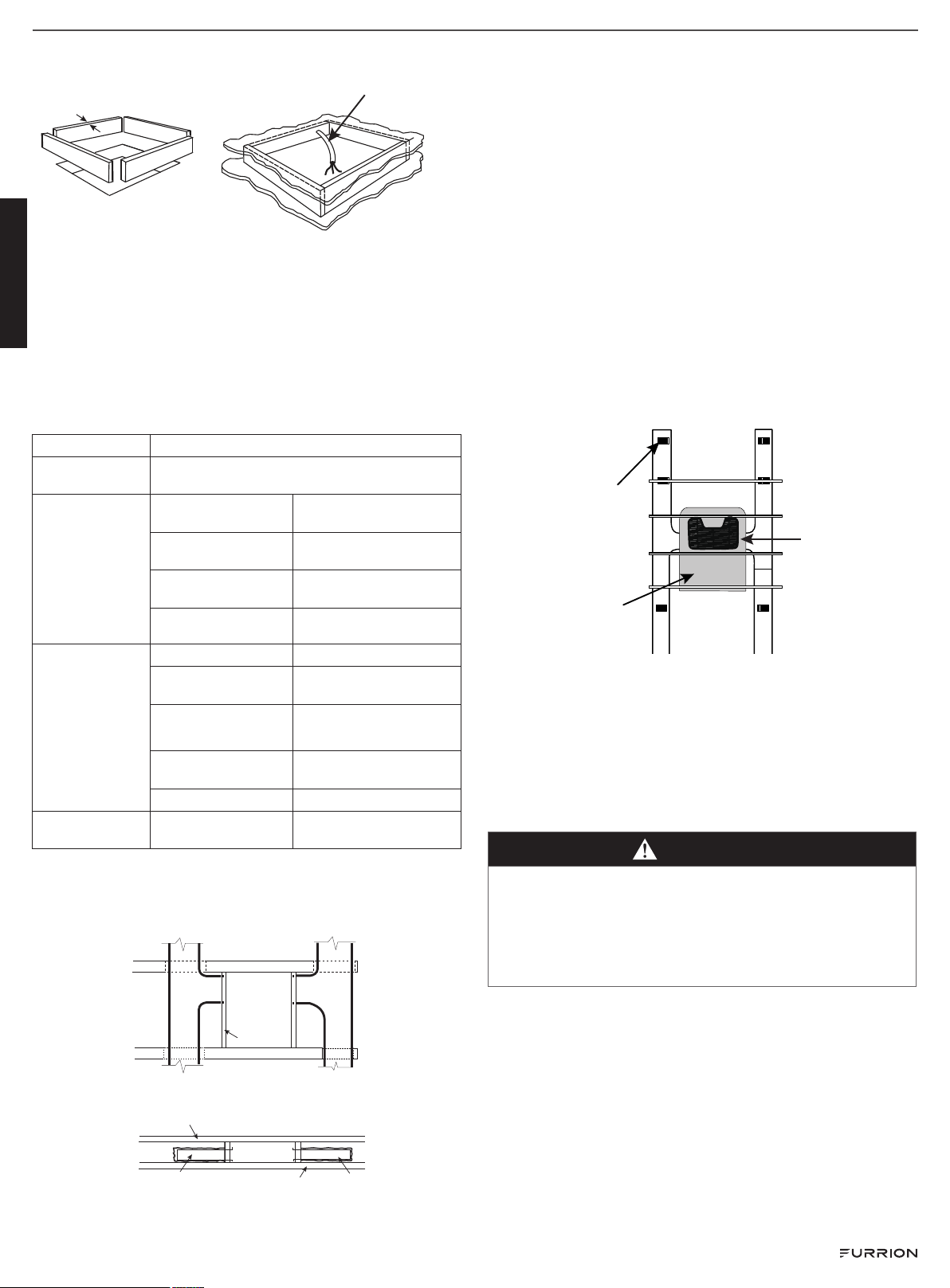
Front
Registers 4
Min - 8 Max.
(Per Unit) 14
Sq. In. Free
Area Per
Register
Air Conditioner
Return Air
Laying the Connecting Cables
The rooftop air conditioner must be connected to an electric
circuit which is able to supply the required power supply (see
chapter “Specification”).
NOTE: The supply wire must be located in the front portion of
the roof opening. The power supply must be equipped with a
time delay fuse or circuit breaker. See rooftop unit nameplate
for rating.
DANGER
Electrical Shock Hazard
● Disconnect power before servicing. Failure to obey this
warning could result in death or serious injury.
● Provide grounding in compliance with all applicable
electrical codes. Failure to obey this warning could result
in death or serious injury.
Refer to the applicable electric code guidelines for sizing the
appropriate wire gauge, length and type.
1. Route a 115VAC supply wire with ground wire from the time
delay fuse or circuit breaker box to the roof opening.
NOTE: Refer to rooftop unit nameplate and applicable
code for proper installation.
2. Use approved method to protect the wire where it passes
through the opening.
3. Feed the 115VAC cable through the opening into the
vehicle interior. Make sure at least 15" (381mm) of supply
wire extends into the roof opening. This ensures an easy
connection at the control box.
Loading ...
Loading ...
Loading ...