Loading ...
Loading ...
Loading ...
NOTE:
When
ENW4X
coils
are
applied
to
same
width
furnace,
remove
block-off
plates
at
casing
base
by
removing
2
screws
per
plate
from
side
of
casing.
See
Figure
3.
Block-Off
A05412
Figure
3
-
Block-Off
Plate
Removal
ENW4X
MODEL
COILS
APPLIED
CENTERED
OVER
NARROW
FURNACE
1.
There
is
no
transition
required
for
this
application.
2.
Remove
coil
from
packaging
and
place
on
top
of
furnace
with
1
5/8
inch
(41
mm)
overhang
on
both
sides.
See
Figure
4,
Alternative
A.
3.
Continue
with
normal
installation
practices.
See
Connect
Refrigerant
Piping.
STANDARD
MODEL
COILS
APPLIED
CENTERED
OVER
NARROW
FURNACE
REQUIRE
A
MINIMUM
TRANSITION
AS
SPECIFIED
IN
Figure
5.
1.
Prepare
transition,
following
recommended
transition
drawing.
See
Figure
5.
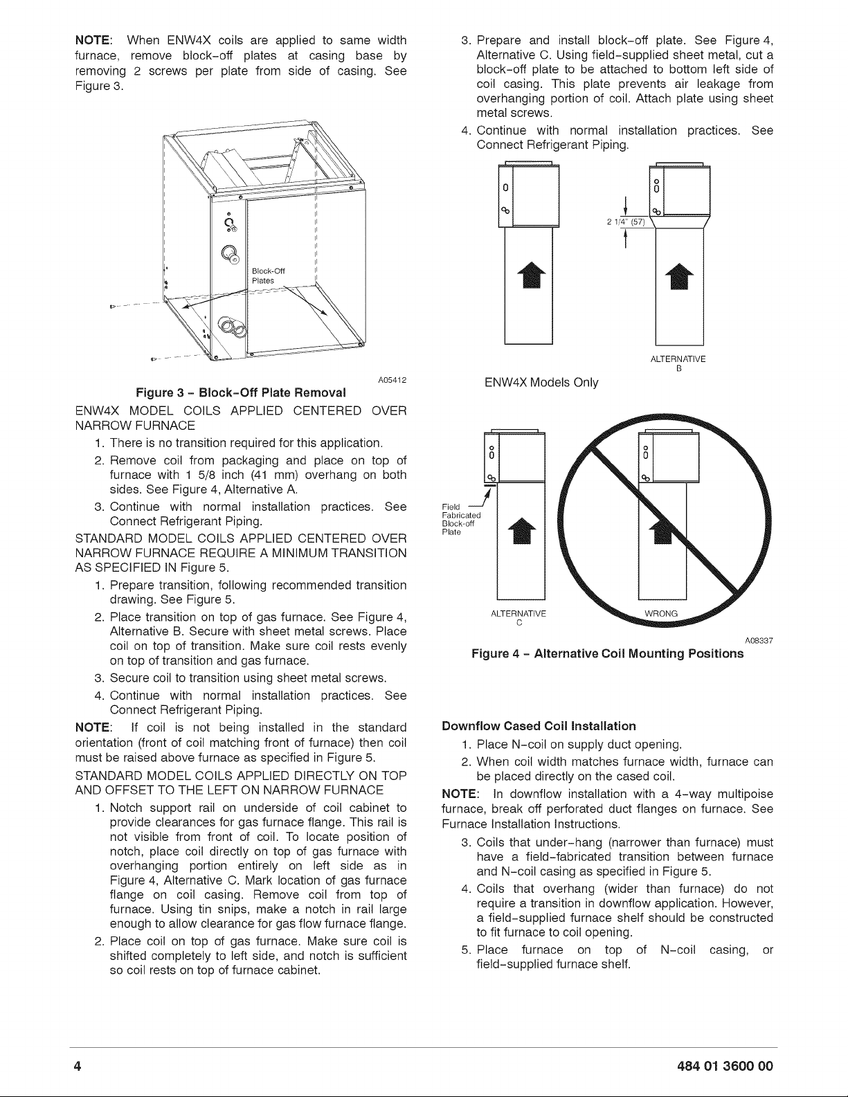
2.
Place
transition
on
top
of
gas
furnace.
See
Figure
4,
Alternative
B.
Secure
with
sheet
metal
screws.
Place
coil
on
top
of
transition.
Make
sure
coil
rests
evenly
on
top
of
transition
and
gas
furnace.
3.
Secure
coil
to
transition
using
sheet
metal
screws.
4.
Continue
with
normal
installation
practices.
See
Connect
Refrigerant
Piping.
NOTE:
[f
coil
is
not
being
installed
in
the
standard
orientation
(front
of
coil
matching
front
of
furnace)
then
coil
must
be
raised
above
furnace
as
specified
in
Figure
5.
STANDARD
MODEL
COILS
APPLIED
DIRECTLY
ON
TOP
AND
OFFSET
TO
THE
LEFT
ON
NARROW
FURNACE
1.
Notch
support
rail
on
underside
of
coil
cabinet
to
provide
clearances
for
gas
furnace
flange.
This
rail
is
not
visible
from
front
of
coil.
To
locate
position
of
notch,
place
coil
directly
on
top
of
gas
furnace
with
overhanging
portion
entirely
on
left
side
as
in
Figure
4,
Alternative
C.
Mark
location
of
gas
furnace
flange
on
coil
casing.
Remove
coil
from
top
of
furnace.
Using
tin
snips,
make
a
notch
in
rail
large
enough
to
allow
clearance
for
gas
flow
furnace
flange.
2.
Place
coil
on
top
of
gas
furnace.
Make
sure
coil
is
shifted
completely
to
left
side,
and
notch
is
sufficient
so
coil
rests
on
top
of
furnace
cabinet.
3.
Prepare
and
install
block-off
plate.
See
Figure
4,
Alternative
C.
Using
field-supplied
sheet
metal,
cut
a
block-off
plate
to
be
attached
to
bottom
left
side
of
coil
casing.
This
plate
prevents
air
leakage
from
overhanging
portion
of
coil.
Attach
plate
using
sheet
metal
screws.
4.
Continue
with
normal
installation
practices.
See
Connect
Refrigerant
Piping.
0 8
®
me
2
1/4”
(57)
@
t
ALTERNATIVE
B
ENW4X
Models
Only
o o
0
0
[%
%
Field
Fabricated
Block-off
Plate
ALTERNATIVE
c
A08337
Figure
4
-
Alternative
Coil
Mounting
Positions
Downflow
Cased
Coil
Installation
1.
Place
N-coil
on
supply
duct
opening.
2.
When
coil
width
matches
furnace
width,
furnace
can
be
placed
directly
on
the
cased
coil.
NOTE:
In
downflow
installation
with
a
4—way
multipoise
furnace,
break
off
perforated
duct
flanges
on
furnace.
See
Furnace
Installation
Instructions.
3.
Coils
that
under-hang
(narrower
than
furnace)
must
have
a
field-fabricated
transition
between
furnace
and
N-coil
casing
as
specified
in
Figure
5.
4.
Coils
that
overhang
(wider than
furnace)
do
not
require
a
transition
in
downflow
application.
However,
a
field-supplied
furnace
shelf
should
be
constructed
to
fit
furnace
to
coil
opening.
5.
Place
furnace
on
top
of
N-coil
casing,
or
field~supplied
furnace
shelf.
484
071
3600
00
Loading ...
Loading ...
Loading ...