Loading ...
Loading ...
Loading ...
8. Install a manual shutoff valve and tighten all joints se-
curely.
9. Make sure pilot tube and burner orifices are checked for
leakage.
ORIFICES
Orifice Sizes
Orifice sizes MUST be matched to the heating value of the
gas (see FIGURE 6 AND TABLE 1). Check with your gas
supplier and the National Fuel Gas Code ANSI Z223.1.
NOTE: An LP Conversion Kit MUST be used for conversion
to LP gas.
NOTE: For elevations above 2000 feet (610 meters), the
Btu input rating MUST be reduced by 4% for each 1000 feet
(305 meters) above sea level, unless the gas supplier's
Btu/ft3 content has already been adjusted for altitude.
Check Table 1 for the proper orifice sizes.
FIGURE6 Orifice Sizes
Gas Specific Btu/ft 3
Type Gravity (kJ/L)
Natural 0.6 1000
Propane 1.53 2500
#Adjust pilot flame as needed
Pilot
Orifice
Sizes
.018#
,012#
TABLE 1: Equivalent Orifice Sizes at High Altitudes
(Includes 4% input reduction for each 1,000 ft.
Natural GasManifoldOrifice Size RequiredbyElevation
BTU 0'- 2000' 4500'
iNPUT 2000' 4000' 5000' 6000' 7000' 8000' 9000' 10000'
40.000 45 46 47 48 48 49 49 50
60,000 45 46 47 48 48 49 49 50
80,000* 41 42 43 43 44 44 45 46
80,000_ 45 46 47 48 48 49 49 50
100,000 42 43 43 44 44 45 46 47
120,000 42 43 43 44 44 45 46 47
140,000 42 43 43 44 44 45 46 47
LPGas ManifoldOrifice Size Required by Elevation
BTUiN- 0'- 2000' 4500'
PUT 2000' 4000' 5000' 6000' 7000' 8000' 9000' 10000'
40.000 56 57 57 57 58 59 59 60
60,000 56 57 57 57 58 59 59 60
80,000* 54 55 55 55 55 56 56 56
80,000_ 56 57 57 57 58 59 59 60
100,000 54 55 55 55 58 56 56 56
120,000 54 55 55 55 55 56 56 56
140,000 54 55 55 55 55 56 56 56
* 2-1/2 & 3 Ton with 3 burners.
** 3-1/2 & 4 ton with 4 burners.
Changing Orifices
Electrical shock, fire and/or explosion hazard.
Shut off electric power at unit disconnect or service panel and
shut off gas at manual shut off valve before beginning the fol-
lowing procedure.
Changing orifices requires a qualified service technician.
Failure to follow this warning can result in property damage,
personal injury, and/or death.
1. Shut OFF gas at manual shut off valve.
2. Shut OFF electric power at unit disconnect or service
panel. If unit is still running, allow 2.5 minutes after gas
shut off before turning off power.
3. Disconnect the wires from the gas valve and discon-
nect pilot tubing from valve.
4. Remove the four screws holding the manifold to the
manifold brackets.
5. Carefully remove the manifold with the gas valve at-
tached.
6. Remove the orifices from the manifold with a 7/16" box
end or socket wrench.
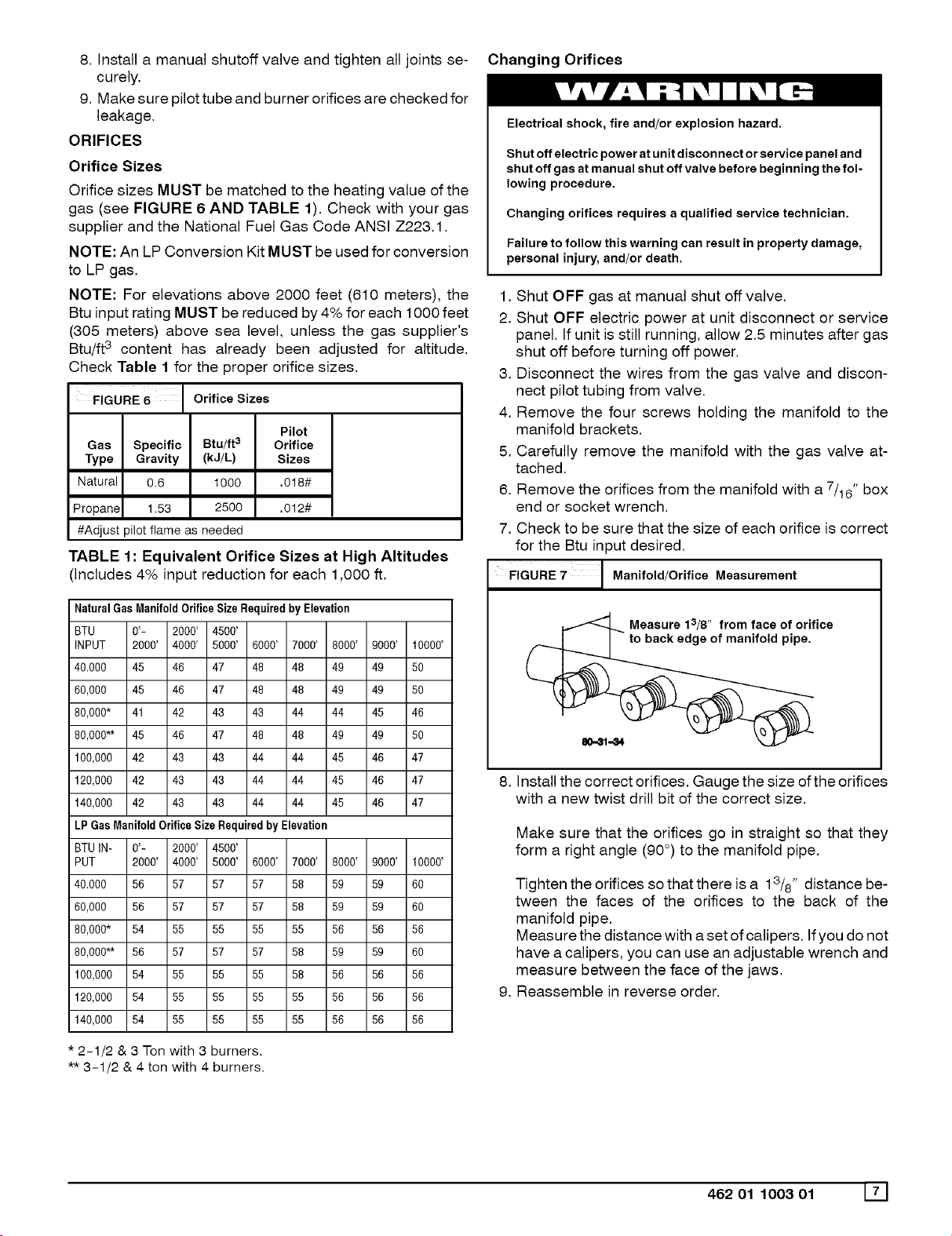
7. Check to be sure that the size of each orifice is correct
for the Btu input desired.
FIGURE Manifold/Orifice Measurement
Measure 13/8" from face of orifice
back edge of manifold pipe.
Install the correct orifices. Gauge the size of the orifices
with a new twist drill bit of the correct size.
Make sure that the orifices go in straight so that they
form a right angle (90°) to the manifold pipe.
Tighten the orifices so that there is a 13/8" distance be-
tween the faces of the orifices to the back of the
manifold pipe.
Measure the distance with a set of calipers. If you do not
have a calipers, you can use an adjustable wrench and
measure between the face of the jaws.
Reassemble in reverse order.
462 01 1003 01 171
Loading ...
Loading ...
Loading ...