
MAAN2213-03
2021-09-08
Installation Instructions
IMPORTANT SAFETY INSTRUCTIONS
Carefully read the important information
regarding installation, safety and maintenance.
Keep these instructions for future reference.
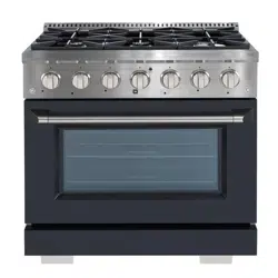
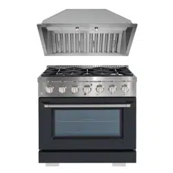
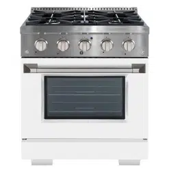
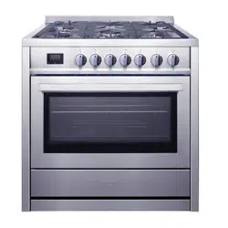
Freestanding Range
Gas Cooktop
and Oven


TABLE OF CONTENTS
RANGE SAFETY ...................................................................................................2
INST
ALLATION REQUIREMENTS
......................................................................... 4
Tools and Parts ............................................................................................................... 4
Location R
equirements
................................................................................................. 6
Electrical Requir
ements
................................................................................................ 9
Gas Suppl
y Requirements
...........................................................................................10
INST
ALLATION INSTRUCTIONS
........................................................................ 13
Step 1 - Unpack R
ange
................................................................................................13
Step 2 - Install Backsplash ...........................................................................................13
Step 3 - Install Anti-tip Bracket ...................................................................................15
Step 4 - Make Gas Connection ....................................................................................17
Step 5 - Make Electrical Connection ...........................................................................19
Step 6 - Install Range ...................................................................................................19
Step 7 - Level the Range (if needed) ..........................................................................21
Step 8 - Check Operation of Electronic Ignition System ...........................................21
GAS CONVERSION ............................................................................................ 22
Step 1 - Adjust the Regulator ......................................................................................25
.................................................................................26
Step 3 - Adjust Burner Flames ....................................................................................27
Step 4 - Testing Flame Stability ...................................................................................28
Step 5 - Flame Re-Check .............................................................................................28
1
RANGE S
AFETY
Your safety and the safety of others are very important.
We have provided many important safety messages in this manual and
on your appliance. Always read and obey all safety messages.
D
ANGER
W
ARNING
CAUTION
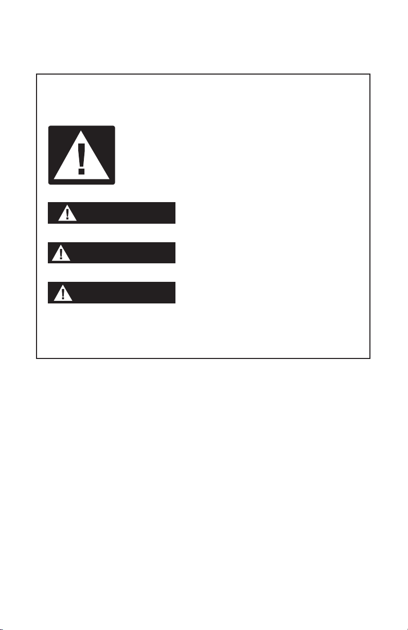
This is the safety alert symbol.
This symbol alerts you to potential hazards that can
kill or hurt you and others. All safety messages will
follow the safety alert symbol and either the word
“DANGER,” “WARNING” or “CAUTION.”
These words mean:
An imminently hazardous situation. You
could be killed or seriously injured if you
don’t immediately follow instructions.
A potentially hazardous situation
which, if not avoided, could result in
death or serious bodily injury.
A potentially hazardous situation
which, if not avoided, may result in
moderate or minor injury.
All safety messages will tell you what the potential hazard is, tell you
how to reduce the chance of injury, and tell you what can happen if the
instructions are not followed.
2
W
ARNING
Fire Hazar
d
If the information in this manual is not followed exactly, a fire or
explosion may result causing property damage, personal injury or
death.
- Do not store or use gasoline or other flammable vapors and liquids in
the vicinity of this or any other appliance.
- WHAT TO DO IF YOU SMELL GAS
• Do not try t
o light any appliance.
•
Do not t
ouch any electrical switch.
•
Do not use an
y phone in your building.
• Clear the r
oom, building, or area of all occupants.
•
Immediatel
y call your gas supplier from a neighbor’s phone. Follow
the gas supplier’s instructions.
• If y
ou cannot reach your gas supplier, call the fire department.
- Installation and service must be performed by a qualified installer,
service agency or the gas supplier.
WARNING: Gas leaks cannot always be detected by smell.
Gas suppliers recommend that you use a gas detector approved by UL
or CSA.
For more information, contact your gas supplier.
If a gas leak is detected, follow the “What to do if you smell gas”
instructions.
In the State of Massachusetts, the following installation instructions
apply:
•
State of Massachusetts.
•
If using a ball valve, it shall be a T-handle type.
•
3
S
tate of California Proposition 65 Warnings:
WARNING: This product contains one or more chemicals known to the
State of California to cause cancer.
WARNING: This product contains one or more chemicals known to the
State of California to cause birth defects or other reproductive harm.
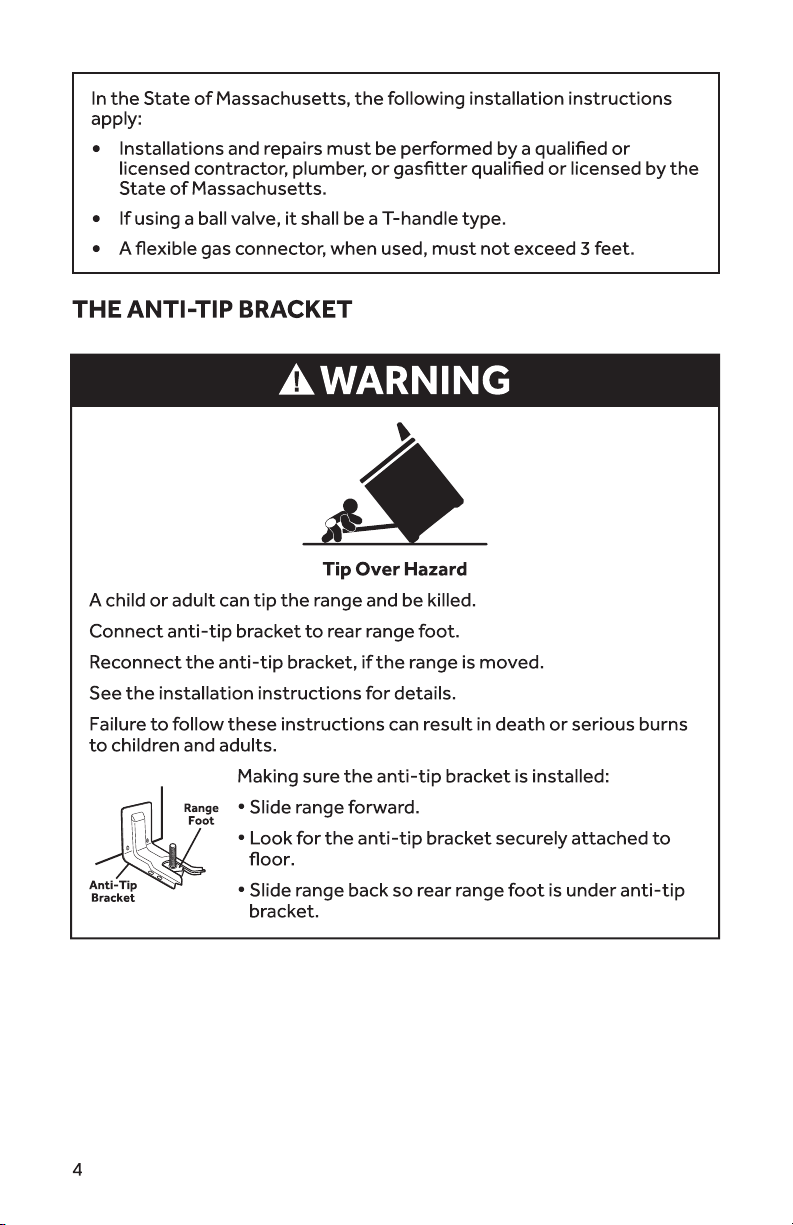
W
ARNING
Tip Over Hazard
A child or adult can tip the range and be killed.
Connect anti-tip bracket to rear range foot.
Reconnect the anti-tip bracket, if the range is moved.
Failure to follow these instructions can result in death or serious burns
to children and adults.
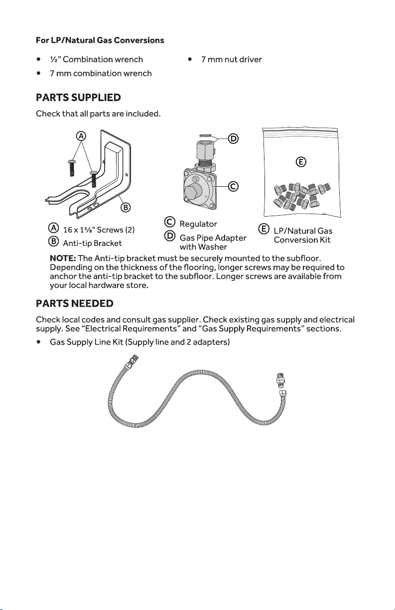
INSTALLATION REQUIREMENTS
T
OOLS AND PARTS
Gather the r
equired tools and parts before starting installation. Read and follow the
instructions provided with any tools listed here.
T
OOLS NEEDED
•
T
ape measure
•
Flat
-blade screwdriver
•
Phillips scr
ewdriver
•
Level
•
C
ordless electric drill
•
Hammer
•
W
rench or pliers
•
Pipe wr
ench
•
10" Adjustable W
renches (2)
•
•
¼" nut driver
•
•
Mark
er or pencil
•
Masking tape
•
Pipe-joint compound resistant to LP gas
•
•
Nonc
orrosive leak-detection solution
4
5
L
OCATION REQUIREMENTS
VENTIL
ATION
IMPOR
TANT:
combustion and ventilation air.
•
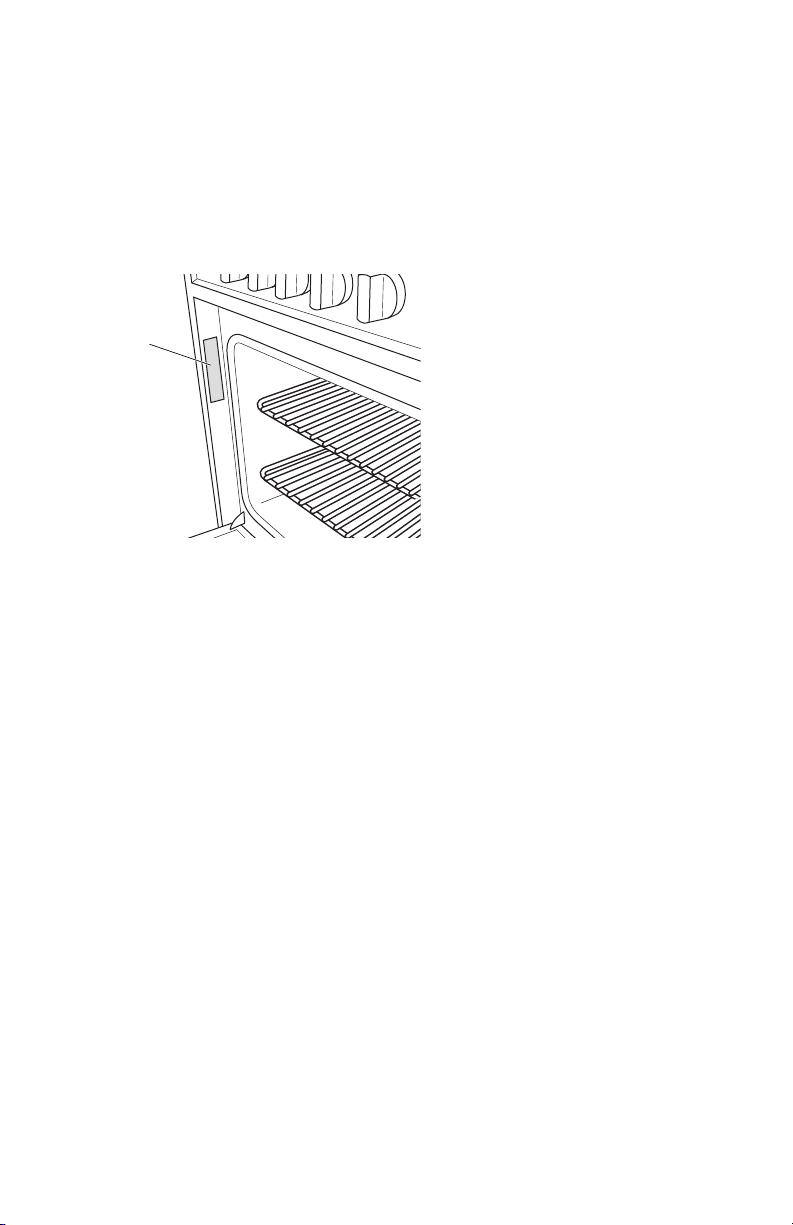
on the model/serial rating plate. The model/serial rating plate is located on the
left-hand side of the oven frame. Open oven door to view label. See label on back
panel of range for additional element and oven power ratings.
a
a R
ating Plate
TEMPERA
TURE
IMPOR
TANT: This oven has been designed in accordance with the requirements of
temperatures of 194F (90°C).
•
S
ome cabinet and building materials are not designed to withstand the heat
produced by the oven for baking and self-cleaning. Check with your builder
or cabinet supplier to make sure that the materials used will not discolor,
delaminate or sustain other damage.
•
withstand at least 200°F (93°C).
•
Use an insulated pad or ¼" (0.64 cm) pl
ywood under range if installing range over
carpeting.
GENERAL
•
T
he range should be located for convenient use in the kitchen.
•
R
ecessed installations must provide complete enclosure of the sides and rear of
the range.
•
cabinet storage space located above the surface units should be avoided. If
cabinet storage is to be provided, the risk can be reduced by installing a range
hood or microwave hood combination that projects horizontally a minimum of 5"
(12.7 cm) beyond the bottom of the cabinets.
•
•
Do no
t seal the range to the side cabinets.
•
Gr
ounded electrical supply is required. See “Electrical Requirements” section.
•
Pr
oper gas supply connection must be available. See “Gas Supply Requirements”
section.
6
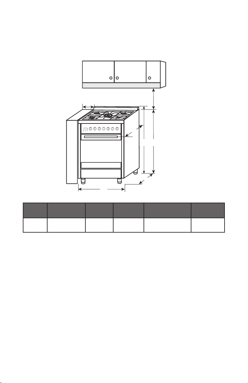
DIMENSIONS
Product and Opening
Opening dimensions shown ar
e for 25" (64.0 cm) countertop depth, 4" (61.0 cm)
base cabinet depth and 36" (91.4 cm) countertop height.
30"
(76 cm)
Min.
5.9"
(15 cm)
Min.
b
d
c
e
a
Model
Size
A. Depth w/
Handle
B. Width C. Depth
D. Height to top
of Cooktop
E. Height
Overall
36"
36" (91 cm)
NOTE:
u
7
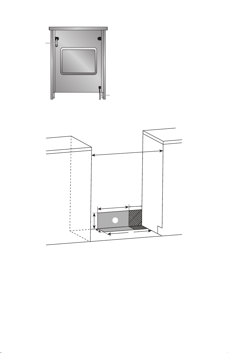
Back of Range
b
a
a Gas Line from R
ange
b Pow
er Cord
Power Supply
IMPORTANT:
mounted, but an electrical outlet in the wall must be recessed to make the
a
b
e
d
g
h
c
f
a
b 11½" (29.2 cm)
c 6" (15.2 cm)
d 7¼" (18.4 cm)
e 3" (7.6 cm)
f 17½" (44 cm)
g Rec
ommended Location for
Electrical Outlet
h Rec
ommended Location for
Gas Supply Connection
*
NOTE:
24" (61.0 cm) minimum when bottom of wood or metal cabinet is covered
No. 28 MSG sheet steel, 0.015" (0.4 mm) stainless steel, 0.024" (0.6 mm) aluminum
or 0.020" (0.5 mm) copper.
30" (76.2 cm) minimum clearance between the cooking and the bottom of an
uncovered wood or metal cabinet.
8
ELE
CTRICAL REQUIREMENTS
WARNING
Electrical Shock Hazar
d
Plug into a grounded 3 prong outlet.
Do not remove the ground prong from the power cord plug.
Do not use an adapter.
Do not use an extension cord.
Failure to do so can result in death, fire or electrical shock.
IMPORTANT: The range must be electrically grounded in accordance with local
codes and ordinances, or in the absence of local codes, with the National Electrical
Code, ANSI/NFPA 70 or Canadian Electrical Code, CSA C22.1.
This range is equipped with an electronic ignition system that will not operate if
plugged into an outlet that is not properly polarized.
If codes permit and a separate ground wire is used, it is recommended that a
A copy of the above code standards can be obtained from:
National Fire Protection Association
1 Batterymarch Park
Quincy, MA 02169-7471
CSA International
8501 East Pleasant Valley Road
Cleveland, OH 44131-5575
•
A 120 volt, 60 Hz., AC onl
y, 15-amp fused, electrical circuit is required. A time-
delay fuse or circuit breaker is also recommended. It is recommended that a
separate circuit serving only this range be provided.
•
Electronic ignition systems operate within wide voltage limits, but proper
grounding and polarity are necessary. Check that the outlet provides 120-volt
power and is correctly grounded.
•
T
his gas range is not required to be plugged into a GFCI (Ground-Fault Circuit
Interrupter) outlet. It is recommended that you not plug an electric spark
ignition gas range or any other major appliance into a GFCI wall outlet as it may
cause the GFCI to trip during normal cycling.
•
circuit. However, occasional nuisance tripping of the GFCI breaker is possible
due to the normal operating nature of electronic gas ranges.
•
T
he wiring diagram is located on the back of the range in a clear plastic bag.
9
NOTE: The metal chassis of the range must be grounded in order for the control
panel to work. If the metal chassis of the range is not grounded, no keypads will
metal chassis of the range is grounded.
G
AS SUPPLY REQUIREMENTS
WARNING
Explosion Hazar
d
Use a new CSA International approved gas supply line.
Install a shut-off valve.
Securely tighten all gas connections.
If connected to LP, have a qualified person make sure gas pressure
does not exceed 14" (36 cm) water column.
Examples of a qualified person include:
licensed heating personnel,
authorized gas company personnel, and
authorized service personnel.
Failure to do so can result in death, explosion or fire.
Observe all governing c
odes and ordinances.
IMPORTANT: This installation must conform with all local codes and ordinances.
In the absence of local codes, installation must conform with American National
Standard, National Fuel Gas Code ANSI Z223.1 - latest edition or CAN/CGA B149 –
latest edition.
IMPORTANT: Leak testing of the range must be conducted according to the
manufacturers instructions.
TYPE OF G
AS
Nat
ural gas:
proper conversion, for use with LP gas.
•
T
his range is factory set for use with Natural gas. See “Gas Conversions”
section. The model/serial rating plate located on the right side oven door trim
has information on the types of gas that can be used. If the types of gas listed do
not include the type of gas available, check with the local gas supplier.
10
LP gas conversion:
IMPORTANT:
gas supplier. See “Gas Conversions” section.
G
AS SUPPLY LINE
Provide a gas supply line of ¾" (1.9 cm) rigid pipe to the range location. A smaller size
resist the action of LP gas must be used. With LP gas, piping or tubing size can be ½"
(1.3 cm) minimum. Usually, LP gas suppliers determine the size and materials used in
the system.
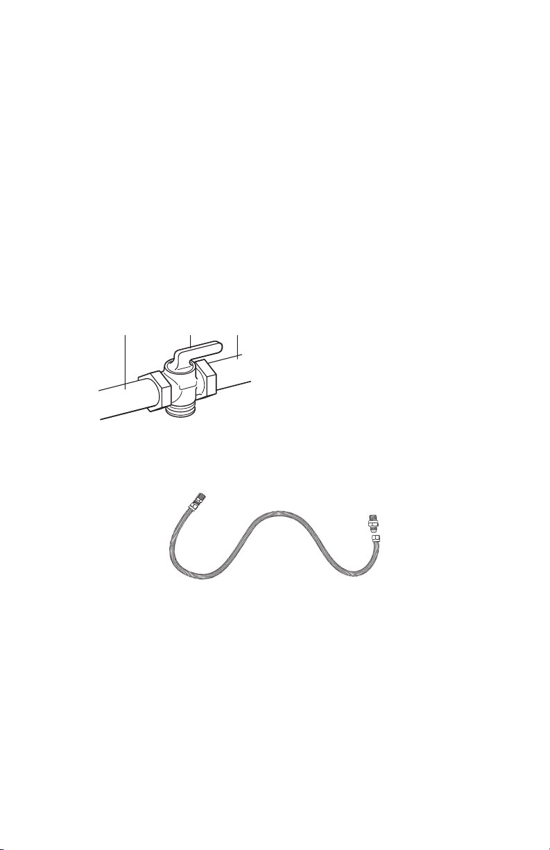
Gas Shut-o Valve:
•
a b c
a Gas S
upply Line
b
c
Flexible metal appliance connector:
•
for connecting range to the gas supply line.
•
A ½" (1.3 cm) male pipe thr
ead is needed for connection to the female pipe
threads of the inlet to the appliance pressure regulator.
•
11
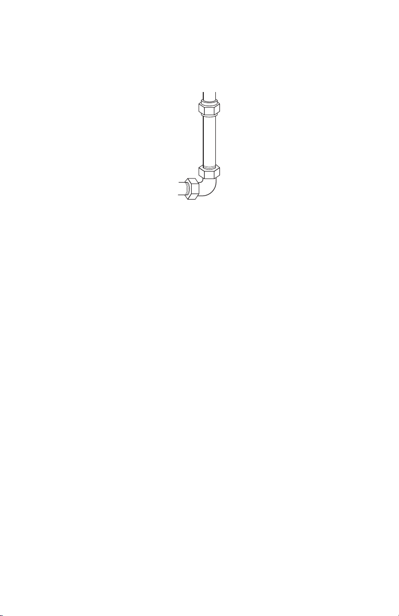
Rigid pipe connection:
connection to the range. The rigid pipe must be level with the range connection. All
strains must be removed from the supply and fuel lines so range will be level and in
line.
G
AS PRESSURE REGULATOR
T
he gas pressure regulator supplied with this range must be used. The inlet pressure
to the regulator should be as follows for proper operation:
Natural gas:
Minimum pressure: 5" Water Column Pressure (WCP)
LP gas:
Minimum pressure: 8" WCP
Contact local gas supplier if you are not sure about the inlet pressure.
Burner Input Requirements
Input ratings shown on the model/serial rating plate are for elevations up to 2,000 ft
(609.6 m).
For elevations above 2,000 ft (609.6 m), ratings are reduced at a rate of 4% for each
1,000 ft (304.8 m) above sea level (not applicable for Canada).
G
AS SUPPLY PRESSURE TESTING
Gas suppl
y pressure for testing regulator must be at least 1" Water Column Pressure
(WCP) above the manifold pressure shown on the model/serial rating plate.
Line pressure testing above 0.5 psi gauge (14" WCP)
of 0.5 psi (3.5 kPa).
Line pressure testing at 0.5 psi gauge (14" WCP) or lower
The range must be isolated from the gas supply piping system by closing its
system at test pressures equal to or less than 0.5 psi (3.5 kPa).
12

INSTALLATION INSTRUCTIONS
IMPORT
ANT: This appliance shall be installed only by authorized persons and
regulations, municipal building codes, electrical wiring regulations, local water
supply regulations.
STEP 1 - UNPA
CK RANGE
WARNING
Excessive W
eight Hazard
Use two or more people to move and install range.
Failure to do so can result in back or other injury.
1.
bottom under range. Do not dispose of anything until the installation is
complete.
2.
Remove oven r
acks and parts package from oven and shipping materials.
3.
Stack one cardboard corner on top of another. Repeat with the other 2 corners.
it is laid on its back.
4.
the cardboard corners.
5.
Remove cardboard bottom.
NOTES:
•
The leveling legs can be adjusted while the range is on its back.
•
To place range back up into a standing position, put a sheet of cardboard or
more people, stand range back up onto the cardboard or hardboard.
S
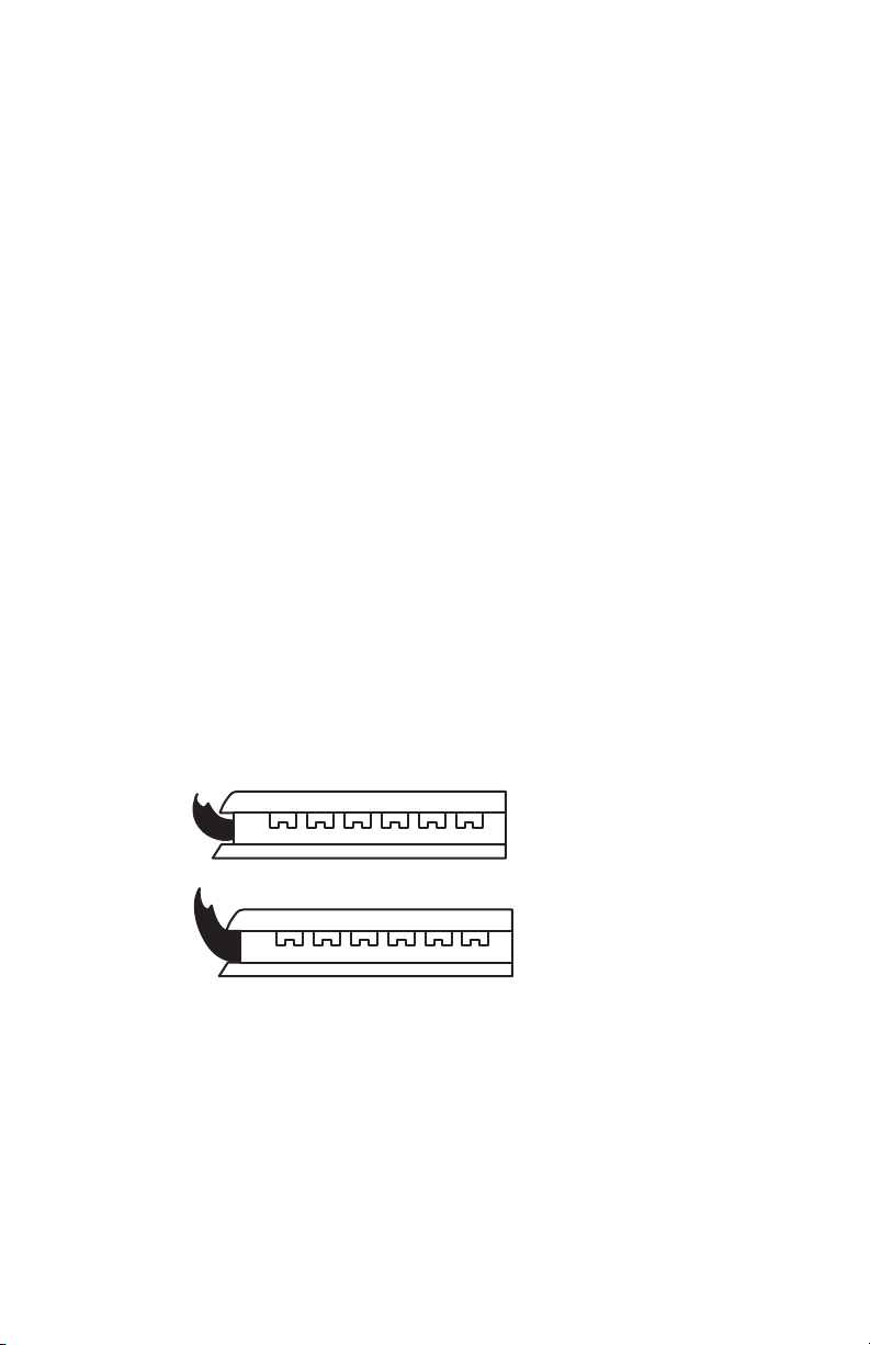
TEP 2 - INSTALL BACKSPLASH
For proper ventilation and to protect your wall from splatters, install the backsplash
Parts Provided: Screws (6)
NOTE: 36" model uses (6) screws
1.
Align the holes in the backsplash with the holes in the back edge of the cookt
op.
2.
With one person holding the backsplash, and w
orking from underneath the
the bottom of the backsplash. Tighten completely.
13
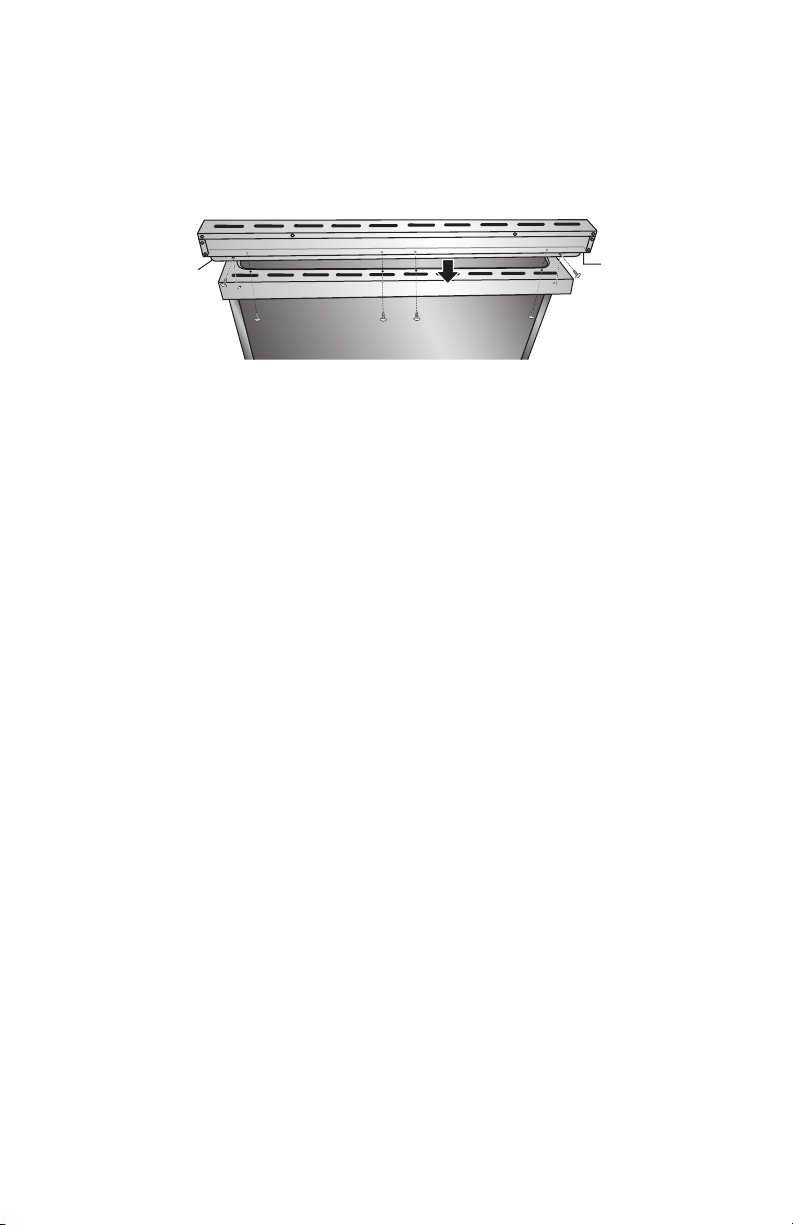
36" Model
a
b
a
Backsplash -Back Edge
b Backsplash - Bottom Edge
3.
Insert the two screws (one on each side) through the back edge of the
backsplash and into the cooktop. Tighten completely.
14
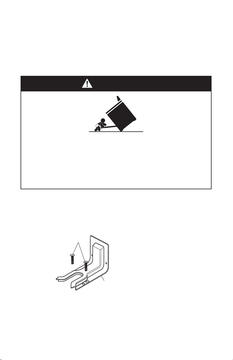
STEP 3 - INSTALL ANTI-TIP BRACKET
IMPORTANT: This insert replaces the directions for “Installing the
Anti-Tip Bracket” and “Installing the Range”.
INSTALL ANTI-TIP BRACKET
WARNING
Tip Over Hazard
A child or adult can tip the range and be killed.
C
onnect anti-tip bracket to rear range foot.
Reconnect the anti-tip bracket, if the range is moved.
Failure to follow these instructions can result in death or serious burns
to children and adults.
IMPORTANT
:
•
An anti-tip bracket is pr
ovided with the range. The anti-tip bracket uses a rear
•
1. Remove the anti-tip bracket and two screws (provided) from the parts bag.
a
b
a
b Anti-tip Bracket
NO
TE:
2.
NOTE:
15
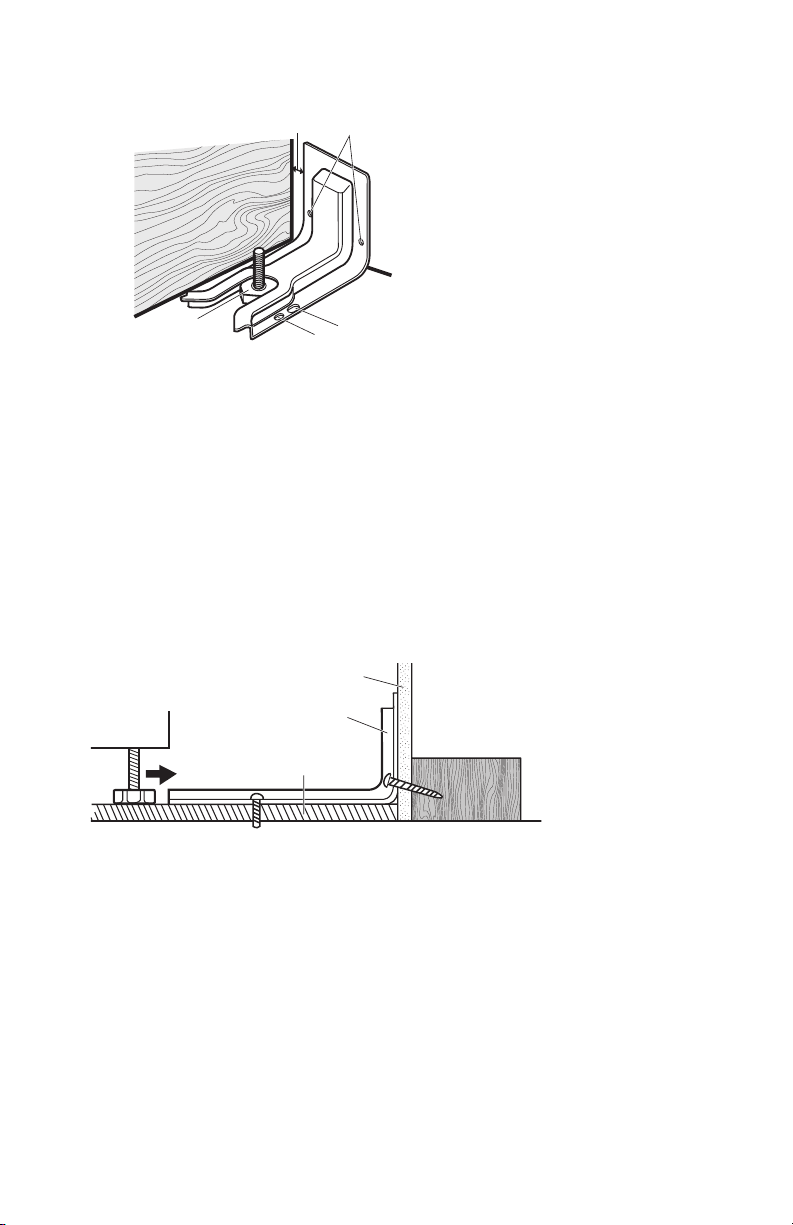
3.
a
b
c
d
e
a Distance from
b
c
d
e
4.
construction.
NOTE:
Wood
•
NOTE:
•
Concrete
•
a
b
c
a
b Anti-tip
Brack
et
c
5.
Wood
•
NOTE:
Concrete
•
6.
(provided).
16
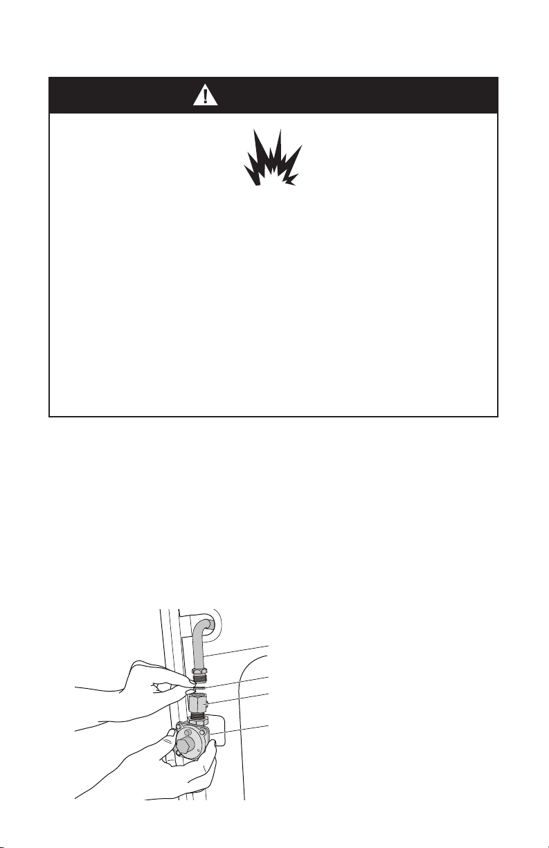
STEP 4 - MAKE G
AS CONNECTION
WARNING
Explosion Hazard
Use a ne
w CSA International approved gas supply line.
Install a shut-off valve.
Securely tighten all gas connections.
If connected to LP, have a qualified person make sure gas pressure
does not exceed 14" (36 cm) water column.
Examples of a qualified person include:
licensed heating personnel,
authorized gas company personnel, and
authorized service personnel.
Failure to do so can result in death, explosion or fire.
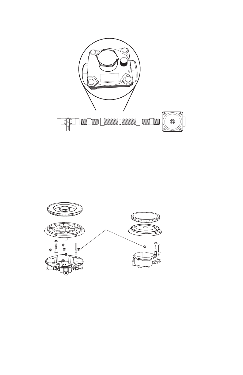
TYPICAL FLEXIBLE C
ONNECTION
CONNE
CT BSPP TO NPT ADAPTER TO GAS REGULATOR:
1.
Apply pipe-joint c
ompound made for use with LP gas to the male threads of
adapter
c
.
2. Insert adapter
c
into outlet of the gas pr
essure regulator
d
, and then tighten
up toward the range gas inlet pipe.
3.
Install washer
b
in female end of adapter
c
, and then connect adapter
c
to
r
ange gas inlet pipe
a
NOTE: Washer
b
must be used to cr
eate a leak proof seal.
a
b
c
d
a Gas Line from R
ange
b Washer (provided)
c Adapter (pr
ovided)
d Gas Pressure Regulator
(provided)
17
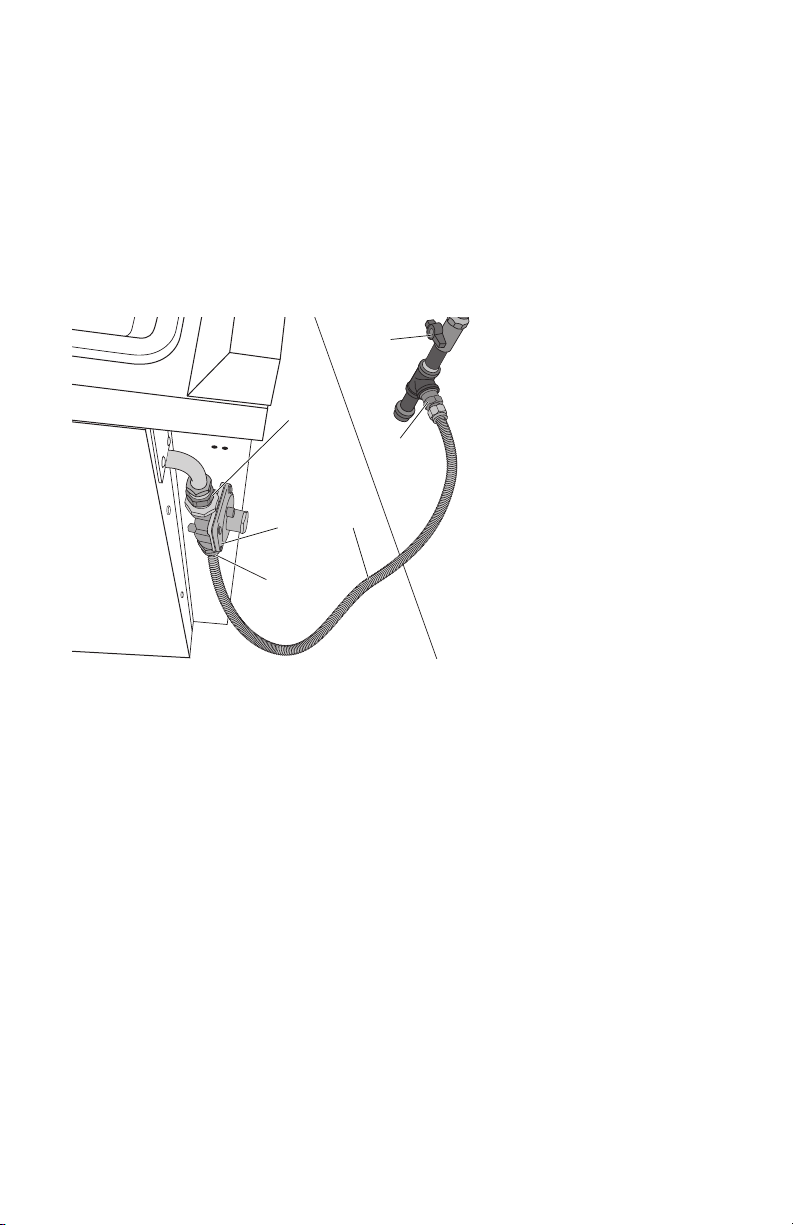
CONNECT GAS LINE FROM GAS PRESSURE REGULATOR TO GAS SUPPLY:
1. Apply pipe-joint compound made for use with LP gas to the tapered (NPT)
threads of both adapters
d
supplied with gas line kit.
2. Attach one adapter to the gas pressure regulator and the other to the gas
NOTE: Do Not rotate the gas pressure regulator.
3.
c
to adapter
s
d
, one adapter at each end.
IMPORT
ANT: All connections must be wrench tightened (requires two 10"
adjustable wrenches). Do not over-tighten the connections to the gas pressure
regulator. Overtightening may crack the regulator creating a leak.
b
c
e
a
d
d
a
Adapter (provided)
b Gas Pressur
e Regulator
c Gas Suppl
y Line
d Adapters (Fr
om Gas
Supply Line Kit)
e
COMPLETE C
ONNECTION
1.
handle is parallel to the gas pipe.
2.
Test all c
onnections by brushing on an approved noncorrosive leak-detection
solution. If bubbles appear, a leak is indicated. Correct any leak found.
18
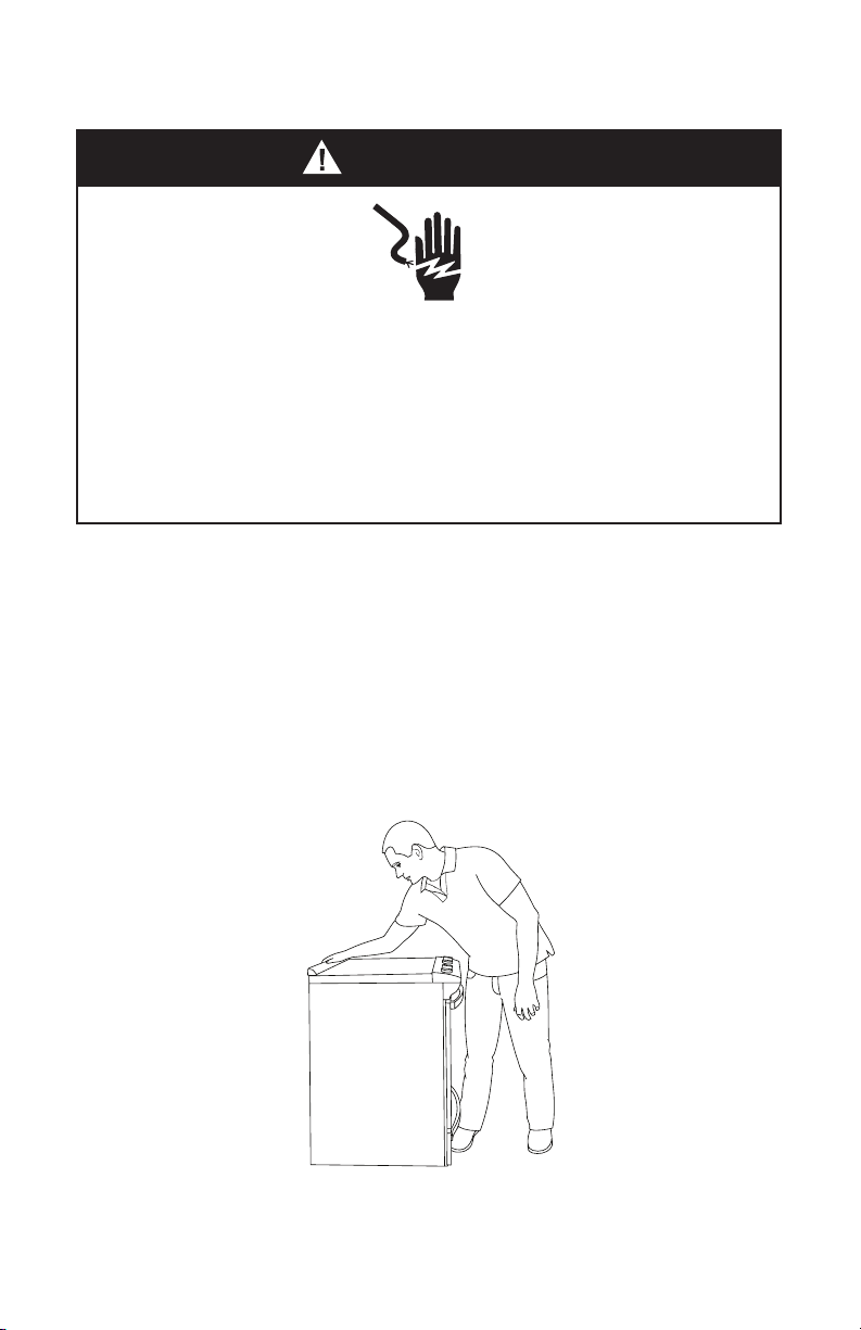
S
TEP 5 - MAKE ELECTRICAL CONNECTION
W
ARNING
Electrical Shock Hazar
d
Plug into a grounded 3 prong outlet.
Do not remove the ground prong from the power cord plug.
Do not use an adapter.
Do not use an extension cord.
Failure to do so can result in death, fire or electrical shock.
1.
2.
Plug int
o a grounded 3 prong outlet.
S
TEP 6 - INSTALL RANGE
IMPOR
TANT: If the range is moved to adjust the leveling legs, make sure when you
repeating steps 1 through 8.
1.
bracket. Leave a 1" (2.5 cm) gap between the back of the range and the back wall.
2.
Place the outside of y
our foot against the bottom front to keep the range from
moving, and then grasp the back of the range, as shown.
19

3. Slowly attempt to tilt the range forward.
If you encounter immediate resistance, the range foot is engaged in the anti-tip
bracket. Go to Step 8.
4.
foot is not engaged in the anti-tip bracket.
IMPORTANT: If there is a snapping or popping sound when lifting the range,
the range may not be fully engaged in the bracket. Check to see if there are
obstructions keeping the range from sliding to the wall or keeping the range foot
from sliding into the bracket. Verify that the bracket is held securely in place by
the mounting screws.
5. Slide the range forward, and verify that the anti-tip bracket is securely attached
6. Slide range back so the rear range foot is inserted into the slot of the anti-tip
bracket.
7. Repeat steps 1 and 2 to ensure that the range foot is engaged in the anti-tip
bracket.
resistance, the anti-tip bracket may not be installed correctly. Do not operate
the range without anti-tip bracket installed and engaged.
8.
to check that the range is level from side to side and front to back.
NOTE: The range must be level for optimum cooking and baking performance.
9. If needed, use a wrench to adjust the height of the leveling legs until the range is
level from side to side.
S
TEP 7 - LEVEL THE RANGE (IF NEEDED)
IMPOR
TANT: The range must be level.
1.
If the r
ange is not level, pull the range forward until rear leveling leg is disengaged
from the anti-tip bracket.
2.
3.
Place the level on the r
ack.
4.
Using a wr
ench or pliers, adjust the leveling legs up or down until the range is
level.
5.
Push r
ange back into position. Check that rear leveling leg is engaged in the
anti
-tip br
acket.
20
S
TEP 8 - CHECK OPERATION OF ELECTRONIC
IGNITION SYSTEM
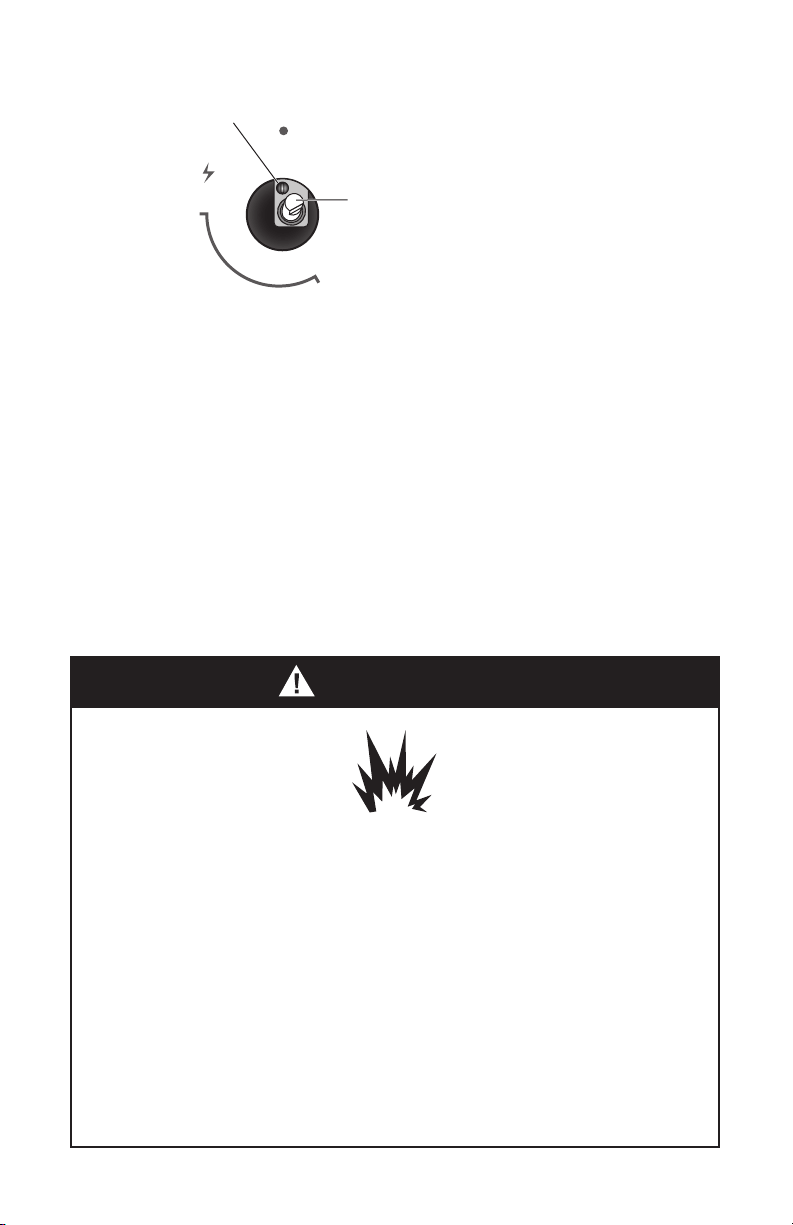
The cooktop and oven burners use electronic igniters in place of standing pilots.
When the cooktop control knob is turned to the “ICON” position, the system
creates a spark to light the burner.
This sparking continues, as long as the control knob is turned to “ICON.”
When the oven control is turned to the desired setting, sparking occurs and ignites
the gas.
Check Operation of Standard Surface Burners:
light because of air in the gas line.
If burners do not light properly:
1. Turn burner control knob to the “OFF” position.
2. Check that the range is plugged in. Check that the circuit breaker has not tripped
or the household fuse has not blown.
3.
4. Check that burner caps are properly positioned on burner bases.
Repeat start-up. If a burner does not light at this point, turn the control knobs to
the “OFF” position and contact your dealer or authorized service company for
assistance.
To adjust ame height:
a
b
a
L
ow Flame
b
High Flame
T
o adjust standard burner:
IMPORTANT: Adjustments must be made with two other burners in operation on
stem. The valve stem is located directly behind the control knob.
21
If the low ame needs to be adjusted:
MA
X
MIN
OFF
a
b
a Adjustment Scre
w
b Contr
ol Knob Stem
1.
Light one burner and turn the c
ontrol knob to the lowest setting.
2.
Remove the c
ontrol knob.
3.
•
•
4.
Replace the c
ontrol knob.
5.
each setting.
6. Repeat above steps for each burner.
GAS CONVERSION
WARNING
Explosion Hazard
Use a ne
w CSA International approved gas supply line.
Install a shut-off valve.
Securely tighten all gas connections.
If connected to LP, have a qualified person make sure gas pressure
does not exceed 14" (36 cm) water column.
Examples of a qualified person include:
licensed heating personnel,
authorized gas company personnel, and
authorized service personnel.
Failure to do so can result in death, explosion or fire.
22
LP/PROPANE GAS C
ONVERSION
This appliance can be used with Natur
al Gas or LP/Propane gas. It is shipped from
the factory for use with natural gas. A kit for converting to LP gas is supplied with
your cooktop. The kit is marked “FOR LP/PROPANE GAS CONVERSION”.
When the cooktop is converted for liquid petroleum (LP) gas, the LP gas supply is
cooktop regulator.
with the kit instructions and all local codes and requirements. Failure to follow
performing this work assumes responsibility for the conversion.
23
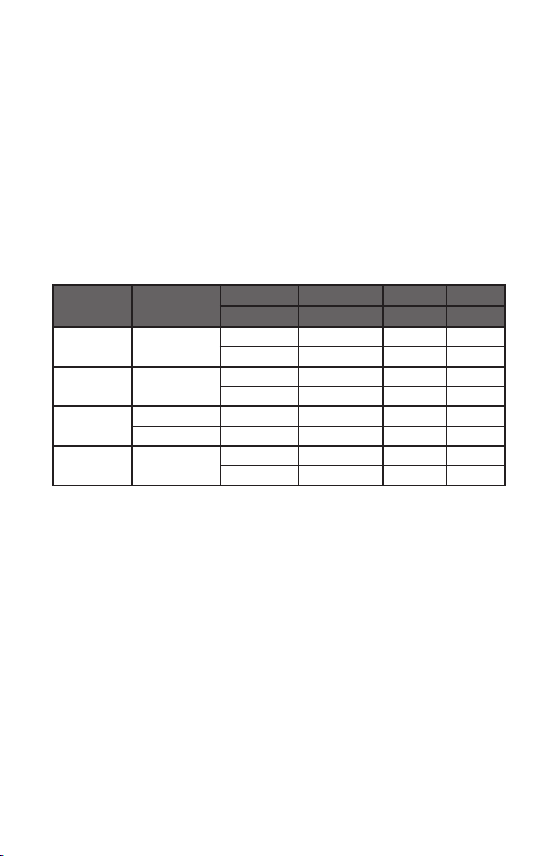
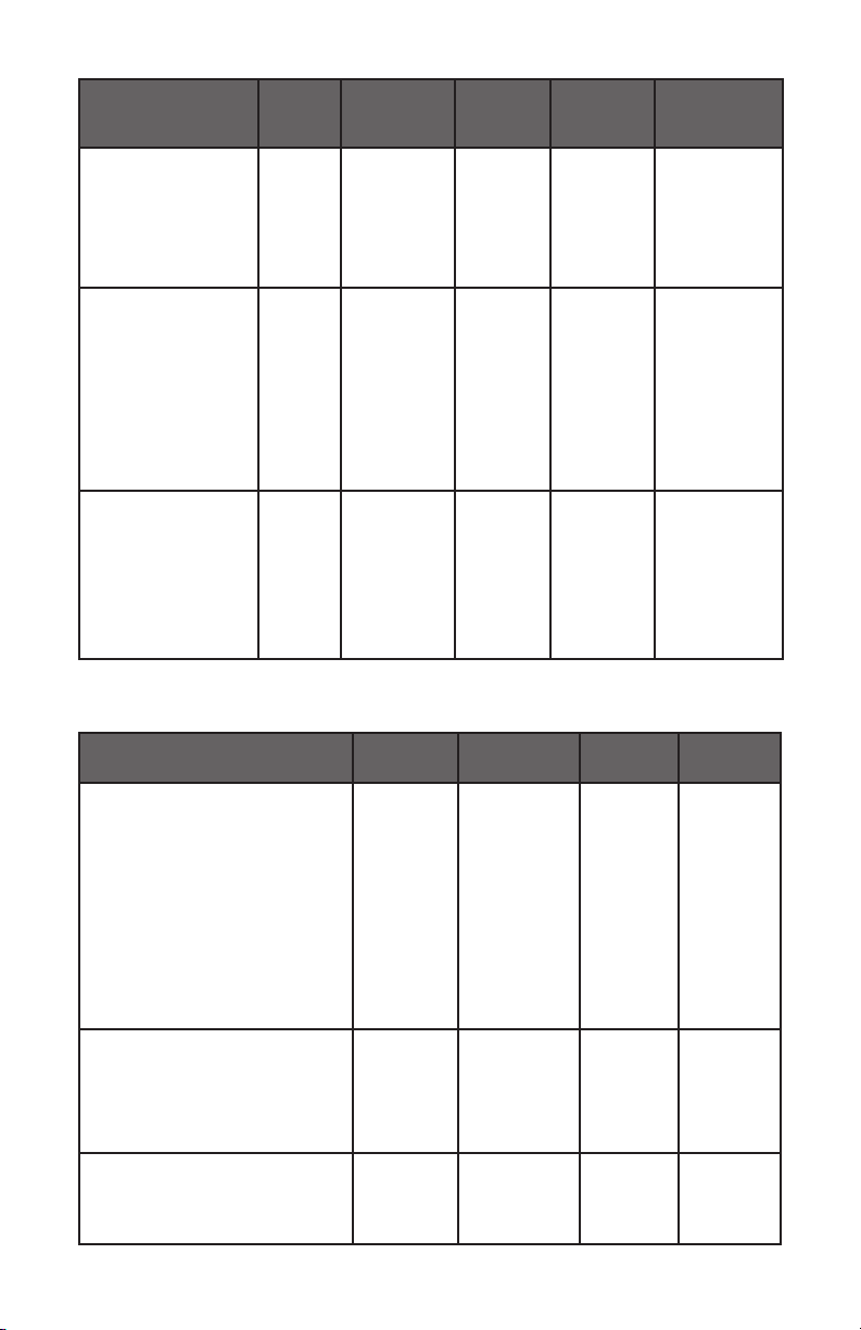
36" Burner and Orice Characteristic Table
Burner Position
Orice Gas Pressure Rate
Diam. (mm) Type [i.w.c.] [BTU/h]
Front R 1.1 NG 4" 5000
0.7 LP (Propane) 10" 5000
Semi-Rapid Rear L and R 1.29 NG 4" 6900
0.8 LP (Propane) 10" 6500
Dual Burner Middle Inner
0.99 x 5
NG 4"
17400
Middle Outer
0.56 x 5
LP (Propane) 10" 15000
Rapid
Burner
Front L 1.45 NG 4"
8200
0.91 LP (Propane) 10"
8300
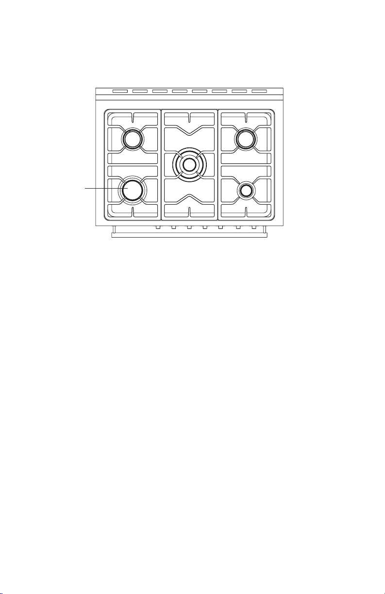
a
a Opening in grate for wok ring (provided) is located over left front burner.
Tools Needed for Conversion:
•
Wrench
•
7 mm Nut Driver
•
Safety Glasses
•
Small Flat-head Screwdriver
24
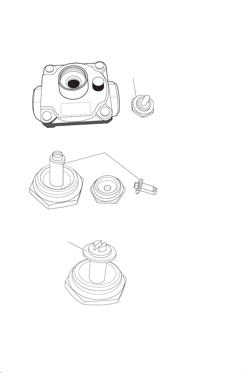
STEP 1 - AD
JUST THE REGULATOR
IMPORT
ANT:
1.
Unscre
w the regulator cap with the wrench.
a
a Regulat
or Cap
2.
Remove the r
etainer pin that is currently positioned for use with Natural Gas.
a
a Retainer Pin
3. Turn the r
etainer pin upside down and replace it into the regulator cap. It is now
positioned for use with LP gas.
a
a R
etainer Pin
25
4. Screw the regulator cap back into the regulator and reattach the regulator to the
S
TEP 2 - CHANGE BURNER ORIFICES
IMPOR
TANT:
the Burner Chart earlier in this section.
NOTE:
possibility that some may not be replaced.
1.
R
emove the burner grates, burner caps and burner heads.
2.
a
a
T
riple Ring Burner
5
Semi-Rapid Burner
Rapid Burner
1 Each
3.
4. Replace the burner bases, heads, caps and top grates. Make sure burner caps are
properly seated on the burner head.
26
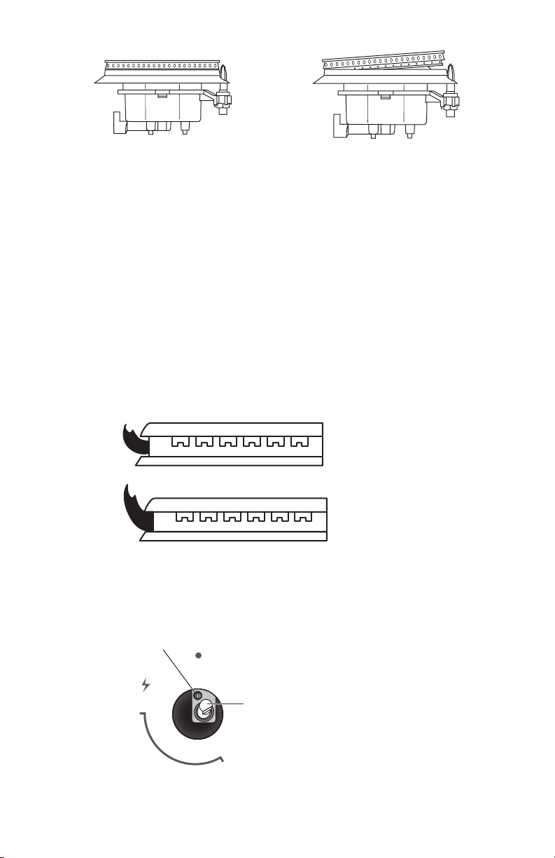
Pr
operl
y Seated Not Properly Seated
STEP 3 - AD
JUST BURNER FLAMES
NOTE
S:
•
will soon disappear.
•
•
Adjustments must be made with tw
o other burners in operation on a medium
To adjust ame height:
a
b
a Lo
w Flame
b High Flame
To adjus
t standard burner:
stem. The valve stem is located directly behind the control knob.
If the low ame needs to be adjusted:
MA
X
MIN
OFF
a
b
a Adjustment Scre
w
b Contr
ol Knob Stem
1.
Light one burner and turn the c
ontrol knob to the lowest setting.
27

2. Remove the control knob.
3.
•
•
4.
Replace the c
ontrol knob.
5.
each setting.
6. Repeat above steps for each burner.
S
TEP 4 - TE
STING FLAME STABILITY
Tes
t 1
Test 2 - With the burner on “LO”, open and close the cabinet door under the
S
TEP 5 - FL
AME RE-CHECK
IMPORTANT: Once the conversion has been completed and has passed testing,
conversion is made. Apply the sticker near the cooktop gas inlet opening to alert
others in the future that this appliance has been converted. If converting back to
Natural Gas, please remove the sticker so others know that the appliance is set to
use its original gas.
ABNORMAL OPERATION
ANY OF THE FOLLO
WING ARE CONSIDERED TO BE ABNORMAL OPERATION
AND MAY REQUIRE SERVICING:
•
•
Soo
ting up of cooking utensils.
•
Burners no
t igniting properly.
•
Burners failing to remain lit.
•
•
IN CASE THE APPLIANCE FAILS TO OPERATE CORRECTLY, CONTACT THE
AUTHORIZED SERVICE PROVIDER IN YOUR AREA
THE BURNERS REQUIRE NO REGULATION OF THE PRIMARY AIR
28

Freestanding Range
Gas Cooktop
and Oven
MAAN2213-03
2021-09-08
User Manual
IMPORTANT SAFETY INSTRUCTIONS
Carefully read the important information
regarding installation, safety and maintenance.
Keep these instructions for future reference.


1
TABLE OF CONTENTS
RANGE SAFETY ...................................................................................................2
The Anti-tip Bracket ...................................................................................................... 4
PARTS AND FEATURES ....................................................................................... 8
ELECTRONIC CONTROL ................................................................................... 10
Setting the Clock and Timer .......................................................................................10
COOKTOP USE .................................................................................................. 12
Ignition and Operation of the Burners ........................................................................ 12
Cookware .....................................................................................................................13
OVEN USE ......................................................................................................... 14
Cooking with the Gas Oven ........................................................................................14
Oven Tips and Techniques ..........................................................................................15
RANGE CARE .................................................................................................... 18
Cleaning .......................................................................................................................18
TROUBLESHOOTING ........................................................................................ 20
Baking and Roasting Problems ....................................................................................20
Cooktop
.......................................................................................................................21
Oven
............................................................................................................................. 22
2
RANGE SAFETY
Your safety and the safety of others are very important.
We have provided many important safety messages in this manual and
on your appliance. Always read and obey all safety messages.
DANGER
WARNING
CAUTION
This is the safety alert symbol.
This symbol alerts you to potential hazards that can
kill or hurt you and others. All safety messages will
follow the safety alert symbol and either the word
“DANGER,” “WARNING” or “CAUTION.”
These words mean:
An imminently hazardous situation. You
could be killed or seriously injured if you
don’t immediately follow instructions.
A potentially hazardous situation
which, if not avoided, could result in
death or serious bodily injury.
A potentially hazardous situation
which, if not avoided, may result in
moderate or minor injury.
All safety messages will tell you what the potential hazard is, tell you
how to reduce the chance of injury, and tell you what can happen if the
instructions are not followed.
3
WARNING
Fire Hazard
If the information in this manual is not followed exactly, a fire or
explosion may result causing property damage, personal injury or
death.
- Do not store or use gasoline or other flammable vapors and liquids in
the vicinity of this or any other appliance.
- WHAT TO DO IF YOU SMELL GAS
• Do not try to light any appliance.
• Do not touch any electrical switch.
• Do not use any phone in your building.
• Clear the room, building, or area of all occupants.
• Immediately call your gas supplier from a neighbor’s phone. Follow
the gas supplier’s instructions.
• If you cannot reach your gas supplier, call the fire department.
- Installation and service must be performed by a qualified installer,
service agency or the gas supplier.
State of California Proposition 65 Warnings:
WARNING: This product contains one or more chemicals known to the
State of California to cause cancer.
WARNING: This product contains one or more chemicals known to the
State of California to cause birth defects or other reproductive harm.

5
IMPORTANT SAFETY
INSTRUCTIONS
WARNING:
or damage when using the range, follow basic precautions, including
the following:
•
WARNING: TO REDUCE
THE RISK OF TIPPING OF
THE RANGE, THE RANGE
MUST BE SECURED BY
PROPERLY INSTALLED
ANTI-TIP DEVICES. TO
CHECK IF THE DEVICES
ARE INSTALLED PROPERLY,
SLIDE RANGE COMPLETELY
FORWARD, LOOK FOR ANTI-
TIP BRACKET SECURELY
ATTACHED TO THE FLOOR
BEHIND THE RANGE AND
SLIDE RANGE COMPLETELY
BACK UNTIL THE REAR
RANGE FOOT IS UNDER
ANTI-TIP BRACKET.
•
WARNING: NEVER use this
appliance as a space heater
to heat or warm the room.
Doing so may result in carbon
overheating of the oven.
•
WARNING: NEVER cover
any slots, holes or passages
in the oven bottom or cover
an entire rack with materials
such as aluminum foil. Doing
the oven and may cause
Aluminum foil linings may
hazard.
•
CAUTION: Do not store
items of interest to children
in cabinets above a range or
on the back guard of a range
– children climbing on the
range to reach items could be
•
Do Not Leave Children Alone
– Children should not be left
alone or unattended in area
where the range is in use.
They should never be allowed
to sit or stand on any part of
the range.
•
Wear Proper Apparel – Loose-
should never be worn while
using the range.
•
User Servicing – Do not
repair or replace any part of
recommended in the manual.
All other servicing should
technician.
•
Storage in or on the Range –
Flammable materials should
not be stored in an oven or
near surface units.
•
Do Not Use Water on Grease
or use dry chemical or foam-
•
Use Only Dry Potholders –
Moist or damp potholders
on hot surfaces may result in
burns from steam. Do not let
potholder touch hot heating
elements. Do not use a towel
or other bulky cloth.

6
IMPORTANT SAFETY
INSTRUCTIONS
•
DO NOT TOUCH SURFACE
UNITS OR AREAS NEAR
UNITS – Surface units may
be hot even though they
are dark in color. Areas near
surface units may become
hot enough to cause burns.
During and after use, do not
touch, or let clothing or other
surface units or areas near
units until they have had
those areas are the cooktop
and surfaces facing the
cooktop.
•
Never Leave Surface Units
Unattended at High Heat
Settings – Boil over causes
smoking and greasy spillovers
that may ignite.
•
Glazed Cooking Utensils –
Only certain types of glass,
glass/ceramic, ceramic,
earthenware, or other glazed
utensils are suitable for
range-top service without
breaking due to the sudden
change in temperature.
•
Utensil Handles Should Be
Units – To reduce the risk of
materials, and spillage due to
unintentional contact with the
utensil, the handle of a utensil
should be positioned so that
it is turned inward, and does
surface units.
•
Clean Cooktop With Caution –
If a wet sponge or cloth is used
to wipe spills on a hot cooking
area, be careful to avoid
steam burn. Some cleaners
applied to a hot surface.
•
Use Care When Opening Door
– Let hot air or steam escape
before removing or replacing
food.
•
Do Not Heat Unopened Food
Containers – Build-up of
pressure may cause container
•
Keep Oven Vent Ducts
Unobstructed.
•
Placement of Oven Racks –
Always place oven racks in
desired location while oven is
cool. If rack must be moved
while oven is hot, do not let
potholder contact hot heating
element in oven.
•
DO NOT TOUCH HEATING
ELEMENTS OR INTERIOR
SURFACES OF OVEN –
Heating elements may be hot
even though they are dark
in color. Interior surfaces of
an oven become hot enough
to cause burns. During and
after use, do not touch, or let
materials contact heating
elements or interior surfaces
of oven until they have had
surfaces of the appliance may
become hot enough to cause
burns – among these surfaces
are oven vent openings and
surfaces near these openings,
oven doors, and windows of
oven doors.

7
IMPORTANT SAFETY
INSTRUCTIONS
•
Proper Installation – The
range, when installed, must
be electrically grounded in
accordance with local codes
or, in the absence of local
codes, with the National
Electrical Code, ANSI/NFPA
70. In Canada, the range must
be electrically grounded in
accordance with Canadian
Electrical Code. Be sure the
range is properly installed
technician.
•
Disconnect the electrical
supply before servicing the
appliance.
•
misuse of appliance doors
or drawers such as stepping,
leaning, or sitting on the
doors or drawers.
•
Maintenance – Keep range
area clear and free from
combustible materials,
vapors and liquids.
•
the cooking utensil.
For self-cleaning ranges –
•
Do Not Clean Door Gasket –
The door gasket is essential
for a good seal. Care should
be taken not to rub, damage,
or move the gasket.
•
Do Not Use Oven Cleaners –
No commercial oven cleaner
or oven liner protective
coating of any kind should be
used in or around any part of
the oven.
•
Clean Only Parts Listed in
Manual.
For units with ventilating hood –
•
Clean Ventilating Hoods
Frequently – Grease should
not be allowed to accumulate
•
the vent hood, turn the fan
on.
READ AND SAVE THESE
INSTRUCTIONS
8
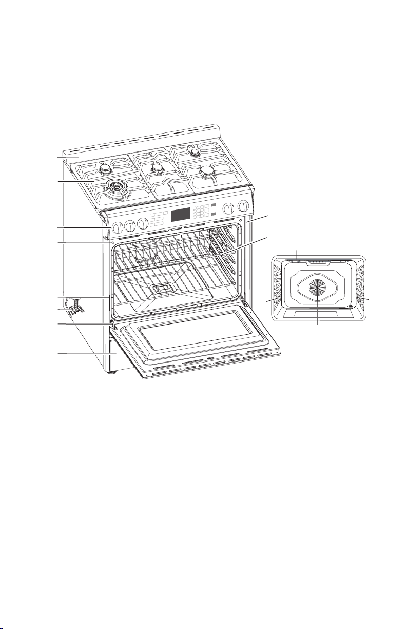
PARTS AND FEATURES
have some or all of the items listed. The locations and appearances of the features
shown here may not match those of your model.
a
b
c
d
i
j
e
f
g
h
l
l
k
m
a Backsplash
b Burner Grates
c Control Panel
d Oven Door Lock Latch and
Light Switch
e Model and Serial Number Plate
f Anti-tip Bracket
g Door Hinge
h Decorative Drawer
i Door Gasket
j Oven Rack
k Broil Element
l Oven Light
m Convection Fan and Element
9
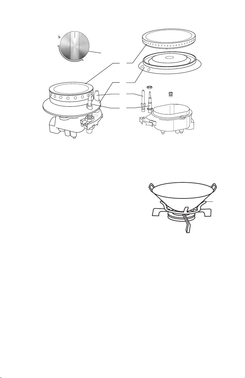
MAX
MIN
a
OFF
b
c
d
e
a
b Burner Cap
c Burner Head
d Electrode
e Flame Detector (On Some Models)
Accessory
pans supported with the wok ring (provided) can be
used with all models.
a
a Wok Ring
10
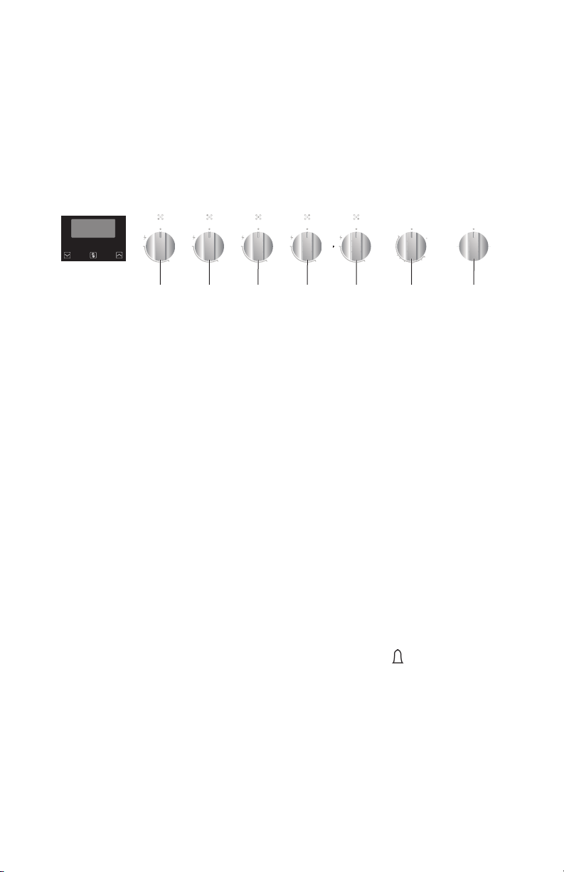
CONTROL PANEL
36" MODELS
MAX
OFF
MIN
MAX
OFF
MIN
MAX
OFF
MIN
MAX
OFF
MIN
MAX
OFF
MIN
°
F
MIN
OFF
OFF
LightConvection
Broil
MAX
300
350
400
450
325
a b c d e gf
a Front Left Burner
b Rear Left Burner
c Center Burner
d Rear Right Burner
e Front Right Burner
f Temperature Control
g Features Control
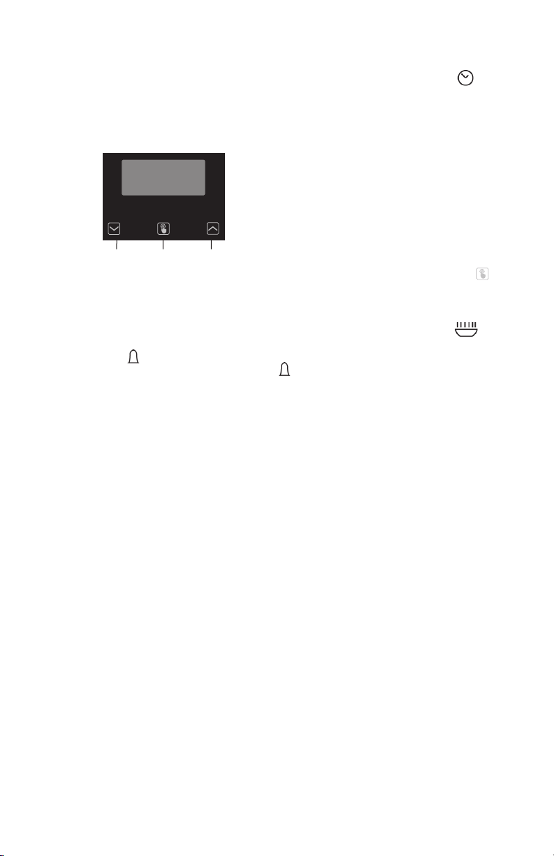
CLOCK AND TIMER
Your model has a digital display, 12-hour clock with three Control buttons.
IMPORTANT: In the event of a power failure, all settings including the time
display will be lost. When the power is returned, the bar above and 12:00 will be
displayed.
Timer
Set
Cook
Time
End
Time
Set
Clock
11
TIME OF DAY
When the power is connected, the screen displays 12:00 and the bar above
To set the correct time, press the "-" or "+" button until the correct time is
displayed. After 5 seconds, the clock will start automatically, or you can press
the function button to select manual operation.
a b c
a Decrease Time
b Function
c Increase Time
SET THE TIMER
1
To set the timer, press the function button repeatedly until the bar above
is displayed. Once the function button is released, the current time is displayed and
time is
displayed. When the set time is reached, disappears and the alarm will ring. To
stop the alarm, press any button.
NOTE: After pressing the function button, you must set the timer within 5 seconds.
Timer
Set
Cook
Time
End
Time
Set
Clock

12
COOKTOP USE
Read the instructions before installing or using this appliance.
1. This appliance shall be installed in accordance with the regulations in force and
only used in a well-ventilated space.
2. The use of a gas-cooking appliance results in the production of heat and
moisture in the room in which it is installed. Ensure that the kitchen is well
ventilated: keep natural ventilation holes open or install a mechanical ventilation
3. Prolonged intensive use of the appliance may call for additional ventilation,
increasing the level of mechanical ventilation where present.
IGNITION AND OPERATION OF THE BURNERS
In order to ignite a burner, push down on the knob while rotating it counterclockwise,
until the knob indicator is aligned with the ignite icon
.
for about 3-4 seconds until the device keeps the burner automatically lit. If the
burner fails to ignite, wait one minute for the gas to dissipate before attempting to
aligned with OFF.
POWER FAILURE
In case of prolonged power failure, the surface burners can be lit manually. Hold a lit
match near a burner and turn knob counterclockwise until the indicator is aligned
The electric igniter must not be actuated for longer than 15 seconds. Should the
For lower gas consumption and a better result, use saucepans with a diameter
boiling.
13
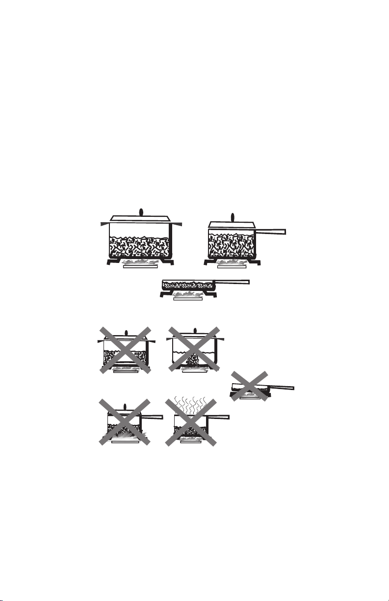
COOKWARE
MATCH PAN DIAMETER TO FLAME SIZE
Oversize pans that span two burners are placed front to rear, not side to side.
USE BALANCED PANS
Pans must sit level on the cooktop grate without rocking. Center the pan over the
burner.
USE A LID THAT FITS PROPERLY
even heat and stability.
BALANCED PAN
UNBALANCED PAN
CONVEX
(ROUNDED)
CONCAVE
(HOLLOW)
FLAME TOO LARGE
FOR PAN SIZE
USE LIDS THAT
FIT PROPERLY

14
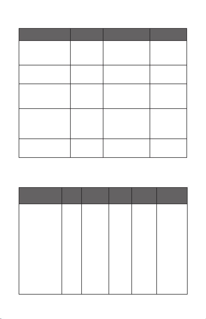
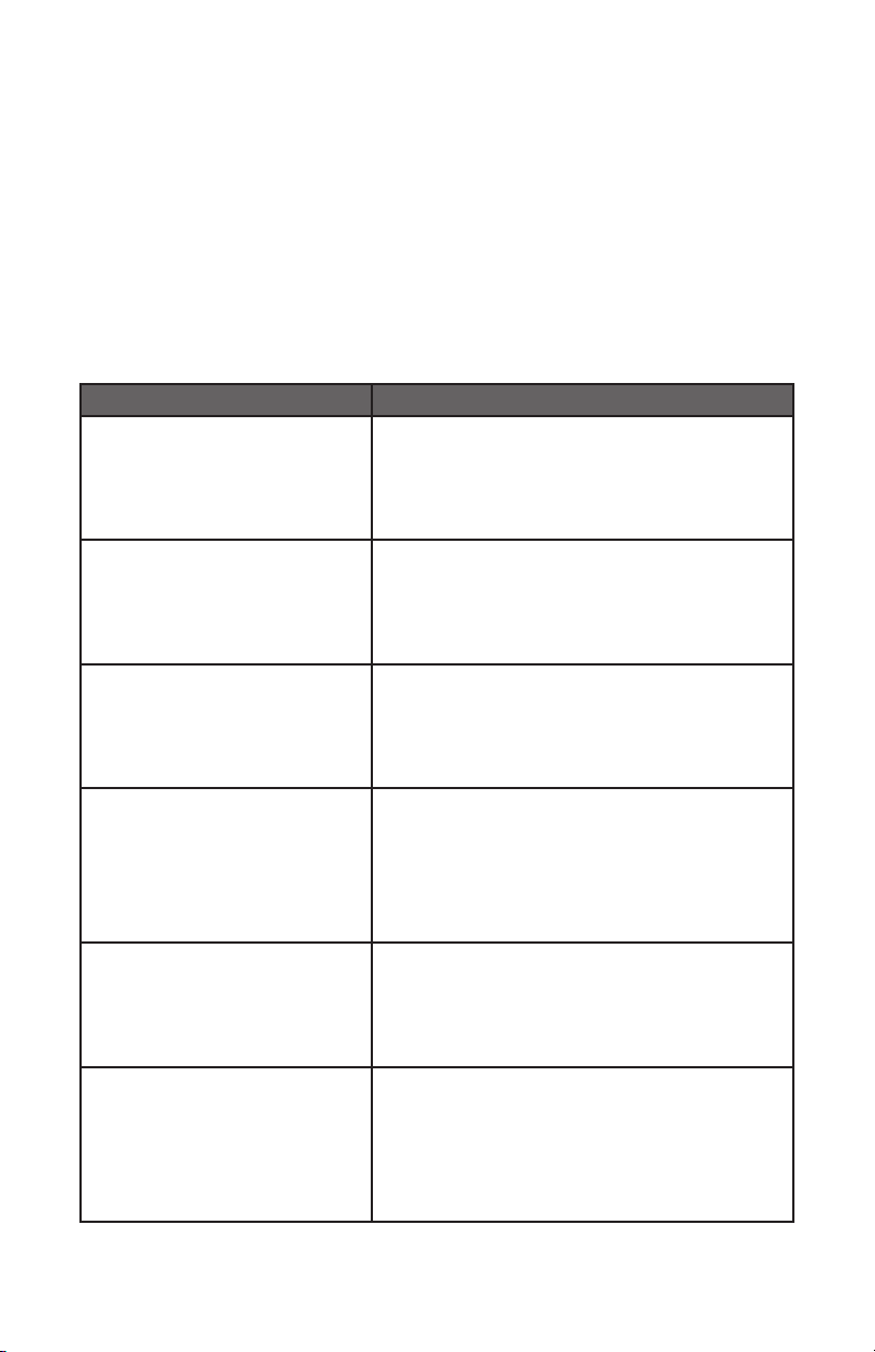
CONTAINER TABLE
Burner Min Saucepan Max Saucepan
3.5” (9.0 cm) 6.3” (16 cm)
Semi-rapid 5.1” (13 cm) 7.1” (18 cm)
Rapid 5.9” (15 cm) 10.2” (26 cm)
Triple ring 8.3” (21 cm) 10.2” (26 cm)
OVEN USE
COOKING WITH THE GAS OVEN
BAKING AND ROASTING
This oven features a gas burner located under the oven cavity which provides evenly
distributed heat from the bottom of the oven. The heat rises naturally to bake food
evenly.
BROILING
This oven features a gas burner located at the top of the oven cavity which provides
evenly distributed heat from the top of the oven.
position.
TEMPERATURE CONTROL
The Temperature knob is used to select either the Bake or Broil Oven Mode.
BAKE
•
Push in on the Temperature knob, and then turn the knob counterclockwise to
automatically ignite the bake burner. Continue turning the knob to select the
BROIL
•
Push in on the Temperature control knob, and then turn the knob clockwise to
automatically ignite the broil burner.
NOTE: The broil burner will remain on until the Temperature control is returned
to the OFF position.

15
FEATURES CONTROL
Light
The oven cavity light turns ON automatically, when the Bake or Broil function is
selected, and remains on during operation.
Conv (Convection) Fan
During convection cooking, the fan provides hot air circulation throughout the
oven. The movement of heated air around the food can help to speed up cooking
by penetrating the cooler outer surfaces. Food cooks more evenly, browning and
crisping outer surfaces while sealing moisture inside.
OVEN TIPS AND TECHNIQUES
Baking is cooking with heated air. The lower bake burner is on which heats the air in
the oven cavity, baking the food with naturally circulating hot air currents.
Follow the recipe or convenience food directions for baking temperature, time and
rack position. Baking time will vary with the temperature of ingredients and the size,
General Guidelines
•
For best results, bake food on a single rack with at least 1” - 1 ½” (2,5 - 3 cm)
space between utensils and oven walls.
•
Use one rack when selecting the bake mode.
•
Check for doneness at the minimum time.
•
Use metal bake ware (with or without a non stick
ceramic, pottery or other utensils suitable for the oven.
•
When using heatproof glass, reduce temperature by 25°F (15°C) from
recommended temperature.
•
•
Dark metal pans or nonstick coatings will cook faster with more browning.
Insulated bake ware will slightly lengthen the cooking time for most foods.
•
Do not use aluminum foil or disposable aluminum trays to line any part of the
•
Avoid using the opened door as a shelf to place pans.
•
See Troubleshooting for tips to Solving Baking and Roasting Problems.
16
BAKE CHART
FOOD ITEM
RACK
POSITION
TEMP. °F (°C)
(PREHEATED OVEN)
TIME (MIN)
Cake
Cupcakes
Bundt Cake
Angel Food
2
1
1
350 (175)
350 (175)
350 (175)
19-22
40-45
35-39
Pie
2 crust, fresh, 9”
2 crust, frozen fruit, 9”
2
2
375-400 (190-205)
375 (190)
45-50
68-78
Cookies
Sugar
Chocolate Chip
Brownies
2
2
2
350-375 (175-190)
350-375 (175-190)
350 (175)
8-10
8-13
29-36
Breads
Yeast rolls
Biscuits
2
2
2
2
375 (190)
375-400 (190-205)
375-400 (190-205)
425 (220)
18-22
12-15
7-9
15-19
Pizza
Frozen
Fresh
2
2
400-450 (205-235)
475 (246)
23-26
15-18
•
See Troubleshooting for tips to Solving Baking and Roasting Problems.
ROAST CHART
Roast should typically be 20 minutes per pound at 350°F (175°C).
MEATS
WEIGHT
(lb)
OVEN TEMP.
°F (°C)
RACK
POSITION
TIME
(min. per
lb)
INTERNAL
TEMP. °F (°C)
Beef
Rib Roast 4-6 325 (160) 2 16-20
18-22
145 (63)
medium rare
160 (71)
medium
Rib Eye Roast,
(boneless)
4-6 325 (160) 2 16-20
18-22
145 (63)
medium rare
160 (71)
medium
Rump, Eye, Tip,
Sirloin (boneless)
3-6 325 (160) 2 16-20
18-22
145 (63)
medium rare
160 (71)
medium
Tenderloin Roast 2-3 400 (205) 2 15-20 145 (63)
medium rare
17
MEATS
WEIGHT
(lb)
OVEN TEMP.
°F (°C)
RACK
POSITION
TIME
(min. per
lb)
INTERNAL
TEMP. °F (°C)
Pork
Loin Roast
(boneless or bone-
in)
5-8 350 (175) 2 16-20 160 (71)
medium
Shoulder 3-6 350 (175) 2 20-25 160 (71)
medium
Poultry
Chicken whole 3-4 375 (190) 2 18-21 180 (82)
12-15 325 (160) 1 10-14 180 (82)
16-20 325 (160) 1 9-11 180 (82)
21-25 325 (160) 1 6-10 180 (82)
Turkey Breast 3-8 325 (160) 1 15-20 170 (77)
Cornish Hen 1-1 ½ 350 (175) 2 45-75
total
180 (82)
Lamb
Half Leg 3-4 325 (160) 2 22-27
28-33
160 (71)
medium
170 (77) well
Whole Leg 6-8 325 (160) 1 22-27
28-33
160 (71)
medium
170 (77) well
BROIL CHART
FOOD AND THICKNESS
RACK
POSITION
INTERNAL
TEMP. °F (°C)
TIME SIDE
1 (MIN.)*
TIME SIDE
2 (MIN.)*
Beef
Steak (1-½” or more)
Medium rare 4 145 (65) 9-12 8-10
Medium 4 160 (71) 11-13 10-12
Well 4 170 (77) 18-20 16-17
Hamburgers (more than 1”)
Medium 4 160 (71) 8-11 5-7
Well 4 170 (77) 11-13 8-10
Poultry
Chicken Quarters 4 180 (82) 16-18 10-13
Chicken Halves 3 180 (82) 25-27 15-18
Chicken Breasts 4 170 (77) 13-15 9-13
Pork
Pork Chops (1¼” or more) 4 160 (71) 12-14 11-13
Sausage - fresh 4 160 (71) 4-6 3-5

18
RANGE CARE
CLEANING
IMPORTANT:
cooktop are cool. Always follow label instructions on cleaning products. Soap, water
abrasive cleaning products.
EXTERIOR PORCELAIN ENAMEL SURFACES
Food spills containing acids, such as vinegar and tomato, should be cleaned as soon
Cleaning Method:
Glass cleaner, mild liquid cleaner or nonabrasive scrubbing pad: Gently clean around
the model and serial number plate because scrubbing may remove numbers.
EXTERIOR STAINLESS STEEL
NOTE:
Cream, steel-wool pads, gritty washcloths or some paper towels. Damage may
occur, even with one-time or limited use.
Rub in direction of grain to avoid damaging.
Cleaning Methods:
Liquid detergent or all-purpose cleaner: Rinse well with clean water and dry with
soft, lint-free cloth.
Stainless Steel Cleaner and Polish
Vinegar for hard water spots
OVEN DOOR EXTERIOR
Cleaning Method:
Glass cleaner and paper towels or nonabrasive plastic scrubbing pad: Apply glass
cleaner to soft cloth or sponge, not directly on panel.
PORCELAIN-COATED GRATES AND CAPS
•
Clean as soon as cooktop, grates and caps are cool.
•
Food spills containing acids, such as vinegar and tomato, should be cleaned as
•
To avoid chipping, do not bang grates and caps against each other or hard
surfaces such as cast iron cookware.
•
Do not reassemble caps on burners while wet.
Cleaning Method:
Nonabrasive plastic scrubbing pad and mildly abrasive cleanser

19
BURNER SPREADER
Wash the burner spreader frequently with boiling water and detergent to remove
Before reinstalling, dry the burner spreader thoroughly so the burner will ignite
properly.
COOKTOP CONTROL KNOBS
•
Pull knobs straight away from control panel to remove.
•
Cleaning Method:
Soap and water or dishwasher:
NOTE: Do not use steel wool, abrasive cleansers or oven cleaner. Do not soak
knobs.
CONTROL PANEL
Cleaning Method:
Glass cleaner and soft cloth or sponge: Apply glass cleaner to soft cloth or sponge,
not directly on panel.
NOTE: Do not use abrasive cleaners, steel-wool pads, gritty washcloths or some
paper towels. Damage may occur.
OVEN CAVITY
Food spills should be cleaned when oven cools. At high temperatures, foods react
with porcelain, so staining, etching, pitting or faint white spots can result.
Cleaning Method:
Mild detergent and warm water.
NOTE: Do not use oven cleaners.
OVEN RACKS AND ROASTING RACKS
Cleaning Method:
Steel-wool pad
BROILER PAN
Cleaning Method:
Mildly abrasive cleanser: Scrub with wet scouring pad.
Solution of ½ cup (125 mL) ammonia to 1 gal. (3.75 L) water: Soak for 20 minutes,
and then scrub with scouring or steel-wool pad.
Oven cleaner: Follow product label instructions. Porcelain enamel only, not chrome
Dishwasher
20
TROUBLESHOOTING
First try the solutions suggested here to possibly avoid the cost of a service call.
BAKING AND ROASTING PROBLEMS
With any oven setting poor results can occur for many reasons other than a
malfunction of the oven. Check the chart below for causes of the most common
baking results, the best solution may be to replace old baking utensils that have
darkened and warped with age and use.
Baking Problem Cause
Food browns unevenly
•
Oven not preheated
•
Aluminum foil on oven rack or oven bottom
•
Baking utensil too large for recipe
•
Pans touching each other or oven walls
Food too brown on bottom
•
Oven not preheated
•
Using glass, dull or darkened metal pans
•
Incorrect rack position
•
Pans touching each other or oven walls
Food is dry or has shrunk
•
Oven temperature too high
•
Baking time too long
•
Oven door opened frequently
•
Pan size too large
Food is baking or roasting too
slowly
•
Oven temperature too low
•
Oven not preheated
•
Oven door opened frequently
•
Tightly sealed with aluminum foil
•
Pan size too small
Pie crusts do not brown on
bottom or crust is soggy
•
Baking time not long enough
•
Using shiny steel pans
•
Incorrect rack position
•
Oven temperature is too low
done inside
•
Oven temperature too low
•
Incorrect baking time
•
Cake tested too soon
•
Oven door opened too often
•
Pan size may be too large
21
Cakes high in middle with crack
on top
•
Oven temperature too high
•
Baking time too long
•
Pans touching each other or oven walls
•
Incorrect rack position
•
Pan size too small
Pie crust edges too brown
•
Oven temperature too high
•
Edges of crust too thin
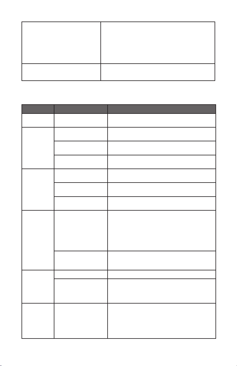
COOKTOP
PROBLEM POSSIBLE CAUSE SOLUTION
Burner will
not ignite
There is no power to
the cooktop
Plug into a grounded 3 prong outlet. Replace
fuse or reset circuit breaker.
Burner
will not
operate
First time use. Air
still in the gas line.
Turn on any one of the surface burner knobs
to release air from the gas lines.
Control knob is not
set correctly.
Push in knob before turning to a setting.
The burner port is
clogged.
toothbrush or a straightened paper clip.
Burner
Flames are
uneven,
yellow and/
or noisy
Burner port(s) are
clogged.
toothbrush or a straightened paper clip.
Burner caps are not
positioned properly.
Place burner caps so that the alignment pins
are properly aligned with the slots.
Propane gas is being
used.
The range should be converted to LP gas by
Burner
ame is too
high or too
low
Cooktop gas supply
is not correct.
Ensure the range is set for the correct
gas type. It is factory set for natural gas. If
connected to LP gas the burners should be
kit supplied and the pressure regulator
technician.
The gas pressure is
not correct.
Make sure the pressure regulator is installed
correctly and the gas line pressure is correct.
See Installation Instructions.
Burner
makes
popping
noises
The burner is wet. Allow the burner to dry before using.
The burner cap and/
or gas spreader
is not positioned
correctly.
Place burner caps so that the alignment pins
are properly aligned with the slots.
Excessive
heat
around
cookware
on cooktop
The cookware is not
the proper size for
the burner.
Use cookware with a bottom surface
area and burner. Cookware should not
does not come up around the cookware.
22
Cooking
results are
not what
expected
Using incorrect
cookware
See the “Cookware” section.
The control knob is
not set to the proper
heat level.
See the “Controls” section.
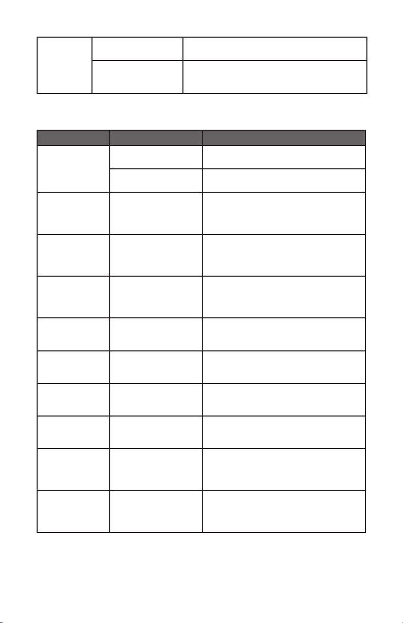
OVEN
PROBLEM POSSIBLE CAUSE SOLUTION
Oven is not
heating
No power to the
oven
Reset the circuit breaker or replace the
Oven control not
turned on
Make sure the oven temperature has
been selected.
Oven is not
cooking evenly
Not using the correct
bake ware or oven
rack position
Refer to cook charts for recommended
rack position. Always reduce recipe
temperature by 25 °F (15 °C) when
baking with Convention Bake mode.
Oven display
stays O.
Power interruption
breaker back on. If condition persists,
call for service.
Cooling fan
continues to
run after oven
is turned o
The electronic
components have
not yet cooled
when the electronic components have
Oven light is
not working
properly
Light bulb loose or
burned-out.
Reinsert or replace the light bulb.
cause the bulb to burn out.
Oven light
stays on
Door is not closing
completely
Check for obstruction in oven door.
Check to see if hinge is bent or door
switch broken.
Cannot remove
lens cover
Soil build-up around
the lens cover.
Wipe lens cover area with a clean, dry
towel prior to attempting to remove
the lens cover.
Clock and timer
are not working
properly
No power to the
oven
Reset the circuit breaker or replace the
Excessive
Moisture
When using bake mode, preheat
Convection Roast will eliminate any
moisture in the oven.
Porcelain Chips
Porcelain interior
is bumped by oven
racks
When removing and replacing oven
racks, always tilt racks upward and do
not force them to avoid chipping the
porcelain.

23