Loading ...
Loading ...
Loading ...
LAUNCH X-431 V User Manual — Vehicle Diagnosis
15
4.3 Connections
4.3.1 Preparation
Normal testing conditions
y
Turn on the vehicle power supply.
y
Vehicle battery voltage range should be 9-14 Volts.
y
Throttle should be in a closed position.
Select the diagnostic connector
If X-431 V is testing vehicles equipped with universal OBD II 16 PIN diagnostic
socket, please use the included diagnostic connector. (For vehicles with
non-OBD II 16 PIN diagnostic socket, a non-16 PIN connector is required.)
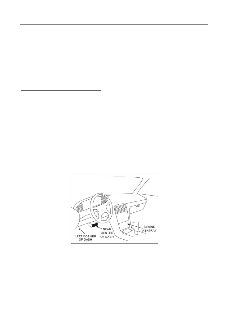
4.3.2 DLC location
The DLC (Data Link Connector or Diagnostic Link Connector) is typically a
standard 16-pin connector where diagnostic tools interface with a vehicle’s
on-board control modules. The DLC is usually located 12 inches from the center
of the instrument panel, under or around the driver’s side for most vehicles. If
Data Link Connector is not located under dashboard, a label should be there
telling location. For some Asian and European vehicles, the DLC is located
behind the ashtray and the ashtray must be removed to access the connector. If
the DLC cannot be found, refer to the vehicle’s service manual for the location.
Fig. 4-9
4.3.3 Vehicle connection
The method used to connect the diagnostic connector to a vehicle’s DLC
depends on the vehicle’s configuration as follows:
y
A vehicle equipped with an OBD II management system supplies both
communication and 12V power through a standardized DLC.
y
A vehicle not equipped with an OBD II management system supplies
Loading ...
Loading ...
Loading ...