Loading ...
Loading ...
Loading ...
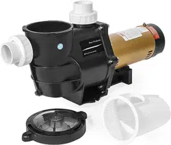
WIRING DIAGRAM
This is how the pump should be wired when it is received.
On the wiring diagram, you see the colors black and yellow
pointing to the wiring locations. These spots are for pumps
intenal black and yellow wires only. This is only used for
reference in the instance that a wire comes off its post.
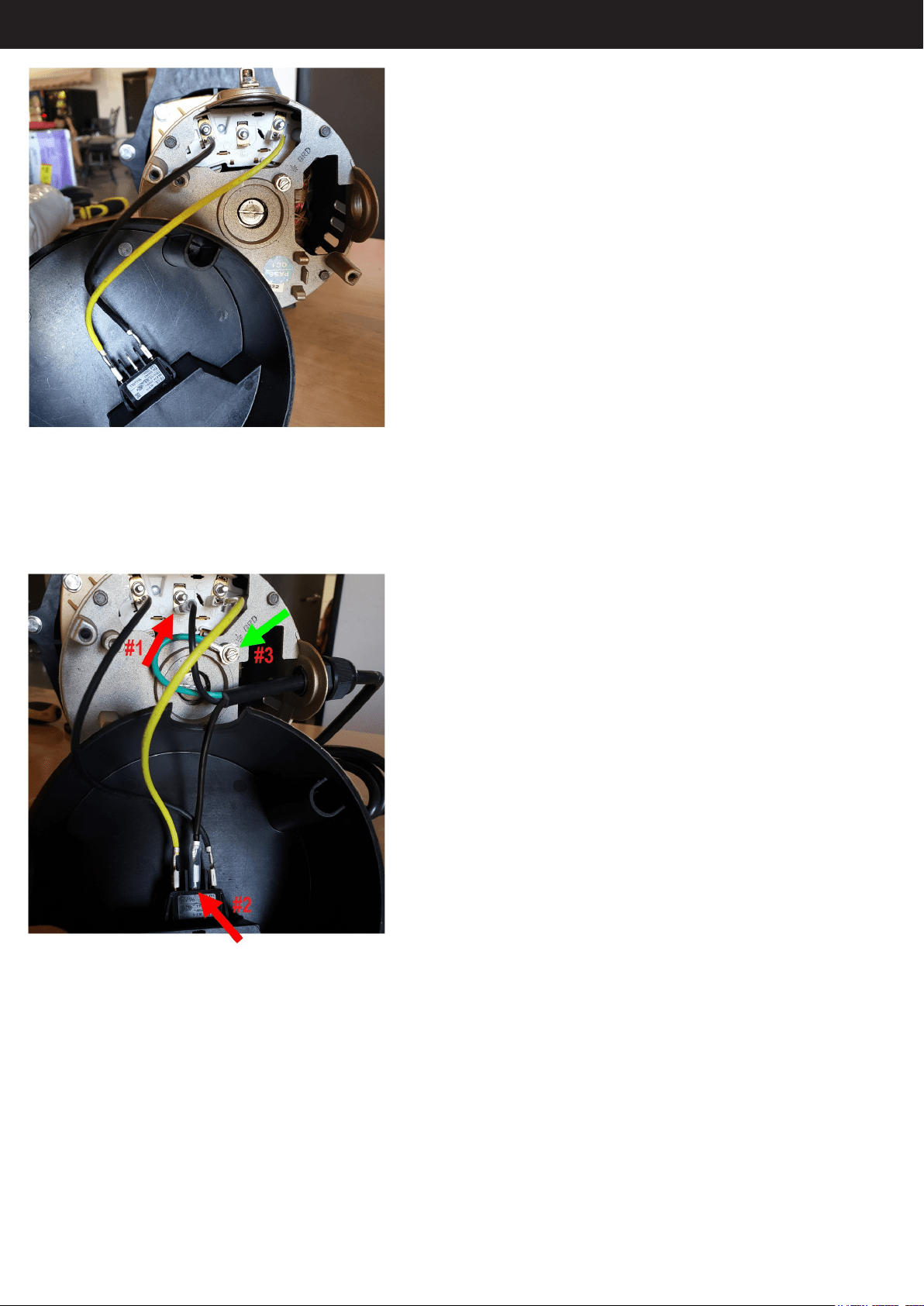
Your wires attach where the diagram shows “line”. These are
empty posts on the pump and cover. NEVER have your wire
on the same post as an internal wire.
TO ATTACH YOUR WIRES, FOLLOW THESE STEPS:
1. Slip one HOT 110/115V wire onto the center post on the
back of the pump. (red arrow #1)
2. Slip the other HOT 110/115V wire onto the center post on
the cover. (red arrow #2)
3. Attach your ground wire (if you have one) to either the top of
the pump on the green nut, or on the back of the pump where
it says “GRD”. (green arrow #3)
11
Loading ...
Loading ...
Loading ...