OWNER'S MANUAL
CAUTION
RISKOFELECTRICSHOCK
DONOTOPEN
CAUTION: TO REDUCE THE RISK OF
ELECTRIC SHOCK, DO NOT REMOVE
COVER (OR BACK). NO USER-SERVICEABLE
PARTS INSIDE. REFER SERVICING TO
QUALIFIED SERVICE PERSONNEL.
• Explanation of Graphical Symbols
The lightning flash with arrowhead symbol,
within an equilateral triangle, is intended to
alert you to the presence of uninsulated
"dangerous voltage" within the product's
enclosure that may be of sufficient magnitude
to constitute a risk of electric shock to
persons.
The exclamation point within an equilateral
triangle is intended to alert you to the
presence of important operating and
maintenance (servicing) instructions in the
literature accompanying the appliance.
l Read these instructions.
2 Keep these instructions.
3 Heed all warnings.
4 Follow all instructions.
5 Do not use this apparatus near water.
6 Clean only with dry cloth.
7 Do not block any ventilation openings. Install in accordance with
the manufacturer's instmctious.
8 Do not install near any heat sources such as radiators, heat
registers, stoves, or other apparatus (including amplifiers) that
produce heat.
9 Do not defeat the safety purpose of the polarized or grounding-
type plug. A polarized plug has two blades with one wider than
the other. A grounding type plug has two blades and a third
grounding prong. The wide blade or the third prong are provided
for your safety. If the provided plug does not fit into your outlet,
consult an electrician for replacement of the obsolete outlet.
10 Protect the power cord from being walked on or pinched
particularly at plugs, convenience receptacles, and the point
where they exit from the apparatus.
11 Only use attachments/accessories specified by the manufacturer.
12 Use only with the cart, stand, tripod, bracket,
or table specified by the manufacturer, or
sold with the apparatus. When a cart is used,
use caution when moving the cart/apparatus
combination to avoid injury from tip-over.
13 Unplug this apparatus during lightning
storms or when unused for long periods of time.
14 Refer all servicing to qualified service personnel. Servicing is
required when the apparatus has been damaged in any way, such
as power supply cable or plug is damaged, liquid has been spilled
or objects have fallen into the apparatus, the apparatus has been
exposed to rain or moisture, does not operate normally, or has
been dropped.
i En
._l'.re]:|l-,VAvlllk'f:V._:ll'lhVl.'_l_|l.r_l[o]_, _
FCC INFORMATION (for US customers)
1. IMPORTANT NOTICE: DO NOT MODIFY THIS UNIT!
This product, when installed as indicated in the instructions
contained in this manual, meets FCC requirements.
Modifications not expressly approved by Yamaha may void
your authority, granted by the FCC, to use the product.
2. IMPORTANT:
When connecting this product to accessories and/or another
product use only high quality shielded cables. Cable/s supplied
with this product MUST be used. Follow all installation
instructions. Failure to follow instructions could void your FCC
authorization to use this product in the USA.
3. NOTE:
This product has been tested and found to comply with the
requirements listed in FCC Regulations, Part 15 for Class "B"
digital devices. Compliance with these requirements provides a
reasonable level of assurance that your use of this product in a
residential environment will not result in harmful interference
with other electronic devices.
This equipment generates/uses radio frequencies and, if not
installed and used according to the instructions found in the
users manual, may cause interference harmful to the operation
of other electronic devices.
Compliance with FCC regulations does not guarantee that
interference will not occur in all installations. If this product is
found to be the source of interference, which can be determined
by turning the unit "OFF" and "ON", please try to eliminate the
problem by using one of the following measures:
Relocate either this product or the device that is being affected
by the interference.
Utilize power outlets that are on different branch (circuit
breaker or fuse) circuits or install AC line filter/s.
In the case of radio or TV interference, relocate/reorient the
antenna. If the antenna lead-in is 300 ohm ribbon lead, change
the lead-in to coaxial type cable.
If these corrective measures do not produce satisfactory results,
please contact the local retailer authorized to distribute this type
of product. If you can not locate the appropriate retailer, please
contact Yamaha Electronics Corp., U.S.A. 6660 Orangethorpe
Ave, Buena Park, CA 90620.
The above statements apply ONLY to those products distributed
by Yamaha Corporation of America or its subsidiaries.
We Want You Listening For A Lifetime
Yamaha and the Electronic Industries Association's Consumer Electronics Group want you to get the most out of your
equipment by playing it at a safe level. One that lets the sound come through loud and clear without annoying
blaring or distortion - and, most importantly, without affecting your sensitive hearing.
Since hearing damage from loud sounds is often undetectable until it is too late, Yamaha and the Electronic Industries
Association's Consumer Electronics Group recommend you to avoid prolonged exposure from excessive volume levels. _.mrmmcG
iq_Al, nmmm_
JJEn
1 To assure the finest performance, please read this manual
carefully. Keep it in a safe place for future reference.
2 Install this sound system in a well ventilated, cool, dry, clean
place with at least 5 cm (2 in) of space above (or below) this unit
- away from direct sunlight, heat sources, vibration, dust,
moisture, and/or cold.
3 Locate this unit away from other electrical appliances, motors, or
transformers to avoid humming sounds.
4 Do not expose this unit to sudden temperature changes from cold
to hot, and do not locate this unit in an environment with high
humidity (i.e. a room with a humidifier) to prevent condensation
inside this unit, which may cause an electrical shock, fire,
damage to this unit, and/or personal injury.
5 Avoid installing this unit where foreign object may fall onto this
unit and/or this unit may be exposed to liquid dripping or
splashing. On the top of this unit, do not place:
- Other components, as they may cause damage and/or
discoloration on the surface of this unit.
- Burning objects (i.e. candles), as they may cause fire, damage
to this unit, and/or personal injury.
- Containers with liquid in them, as they may fall and liquid
may cause electrical shock to the user and/or damage to this
unit.
6 Do not cover this unit with a newspaper, tablecloth, curtain, etc.
in order not to obstruct heat radiation. If the temperature inside
this unit rises, it may cause fire, damage to this unit, and/or
personal injury.
7 Do not plug in this unit to a wall outlet until all connections are
complete.
8 Do not operate this unit upside-down. It may overheat, possibly
causing damage.
9 Do not use force on switches, knobs and/or cords.
10 When disconnecting the power supply cable from the wall outlet,
grasp the plug; do not pull the cable.
11 Do not clean this unit with chemical solvents; this might damage
the finish. Use a clean, dry cloth.
12 Only voltage specified on this unit must be used. Using this unit
with a higher voltage than specified is dangerous and may cause
fire, damage to this unit, and/or personal injury. Yamaha will not
be held responsible for any damage resulting from use of this unit
with a voltage other than specified.
13 To prevent damage by lightning, keep the power supply cable
disconnected from a wall outlet or this unit during a lightning
stoHn.
14 Do not attempt to modify or fix this unit. Contact qualified
Yamaha service personnel when any service is needed.
The cabinet should never be opened for any reasons.
15 When not planning to use this unit for long periods of time (i.e.
vacation), disconnect the power supply cable from the wall
outlet.
16 Be sure to read the "Troubleshooting" section on common
operating errors before concluding that this unit is faulty.
17 Before moving this unit, press STANDBY/ON to set this unit in
standby mode, and disconnect the power supply cable from the
wall outlet.
18 Condensation will form when the surrounding temperature
changes suddenly. Disconnect the power supply cable from the
outlet, then leave the unit alone.
19 When using the unit for a long time, the unit may become warm.
Turn the power off, then leave the unit alone for cooling.
20 Install this unit near the AC outlet and where the AC power plug
can be reached easily.
21 The batteries shall not be exposed to excessive heat such as
sunshine, fire or the like.
WARNING I
TO REDUCE THE RISK OF FIRE OR ELECTRIC SHOCK, DO
NOT EXPOSE THIS UNIT TO RAIN OR MOISTURE.
This unit is not disconnected from the AC power source as long as
it is connected to the AC wall outlet, even if this unit itself is
turned off by STANDBY/ON. This state is called the standby
mode. In this state, this unit is designed to consume a very small
quantity of power.
IMPORTANT
Please record the serial number of this unit in the space below.
MODEL:
Serial No.:
The serial number is located on the rear of the unit. Retain this
Owner's Manual in a safe place for future reference.
FOR CANADIAN CUSTOMERS
To prevent electric shock, match wide blade of plug to wide slot
and fully insert.
This Class B digital apparatus complies with Canadian ICES-003.
POUR LES CONSOMMATEURS CANADIENS
Pour 6viter les chocs 6lectriques, introduire la lame la plus
large de la fiche dans la borne correspondante de la prise et
pousser jusqu'au fond.
Cet appareil num6rique de la classe Best conforme _ la norme
NMB-003 du Canada.
CAUTION
Danger of explosion if battery is incorrectly replaced. Replace
only with the same or equivalent type.
CAUTION
Use of controls or adjustments or performance of procedures other
than those specified herein may result in hazardous radiation
exposure.
=mm
III En
Overview .................................................................. 2
Features ................................................................... 3
Using this manual ................................................... 5
Supplied accessories ............................................... 6
Controls and functions ........................................... 7
Front panel ................................................................. 7
Front panel display .................................................... 8
Rear panel .................................................................. 9
Remote control ......................................................... 10
Installation ............................................................. 13
Before installing this unit......................................... 13
Installing this unit .................................................... 13
Connections ........................................................... 16
Before connecting components ................................ 17
Case 1: Connections using HDMI cables ................ 18
Case 2: Connecting a DVD player/recorder and tuner
(digital satellite, cable TV or digital airwave) ..... 19
Case 3: Connecting other connection methods ........ 20
Connecting a TV without an HDMI cable ............... 21
Connecting a portable audio player ......................... 22
Connecting a subwoofer .......................................... 22
Connecting the FM antenna ..................................... 23
About the IR IN jack ................................................ 23
Connecting the AC power supply cable .................. 23
Getting started ...................................................... 24
Installing batteries in the remote control ................. 24
Operation range of the remote control ..................... 24
Turning on this unit or
setting it to the standby mode .............................. 25
Using SET MENU ................................................. 26
Displaying the OSD (on-screen display) ................. 26
The flow chart of SET MENU ................................. 27
Changing OSD language ...................................... 28
AUTO SETUP (lntelliBeam) ............................... 29
The flow chart of AUTO SETUP ............................ 29
Installing the IntelliBeam microphone .................... 30
Using AUTO SETUP (IntelliBeam) ........................ 31
Using the system memory .................................... 36
Convenient usage of the system memory ................ 36
Saving settings ......................................................... 36
Loading settings ....................................................... 37
Playback ................................................................ 39
Selecting the input source ........................................ 39
Playing back sources ................................................ 40
Adjusting the volume ............................................... 41
FM tuning .............................................................. 42
FM controls and functions ....................................... 42
Automatic tuning ..................................................... 43
Manual tuning .......................................................... 43
Automatic preset tuning ........................................... 44
Manual preset tuning ............................................... 45
Selecting a preset station ......................................... 46
XM TM Satellite Radio tuning ............................... 47
Connecting XMTM Mini-Tuner Home Dock ........... 47
Activating XM TM Satellite Radio ............................ 48
Basic XM TM Satellite Radio operations ................... 48
Presetting the XM TM Satellite Radio channels ........ 51
Displaying the XM TM Satellite Radio information.... 52
Using iPod TM .......................................................... 53
Connection ............................................................... 53
Controlling iPod TM ................................................... 53
Enjoying surround sound ..................................... 56
5 Beam ..................................................................... 56
Stereo plus 3 Beam .................................................. 57
3 Beam ..................................................................... 57
My Surround ............................................................ 57
Enjoying 2-channel sources
in surround sound ................................................ 59
Enjoying TV in surround sound .............................. 60
Adjusting surround mode parameters ...................... 61
Enjoying stereo sound ........................................... 62
2-channel stereo playback ........................................ 62
5-channel stereo playback ........................................ 62
Playing back sound clearly (My Beam) ............... 63
Using auto-adjust function ....................................... 63
Using manual-adjust function .................................. 64
Using sound field programs .................................. 65
CINEMA DSP programs ......................................... 66
Using the music enhancer ..................................... 68
Using the volume mode
(Night listening enhancer/TV volume equal
mode) .................................................................. 69
Using the sleep timer ............................................. 70
Displaying the input source information ............. 72
Using the HDMI control feature .......................... 73
MANUAL SETUP ................................................. 74
Using MANUAL SETUP ....................................... 75
BEAM MENU ......................................................... 76
SOUND MENU ....................................................... 80
INPUT MENU ......................................................... 82 1
DISPLAY MENU .................................................... 86
Adjusting the audio balance ................................. 87
Using the test tone ................................................... 87
Using the audio output being played back ............... 88
Selecting the input mode ....................................... 90
Adjusting the system parameters ........................ 91
Using the system parameters ................................... 91
Remote control features ........................................ 94
Setting remote control codes ................................... 94
Controlling other components ................................. 95
Using the TV macro ................................................ 98
I .................!06_
I Specifications ................................................... 107
List of remote control codes ............................................. i I /
1En
DigitalSoundProjectorTM
The Digital Sound Projector technology allows one slim
unit to control and steer multiple channels of sound to
generate multi-channel surround sound, thus eliminates
the need for satellite loudspeakers and cabling normally
associated with conventional surround sound systems.
This unit also employs the beam modes that let you enjoy
the surround sound (5 Beam, Stereo plus 3 Beam and 3
Beam), 2-channel and 5-channel stereo playback, and My
Beam.
My Surround
In addition to the above mentioned beam modes, this unit
is equipped with My Surround beam mode that allows you
to enjoy surround system even in a small listening area.
My Surround is a function integrated and optimized with
DiMAGIC's Euphony technology and Yamaha's Beam
reproduction system.
My Beam
This unit employs My Beam that ensures a clear sound in
a noisy environment. You can adjust the beam angle
manually or automatically.
Cinema DSP
This unit employs the Cinema DSP technology developed
by Yamaha Corporation that lets you experience movies at
home with all the original dramatic sound impact.
HDMI TM (High-Definition Multimedia Interface)
• HDMI interface for standard, enhanced, or high-definition
video (including 1080p video signal transmission) as well as
multi-channel digital audio based on HDCP
• Simple and easy connections with HDMI supported external
components
• Functional link with an HDMI control-compatible TV
• Analog video up-scaling from 480i (NTSC)/576i (PAL) or
480p (NTSC)/576p (PAL) to 720p or 1080i
Versatile Remote Control
The supplied remote control comes with preset remote
control codes used to control the DVD player, VCR, cable
TV tuner, and digital satellite tuner connected to this unit.
In addition, the remote control is equipped with the macro
capability that enables a series of operations with the press
of a single button.
AUTO SETUP (IntelliBeam)
This unit employs the automatic sound beam and acoustic
optimization technology with the aid of the supplied
IntelliBeam microphone. You can avoid troublesome
listening-based speaker setup and achieve highly accurate
sound beam adjustments that best match your listening
environment.
Compatibility with the Newest Technologies
This unit employs decoders compatible with Dolby
Digital, DTS, Dolby Pro Logic, Dolby Pro Logic II, DTS
Neo:6, Music Enhancer, and Neural Surround.
• Dolby Digital
This is the standard audio signal format used on various
digital media such as DVD, Blu-ray, and HD DVD. This
surround technology delivers high-quality digital audio for up
to 5.1 discrete channels to produce a directional and more
realistic effect.
• DTS
This is the standard audio signal format used on various
digital media such as DVD, Blu-ray, and HD DVD. This
surround technology delivers high-quality digital audio for up
to 5. l discrete channels to produce a directional and more
realistic effect.
• Dolby Pro Logic
A surround system that takes a 4-channel signal and records it
as a 2-channel signal, then by way of some arithmetic
processing converts back to an independent 4-channel signal
for playback.
• Dolby Pro Logic II
Dolby Pro Logic II is an improved technique used to decode
vast numbers of existing Dolby Surround software.
This new technology enables a discrete 5-channel playback
with 2 front left and right channels, 1 center channel, and 2
surround left and right channels (instead of only 1 surround
channel for conventional Pro Logic technology).
• DTS Neo:6
This technology decodes the conventional 2-channel sources
for 6-channel playback, enabling playback with the full-range
channels with higher separation. Music mode and Cinema
mode are available to play back music and movie sources
respectively.
• Music Enhancer to restore the original depth and width of
compression artifacts such as the MP3 format.
• Neural Surround decoder.
Sophisticated FM tuner
• 40-station random and direct preset tuning
• Automatic preset tuning
XM TM Satellite Radio
• XM Satellite Radio tuning capability (using the XM Mini-
Tuner Dock, and Antenna sold separately by XM Satellite
Radio)
• Neural Surround decoder to play back the XM HD content of
XM Satellite Radio broadcasts in multi-channels, resulting in
a full surround sound experience
• XM Satellite Radio information displaying capability
iPod TM Controlling Capability
• DOCK terminal to connect a Yamaha iPod universal dock
(such as the YDS-10, sold separately), which supports iPod
(Click and Wheel), iPod nano, and iPod mini
• Playback information displaying capability
• Battery charging capability
3 En
Ilr*-,lll_
inte\l/Beam
The "tntelUBeam" logo and "IntelliBeam" are trademarks of
Yamaha Corporation.
The "_" logo and "Cinema DSP" are registered
trademarks of Yamaha Corporation.
DIGITAL
Manufactured under license from Dolby Laboratories.
"Dolby", "Pro Logic", and the double-D symbol are trademarks
of Dolby Laboratories.
Odlti
DigitalSu_und [ Neo:6"
"DTS" and "Neo:6" are registered trademarks of DTS, Inc.
H
"HDMI", the "HDMI" logo and "High-Definition Multimedia
Interface" are trademarks or registered trademarks of HDMI
Licensing LLC.
®
Manufactured under license from 1 Ltd. Worldwide patents
applied for.
The "_" logo and "Digital Sound Projector 1_'''are trademarks
of 1 Ltd.
TruBass, SRS and the "(0) "symbol are registered trademarks
of SRS Labs, Inc. TruBass technology is incorporated under
license from SRS Labs, Inc.
/_ EUPHONY
EUPHONY TM is a trademark of DiMAGIC Co., Ltd.
iPodTM
"iPod" is a trademark of Apple Inc., registered in the U.S. and
other countries.
))).,XMDM JOWMini.Tun r
The XM name and related logos are registered trademarks of XM
Satellite Radio Inc.
neural
8URROUNCI.
Neural Surround TM name and related logos are trademarks owned
by Neural Audio Corporation.
4 En
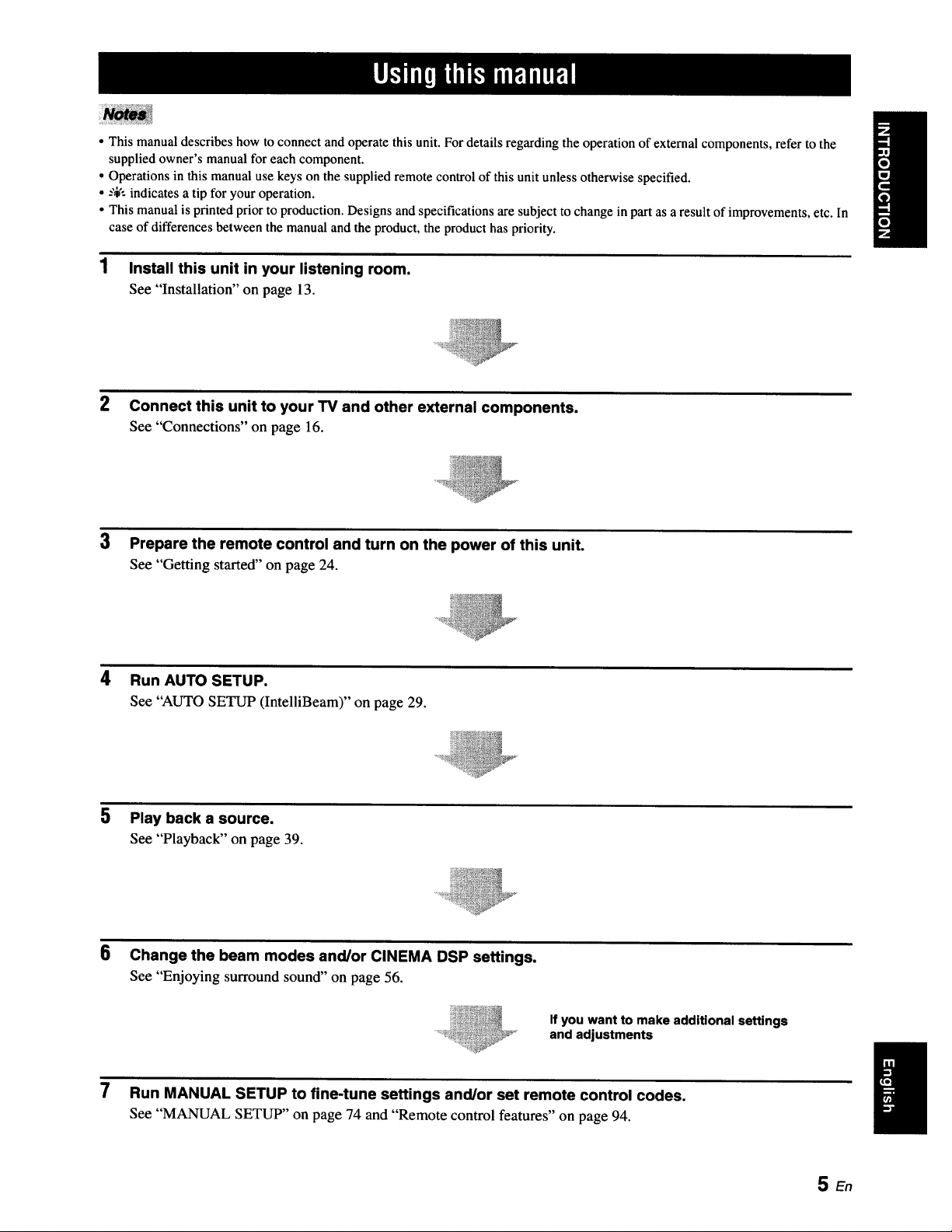
• This manual describes how to connect and operate this unit. For details regarding the operation of external components, refer to the
supplied owner's manual for each component.
• Operations in this manual use keys on the supplied remote control of this unit unless otherwise specified.
• --',i,':indicates a tip for your operation.
• This manual is printed prior to production. Designs and specifications are subject to change in part as a result of improvements, etc. In
case of differences between the manual and the product, the product has priority.
1 Install this unit in your listening room.
See "Installation" on page 13.
2 Connect this unit to your TV and other external components.
See "Connections" on page 16.
3 Prepare the remote control and turn on the power of this unit.
See "Getting started" on page 24.
4 Run AUTO SETUP.
See "AUTO SETUP (IntelliBeam)" on page 29.
5 Play back a source.
See "Playback" on page 39.
6
Change the beam modes and/or CINEMA DSP settings.
See "Enjoying surround sound" on page 56.
If you want to make additional settings
and adjustments
7 Run MANUAL SETUP to fine-tune settings and/or set remote control codes.
See "MANUAL SETUP" on page 74 and "Remote control features" on page 94.
SEn
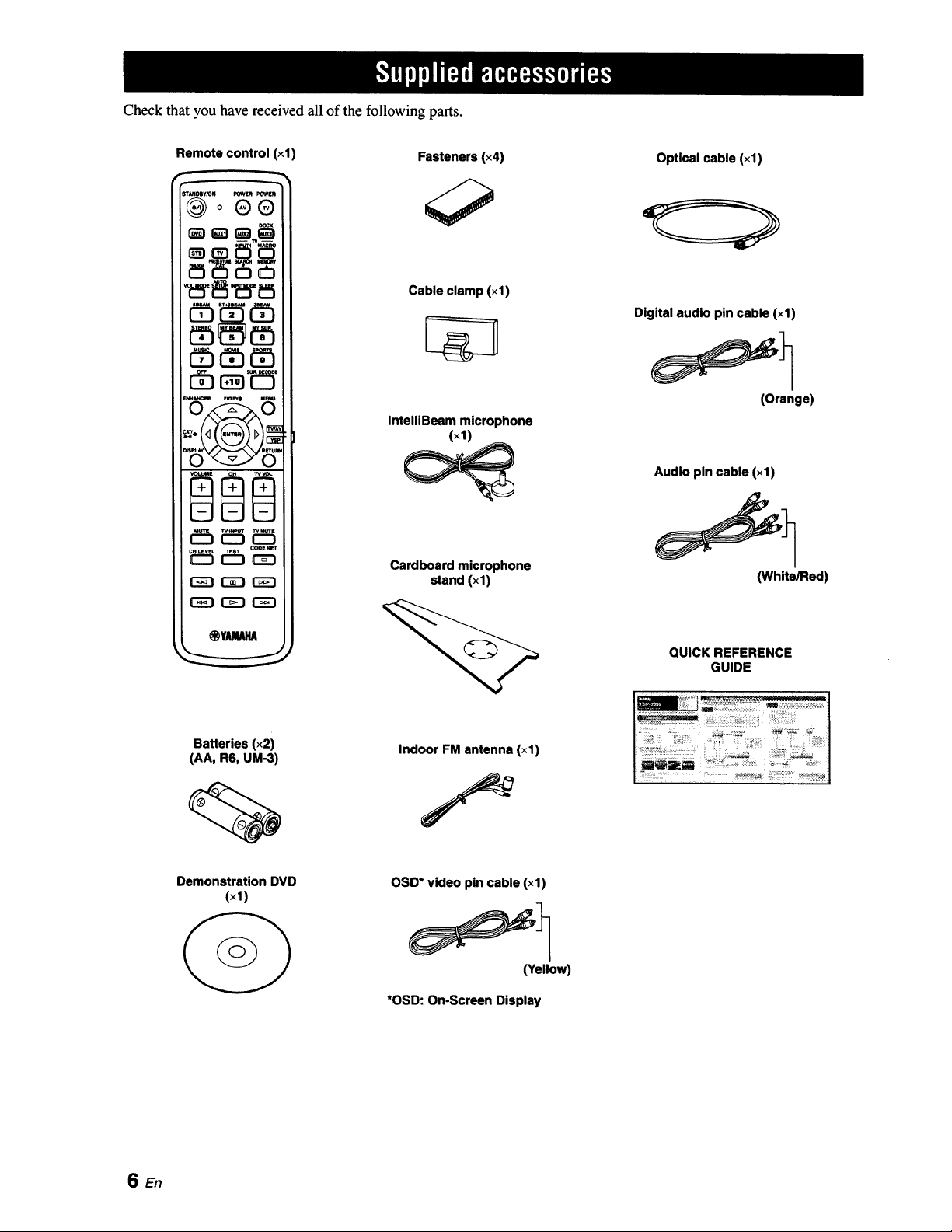
Check that you have received all of the following parts.
Remote control (xl)
®o®®
_ _5 cb_
r-_-i r-z-i r"_-i
Fasteners (×4)
Cable clamp (×1)
IntelllBeam microphone
(×1)
Cardboard microphone
stand (xl)
Optical cable (×1)
Digital audio pin cable (×1)
(Orange)
Audio pin cable (xl)
(White/Red)
QUICK REFERENCE
GUIDE
Batteries (x2)
(AA, R6, UM-3)
Indoor FM antenna (×1)
Demonstration DVD
(×1)
OSD* video pin cable (xl)
(Yellow)
*OSD: On-Screen Display
SEn
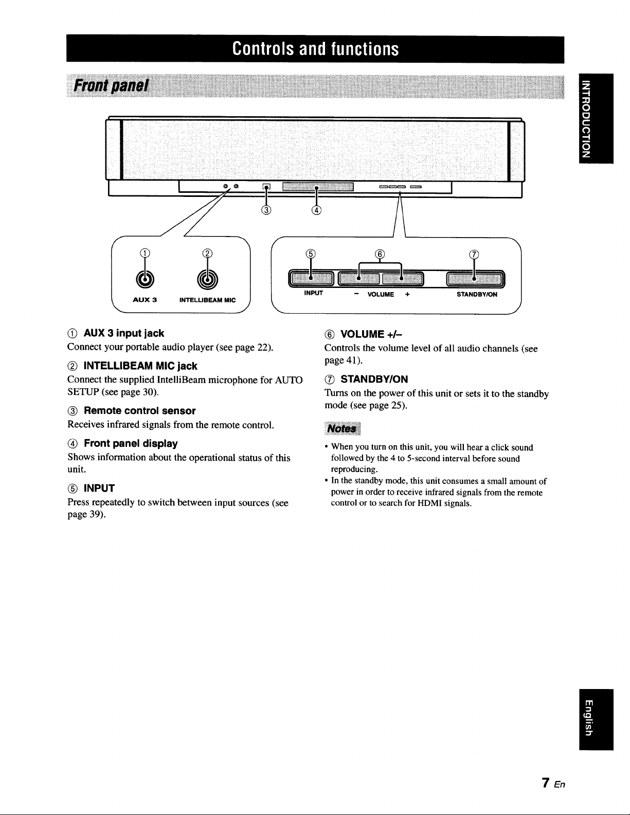
INPUT
0) AUX 3 input jack
Connect your portable audio player (see page 22).
(_ INTELLIBEAM MIC jack
Connect the supplied IntelliBeam microphone for AUTO
SETUP (see page 30).
(_ Remote control sensor
Receives infrared signals from the remote control.
(_ Front panel display
Shows information about the operational status of this
unit.
INPUT
Press repeatedly to switch between input sources (see
page 39).
VOLUME ÷ STANDBY/ON
1
_) VOLUME +/-
Controls the volume level of all audio channels (see
page 41).
O STAN DBYION
Turns on the power of this unit or sets it to the standby
mode (see page 25).
• When you turn on this unit, you will hear a click sound
followed by the 4 to 5-second interval before sound
reproducing.
• In the standby mode, this unit consumes a small amount of
power in order to receive infrared signals from the remote
control or to search for HDMI signals.
TEn
Ilwml_'TJ'Tll|°||'|f|Pif|ql(,
IIIU uln ;'Ill "-';U
IIIII IIIII lllll IIIII
III
lull IllU llUl ,,,U
/ill| .... , .....ll;ll uu| eenn
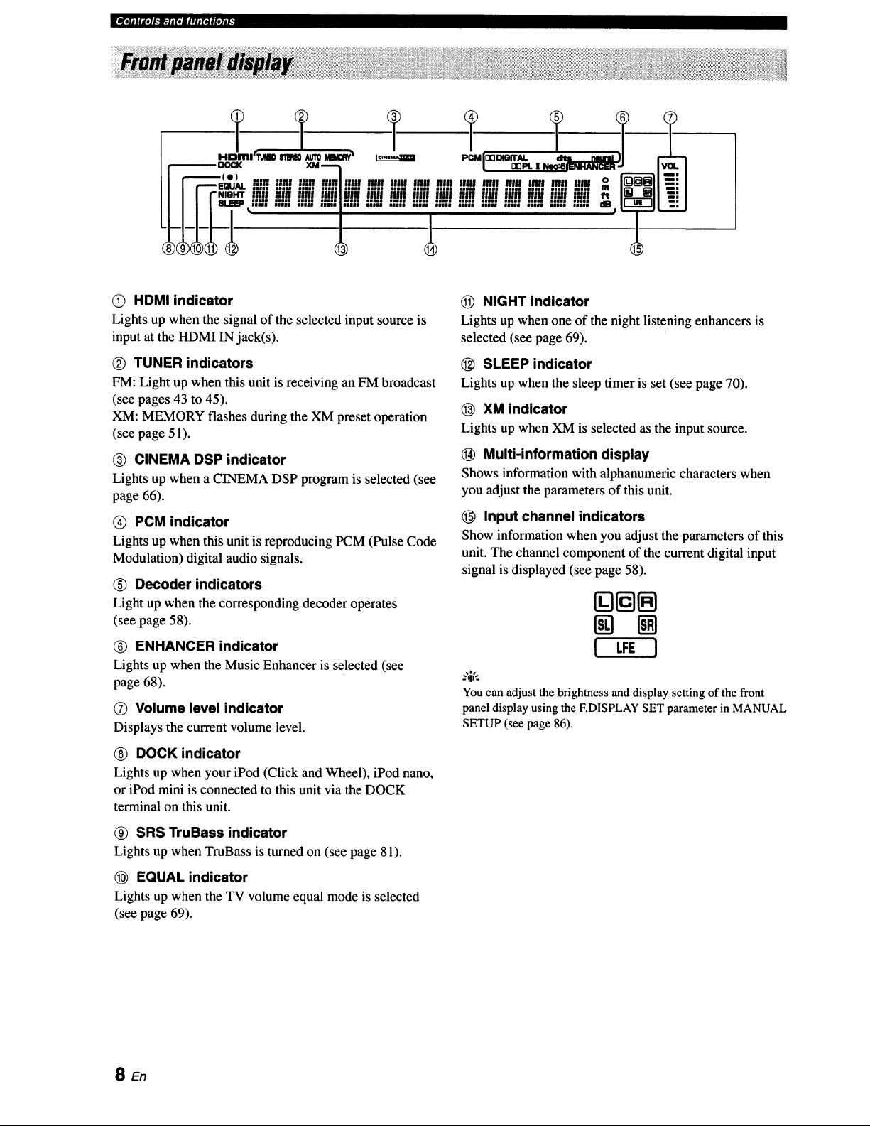
O HDMI indicator
Lights up when the signal of the selected input source is
input at the HDMI IN jack(s).
Q TUNER indicators
FM: Light up when this unit is receiving an FM broadcast
(see pages 43 to 45).
XM: MEMORY flashes during the XM preset operation
(see page 51).
CINEMA DSP indicator
Lights up when a CINEMA DSP program is selected (see
page 66).
Q PCM indicator
Lights up when this unit is reproducing PCM (Pulse Code
Modulation) digital audio signals.
(_) Decoder indicators
Light up when the corresponding decoder operates
(see page 58).
(_) ENHANCER indicator
Lights up when the Music Enhancer is selected (see
page 68).
O Volume level indicator
Displays the current volume level.
_) DOCK indicator
Lights up when your iPod (Click and Wheel), iPod nano,
or iPod mini is connected to this unit via the DOCK
terminal on this unit.
_) SRS TruBass indicator
Lights up when TruBass is turned on (see page 81).
EQUAL indicator
Lights up when the TV volume equal mode is selected
(see page 69).
NIGHT indicator
Lights up when one of the night listening enhancers is
selected (see page 69).
(_) SLEEP indicator
Lights up when the sleep timer is set (see page 70).
(_ XM indicator
Lights up when XM is selected as the input source.
(_ Multi-information display
Shows information with alphanumeric characters when
you adjust the parameters of this unit.
O Input channel indicators
Show information when you adjust the parameters of this
unit. The channel component of the current digital input
signal is displayed (see page 58).
[][][]
! LFE I
You can adjust the brightness and display setting of the front
panel display using the F.DISPLAY SET parameter in MANUAL
SETUP (see page 86).
SEn

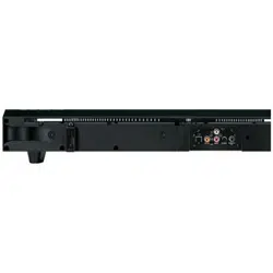
q_r_kla.llll*Jl#lJINelol#t_
(i) ANTENNA jack
Connect the FM antenna (see page 23).
(_) DOCK terminal
Connect the Yamaha iPod universal dock (such as YDS-
10, sold separately) (see page 53).
(_) AUX 1 AUDIO INPUT jacks
Connect an external component via an analog connection
(see page 20).
(_) TV/STB AUDIO INPUT jacks
Connect your TV, digital satellite tuner, or cable TV tuner
via an analog connection (see pages 21).
(_) VIDEO OUT jack
Connect to the video input jack of your TV via a
composite analog video connection to display the OSD of
this unit (see page 21).
® SUBWOOFER OUT jack
Connect your subwoofer (see page 22).
O STB VIDEO INPUT jacks
Connect a digital satellite tuner or a cable TV tuner via a
composite analog video connection (see pages 19).
® DVD COMPONENT VIDEO INPUT jacks
Connect aDVD player/recorder or an external component
via acomponentanalogvideo connection(seepages 19
and 20).
(_) AUX 2 COAXIAL DIGITAL INPUT jack
Connect an external component via a coaxial digital
connection(seepage20).
AUX 1 OPTICAL DIGITAL INPUT jack
Connect an external component via an optical digital
connection (see page 20).
Q TV/STB OPTICAL DIGITAL INPUT jack
Connect your TV, digital satellite tuner, or cable TV tuner
via an optical digital connection (see pages 19 and 21).
DVD COAXIAL DIGITAL INPUT jack
Connect your DVD player via a coaxial digital connection
(see page 19).
(_ XM antenna jack
Connect your XM Mini-Tuner Home Dock (sold
separately) (see page 47).
(_) IR IN terminal
This is a control expansion terminal for commercial use
only (see page 23).
STB HDMI IN jack
Connect your digital satellite tuner, cable TV tuner, digital
airwave tuner, or game console via an HDMI connection
(see page 18).
DVD HDMI IN jack
Connect your DVD player via an HDMI connection (see
page 18).
HDMI OUT jack
Connect to the HDMI input jack on your HDMI
component such as a TV or a projector connected to this
unit (see page 18 to 20).
(_ AC power supply cable
Connect to the AC wall outlet (see page 23).
9 En
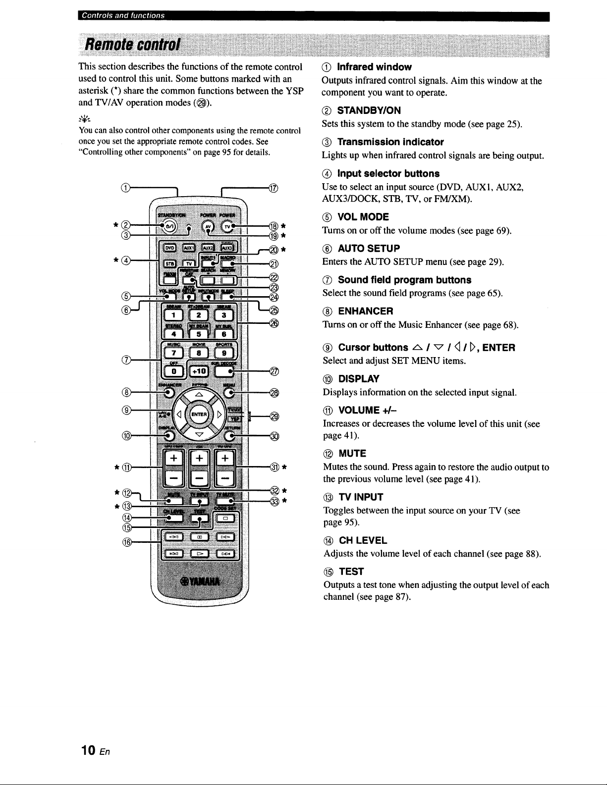
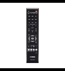
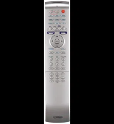
This section describes the functions of the remote control
used to control this unit. Some buttons marked with an
asterisk (*) share the common functions between the YSP
and TV/AV operation modes ((_).
_%'..
You can also control other components using the remote control
once you set the appropriate remote control codes. See
"Controlling other components" on page 95 for details.
@ @
® @,
@
®
@ Infrared window
Outputs infrared control signals. Aim this window at the
component you want to operate.
Q STANDBY/ON
Sets this system to the standby mode (see page 25).
@ Transmission indicator
Lights up when infrared control signals are being output.
(_) Input selector buttons
Use to select an input source (DVD, AUX1, AUX2,
AUX3/DOCK, STB, TV, or FM/XM).
O VOL MODE
Turns on or off the volume modes (see page 69).
® AUTO SETUP
Enters the AUTO SETUP menu (see page 29).
(_ Sound field program buttons
Select the sound field programs (see page 65).
(_) ENHANCER
Turns on or off the Music Enhancer (see page 68).
@ Cursor buttons -_- I _ I _ I D, ENTER
Select and adjust SET MENU items.
@ DISPLAY
Displays information on the selected input signal.
(_) VOLUME +/-
Increasesor decreases the volume level of this unit (see
page 41).
@ MUTE
Mutes the sound. Press again to restore the audio output to
the previous volume level (see page 41).
@ TV INPUT
Toggles between the input source on your TV (see
page 95).
CH LEVEL
Adjusts the volume level of each channel (see page 88).
TEST
Outputs a test tone when adjusting the output level of each
channel (see page 87).
10 En
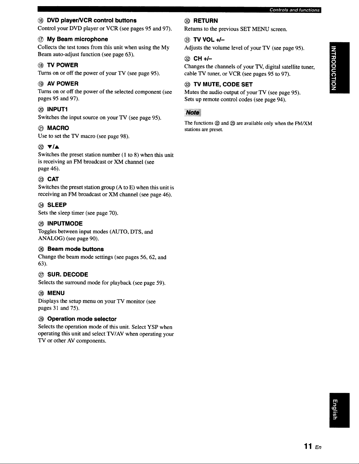
DVD player/VCR control buttons
Control your DVD player or VCR (see pages 95 and 97).
_) My Beam microphone
Collects the test tones from this unit when using the My
Beam auto-adjust function (see page 63).
(_ TV POWER
Turns on or off the power of your TV (see page 95).
AV POWER
Turns on or off the power of the selected component (see
pages 95 and 97).
INPUT1
Switches the input source on your TV (see page 95).
_) MACRO
Use to set the TV macro (see page 98).
VIA
Switches the preset station number (1 to 8) when this unit
is receiving an FM broadcast or XM channel (see
page 46).
@ CAT
Switches the preset station group (A to E) when this unit is
receiving an FM broadcast or XM channel (see page 46).
SLEEP
Sets the sleep timer (see page 70).
INPUTMODE
Toggles between input modes (AUTO, DTS, and
ANALOG) (see page 90).
Beam mode buttons
Change the beam mode settings (see pages 56, 62, and
63).
SUR. DECODE
Selects the surround mode for playback (see page 59).
MENU
Displays the setup menu on your TV monitor (see
pages 31 and 75).
Operation mode selector
Selects the operation mode of this unit. Select YSP when
operating this unit and select TV/AV when operating your
TV or other AV components.
,,llIIIIJ'e]l._]p;.llit||lll(ll|le]ll_
RETURN
Returns to the previous SET MENU screen.
TV VOL +/-
Adjusts the volume level of your TV (see page 95).
CH+I-
Changes the channels of your TV, digital satellite tuner,
cable TV tuner, or VCR (see pages 95 to 97).
TV MUTE, CODE SET
Mutes the audio output of your TV (see page 95).
Sets up remote control codes (see page 94).
The functions _ and _ are available only when the FM/XM
stations are preset.
11 En
E_r;11_I.'_.fip_-Iaqf|qlt'
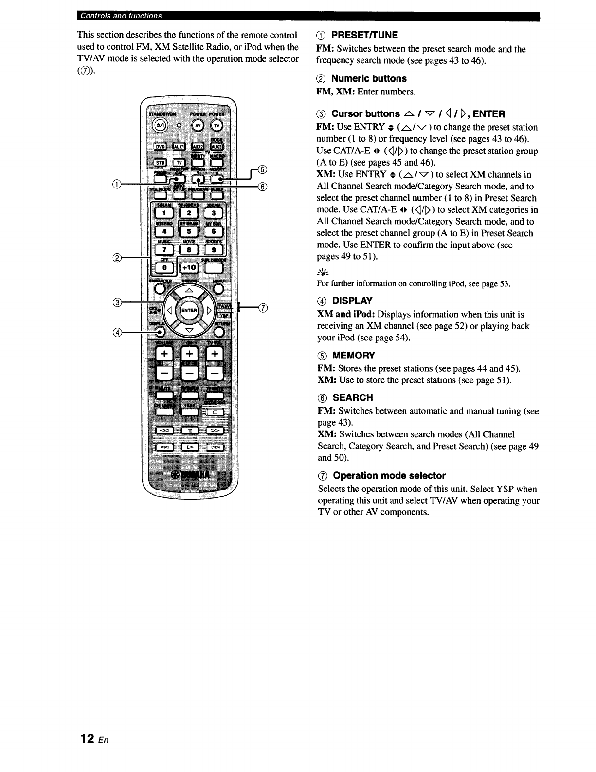
This section describes the functions of the remote control
used to control FM, XM Satellite Radio, or iPod when the
TV/AV mode is selected with the operation mode selector
®
®
Q PRESET/TUNE
FM: Switches between the preset search mode and the
frequency search mode (see pages 43 to 46).
(_ Numeric buttons
FM, XM: Enter numbers.
® Cursor buttons _ I _ I _ I _, ENTER
FM: Use ENTRY # (/x/_) to change the preset station
number (1 to 8) or frequency level (see pages 43 to 46).
Use CAT/A-E o (<_/_>)to change the preset station group
(A to E) (see pages 45 and 46).
XM: Use ENTRY € (A/_) to select XM channels in
All Channel Search mode/Category Search mode, and to
select the preset channel number (1 to 8) in Preset Search
mode. Use CAT/A-E o (<_/_>)to select XM categories in
All Channel Search mode/Category Search mode, and to
select the preset channel group (A to E) in Preset Search
mode. Use ENTER to confirm the input above (see
pages 49 to 51).
:,;€.
For further information on controlling iPod, see page 53.
@ DISPLAY
XM and iPod: Displays information when this unit is
receiving an XM channel (see page 52) or playing back
your iPod (see page 54).
(_) MEMORY
FM: Stores the preset stations (see pages 44 and 45).
XM: Use to store the preset stations (see page 51).
® SEARCH
FM: Switches between automatic and manual tuning (see
page 43).
XM: Switches between search modes (All Channel
Search, Category Search, and Preset Search) (see page 49
and 50).
O Operation mode selector
Selects the operation mode of this unit. Select YSP when
operating this unit and select TV/AV when operating your
TV or other AV components.
12 En
This section describes a suitable installation location to install this unit using a metal wall bracket, a rack or a stand.
Depending on your installation environment, connections with external components can be done before installing this
unit. We recommend that you temporarily place and arrange all components, including this unit, in order to decide which
procedure should come first. Especially when you make a connection over HDMI, we recommend that you make a
connection first before installation (see page 18).
This unit creates surround sound by reflecting projected
sound beams off the walls of your listening room. The
surround sound effects produced by this unit may not be
sufficient when this unit is installed in the following
locations.
• Rooms with walls inadequate for reflecting sound
beams
• Rooms with acoustically absorbent walls
• Rooms with measurements outside the following
range: W (3 to 7 m (10 to 23 ft)) x H (2 to 3.5 m (7 to
11.5 ft)) x D (3 to 7 m (10 to 23 ft))
• Rooms with less than 1.8 m (6 ft) from the listening
position to this unit
• Rooms where objects such as furniture are likely to
obstruct the path of sound beams
• Rooms where the listening position is close to the walls
• Rooms where the listening position is not in front of
this unit
• You can enjoy surround sound by selecting My Surround (see
page 57) as the beam mode even if your listening room may not
fulfill the above conditions (except when the listening position
is not directly facing toward the front of this unit).
• You can also enjoy surround sound by selecting 2-channel or 5-
channel stereo playback (see page 62) or My Beam (see
page 63) as the beam mode even if your listening room may not
fulfill the above conditions.
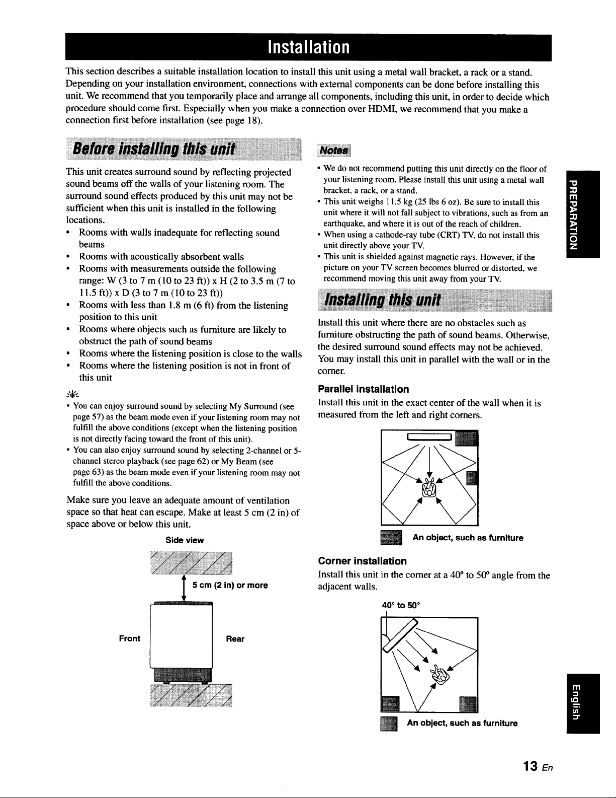
Make sure you leave an adequate amount of ventilation
space so that heat can escape. Make at least 5 cm (2 in) of
space above or below this unit.
Side view
5 cm (2 in) or more
Front Rear
• We do not recommend putting this unit directly on the floor of
your listening room. Please install this unit using a metal wall
bracket, a rack, or a stand.
• This unit weighs 11.5 kg (25 lbs 6 oz). Be sure to install this
unit where it will not fall subject to vibrations, such as from an
earthquake, and where it is out of the reach of children.
• When using a cathode-ray tube (CRT) TV, do not install this
unit directly above your TV.
• This unit is shielded against magnetic rays. However, if the
picture on your TV screen becomes blurred or distorted, we
recommend moving this unit away from your TV.
Install this unit where there are no obstacles such as
furniture obstructing the path of sound beams. Otherwise,
the desired surround sound effects may not be achieved.
You may install this unit in parallel with the wall or in the
corner.
Parallel installation
Install this unit in the exact center of the wall when it is
measured from the left and right corners.
l
An object, such as furniture
Corner installation
Install this unit in the corner at a 40 ° to 50 ° angle from the
adjacent walls.
40 ° to 50°
m
An object, such as furniture
13 En
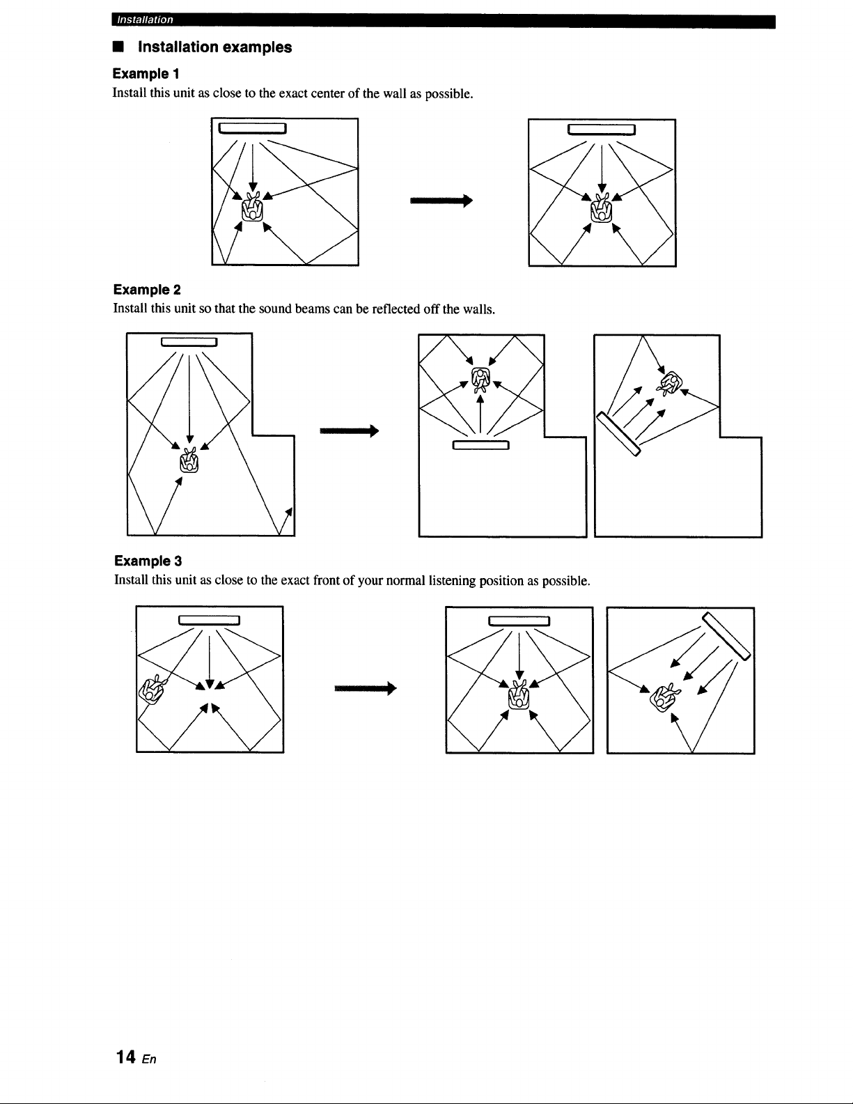
• Installation examples
Example 1
Install this unit as close to the exact center of the wall as possible.
[ I
I
I I
I
Example 2
Install this unit so that the sound beams can be reflected off the walls.
I !
/
/\
I !
Example 3
Install this unit as close to the exact front of your normal listening position as possible.
! I
I
14_
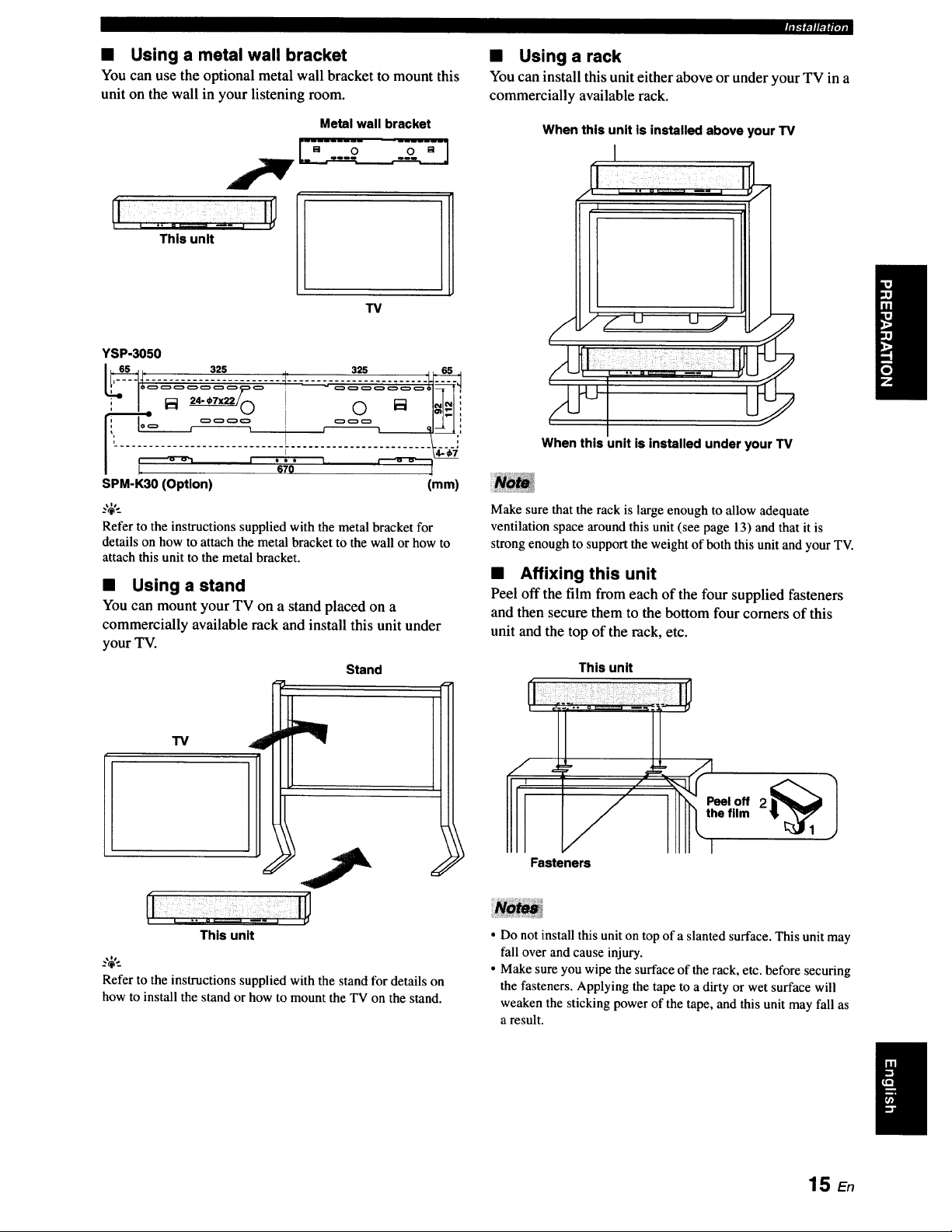
• Using a metal wall bracket
You can use the optional metal wall bracket to mount this
unit on the wall in your listening room.
This unit
Metal wall bracket
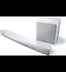
TV
YSP-3050
r_lffll_fpjj
• Using a rack
You can install this unit either above or under your TV in a
commercially available rack.
When this unit is installed above your TV
I
When this unit is installed under your TV
SPM-K30 (Option) (mm)
_%'._
Refer to the instructions supplied with the metal bracket for
details on how to attach the metal bracket to the wall or how to
attach this unit to the metal bracket.
• Using a stand
You can mount your TV on a stand placed on a
commercially available rack and install this unit under
your TV.
"13/
i
Stand
Make sure that the rack is large enough to allow adequate
ventilation space around this unit (see page 13) and that it is
strong enough to support the weight of both this unit and your TV.
• Affixing this unit
Peel off the film from each of the four supplied fasteners
and then secure them to the bottom four comers of this
unit and the top of the rack, etc.
This unit
Fasteners
This unit
..,;,..
Refer to the instructions supplied with the stand for details on
how to install the stand or how to mount the TV on the stand.
• Do not install this unit on top of a slanted surface. This unit may
fall over and cause injury.
• Make sure you wipe the surface of the rack, etc. before securing
the fasteners. Applying the tape to a dirty or wet surface will
weaken the sticking power of the tape, and this unit may fall as
a result.
15 En
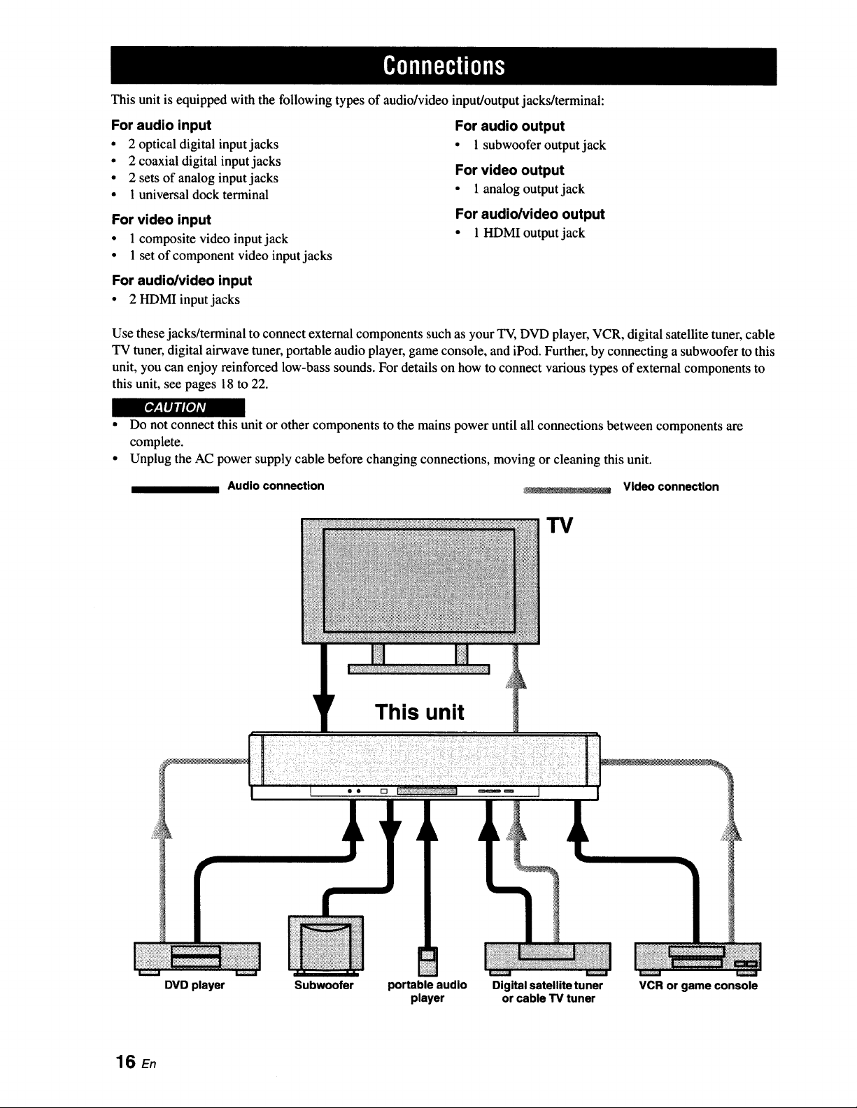
This unit is equipped with the following types of audio/video input/output jacks/terminal:
For audio input
• 2 optical digital input jacks
• 2 coaxial digital input jacks
• 2 sets of analog input jacks
• 1 universal dock terminal
For video input
• 1 composite video input jack
• 1 set of component video input jacks
For audio/video input
• 2 HDMI input jacks
For audio output
• 1 subwoofer output jack
For video output
• 1 analog output jack
For audio/video output
• 1 HDMIoutputjack
Use these jacks/terminal to connect external components such as your TV, DVD player, VCR, digital satellite tuner, cable
TV tuner, digital airwave tuner, portable audio player, game console, and iPod. Further, by connecting a subwoofer to this
unit, you can enjoy reinforced low-bass sounds. For details on how to connect various types of external components to
this unit, see pages 18 to 22.
r_
• Do not connect this unit or other components to the mains power until all connections between components are
complete.
• Unplug the AC power supply cable before changing connections, moving or cleaning this unit.
Audio connection
_. - _-L.... : _ Video connection
TV
This unit
• • rt
DVD player Subwoofer portable audio
player
Digital satellite tuner
or cable TV tuner
VCR or game console
16 En
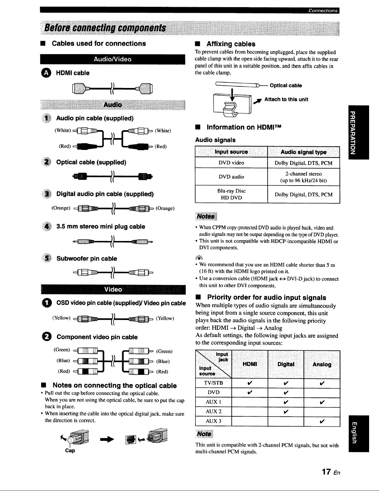
• Cables used for connections
O HDMI cable
Audio pin cable (supplied)
(Red) (Red)
Optical cable (supplied)
Digital audio pin cable (supplied)
(Orange) l/ (Orange)
3.5 mm stereo mini plug cable
Subwoofer pin cable
O pin (supplied)/Video pin cable
OSD video
cable
(Yellow) (Yellow)
Component video pin cable
(Green) __ (Green)
(Blue) (Blue)
(Red) (Red)
• Notes on connecting the optical cable
• Pull out the cap before connecting the optical cable.
When you are not using the optical cable, be sure to put the cap
back in place.
• When inserting the cable into the optical digital jack, make sure
the direction is correct.
• Affixing cables
To prevent cables from becoming unplugged, place the supplied
cable clamp with the open side facing upward, attach it to the rear
panel of this unit in a suitable position, and then affix cables in
the cable clamp.
Optical cable
,_IF Attach to this unit
• Information on HDMI TM
Audio signals
DVD video Dolby Digital, DTS, PCM
2-channel stereo
DVD audio
(up to 96 kHz/24 bit)
Blu-ray Disc
HD DVD Dolby Digital, DTS, PCM
• When CPPM copy-protected DVD audio is played back, video and
audio signals may not be output depending on the type of DVDplayer.
• This unit is not compatible with HDCP-incompatible HDMI or
DVI components.
.%,..
• We recommend that you use an HDMI cable shorter than 5 m
(16 ft) with the HDMI logo printed on it.
• Use a conversion cable (HDMI jack +-_DVI-D jack) to connect
this unit to other DVI components.
• Priority order for audio input signals
When multiple types of audio signals are simultaneously
being input from a single source component, this unit
plays back the audio signals in the following priority
order: HDMI _ Digital --_ Analog
As default settings, the following input jacks are assigned
to the corresponding input sources:
TVISTB
DVD
AUX 1
AUX 2
AUX 3
i/ t/
t/ t/
it
t,t
t/
l/
t/
Cap
This unit is compatible with 2-channel PCM signals, but not with
multi-channel PCM signals.
17 E,
_[D[olili['..IOll[elig
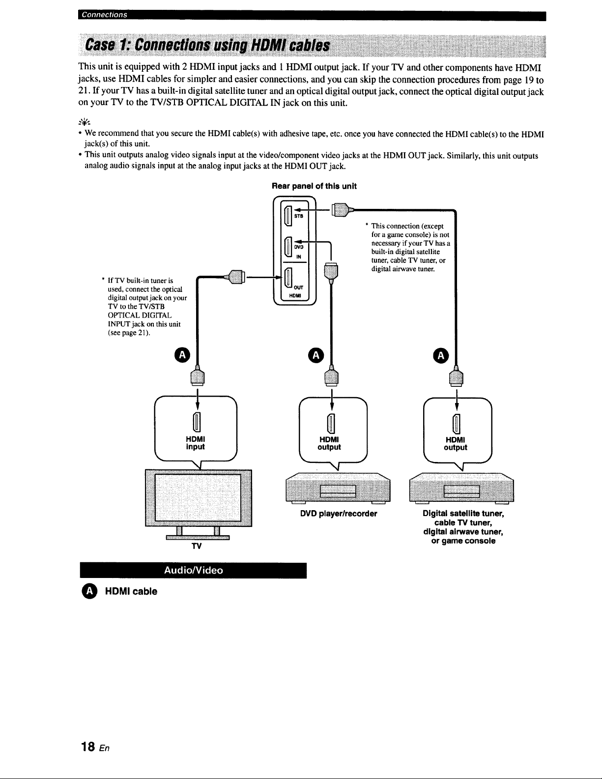
This unit is equipped with 2 HDMI input jacks and 1 HDMI output jack. If your TV and other components have HDMI
jacks, use HDMI cables for simpler and easier connections, and you can skip the connection procedures from page 19 to
21. If your TV has a built-in digital satellite tuner and an optical digital output jack, connect the optical digital output jack
on your TV to the TV/STB OPTICAL DIGITAL IN jack on this unit.
• We recommend that you secure the HDMI cable(s) with adhesive tape,etc. onceyou haveconnectedthe HDMIcable(s) to the HDMI
jack(s) of this unit.
• This unit outputs analog video signalsinput at the video/componentvideo jacks at the HDMIOUT jack. Similarly,this unit outputs
analogaudio signals input at the analog inputjacks at the HDMIOUT jack.
* IfTV built-in tuner is
used, connect the optical
digital output jack on your
TV to the TV/STB
OPTICAL DIGITAL
INPLrr jack on this unit
(see page 21).
O
HDMI
input
Rear panel of this unit
0
HDMI
output
* This connection (except
for a game console) is not
necessary if your TV has a
built-in digital satellite
tuner, cable TV tuner, or
digital airwave tuner.
DVD playerlrecorder
O
HDMI
output
",4
TV
Digital satellite tuner,
cable TV tuner,
digital airwave tuner,
or game console
O HDMI cable
18 En
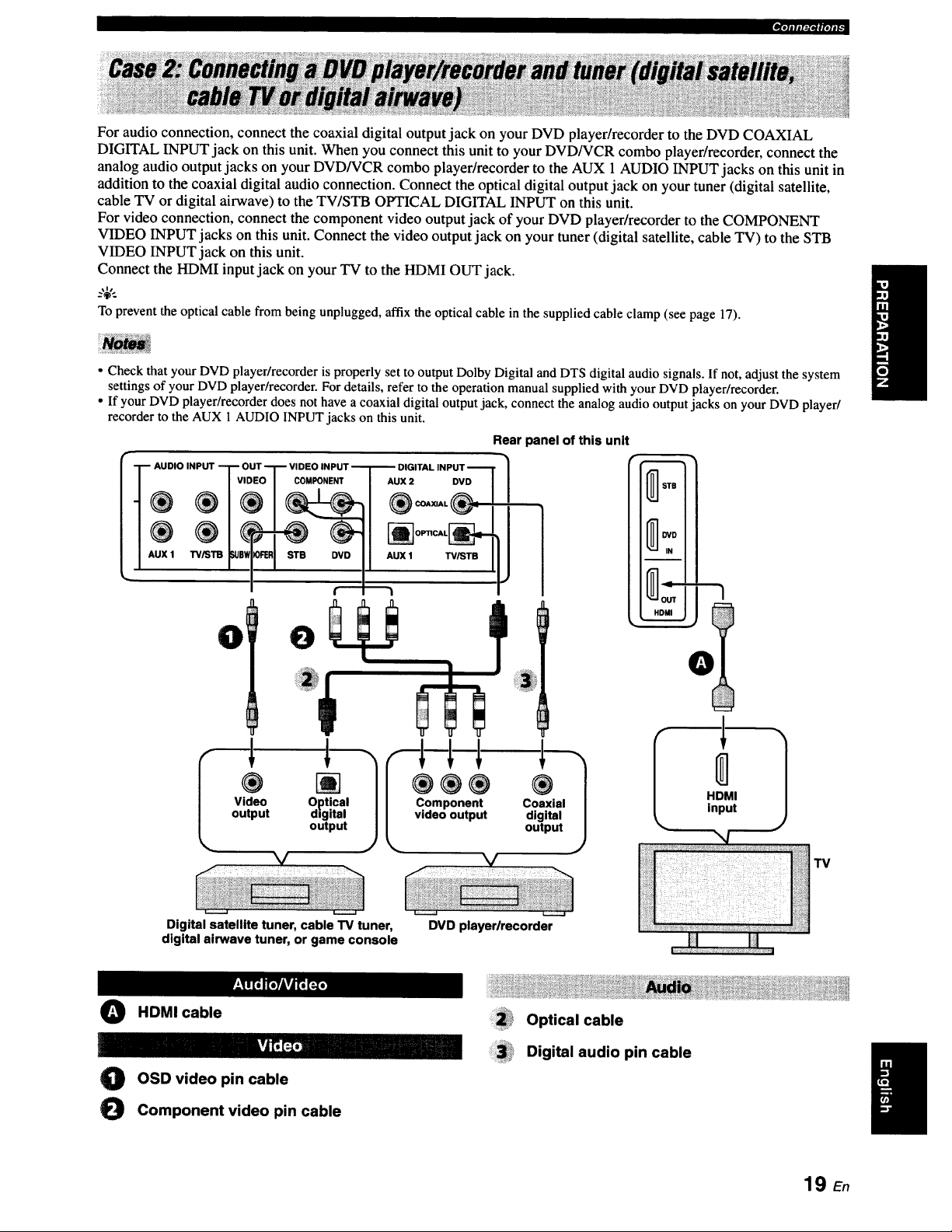
_.]alJl:1_#[Olt_
For audio connection, connect the coaxial digital output jack on your DVD player/recorder to the DVD COAXIAL
DIGITAL INPUT jack on this unit. When you connect this unit to your DVD/VCR combo player/recorder, connect the
analog audio output jacks on your DVD/VCR combo player/recorder to the AUX 1 AUDIO INPUT jacks on this unit in
addition to the coaxial digital audio connection. Connect the optical digital output jack on your tuner (digital satellite,
cable TV or digital airwave) to the TV/STB OPTICAL DIGITAL INPUT on this unit.
For video connection, connect the component video output jack of your DVD player/recorder to the COMPONENT
VIDEO INPUT jacks on this unit. Connect the video output jack on your tuner (digital satellite, cable TV) to the STB
VIDEO INPUT jack on this unit.
Connect the HDMI input jack on your TV to the HDMI OUT jack.
_%,..
To prevent the optical cable from being unplugged, affix the optical cable in the supplied cable clamp (see page 17).
• Check that your DVD player/recorder is properly set to output Dolby Digital and DTS digital audio signals. If not, adjust the system
settings of your DVD player/recorder. For details, refer to the operation manual supplied with your DVD player/recorder.
• If your DVD player/recorder does not have a coaxial digital output jack, connect the analog audio output jacks on your DVD player/
recorder to the AUX 1 AUDIO INPUT jacks on this unit.
AUDIO INPUT T O
®
AUX 1 TV,_T13 _e_
DVD
TV/STB
0 0
Rear panel of this unit
0
Video Optical
output digital
output
L C_emoP°untepnutt
'1
®
Coaxial
digital
output
Digital satellite tuner, cable TV tuner,
digital airwave tuner, or game console
DVD playerlrecorder
O HDMI cable
O OSD video pin cable
O Component video pin cable
Optical cable
Digital audio pin cable
19 E.
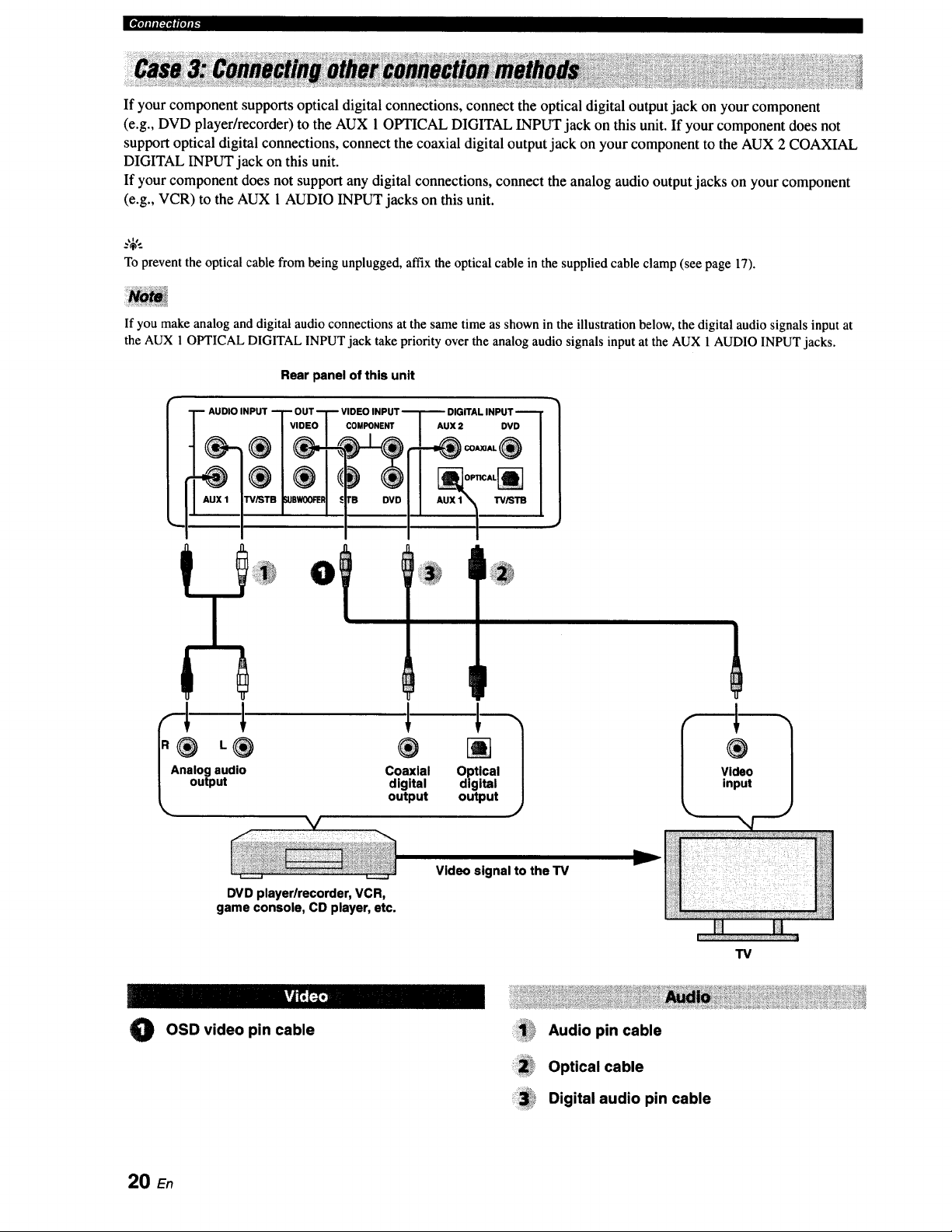
|¶'ililI:PII|'tlI"
If your component supports optical digital connections, connect the optical digital output jack on your component
(e.g., DVD player/recorder) to the AUX 1 OPTICAL DIGITAL INPUT jack on this unit. If your component does not
support optical digital connections, connect the coaxial digital output jack on your component to the AUX 2 COAXIAL
DIGITAL INPUT jack on this unit.
If your component does not support any digital connections, connect the analog audio output jacks on your component
(e.g., VCR) to the AUX 1 AUDIO INPUT jacks on this unit.
Toprevent the optical cable from beingunplugged, affixthe optical cable in the suppliedcable clamp (see page 17).
If you make analog and digital audio connections at the same time as shown in the illustration below, the digital audio signals input at
the AUX 1 OPTICAL DIGITAL INPUT jack take priority over the analog audio signals input at the AUX 1 AUDIO INPUT jacks.
Rear panel of this unit
L® ®
I Analog audio Coaxial
digital
_, output output
DIGITAL INPUT
AUX 2 DVD
IP
[]
Optical
digital
output
f
®
Video
input
DVD player/recorder, VCR,
game console, CD player, etc.
Video signal to the TV
TV
kvJt';_
0
OSD video pin cable
ii!!!!i!_i!_Audiopincable
:i:ii!i!_,Optical cable
_3_i* Digital audio pin cable
20 En
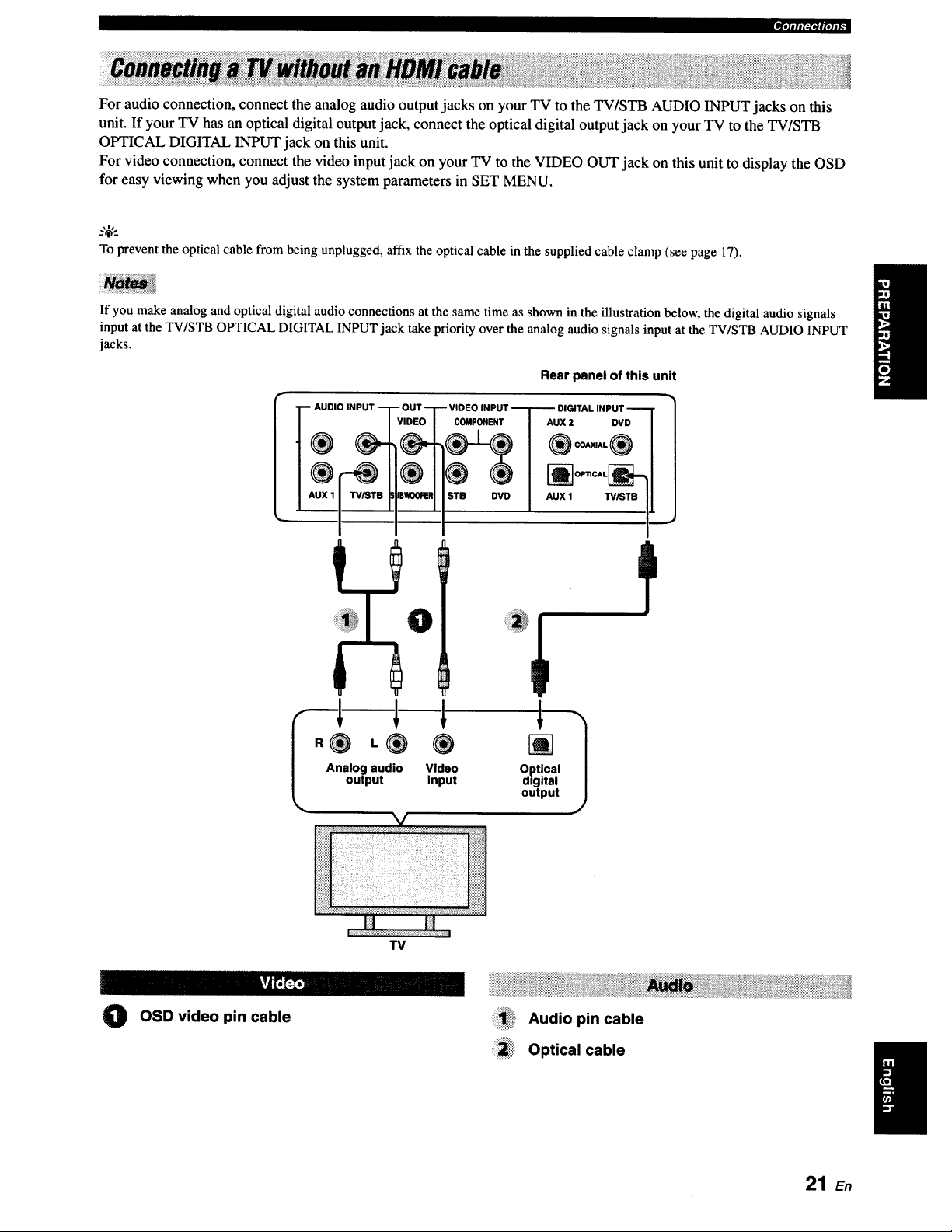
_,1-J_,VfpJiF
For audio connection, connect the analog audio output jacks on your TV to the TV/STB AUDIO INPUT jacks on this
unit. If your TV has an optical digital output jack, connect the optical digital output jack on your TV to the TV/STB
OPTICAL DIGITAL INPUT jack on this unit.
For video connection, connect the video input jack on your TV to the VIDEO OUT jack on this unit to display the OSD
for easy viewing when you adjust the system parameters in SET MENU.
.%',.
To prevent the optical cable from being unplugged, affix the optical cable in the supplied cable clamp (see page 17).
If you make analog and optical digital audio connections at the same time as shown in the illustration below, the digital audio signals
input at the TV/STB OPTICAL DIGITAL INPUT jack take priority over the analog audio signals input at the TV/STB AUDIO INPUT
jacks.
Rear panel of this unit
AUDIO INPUT
COMPONENT
STB DVD
- u x'7
_ OPTICAL_
AUX 1 W/STB I,
Analog audio Video Optical
output input digital
output
1
TV
O OSD video pin cable Audio pin cable
Optical cable
21 E.
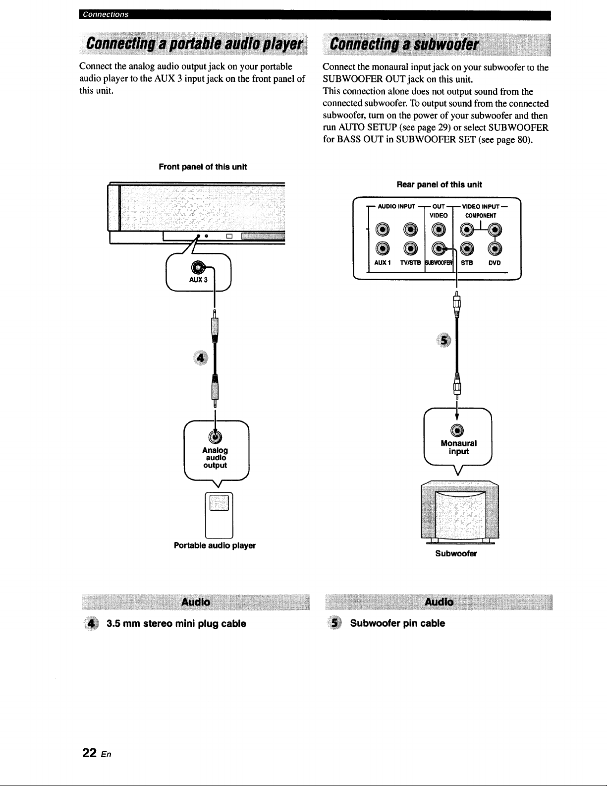
J[IV[I]IIII_I_|(ll|[_
Connect the analog audio output jack on your portable
audio player to the AUX 3 input jack on the front panel of
this unit.
Front panel of this unit
I jp o [] I:++++++;+++++,%_+++++?:_++
r/+
Connect the monaural input jack on your subwoofer to the
SUBWOOFER OUT jack on this unit.
This connection alone does not output sound from the
connected subwoofer. To output sound from the connected
subwoofer, turn on the power of your subwoofer and then
run AUTO SETUP (see page 29) or select SUBWOOFER
for BASS OUT in SUBWOOFER SET (see page 80).
Rear panel of this unit
-+D,OINP+T?S°
AUX 1 TViST WOOFEI_
-- VIDEO INPUT --
COMPONENT
STB DVD
Portable audio player
3.5 mm stereo mini plug cable
Subwoofer
Subwoofer pin cable
22 En
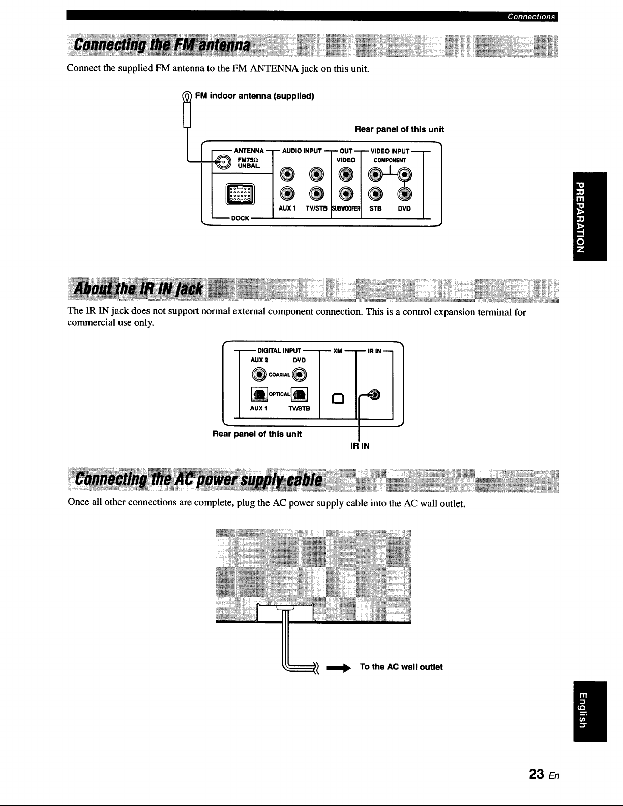
Connect the supplied FM antenna to the FM ANTENNA jack on this unit.
_'*itl#l:l*lglolll.
FM indoor antenna (supplied)
Rear panel of this unit
I r F'_--_ ANTENNA I_ AUDIO INPUT "-1" OUT "_ VIDEO INPUT "_[ _
It
II Q/® ®/®1® ®1
I / I,UXl _.pw®_ I s_e ovo/
_ DOCK _ t e l
The IR IN jack does not support normal external component connection. This is a control expansion terminal for
commercial use only.
I --]'--" DIGITAL INPUT "--T-- XM --T
I Aux= ovo I /
I ®c-_®I |
I "ux' _'°1 /
Rear panel of this unit
IR IN
IR IN 1
Once all other connections are complete, plug the AC power supply cable into the AC wall outlet.
To the AC wall outlet
23 En
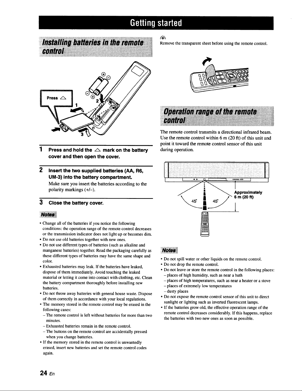
Remove the transparent sheet before using the remote control.
2
Press and hold the /_ mark on the battery
cover and then open the coven
Insert the two supplied batteries (AA, R6,
UM-3) into the battery compartment.
Make sure you insert the batteries according to the
polarity markings (+/-).
3 Close the battery cover.
• Change all of the batteries if you notice the following
conditions: the operation range of the remote control decreases
or the transmission indicator does not light up or becomes dim.
• Do not use old batteries together with new ones.
• Do not use different types of batteries (such as alkaline and
manganese batteries) together. Read the packaging carefully as
these different types of batteries may have the same shape and
color.
• Exhausted batteries may leak. If the batteries have leaked,
dispose of them immediately. Avoid touching the leaked
material or letting it come into contact with clothing, etc. Clean
the battery compartment thoroughly before installing new
batteries.
• Do not throw away batteries with general house waste. Dispose
of them correctly in accordance with your local regulations.
• The memory stored in the remote control may be erased in the
following cases:
- The remote control is left without batteries for more than two
minutes.
- Exhausted batteries remain in the remote control.
- The buttons on the remote control are accidentally pressed
when you change batteries.
• If the memory stored in the remote control is unwantedly
erased, insert new batteries and set the remote control codes
again.
The remote control transmits a directional infrared beam.
Use the remote control within 6 m (20 ft) of this unit and
point it toward the remote control sensor of this unit
during operation.
l
• Do not spill water or other liquids on the remote control.
• Do not drop the remote control.
• Do not leave or store the remote control in the following places:
- places of high humidity, such as near a bath
- places of high temperatures, such as near a heater or a stove
- places of extremely low temperatures
- dusty places
• Do not expose the remote control sensor of this unit to direct
sunlight or lighting such as inverted fluorescent lamps.
• If the batteries grow old, the effective operation range of the
remote control decreases considerably. If this happens, replace
the batteries with two new ones as soon as possible.
24 En
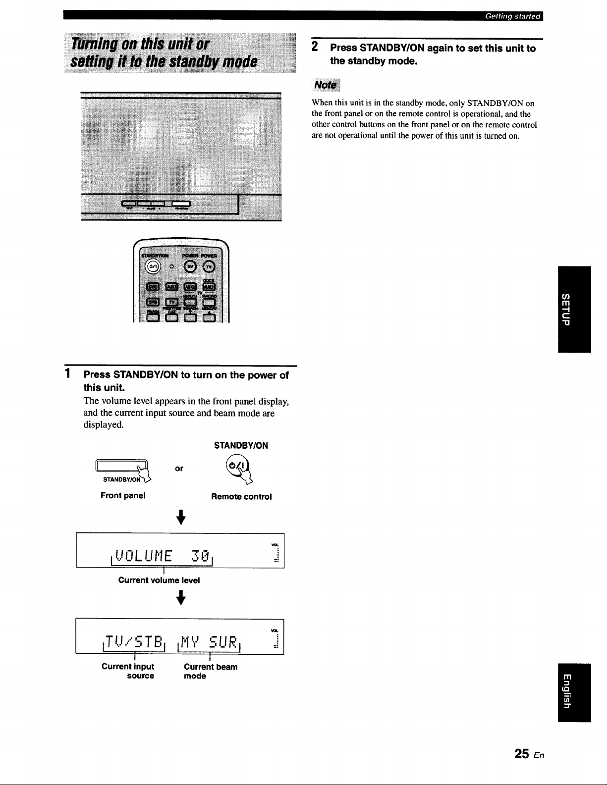
2 Press STANDBY/ON again to set this unit to
the standby mode.
When this unit is in the standby mode, only STANDBY/ON on
the front panel or on the remote control is operational, and the
other control buttons on the front panel or on the remote control
are not operational until the power of this unit is turned on.
Press STANDBY/ON to turn on the power of
this unit.
The volume level appears in the front panel display,
and the current input source and beam mode are
displayed.
I
STANDBY/ON
[[ STANDBY/ON_ or
Front panel Remote control
+
IUOLUr'IE 30 I
I
Current volume level
+
_TL._.."STBjtH'.,.' fUR i
I 1
Current input Current beam
source mode
25 En
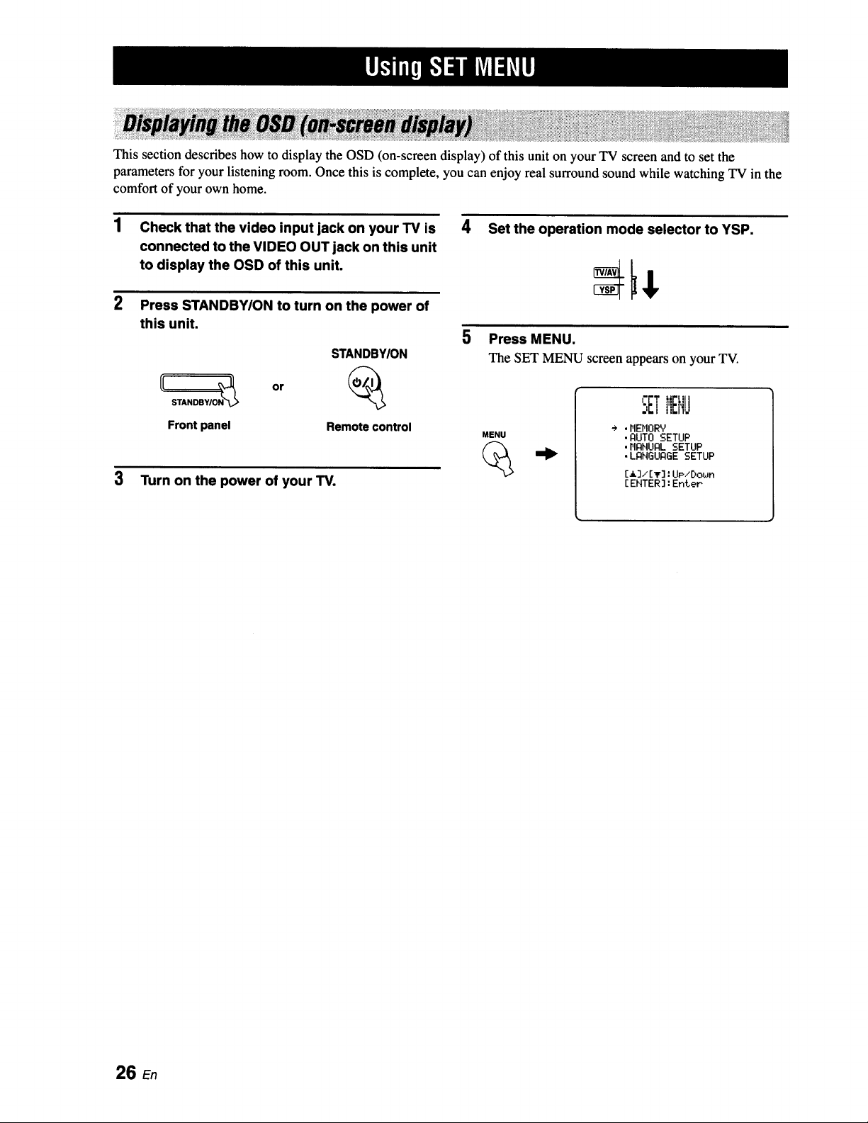
This section describes how to display the OSD (on-screen display) of this unit on your TV screen and to set the
parameters for your listening room. Once this is complete, you can enjoy real surround sound while watching TV in the
comfort of your own home.
1 Check that the video input jack on your TV is 4
connected to the VIDEO OUT jack on this unit
to display the OSD of this unit.
2 Press STANDBWON to turn on the power of
this unit.
STANDBYION
Set the operation mode selector to YSP.
5 Press MENU.
The SET MENU screen appears on your TV.
Front panel Remote control
MENU
3 Turn on the power of your TV.
SETMENU
÷ .HEHORY
• AUTO SETUP
,MANUAL SETUP
• LANGUAGE SETUP
[13/[lr]: UP/E)obJn
[ ENTER] : Enter
26 En
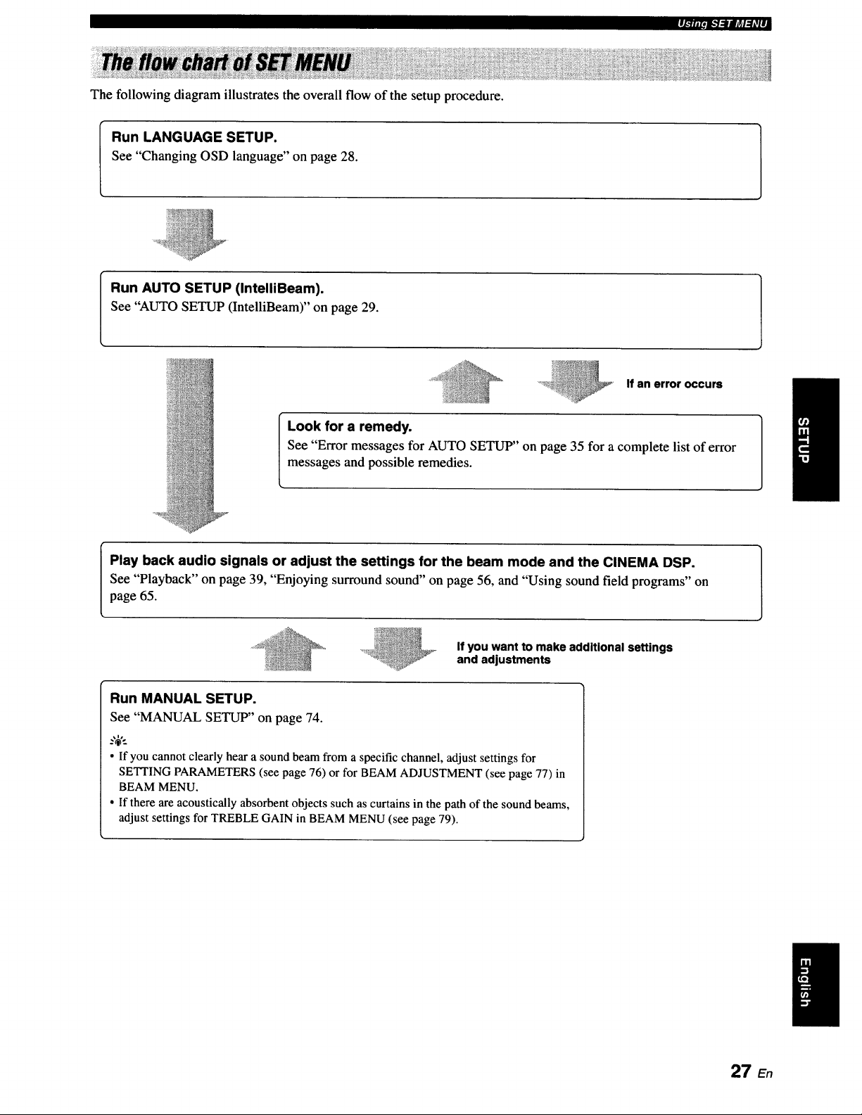
The following diagram illustrates the overall flow of the setup procedure.
pi.711P_.*l:lllArd:hVll
Run LANGUAGE SETUP.
See "Changing OSD language" on page 28.
Run AUTO SETUP (IntelliBeam).
See "AUTO SETUP (IntelliBeam)" on page 29.
If an error occurs
Look for a remedy.
See "Error messages for AUTO SETUP" on page 35 for a complete list of error
messages and possible remedies.
Play back audio signals or adjust the settings for the beam mode and the CINEMA DSP.
See "Playback" on page 39, "Enjoying surround sound" on page 56, and "Using sound field programs" on
page 65.
If you want to make additional settings
and adjustments
Run MANUAL SETUP.
See "MANUAL SETUP" on page 74.
• If you cannot clearly hear a sound beam from a specific channel, adjust settings for
SETTING PARAMETERS (see page 76) or for BEAM ADJUSTMENT (see page 77) in
BEAM MENU.
• If there are acoustically absorbent objects such as curtains in the path of the sound beams,
adjust settings for TREBLE GAIN in BEAM MENU (see page 79).
27 En
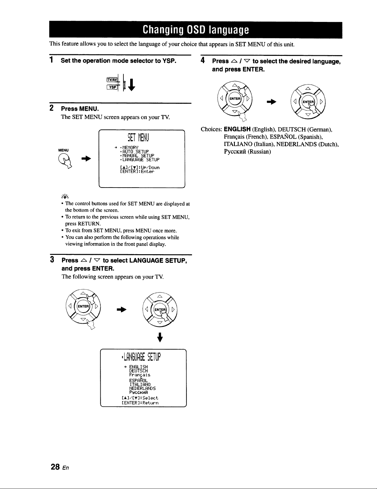
This feature allows you to select the language of your choice that appears in SET MENU of this unit.
1 Set the operation mode selector to YSP.
2
Press MENU.
The SET MENU screen appears on your TV.
MENU
SETMENU
÷ ,HEMORV
,AUTO SETUP
.MANUAL SETUP
,LANGUAGE SETUP
[_] / [T] : UP,'Dot,Jn
[ENTER ]: Enter
4 Press ,_ / _ to select the desired language,
and press ENTER.
Choices: ENGLISH (English), DEUTSCH (German),
Franqais (French), ESPAlqOL (Spanish),
ITALIANO (Italian), NEDERLANDS (Dutch),
PyccKnfi (Russian)
3
• The control buttons used for SET MENU are displayed at
the bottom of the screen.
• To return to the previousscreen whileusing SETMENU,
press RETURN.
• To exit from SET MENU,press MENUonce more.
• Youcan also perform the followingoperations while
viewinginformation in thefront panel display.
Press /'- / _ to select LANGUAGE SETUP,
and press ENTER.
The following screen appears on your TV.
%. ,'
,LAI,IGI.IAGESETUP
÷ EHGLISH
DEUTSCH
Frangais
ESPA_OL
ITALIAHO
HEDERLAHDS
P_CCKHR
[_]/[T]:Select
[EHTER]:Return
28 En
This unit creates a sound field by reflecting sound beams on the walls of your listening room and by broadening the
cohesion of all the channels. Just as you would arrange the speaker position of other audio systems, you need to set the
beam angle to enjoy the best possible sound from this unit.
This unit employs the beam optimization and sound optimization features with the aid of the supplied IntelliBeam
microphone, allowing you to avoid troublesome listening-based setup and achieving highly accurate sound adjustments
that best match your listening environment. We call these two features "lntelliBeam" generically.
Beam optimization:
This feature optimizes the beam angle so that the parameter best matches your listening environment.
Sound optimization:
This feature optimizes the beam delay, volume, and quality so that the parameters best match your listening environment.
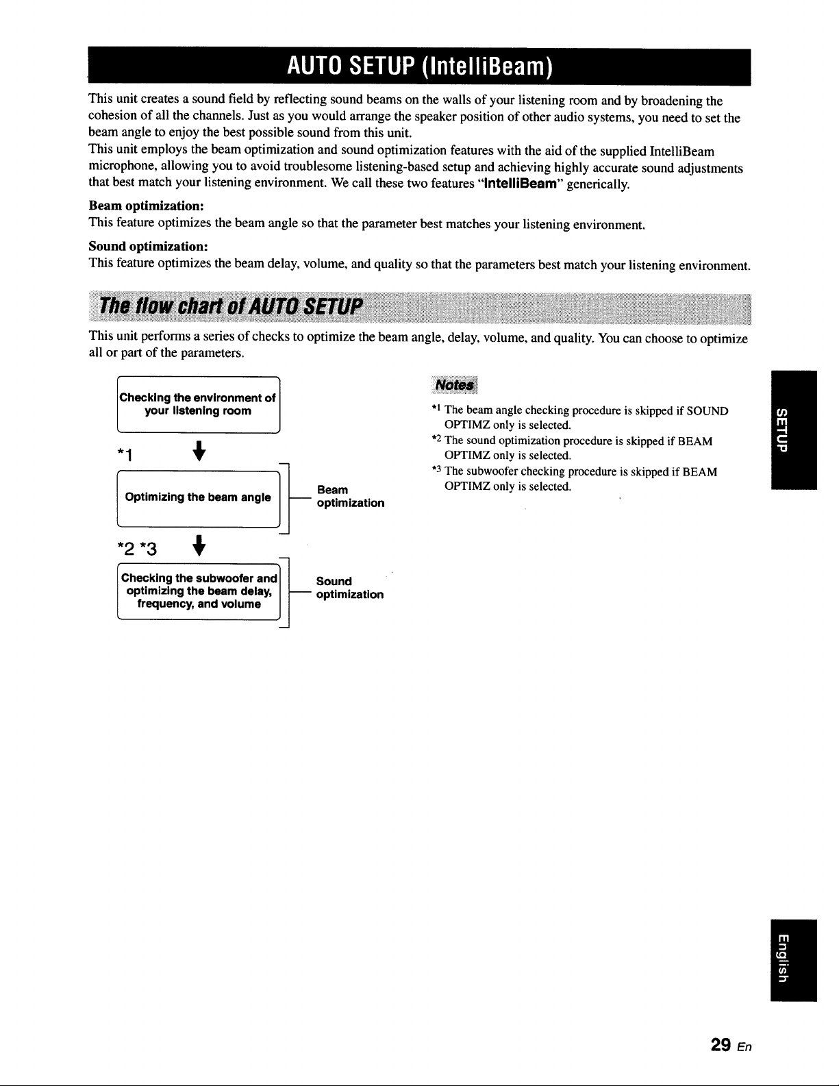
This unit performs a series of checks to optimize the beam angle, delay, volume, and quality. You can choose to optimize
all or part of the parameters.
Checking the environment of J
your listening room ]
-1 €
I Optimizing the beam angle ]J
*2 *3
"Checking the subwoofer and_-_
optimizing the beam delay, J J--
frequency, and volume Jj
Beam
optimization
Sound
optimization
*1 The beam angle checking procedure is skipped if SOUND
OPTIMZ only is selected.
*2 The sound optimization procedure is skipped if BEAM
OPTIMZ only is selected.
"3 The subwoofer checking procedure is skipped if BEAM
OPTIMZ only is selected.
29 En
W,_|lBgeJ_]_lgl]:,lll'flr_ll1:::w.lm_!
The supplied IntelliBeam microphone collects and analyzes the sound that this unit produces in your actual listening
environment. Follow the procedure below to connect the IntelliBeam microphone to this unit and make sure that the
IntelliBeam microphone is placed in a proper location and that there are no large obstacles between the IntelliBeam
microphone and the walls in your listening room.
• After you have completed the AUTO SETUP procedure, be sure to disconnect the IntelliBeam microphone.
• The IntelliBeam microphone is sensitive to heat.
- Keep it away from direct sunlight.
- Do not place it on top of this unit.
• Do not connect the IntelliBeam microphone to an extension cable as doing so may result in an inaccurate sound optimization.
• An error may occur during the AUTO SETUP procedure if the IntelliBeam microphone is not properly placed in your listening room.
To avoid the possibility of an error:
- Do not place the IntelliBeam microphone to the extreme right or left from the center of this unit.
- Do not place the IntelliBeam microphone within 1.8 m (6.0 ft) from the front of this unit.
- Do not place the IntelliBeam microphone more than 1 m (3.3 ft) upper or lower from the center height of this unit.
• Make sure that there are no obstacles between the lntelliBeam microphone and the walls in your listening room as these objects
obstruct the path of sound beams. However, any objects that are in contact with the walls will be regarded as a protruding part of the
walls.
• The best possible results are achieved if the IntelliBeam microphone is placed at the same height as your ears would be when you are
seated in your listening position. However, if this is not possible, you can manually fine-tune the sound beam angle and balance the
sound beam output levels using MANUAL SETUP (see page 74) once the AUTO SETUP procedure is completed.
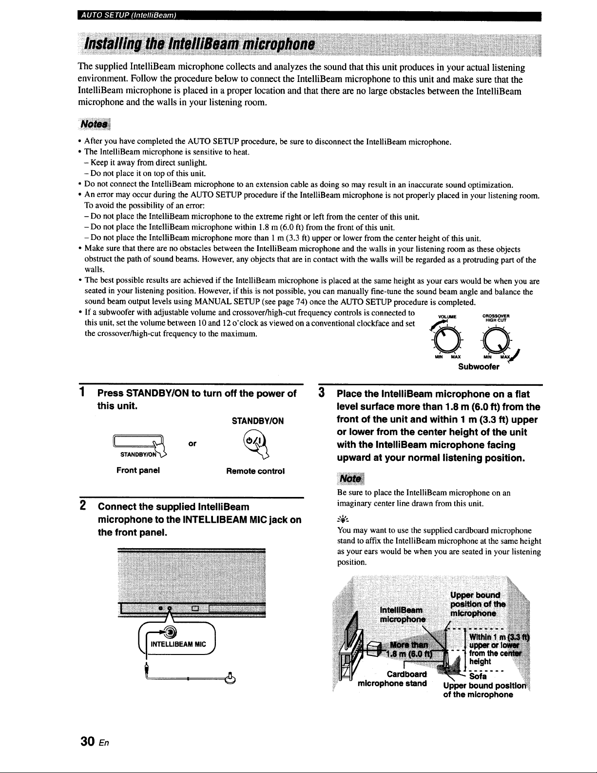
• If a subwoofer with adjustable volume and crossover/high-cut frequency controls is connected to
VOLUME CROSSOVER
this unit, set the volume between 10 and 12 o'clock as viewed on a conventional clockface and set ,_,_, H,_.e.ur
the crossover/high-cut frequency to the maximum.
Qj
MIN MAX M
Subwoofer
2
Press STANDBYION to turn off the power of
this unit.
STANDBYION
Front panel Remote control
Connect the supplied IntelliBeam
microphone to the INTELLIBEAM MIC jack on
the front panel.
3
Place the IntelliBeam microphone on a flat
level surface more than 1.8 m (6.0 ft) from the
front of the unit and within 1 m (3.3 ft) upper
or lower from the center height of the unit
with the IntelliBeam microphone facing
upward at your normal listening position,
Be sure to place the lntelliBeam microphone on an
imaginary center line drawn from this unit.
You may want to use the supplied cardboard microphone
stand to affix the IntelliBeam microphone at the same height
as your ears would be when you are seated in your listening
position.
Cardboard
microphone stand
from
Sofa ,,,_,_,_
Upper bound positio_ili
of the microphone
30 E,
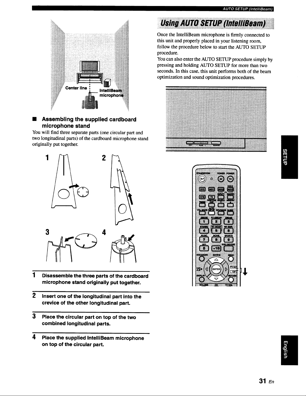
Center line i
.|llgeJk'}:lllJ:lilii_llll:x:_lli!
Once the IntelliBeam microphone is firmly connected to
this unit and properly placed in your listening room,
follow the procedure below to start the AUTO SETUP
procedure.
You can also enter the AUTO SETUP procedure simply by
pressing and holding AUTO SETUP for more than two
seconds. In this case, this unit performs both of the beam
optimization and sound optimization procedures.
• Assembling the supplied cardboard
microphone stand
You will find three separate parts (one circular part and
two longitudinal parts) of the cardboard microphone stand
originally put together.
1
2
1
2
3
4
3 4
Disassemble the three parts of the cardboard
microphone stand originally put together.
Insert one of the longitudinal part into the
crevice of the other longitudinal part.
Place the circular part on top of the two
combined longitudinal parts.
Place the supplied IntelliBeam microphone
on top of the circular part.
31 E,
W'.|lBg#J_"]_glP.ilITi_lll:l'._.lmJ!
• Make sure that your listening room is as quiet as possible while
this unit is performing the AUTO SETUP procedure.
• To achieve the best results possible, evacuate yourself from
your listening room until the AUTO SETUP procedure is
completed so that you may not obstruct the path of sound
beams.
• Be advised that it is normal for loud test tones to be output
during the AUTO SETUP procedure.
• The AUTO SETUP procedure may not be run successfully if
this unit is installed in one of the rooms described in "Before
installing this unit" on page 13. In such cases, run MANUAL
SETUP (see page 74) to manually adjust the corresponding
parameters.
• If an error occurs, an error buzzer is played, the AUTO SETUP
procedure stops, and an error message appears on the screen.
See "Error messages for AUTO SETUP" on page 35 for
appropriate remedies.
.%,..
• The AUTO SETUP procedure takes about three minutes
maximum. A chime is played when the AUTO SETUP
procedure is run successfully.
• If there are curtains in your listening room, we recommend
following the procedure below.
1. Open the curtains to improve sound reflection.
2. Run BEAM OPTIMZ only.
3. Close the curtains.
4. Run SOUND Ot_IMZ only.
• You can save the settings optimized by the AUTO SETUP
procedure (see page 36). A set of settings optimized according
to the specific conditions of your listening environment can be
recalled later depending on the varying conditions of your
listening environment (see page 37).
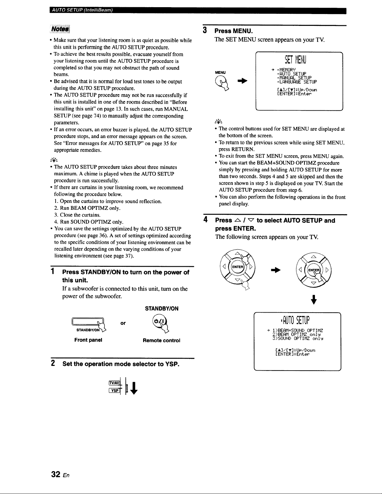
Press STANDBY/ON to turn on the power of
this unit.
If a subwoofer is connected to this unit, turn on the
power of the subwoofer.
Front panel
or
STANDBY/ON
Remote control
2 Set the operation mode selector to YSP.
3
4
Press MENU.
The SET MENU screen appears on your TV.
MENU
SETMENU
÷ .HEHORY
.RUT0 SETUP
• HRNURLSETUP
• LRNGUR6ESETUP
[a]/[v]:UP/[)own
[EHTER]:EnteP
• The control buttons used for SET MENU are displayed at
the bottom of the screen.
• To return to the previous screen while using SET MENU,
press RETURN.
• To exit from the SET MENU screen, press MENU again.
• You can start the BEAM+SOUND OPTIMZ procedure
simply by pressing and holding AUTO SETUP for more
than two seconds. Steps 4 and 5 are skipped and then the
screen shown in step 5 is displayed on your TV. Start the
AUTO SETUP procedure from step 6.
• You can also perform the following operations in the front
panel display.
Press/'- I _ to select AUTO SETUP and
press ENTER.
The following screenappearson your TV.
,.°.
€
I_ I
,AUTO:,ETUF
÷ i",BEI:IH+SOUND OPTIHZ
2,"BEAM OPTIHZ onl_
3)SOUHD OPTIMZ only
[A]/[_] :UP/Do_Jn
[ENTER] :Enter
32 En
, lll g#____ _ lll ".il lil r_il ll-_ :_.:.m l
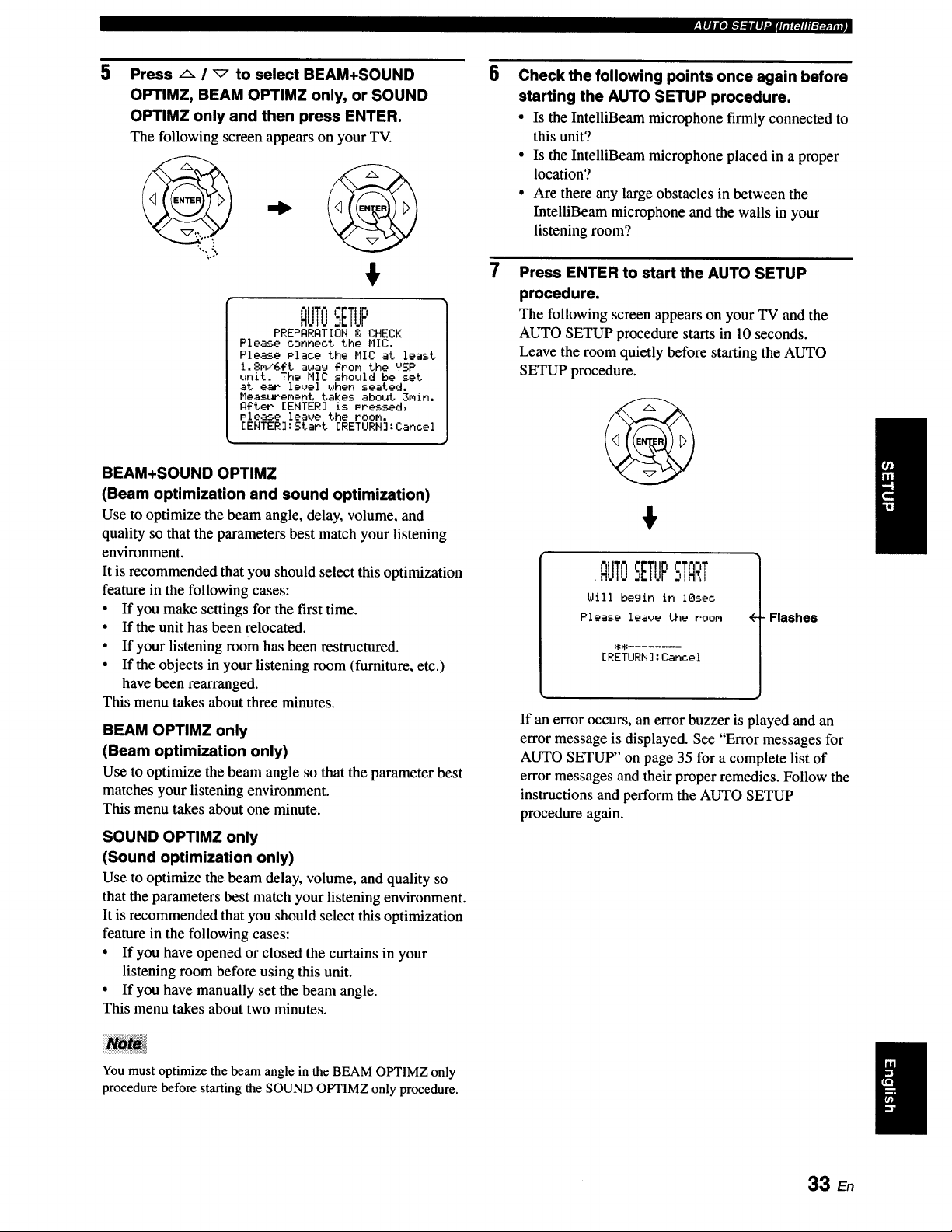
5
Press a / _ to select BEAM+SOUND
OPTIMZ, BEAM OPTIMZ only, or SOUND
OPTIMZ only and then press ENTER.
The following screen appears on your TV.
"-1°).
$
QUTOSETUP
PREPQRQTION & CHECK
Please connect the HIC,
Please Place the MIC at least
1.8m/GFt a_a_ ?tom the YSP
unit. The MIC should be set
at ear level _Jhen seated.
Measurement takes about 3min.
Qgter [ENTER] is Pressed,
Please leave the room.
[ENTER]:Start ERETURN]:Cancel
BEAM+SOUND OPTIMZ
(Beam optimization and sound optimization)
Use to optimize the beam angle, delay, volume, and
quality so that the parameters best match your listening
environment.
It is recommended that you should select this optimization
feature in the following cases:
• If you make settings for the first time.
• If the unit has been relocated.
• If your listening room has been restructured.
• If the objects in your listening room (furniture, etc.)
have been rearranged.
This menu takes about three minutes.
BEAM OPTIMZ only
(Beam optimization only)
Use to optimize the beam angle so that the parameter best
matches your listening environment.
This menu takes about one minute.
SOUND OPTIMZ only
(Sound optimization only)
Use to optimize the beam delay, volume, and quality so
that the parameters best match your listening environment.
It is recommended that you should select this optimization
feature in the following cases:
• If you have opened or closed the curtains in your
listening room before using this unit.
• If you have manually set the beam angle.
This menu takes about two minutes.
6
Check the following points once again before
starting the AUTO SETUP procedure.
• Is the IntelliBeam microphone firmly connected to
this unit?
• Is the IntelliBeam microphone placed in a proper
location?
• Are there any large obstacles in between the
IntelliBeam microphone and the walls in your
listening room?
Press ENTER to start the AUTO SETUP
procedure.
The following screenappearson your TV andthe
AUTO SETUP procedure starts in 10 seconds.
Leave the room quietly before starting the AUTO
SETUP procedure.
$
.QIJTOSETUP
Will begin in iOsec
Please leave the room
[RETURN]:Cancel
-Flashes
If an error occurs, an error buzzer is played and an
error message is displayed. See "Error messages for
AUTO SETUP" on page 35 for a complete list of
error messages and their proper remedies. Follow the
instructions and perform the AUTO SETUP
procedure again.
You must optimize the beam angle in the BEAM OPTIMZ only
procedure before starling the SOUND OPTIMZ only procedure.
I
33 En
W_,111J[o]_.'l :l l |l "Jl rfl _J l tl gr:_. ; . ]
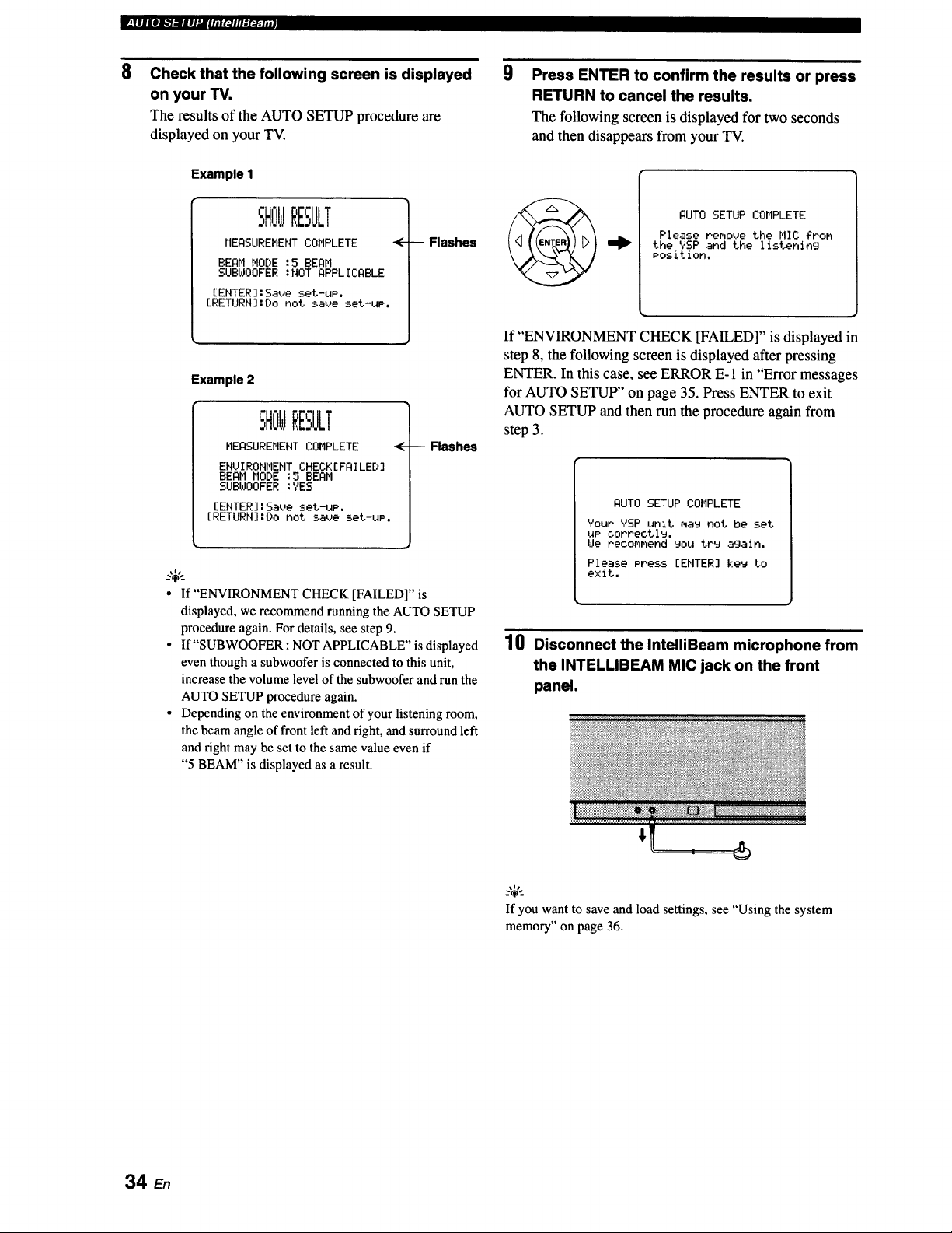
8
Check that the following screen is displayed
on your TV.
The results of the AUTO SETUP procedure are
displayed on your TV.
Example I
SHOWRESULT
MEASUREMENT COMPLETE <
BEAM MODE :5 BEAM
SUBWOOFER :NOT APPLICABLE
[ENTER]:Saue set-uP.
[RETURN]:Do not save set-uP.
--Flashes
Example 2
SHOWRESULT
MEASUREMENT COMPLETE
ENUIRONMEHT CHECK[FAILED]
BEAM MODE :5 BEAM
SUBWOOFER :YES
[ENTER]:Saue set-uP,
[RETURH]:Do not save set-uP.
-- Flashes
• If"ENVIRONMENT CHECK [FAILED]" is
displayed, we recommend running the AUTO SETUP
procedureagain. For details, see step 9.
• If"SUBWOOFER : NOTAPPLICABLE"isdisplayed
eventhough a subwooferis connected to this unit,
increase the volumelevelof the subwooferandrun the
AUTOSETUP procedure again.
• Depending on theenvironmentof your listening room,
the beam angle of front left andright, and surroundleft
and right may be set to the same valueeven if
"5 BEAM" is displayed as a result.
9
Press ENTER to confirm the results or press
RETURN to cancel the results.
The following screen is displayed for two seconds
and then disappears from your TV.
AUTO SETUP COMPLETE
Please remove the MIC ?non
the VSP and the listening
Position.
If "ENVIRONMENT CHECK [FAILED]" is displayed in
step 8, the following screen is displayed after pressing
ENTER. In this case, see ERROR E- 1 in "Error messages
for AUTO SETUP" on page 35. Press ENTER to exit
AUTO SETUP and then run the procedure again from
step 3.
AUTO SETUP COMPLETE
Your YSP unit r_aw not be set
LIP correctl_.
We recoMnend you tr_ again.
Please Press [ENTER] key to
exit.
10
Disconnect the IntelliBeam microphone from
the INTELLIBEAM MIC jack on the front
panel,
_-'_,..
If you want to save and load settings, see "Using the system
memory" on page 36.
34
..tEjgeJ_]qlgJJ'.Jrtl_l_llTa:=i,;l,!
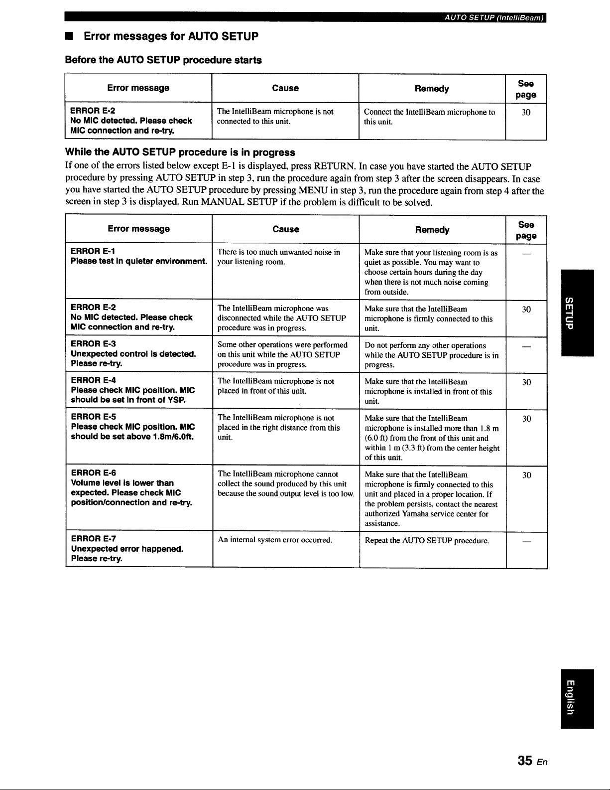
• Error messages for AUTO SETUP
Before the AUTO SETUP procedure starts
See
Error message Cause Remedy
page
ERROR E-2 The IntelliBeam microphone is not Connect the lntelliBeam microphone to 30
No MIC detected. Please check connected to this unit. this unit.
MIC connection and re-try.
While the AUTO SETUP procedure is in progress
If one of the errors listed below except E-1 is displayed, press RETURN. In case you have started the AUTO SETUP
procedure by pressing AUTO SETUP in step 3, run the procedure again from step 3 after the screen disappears. In case
you have started the AUTO SETUP procedure by pressing MENU in step 3, run the procedure again from step 4 after the
screen in step 3 is displayed. Run MANUAL SETUP if the problem is difficult to be solved.
Error message
ERROR E-1
Please test In quieter envlronment.
ERROR E-2
NO MIC detected. Please check
MIC connection and re-try.
ERROR E-3
Unexpected control is detected.
Please re-try.
ERROR E-4
Please check MIC posltlon. MIC
should be set in front of YSR
ERROR E-5
Please check MIC position. MIC
should be set above 1.8m/6.0ft.
ERROR E-6
Volume level is lower than
expected. Please check MIC
position/connection and re-try.
ERROR E-7
Unexpected error happened.
Please re-try.
Cause
There is too much unwanted noise in
your listening room.
The IntelliBeam microphone was
disconnected while the AUTO SETUP
procedure was in progress.
Some other operations were performed
on this unit while the AUTO SETUP
procedure was in progress.
The lntelliBeam microphone is not
placed in front of this unit.
The IntelliBeam microphone is not
placed in the fight distance from this
unit.
The IntelliBeam microphone cannot
collect the sound produced by this unit
because the sound output level is too low.
An internal system error occurred.
See
Remedy
page
Make sure that your listening room is as
quiet as possible. You may want to
choose certain hours during the day
when there is not much noise coming
from outside.
Make sure that the IntelliBeam
microphone is firmly connected to this
unit.
30
Do not perform any other operations
while the AUTO SETUP procedure is in
progress.
Make sure that the lntelliBeam 30
microphone is installed in front of this
unit.
Make sure that the IntelliBeam
microphone is installed more than 1.8 m
(6.0 ft) from the front of this unit and
within 1 m (3.3 ft) from the center height
of this unit.
Make sure that the lntelliBeam
microphone is firmly connected to this
unit and placed in a proper location. If
the problem persists, contact the nearest
authorized Yamaha service center tbr
assistance.
Repeat the AUTO SETUP procedure.
30
30
35 En
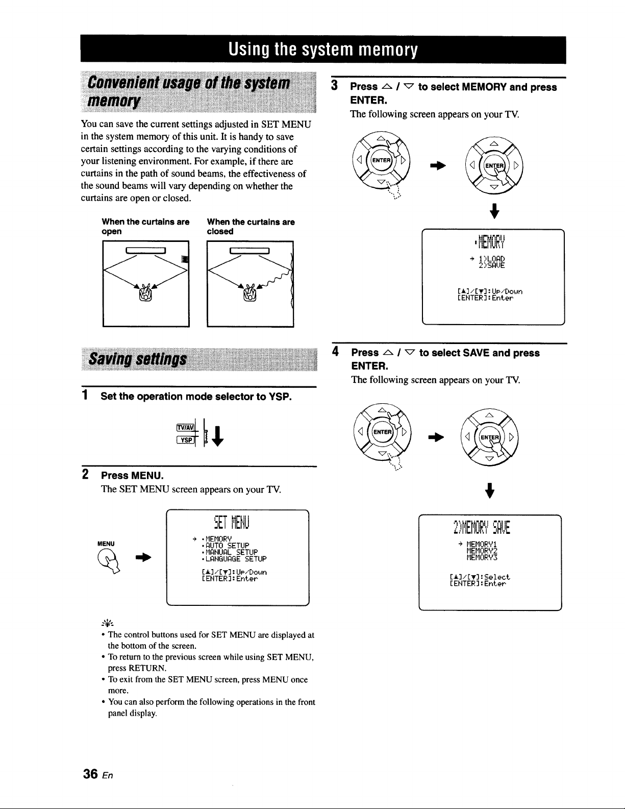
You can save the current settings adjusted in SET MENU
in the system memory of this unit. It is handy to save
certain settings according to the varying conditions of
your listening environment. For example, if there are
curtains in the path of sound beams, the effectiveness of
the sound beams will vary depending on whether the
curtains are open or closed.
When the curtains are When the curtains are
open closed
! I
%>
3
Press/'- I _ to select MEMORY and press
ENTER.
The following screen appearson your TV.
#
,MEMORY
÷ 1:,LORD
2)SAUE
[_]/[It] : UP/Do,in
[ENTER] : Enter
1
Set the operation mode selector to YSP.
Press MENU.
The SET MENU screen appears on your TV.
MENU
I
SETMEHJ
+ .MEMORY
.flUTO SETUP
.HgNURL SETUP
• LANGUAGE SETUP
[_] ,,[_r]: UP/Dol,m
[EHTER] : Enter
4
Press/x i _ to select SAVE and press
ENTER.
The following screen appearson your TV.
4,
2)HEI'IOR',/SFIVE
+ MEHORY1
MEHORY2
MEMORY3
[_]/[_]:Select
[EHTER]:Enter
• The control buttons used for SET MENU are displayed at
the bottom of the screen.
• To return to the previousscreen while using SET MENU,
press RETURN.
• To exit from the SET MENU screen,press MENUonce
more.
• Youcan also performthe followingoperations in thefront
paneldisplay.
36 en
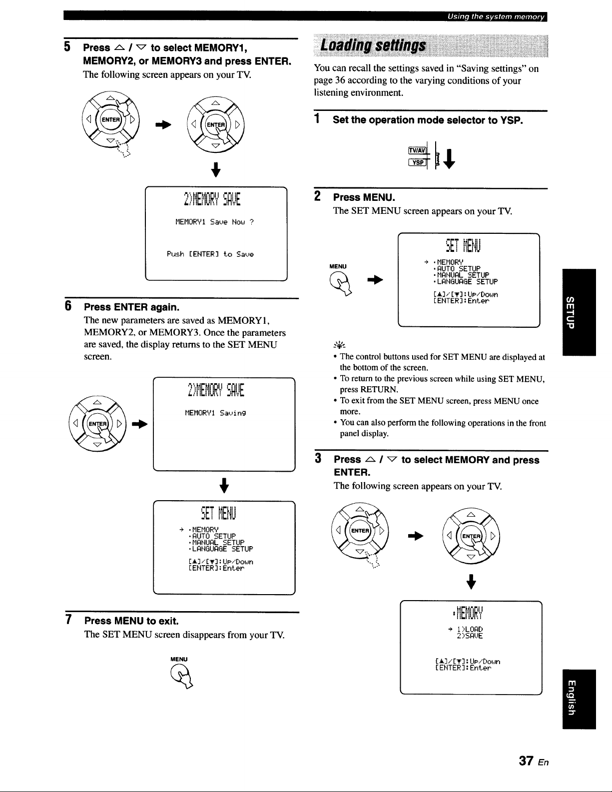
m4,._l|i_,IImt_.l,l_",lg_m_ii,lt_#mlelA
5
B
Press A / _ to select MEMORY1,
MEMORY2, or MEMORY3 and press ENTER.
The following screen appears on your TV.
2)HB'IORYSAUE
MEMORY1 Save Flow ?
Push [ENTER] to Save
Press ENTER again.
The new parameters are saved as MEMORY 1,
MEMORY2, or MEMORY3. Once the parameters
are saved, the display returns to the SET MENU
screen.
7
2)HEHORYSAUE
MEMORYI Saving
÷ .MEMORY
•AUTO SETUP
•MANUAL SETUP
•LANGUAGE SETUP
[_]/[_]:IJp/Down
[EHTER]:EnteP
Press MENU to exit.
The SET MENU screen disappears from your TV.
MENU
You can recall the settings saved in "Saving settings" on
page 36 according to the varying conditions of your
listening environment.
1 Set the operation mode selector to YSP.
2 Press MENU.
The SET MENU screen appears on your TV.
MENU
SETMENU
÷ .MEMORY
•AUTO SETUP
•MANUAL SETUP
•LANGUAGE SETUP
[a],'E_]:UP/Down
[ENTER]:EnteP
3
• The control buttons used for SET MENU are displayed at
the bottom of the screen•
• To return to the previous screen while using SET MENU,
press RETURN.
• To exit from the SET MENU screen, press MENU once
more.
• You can also perform the following operations in the front
panel display•
Press A i _ to select MEMORY and press
ENTER.
The following screen appears on your TV.
,..,
$
mIII.II.I',,I
+ I)LOAD
2)SAUE
[a],"[_F]:UP/DobJn
[ENTER ]:Enter
I
37 En
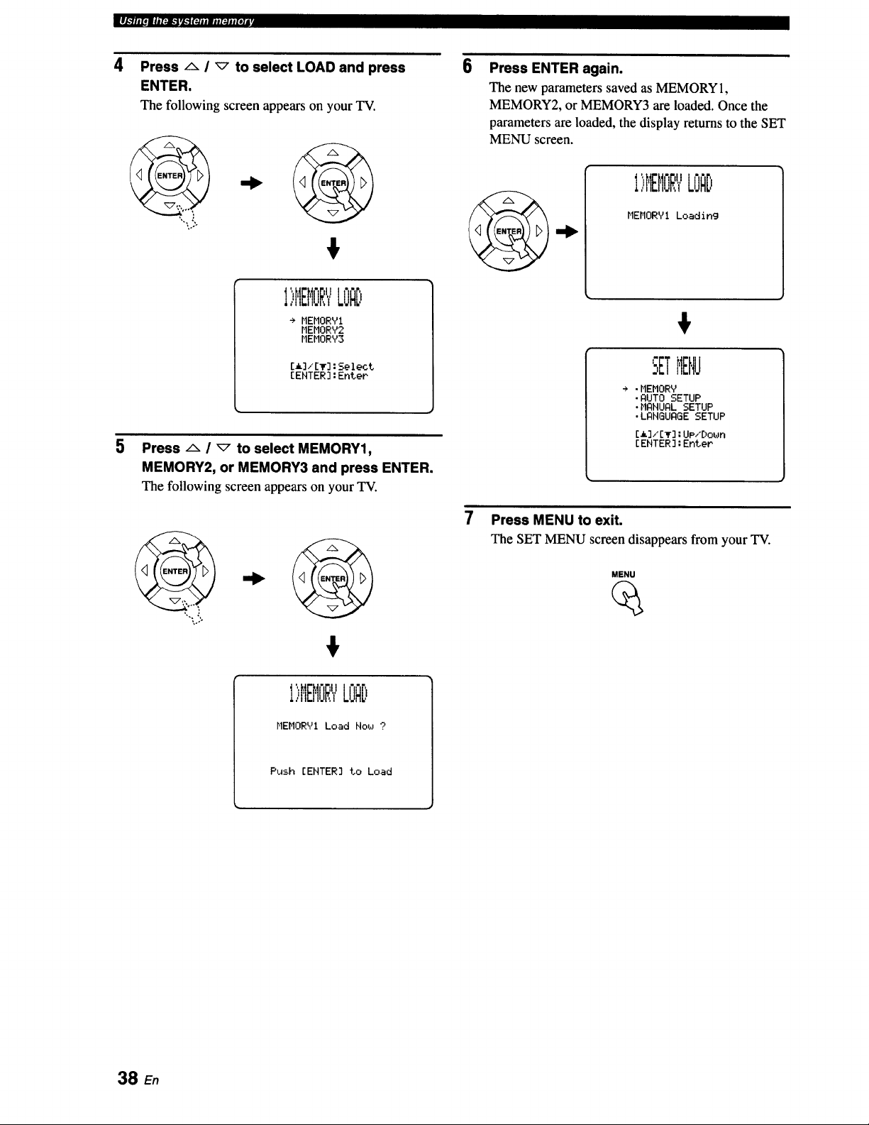
IJl_llitOmll[_l_ir_lf_jjmjjI_jjf_la
4
5
Press/x / _ to select LOAD and press
ENTER.
The following screen appears on your TV.
6
,o°-
€
I',:,HEI'IORYLOAD
÷ MEHORYI
r,IEMORY2
MEMORY3
[_]/[T]:Select
[ENTER]:Enter
Press A / _ to select MEMORY1,
MEMORY2, or MEMORY3 and press ENTER.
The following screen appears on your TV.
Press ENTER again.
The new parameters saved as MEMORY 1,
MEMORY2, or MEMORY3 are loaded. Once the
parameters are loaded, the display returns to the SET
MENU screen.
_l I "dl
I,,MEMuR_,LOAD
MEMORY! Loading
€
".ETMENU
÷ .MEMORY
•AUTO SETUP
.MANUAL SETUP
.LANGUAGE SETUP
[a]/[T]:UP/[)own
[ENTER]:EnteP
•,..:
7
Press MENU to exit.
The SET MENU screen disappears from your TV.
MENU
€
1)MEMORYLOAD
MEHORYI Load Now ?
Push [EHTER] to Load
38 En
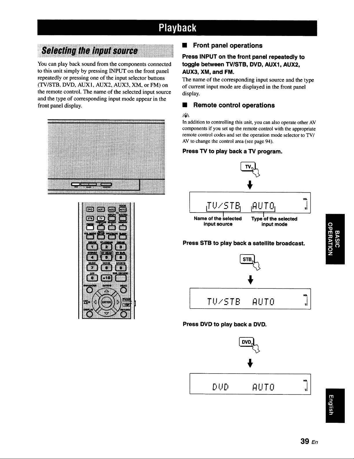
You can play back sound from the components connected
to this unit simply by pressing INPUT on the front panel
repeatedly or pressing one of the input selector buttons
(TV/STB, DVD, AUXI, AUX2, AUX3, XM, or FM) on
the remote control. The name of the selected input source
and the type of corresponding input mode appear in the
front panel display.
• Front panel operations
Press INPUT on the front panel repeatedly to
toggle between TV/STB, DVD, AUX1, AUX2,
AUX3, XM, and FM.
The name of the corresponding input source and the type
of current input mode are displayed in the front panel
display.
• Remote control operations
:,_,.
In addition to controlling this unit, you can also operate other AV
components if you set up the remotecontrol with the appropriate
remote control codes and set the operation mode selector to TV/
AVto change thecontrol area (see page 94).
Press TV to play back a TV program.
iTt.J....'_-:TBI
/
Name of the _elected
input source
ifl !.!T 0I
Type Iof the selected
input mode
VOL
i
:i
Press STB to play back a satellite broadcast.
Tt,_....5TB _UTO ,_
Press DVD to play back a DVD.
I
E:,tJ_., _!i_iTO
39 E,
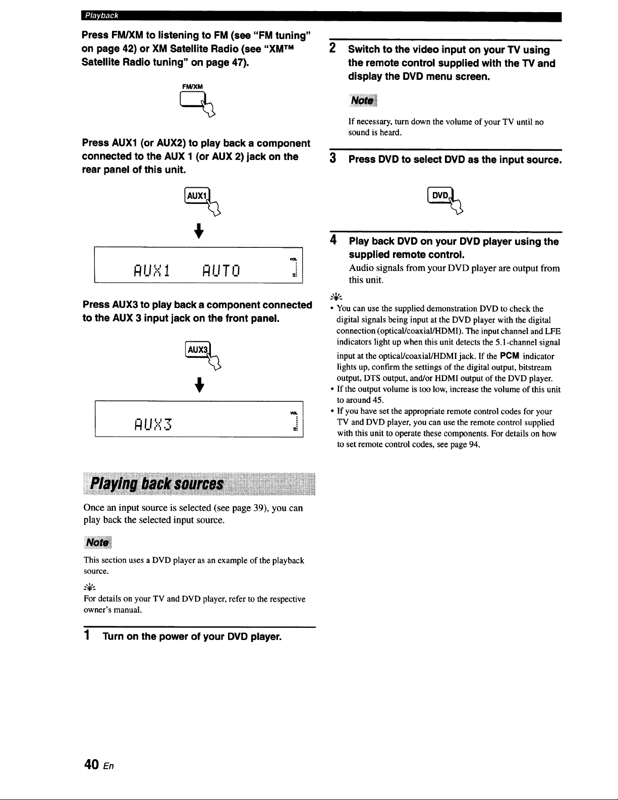
lum,/_i
Press FM/XM to listening to FM (see "FM tuning"
on page 42) or XM Satellite Radio (see "XM TM
Satellite Radio tuning" on page 47).
FM/XM
Switch to the video input on your TV using
the remote control supplied with the TV and
display the DVD menu screen.
Press AUX1 (or AUX2) to play back a component
connected to the AUX 1 (or AUX 2) jack on the
rear panel of this unit.
LI I U T0 :i
Press AUX3 to play back a component connected
to the AUX 3 input jack on the front panel.
€
Once an input source is selected (see page 39), you can
play back the selected input source.
If necessary, turn down the volume of your TV until no
sound is heard.
3 Press DVD to select DVD as the input source.
4
_.,;,._
Play back DVD on your DVD player using the
supplied remote control.
Audio signals from your DVD player are output from
this unit.
• You can use the supplied demonstration DVD to check the
digital signals being input at the DVD player with the digital
connection (optical/coaxial/HDMI). The input channel and LFE
indicators light up when this unit detects the 5.1-channel signal
input at the optical/coaxial/HDMl jack. If the PCM indicator
lights up, confirm the settings of the digital output, bitstream
output, DTS output, and/or HDMI output of the DVD player.
• If the output volume is too low, increase the volume of this unit
to around 45.
• If you have set the appropriate remote control codes for your
TV and DVD player, you can use the remote control supplied
with this unit to operate these components. For details on how
to set remote control codes, see page 94.
This section uses a DVD player as an example of the playback
SOUrCe.
For details on your TV and DVD player, refer to the respective
owner's manual.
1 Turn on the power of your DVD player.
40 En
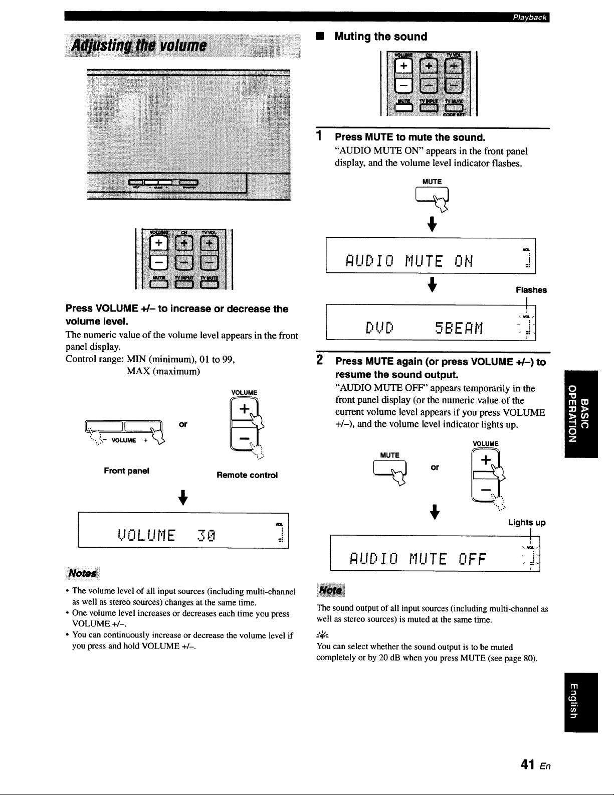
• Muting the sound
Press VOLUME +/- to increase or decrease the
volume level.
The numenc value of the volume level appears in the front
panel display.
Control range: MIN (minimum), 01 to 99,
MAX (maximum)
Front panel
or
VOLUME
"'L?o
Remote control
UOLUt'IE 3_ ::
• The volume level of all input sources (including multi-channel
as well as stereo sources) changes at the same time.
• One volume level increases or decreases each time you press
VOLUME +/-.
• You can continuously increase or decrease the volume level if
you press and hold VOLUME +/-.
Press MUTE to mute the sound.
"AUDIO MUTE ON" appears in the front panel
display, and the volume level indicator flashes.
MUTE
-I
I-'IUDI0 r,IUTE ON ,i
Flashes
2 Press MUTE again (or press VOLUME +1-) to
resume the sound output.
"AUDIO MUTE OFF" appears temporarily in the
front panel display (or the numeric value of the
current volume level appears if you press VOLUME
+/-), and the volume level indicator lights up.
MUTE
or
VOLUME
_UDIO r'IUTEOFF
Lights up
The sound output of all input sources (includingmulti-channel as
well as stereo sources) is muted at the same time.
Youcan select whether the sound output is to be muted
completely or by 20 dB when you press MUTE (see page 80).
41 En
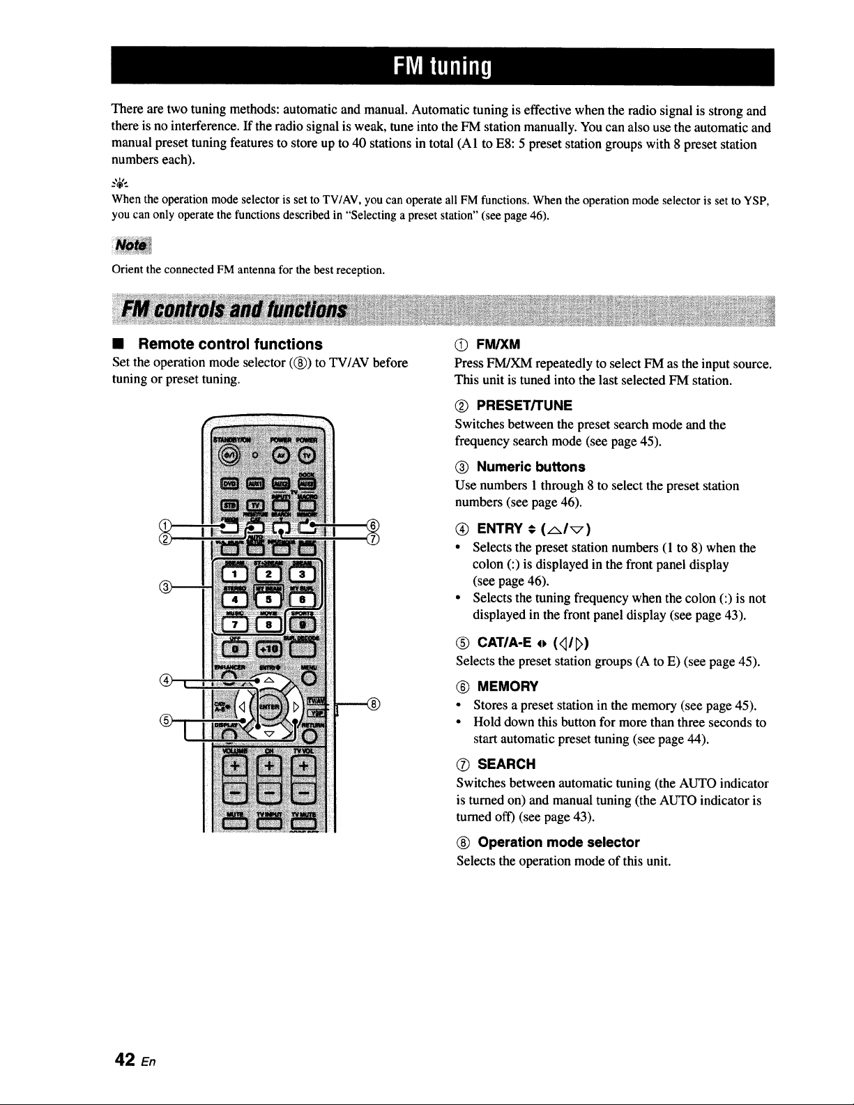
There are two tuning methods: automatic and manual. Automatic tuning is effective when the radio signal is strong and
there is no interference. If the radio signal is weak, tune into the FM station manually. You can also use the automatic and
manual preset tuning features to store up to 40 stations in total (AI to E8:5 preset station groups with 8 preset station
numbers each).
When the operationmode selectoris set to TV/AV,you can operate all FMfunctions. When the operation modeselector is set to YSP,
you can only operate the functions describedin "Selecting a preset station" (see page 46).
Orient the connected FM antenna for the best reception.
• Remote control functions
Set the operation mode selector ((_)) to TV/AV before
tuning or preset tuning.
O FM/XM
Press FM/XM repeatedly to select FM as the input source.
This unit is tuned into the last selected FM station.
(_) PRESET/TUNE
Switches between the preset search mode and the
frequency search mode (see page 45).
Numeric buttons
Use numbers 1 through 8 to select the preset station
numbers (see page 46).
ENTRY € (AI_)
• Selects the preset station numbers (1 to 8) when the
colon (:) is displayed in the front panel display
(see page 46).
• Selects the tuning frequency when the colon (:) is not
displayed in the front panel display (see page 43).
0 CATIA-E o (<_/_)
Selects the preset station groups (A to E) (see page 45).
® MEMORY
• Stores a preset station in the memory (see page 45).
• Hold down this button for more than three seconds to
start automatic preset tuning (see page 44).
O SEARCH
Switches between automatic tuning (the AUTO indicator
is turned on) and manual tuning (the AUTO indicator is
turned off) (see page 43).
(_) Operation mode selector
Selectsthe operation mode of this unit.
42 En
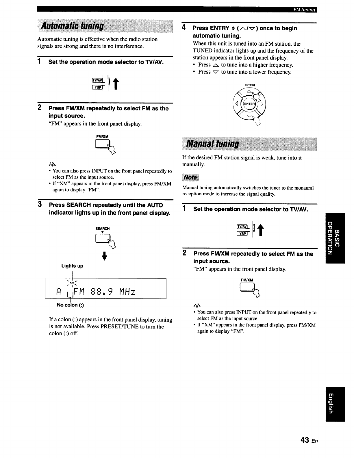
Automatic tuning is effective when the radio station
,1|ri|fqllllll ,,
signals are strong and there is no interference.
1 Set the operation mode selector to TV/AV.
3
Press FM/XM repeatedly to select FM as the
input source.
"FM" appears in the front panel display.
FM/XM
• You can also press INPUT on the front panel repeatedly to
select FM as the input source.
• If "XM" appears in the front panel display, press FM/XM
again to display "FM".
Press SEARCH repeatedly until the AUTO
indicator lights up in the front panel display.
Lights up
I
R LTjF'r'I
NO colon (:)
SEARCH
m-alz'l
,_-,.9 HHz
If a colon (:) appears in the front panel display, tuning
is not available. Press PRESET/TUNE to turn the
colon (:) off.
4
Press ENTRY # (AI_) once to begin
automatic tuning.
When this unit is tuned into an FM station, the
TUNED indicator lights up and the frequency of the
station appears in the front panel display.
• Press/x to tune into a higher frequency.
• Press _ to tune into a lower frequency.
ENTRYO
If the desired FM station signal is weak, tune into it
manually.
Manual tuning automatically switches the tuner to the monaural
reception mode to increase the signal quality.
1 Set the operation mode selector to TVIAV.
2
Press FM/XM repeatedly to select FM as the
input source.
"FM" appears in the front panel display.
FM/XM
--'4'--
• You can also press INPUT on the front panel repeatedly to
select FM as the input source.
• If "XM" appears in the front panel display,press FM/XM
again to display "FM".
43 E.
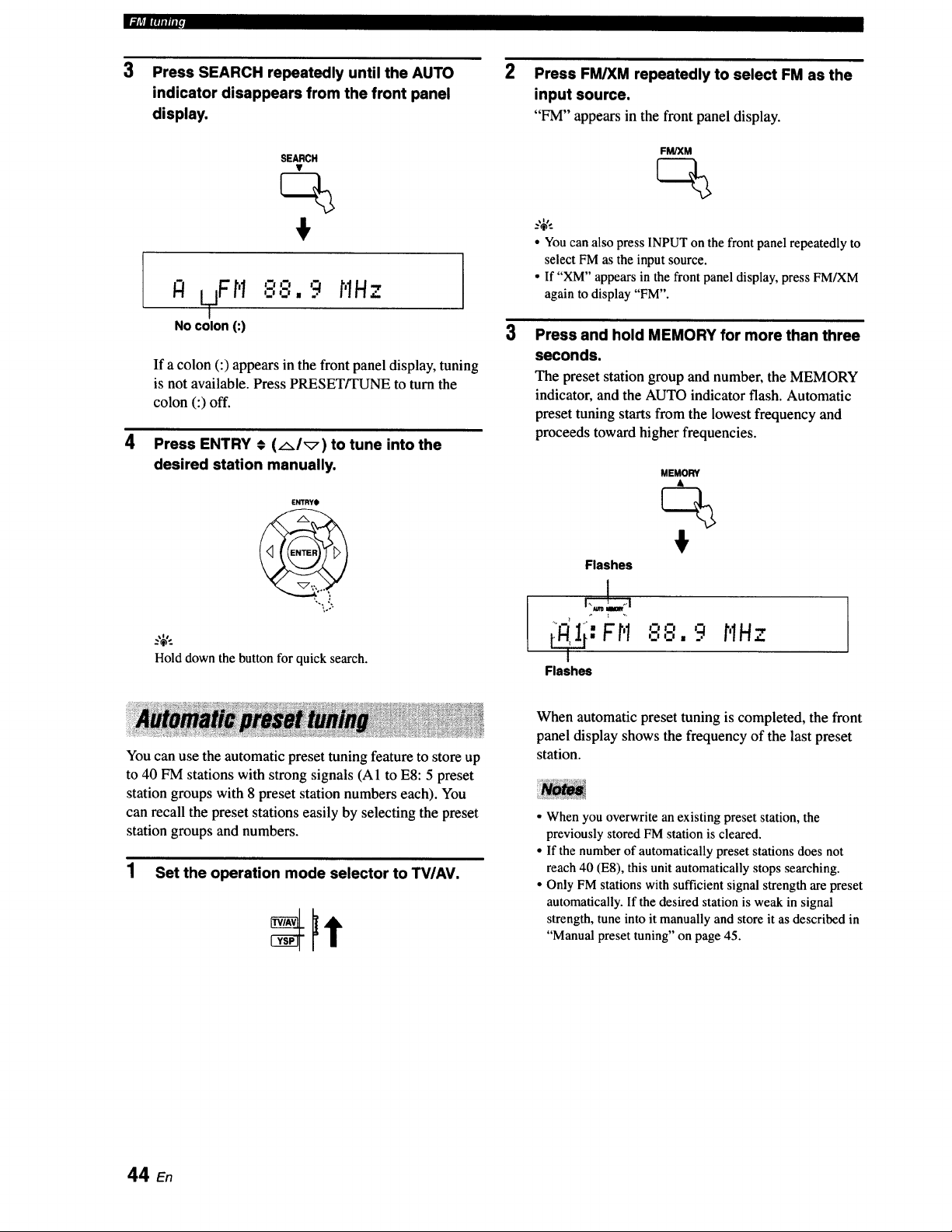
_]J_|lllllllll
3
4
Press SEARCH repeatedly until the AUTO
indicator disappears from the front panel
display.
2
Press FM/XM repeatedly to select FM as the
input source.
"FM" appears in the front panel display.
SEARCH
jFH o,-,
IZt LT ,.,o, 9 HH.7.
NO colon (:)
i
If a colon (:) appears in the front panel display, tuning
is not available. Press PRESET/TUNE to turn the
colon (:) off.
3
FM/XM
_.,$,,_
• Youcan also press INPUT onthe front panel repeatedly to
select FM as the input source.
• If "XM" appears in the front panel display,press FM/XM
again to display"FM".
Press ENTRY € (AI_) to tune into the
desired station manually. MEMORY
ENTRY_)
Flashes
Press and hold MEMORY for more than three
seconds.
The preset station group and number, the MEMORY
indicator, and the AUTO indicator flash. Automatic
preset tuning starts from the lowest frequency and
proceeds toward higher frequencies.
..,.. Fr,1 ,'.-','8,9
Hold downthe button for quick search.
Flashes
HHz ]
You can use the automatic preset tuning feature to store up
to 40 FM stations with strong signals (A1 to E8:5 preset
station groups with 8 preset station numbers each). You
can recall the preset stations easily by selecting the preset
station groups and numbers.
1 Set the operation mode selector to TV/AV.
When automatic preset tuning is completed, the front
panel display shows the frequency of the last preset
station.
• When you overwrite an existing preset station, the
previously stored FM station is cleared.
• If the number of automatically preset stations does not
reach 40 (E8), this unit automatically stops searching.
• Only FM stations with sufficient signal strength are preset
automatically. If the desired station is weak in signal
strength, tune into it manually and store it as described in
"Manual preset tuning" on page 45.
44 En
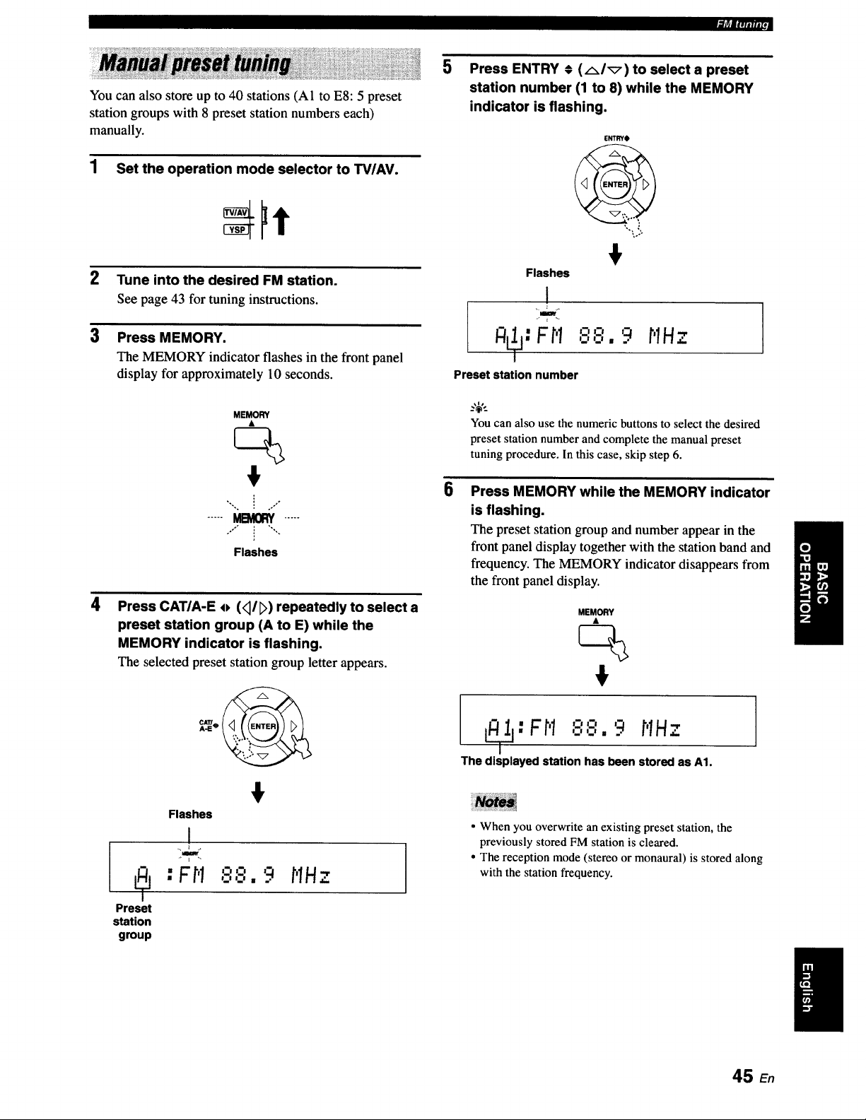
|l_llqlllllJ
You can also store up to 40 stations (A1 to E8:5 preset
station groups with 8 preset station numbers each)
manually.
1 Set the operation mode selector to TV/AV.
2
3
Tune into the desired FM station.
See page 43 for tuning instructions.
Press MEMORY.
The MEMORY indicator flashes in the front panel
display for approximately 10 seconds.
MEMORY
ck
",. i
,. .7 °
,,°" i "",,
I
Flashes
4
Press CAT/A-E o (_]/D) repeatedly to select a
preset station group (A to E) while the
MEMORY indicator is flashing.
The selected preset station group letter appears.
Flashes
I
mlw
: Fi"I '-"'-" "_ MHz
IIl ImI I
Preset
station
group
5
Press ENTRY € (AI_) to select a preset
station number (1 to 8) while the MEMORY
indicator is flashing.
ENTRYO
Flashes
1
I
iimy
_: FM
oo g MHz
_.J _.J I .
Preset station number
You can also use the numeric buttons to select the desired
preset station number and complete the manual preset
tuning procedure. In this case, skip step 6.
6
Press MEMORY while the MEMORY indicator
is flashing.
The preset station group and number appear in the
front panel display together with the station band and
frequency. The MEMORY indicator disappears from
the front panel display.
MEMORY
L_T_:Ft'I88, 9 MHz
The displayed station has been stored as A1.
• When you overwrite an existing preset station, the
previously stored FM station is cleared.
• The reception mode (stereo or monaural) is stored along
with the station frequency.
I
45 E.
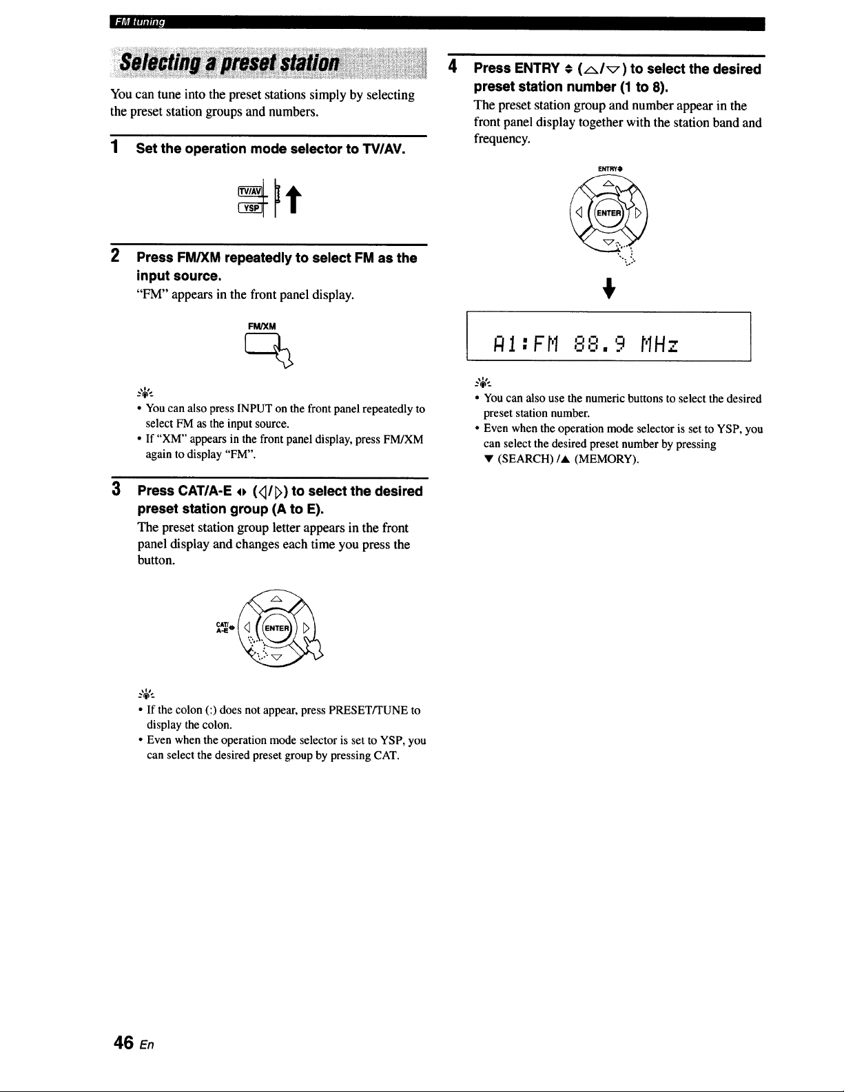
|.,_|_|lllilliZd
You can tune into the preset stations simply by selecting
the preset station groups and numbers.
1 Set the operation mode selector to TV/AV.
3
Press FM/XM repeatedly to select FM as the
input source.
"FM" appears in the front panel display.
FM/XM
• Youcan also press INPUTon the front panelrepeatedly to
select FM as the input source.
• If "XM" appears in the front panel display,press FM/XM
again to display "FM".
Press CATIA-E o (<I/E>)to select the desired
preset station group (A to E).
The preset station group letter appears in the front
panel display and changes each time you press the
button.
• If the colon (:) does not appear, press PRESET/TUNE to
display the colon.
• Even when the operation mode selector is set to YSP, you
can select the desired preset group by pressing CAT.
4
Press ENTRY # (AI_) to select the desired
preset station number (1 to 8).
The preset station group and number appear in the
front panel display together with the station band and
frequency.
ENTRYO
?,o.
:o.-
fftl " F r'I '="=' r'lH
t.m _w m . ..r
• Youcan also use the numeric buttons to select the desired
preset stationnumber.
• Even whenthe operation mode selector is setto YSP, you
can select the desiredpreset number by pressing
v (SEARCH)/A (MEMORY).
46 E.
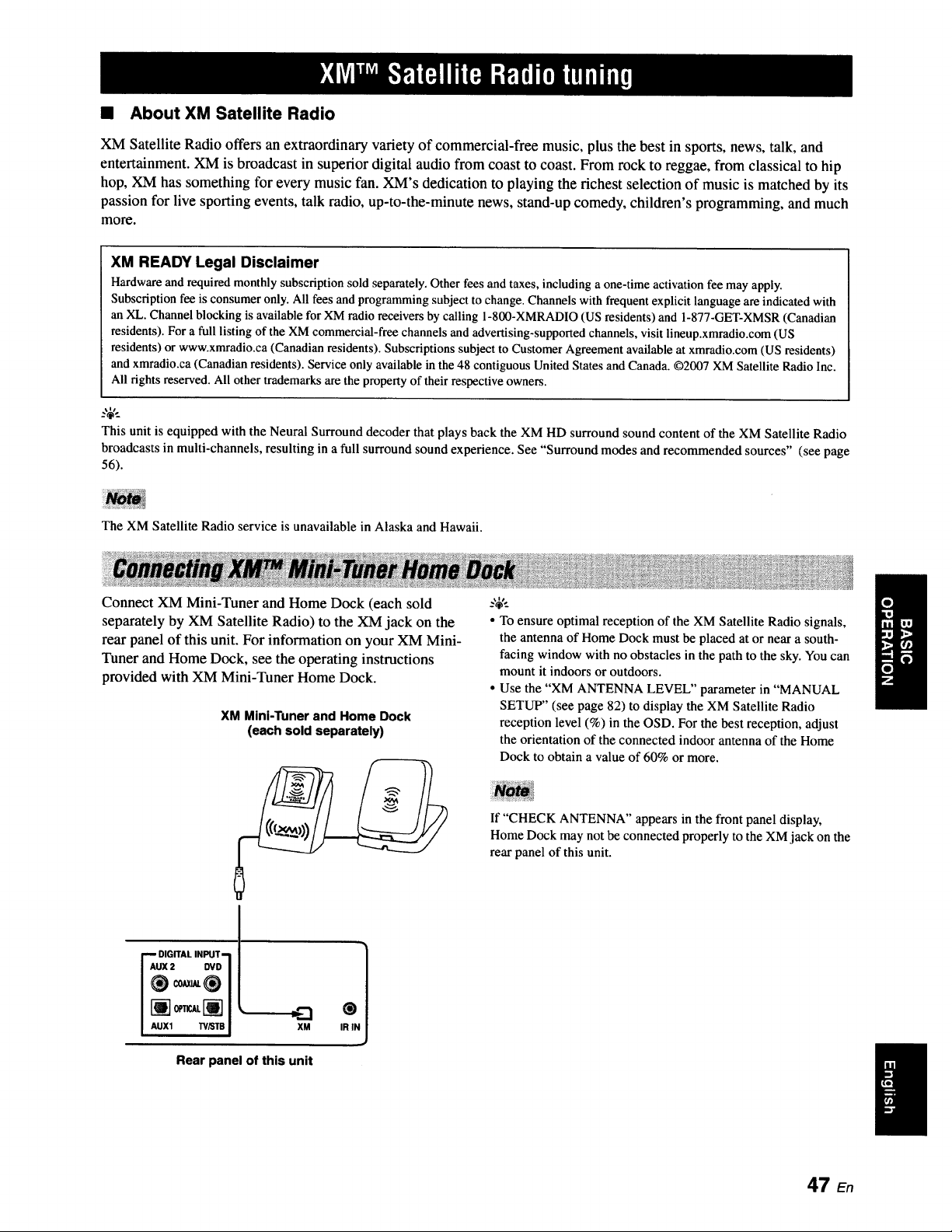
• About XM Satellite Radio
XM Satellite Radio offers an extraordinary variety of commercial-free music, plus the best in sports, news, talk, and
entelxainment. XM is broadcast in superior digital audio from coast to coast. From rock to reggae, from classical to hip
hop, XM has something for every music fan. XM's dedication to playing the richest selection of music is matched by its
passion for live sporting events, talk radio, up-to-the-minute news, stand-up comedy, children's programming, and much
more.
XM READY Legal Disclaimer
Hardware and required monthly subscription sold separately. Other fees and taxes, including a one-time activation fee may apply.
Subscription fee is consumer only. All fees and programming subject to change. Channels with frequent explicit language are indicated with
an XL. Channel blocking is available for XM radio receivers by calling 1-800-XMRADIO (US residents) and 1-877-GET-XMSR (Canadian
residents). For a full listing of the XM commercial-free channels and advertising-supported channels, visit lineup.xmradio.com (US
residents) or www.xmradio.ca (Canadian residents). Subscriptions subject to Customer Agreement available at xmradio.com (US residents)
and xmradio.ca (Canadian residents). Service only available in the 48 contiguous United States and Canada. 02007 XM Satellite Radio Inc.
All rights reserved. All othertrademarksare the propertyof their respective owners.
This unit is equipped with the Neural Surround decoder that plays back the XM HD surround sound content of the XM Satellite Radio
broadcasts in multi-channels, resulting in a full surround sound experience. See "Surround modes and recommended sources" (see page
56).
The XM Satellite Radio service is unavailable in Alaska and Hawaii.
Connect XM Mini-Tuner and Home Dock (each sold
separately by XM Satellite Radio) to the XM jack on the
rear panel of this unit. For information on your XM Mini-
Tuner and Home Dock, see the operating instructions
provided with XM Mini-Tuner Home Dock.
XM Mini-Tuner and Home Dock
(each sold separately)
DIGITAL INPUT- 1
AUX 2 DVD1
AUll 'N_I"B _
XM
Rear panel of this unit
t
IR I
• To ensure optimal reception of the XM Satellite Radio signals,
the antenna of Home Dock must be placed at or near a south-
facing window with no obstacles in the path to the sky. You can
mount it indoors or outdoors.
• Use the "XM ANTENNA LEVEL" parameter in "MANUAL
SETUP" (see page 82) to display the XM Satellite Radio
reception level (%) in the OSD. For the best reception, adjust
the orientation of the connected indoor antenna of the Home
Dock to obtain a value of 60% or more.
If "CHECK ANTENNA" appears in the front panel display,
Home Dock may not be connected properly to the XM jack on the
rear panel of this unit.
47 en
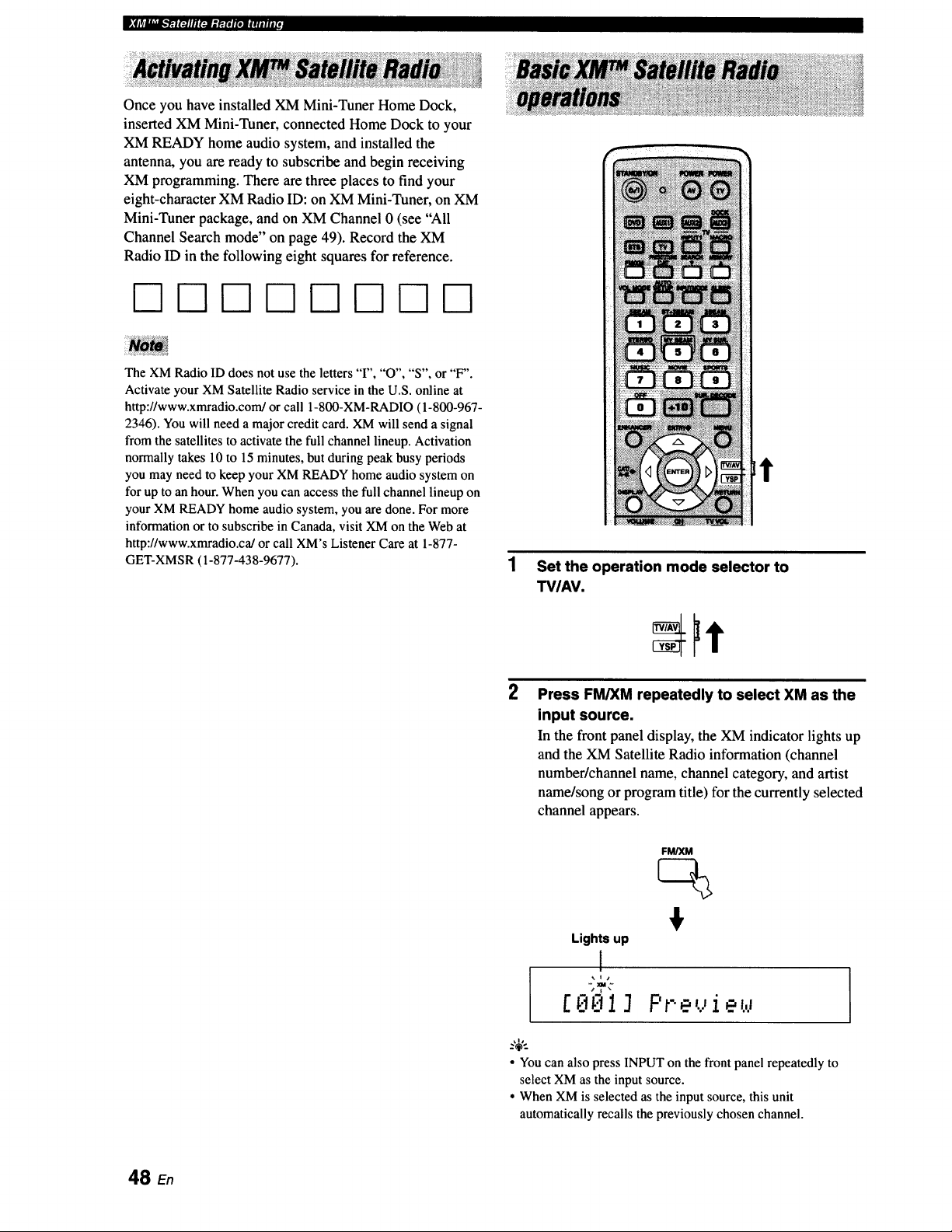
Once you have installed XM Mini-Tuner Home Dock,
inserted XM Mini-Tuner, connected Home Dock to your
XM READY home audio system, and installed the
antenna, you are ready to subscribe and begin receiving
XM programming. There are three places to find your
eight-character XM Radio ID: on XM Mini-Tuner, on XM
Mini-Tuner package, and on XM Channel 0 (see "All
Channel Search mode" on page 49). Record the XM
Radio ID in the following eight squares for reference.
The XM Radio ID does not use the letters "I", "O", "S", or "F".
Activate your XM Satellite Radio service in the U.S. online at
http://www.xmradio.com/or call 1-800-XM-RADIO (1-800-967-
2346). You will need a major credit card. XM will send a signal
from the satellites to activate the full channel lineup. Activation
normally takes 10 to 15 minutes, but during peak busy periods
you may need to keep your XM READY home audio system on
for up to an hour. When you can access the full channel lineup on
your XM READY home audio system, you are done. For more
information or to subscribe in Canada, visit XM on the Web at
http://www.xmradio.ca/or call XM's Listener Care at 1-877-
GET-XMSR (1-877-438-9677).
t
Set the operation mode selector to
TVIAV.
2
Press FM/XM repeatedly to select XM as the
input source.
In the front panel display, the XM indicator lights up
and the XM Satellite Radio information (channel
number/channel name, channel category, and artist
name/song or program title) for the currently selected
channel appears.
Lights up
I
[8 *13
FM/XM
F t" ...'i e X,l
• You can also press INPUT on the front panel repeatedly to
select XM as the input source.
• When XM is selected as the input source, this unit
automatically recalls the previously chosen channel.
48
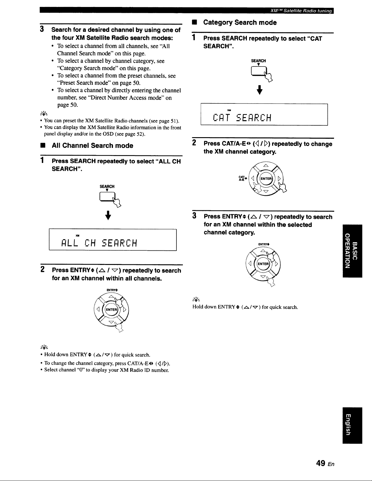
3 Search for a desired channel by using one of
the four XM Satellite Radio search modes:
• To select a channel from all channels, see "All
Channel Search mode" on this page.
• To select a channel by channel category, see
"Category Search mode" on this page.
• To select a channel from the preset channels, see
"Preset Search mode" on page 50.
• To select a channel by directly entering the channel
number, see "Direct Number Access mode" on
page 50.
..,_,..
• Youcan preset the XM Satellite Radio channels (see page 51).
• Youcan display the XM Satellite Radio information inthe front
panel display and/or in the OSD (see page 52).
• All Channel Search mode
1 Press SEARCH repeatedly to select "ALL CH
SEARCH".
SEARCH
+
I - I
I:ILL C:H 5EI:IRI:H
2 Press ENTRYI (A / _) repeatedly to search
for an XM channel within all channels.
l_rmY+
Sllrl__'_t_.'PTlr_llfli3gr.t+tr+]w.t#.n[,
• Category Search mode
1 Press SEARCH repeatedly to select "CAT
SEARCH",
SEARCH
+
XM
Im _ I
CI:IT _-,ENRC:H
2
Press CATIA-Eo (<_I [_) repeatedly to change
the XM channel category.
3
Press ENTRY© (A / _) repeatedly to search
for an XM channel within the selected
channel category,
ENTRYO
%o+
Hold down ENTRY# (A/_) for quick search.
• Hold down ENTRY_ ( .,_/';7 ) for quick search.
• To change the channelcategory, press CAT/A-EO (<1/D).
• Select channel "0" to display your XM Radio ID number.
49 E,
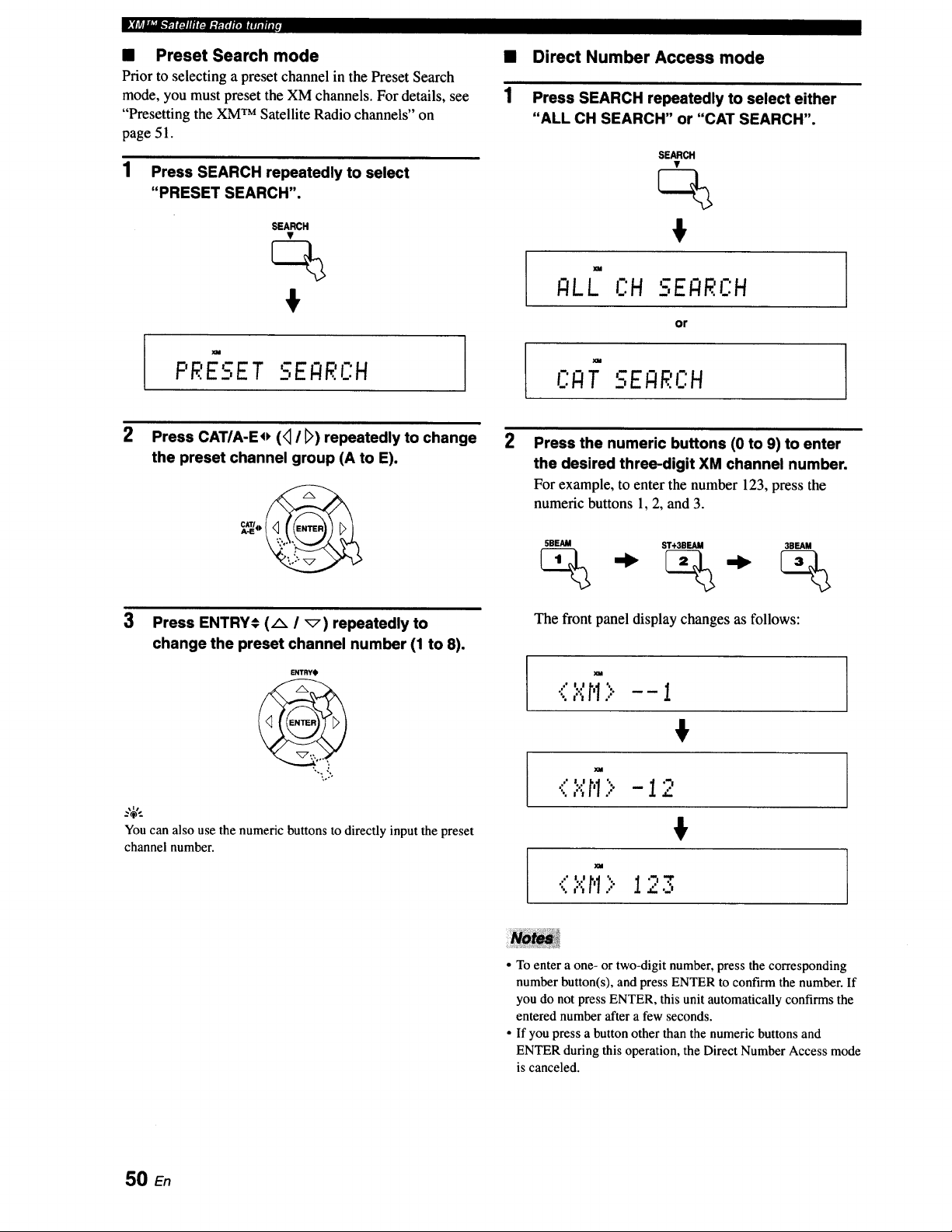
• Preset Search mode
Prior to selecting a preset channel in the Preset Search
mode, you must preset the XM channels. For details, see
"Presetting the XM TM Satellite Radio channels" on
page 51.
1 Press SEARCH repeatedly to select
"PRESET SEARCH".
SEARCH
$
PRESET SEI:IRL':H
2
1
Direct Number Access mode
Press SEARCH repeatedly to select either
"ALL CH SEARCH" or "CAT SEARCH".
SEARCH
$
XM
;ILL OH SE_RCH
or
t " I
CI.TIT SEI:IF:CH
2 Press the numeric buttons (0 to 9) to enter
the desired three-digit XM channel number.
For example, to enter the number 123, press the
numeric buttons l, 2, and 3.
Press CAT/A-Eo (<_I _) repeatedly to change
the preset channel group (A to E).
3
Press ENTRY# (A I _) repeatedly to
change the preset channel number (1 to 8).
ENTRYO
You can also use the numeric buttons to directly input the preset
channel number.
5BEAM ST+3BEAId 3BEAM
The front panel display changes as follows:
•(l.":r'1> -- i
€
<,"._,r,1> -12
!
" I
• To enter a one- or two-digit number, press the corresponding
number button(s), and press ENTER to confirm the number. If
you do not press ENTER, this unit automatically confirms the
entered number after a few seconds.
• If you press a button other than the numeric buttons and
ENTER during this operation, the Direct Number Access mode
is canceled.
50
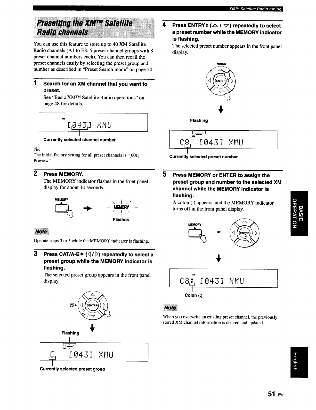
._jr:"""_l_lllR:Jl.'h'Rtt_f.,..,
You can use this feature to store up to 40 XM Satellite
Radio channels (A1 to E8:5 preset channel groups with 8
preset channel numbers each). You can then recall the
preset channels easily by selecting the preset group and
number as described in "Preset Search mode" on page 50.
1
Search for an XM channel that you want to
preset.
See "Basic XM TM Satellite Radio operations" on
page 48 for details.
m
[ _] ""r'lu
Currently selected channel number
_,$,,_
The initial factory setting for all preset channels is "[001]
Preview".
2 Press MEMORY.
The MEMORY indicator flashes in the front panel
display for about 10 seconds.
MEMORY i .."°
_(_ '_ ..... _ .....
"°'" i "'""
Flashes
Operate steps 3 to 5 while the MEMORY indicator is flashing.
3
Press CAT/A-Eo (<_I D) repeatedly to select a
preset group while the MEMORY indicator is
flashing.
The selected preset group appears in the front panel
display.
Flashing
[ kt4._':] ,...,_ILi
Currently selected preset group
4
Press ENTRY_ (A I _) repeatedly to select
a preset number while the MEMORY indicator
is flashing.
The selected preset number appears in the front panel
display.
B_TRYt
Flashing
-- II It
i_': [ _t43 J It",flu
Currently selected preset number
5
Press MEMORY or ENTER to assign the
preset group and number to the selected XM
channel while the MEMORY indicator is
flashing.
A colon (:) appears, and the MEMORY indicator
turns off in the front panel display.
XM
L'" [E143J
Colon (:1
I ! I
It...,_1LI
When you overwrite an existing preset channel, the previously
stored XM channel information is cleared and updated.
51 En
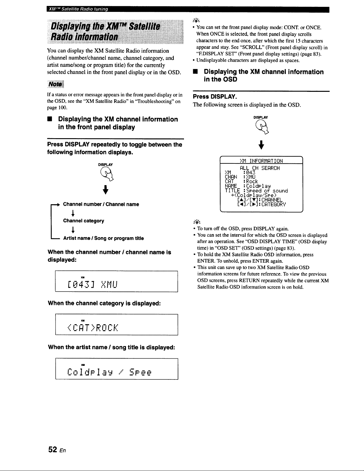
D." f tr.J"_"__'_El i'_] lll FJl l l_[i jl'i]l l l l i l l l l _
You can display the XM Satellite Radio information
(channel number/channel name, channel category, and
artist name/song or program title) for the currently
selected channel in the front panel display or in the OSD.
• You can set the front panel display mode: CONT. or ONCE.
When ONCE is selected, the front panel display scrolls
characters to the end once, after which the first 15 characters
appear and stay. See "SCROLL" (Front panel display scroll) in
"EDISPLAY SET" (Front panel display settings) (page 83).
• Undisplayable characters are displayed as spaces.
• Displaying the XM channel information
in the OSD
If a status or error message appears in the front panel display or in
the OSD, see the "XM Satellite Radio" in "Troubleshooting" on
page 100.
• Displaying the XM channel information
in the front panel display
Press DISPLAY repeatedly to toggle between the
following information displays,
DISPLAY
_ hannel number / Channel name
Channel category
Artist name / Song or program title
When the channel number ! channel name is
displayed:
XM
. ","hillC;143 ] ..,,,.
Press DISPLAY.
The following screen is displayed in the OSD.
DISPLAY
XM INFORMATION
ALL CH SEARCH
XM :043
CHAN :XMU
CAT :Rook
NAME :ColdPla_
TITLE :SPeed o_ sound
÷(ColdPla_/SPe)
[I]/[v]:CHANNEL
[_]/[_]:CATEGORV
• To turn off the OSD, press DISPLAY again.
• You can set the interval for which the OSD screen is displayed
after an operation. See "OSD DISPLAY TIME" (OSD display
time) in "OSD SET" (OSD settings) (page 83).
• To hold the XM Satellite Radio OSD information, press
ENTER. To unhold, press ENTER again.
• This unit can save up to two XM Satellite Radio OSD
information screens for future reference. To view the previous
OSD screens, press RETURN repeatedly while the current XM
Satellite Radio OSD information screen is on hold.
When the channel category is displayed:
m
..',CA T >ROCK
When the artist name I song title is displayed:
L':O1dP 1 ...' SPee
52 E.
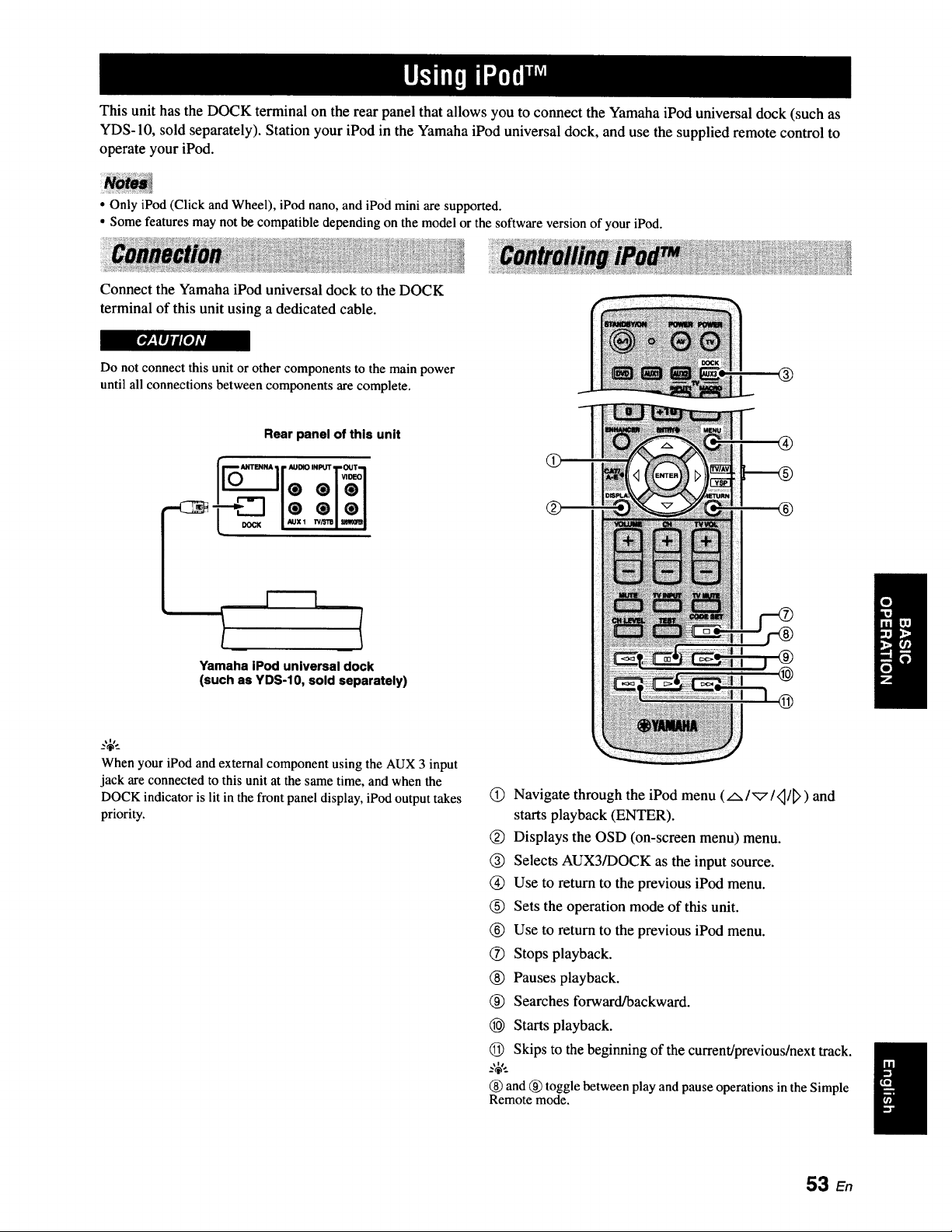
This unit has the DOCK terminal on the rear panel that allows you to connect the Yamaha iPod universal dock (such as
YDS-10, sold separately). Station your iPod in the Yamaha iPod universal dock, and use the supplied remote control to
operate your iPod.
• Only iPod (Click and Wheel), iPod nano, and iPod mini are supported.
• Some features may not be compatible depending on the model or the software version of your iPod.
Connect the Yamaha iPod universal dock to the DOCK
terminal of this unit using a dedicated cable.
[I#_,lfill P/_
Do not connect this unit or other components to the main power
until all connections between components are complete.
Rear panel of this unit
ANTENNA I r AUDIO INPI_I"_I"OUT-_I
:111
DOCK / Auxl n_z_I _1
Yamaha iPod universal dock
(such as YDS-10, sold separately)
Q
.,_,.
When your iPod and external component using the AUX 3 input
jack are connected to this unit at the same time, and when the
DOCK indicator is lit in the front panel display, iPod output takes
priority.
(_) Navigate through the iPod menu (AI'_I,_/_>) and
starts playback (ENTER).
(_) Displays the OSD (on-screen menu) menu.
(_) Selects AUX3/DOCK as the input source.
(_) Use to return to the previous iPod menu.
(_) Sets the operation mode of this unit.
(_) Use to return to the previous iPod menu.
Stops playback.
(_) Pauses playback.
(_) Searches forward/backward.
_) Starts playback.
(_) Skips to the beginning of the current/previous/next track.
_%',.
(_) and (_)toggle between play and pause operations in the Simple
Remote mode.
53 En
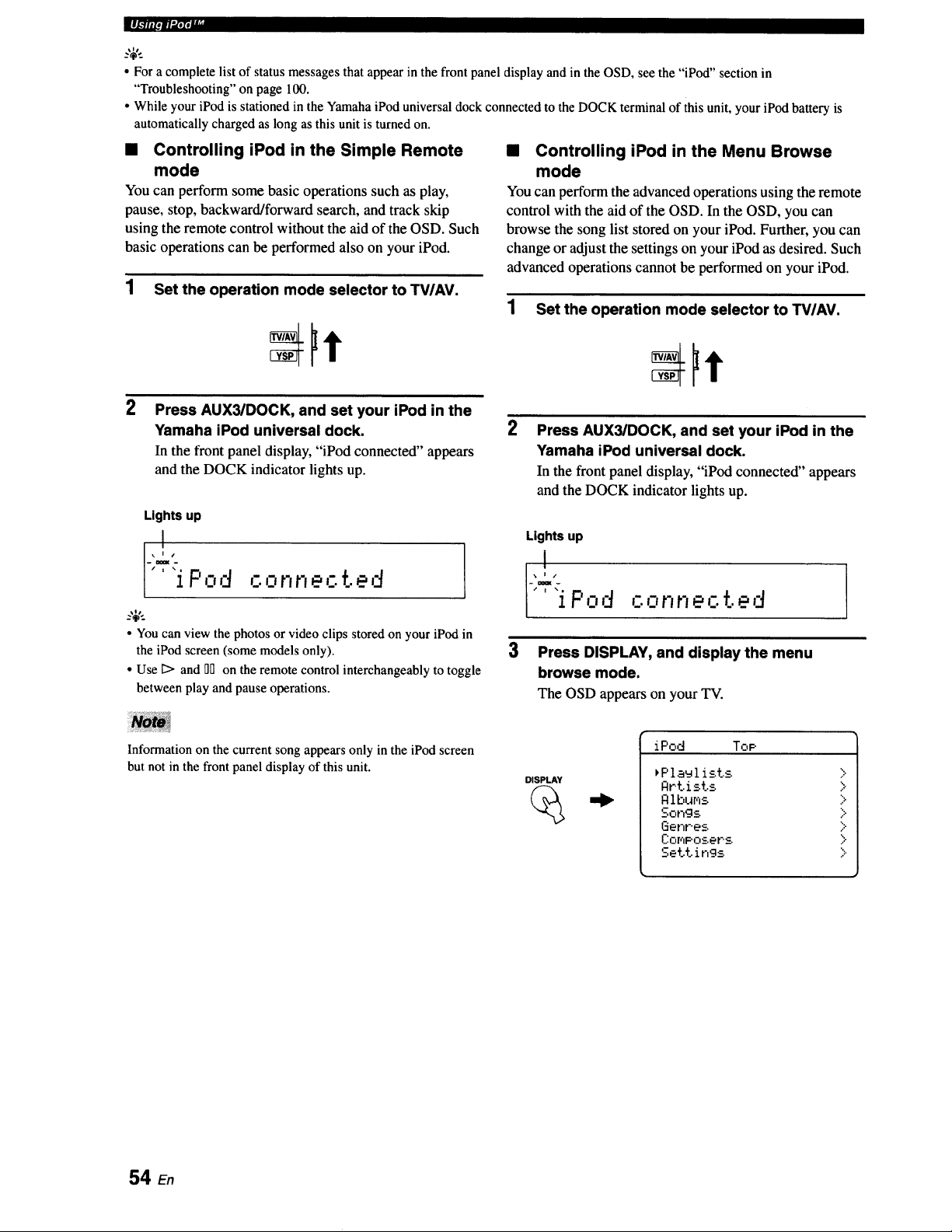
",l-'-,-|li_lf I
• For a complete list of status messagesthat appearin the front panel display and in theOSD, see the "iPod" section in
"Troubleshooting"on page 100.
• While your iPod is stationed in the YamahaiPod universaldock connectedto the DOCK terminal of this unit, your iPod batteryis
automaticallycharged as long as this unit is turned on.
• Controlling iPod in the Simple Remote
mode
You can perform some basic operations such as play,
pause, stop, backward/forward search, and track skip
using the remote control without the aid of the OSD. Such
basic operations can be performed also on your iPod.
1 Set the operation mode selector to TV/AV.
2
Press AUX3/DOCK, and set your iPod in the
Yamaha iPod universal dock.
In the front panel display, "iPod connected" appears
and the DOCK indicator lights up.
Lights up
_'L2.
['*'i P,:,d ,_-.or,r,ected
_.'&.
• You can view the photosor video clips storedon your iPod in
the iPod screen(some modelsonly).
• Use Ii> and _Don the remotecontrol interchangeablyto toggle
between play and pause operations.
• Controlling iPod in the Menu Browse
mode
You can perform the advanced operations using the remote
control with the aid of the OSD. In the OSD, you can
browse the song list stored on your iPod. Further, you can
change or adjust the settings on your iPod as desired. Such
advanced operations cannot be performed on your iPod.
1 Set the operation mode selector to TVIAV.
2
Press AUX3/DOCK, and set your iPod in the
Yamaha iPod universal dock.
In the front panel display, "iPod connected" appears
and the DOCK indicator lights up.
Lights up
:L?.
[" iP,:,d ,.-.onnecte,'
3
Press DISPLAY, and display the menu
browse mode.
The OSD appearson yourTV.
Information on the current song appears only in the iPod screen
but not in the front panel display of this unit.
DISPLAY
iPod Top
_Plaulist.s
Artists
Rlbums
Songs
Genres.
ComPosers
Settings
>
>
>
>
>
>
>
54 En
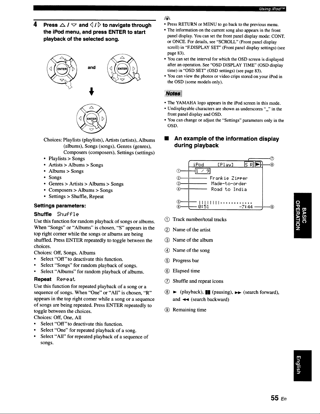
4 Press _ I _ and <11t> to navigate through
the iPod menu, and press ENTER to start
playback of the selected song.
and
.....
!
Choices: Playlists (playlists), Artists (artists), Albums
(albums), Songs (songs), Genres (genres),
Composers (composers), Settings (settings)
• Playlists > Songs
• Artists > Albums > Songs
• Albums > Songs
• Songs
• Genres > Artists > Albums > Songs
• Composers > Albums > Songs
• Settings > Shuffle, Repeat
Settings parameters:
Shuffle ShLff't:'l e
Use this function for random playback of songs or albums.
When "Songs" or "Albums" is chosen, "S" appears in the
top right comer while the songs or albums are being
shuffled. Press ENTER repeatedly to toggle between the
choices.
Choices: Off, Songs, Albums
• Select "Off'to deactivate this function.
• Select "Songs" for random playback of songs.
• Select "Albums" for random playback of albums.
Repeat RePeat
Use this function for repeated playback of a song or a
sequence of songs. When "One" or "All" is chosen, "R"
appears in the top right comer while a song or a sequence
of songs are being repeated. Press ENTER repeatedly to
toggle between the choices.
Choices: Off, One, All
• Select "Off'to deactivate this function.
• Select "One" for repeated playback of a song.
• Select "All" for repeated playback of a sequence of
songs.
.l.llll.m.,,ir,,, I
• Press RETURN or MENU to go back to the previous menu.
• The informationon the current song also appears in the front
panel display.Youcan set the front panel display mode: CONT.
or ONCE. For details, see "SCROLL" (Front panel display
scroll) in "F.DISPLAYSET" (Front panel display settings) (see
page 83).
• You can set the interval for which the OSD screen is displayed
after an operation. See "OSD DISPLAYTIME" (OSD display
time) in "OSD SET' (OSD settings) (see page 83).
• Youcan view the photos or video crips stored on your iPod in
the OSD (some models only).
• The YAMAHA logo appears in the iPod screen in this mode.
• Undisplayable characters are shown as underscores "_" in the
front panel display and OSD.
• You can change or adjust the "Settings" parameters only in the
OSD.
An example of the information display
during playback
[ iF'od EF'la _, brRIl .
_Frahk ie .-iF.Per.
® Made-t.o-oPdet-
® I Road to India
I
(S) Track number/total tracks
(_) Name of the artist
® Name of the album
(_) Name of the song
® Progress bar
® Elapsed time
(_ Shuffle and repeat icons
®
®
--@
(playback), II (pausing), _w, (search forward),
and ,_1 (search backward)
® Remaining time
55 En
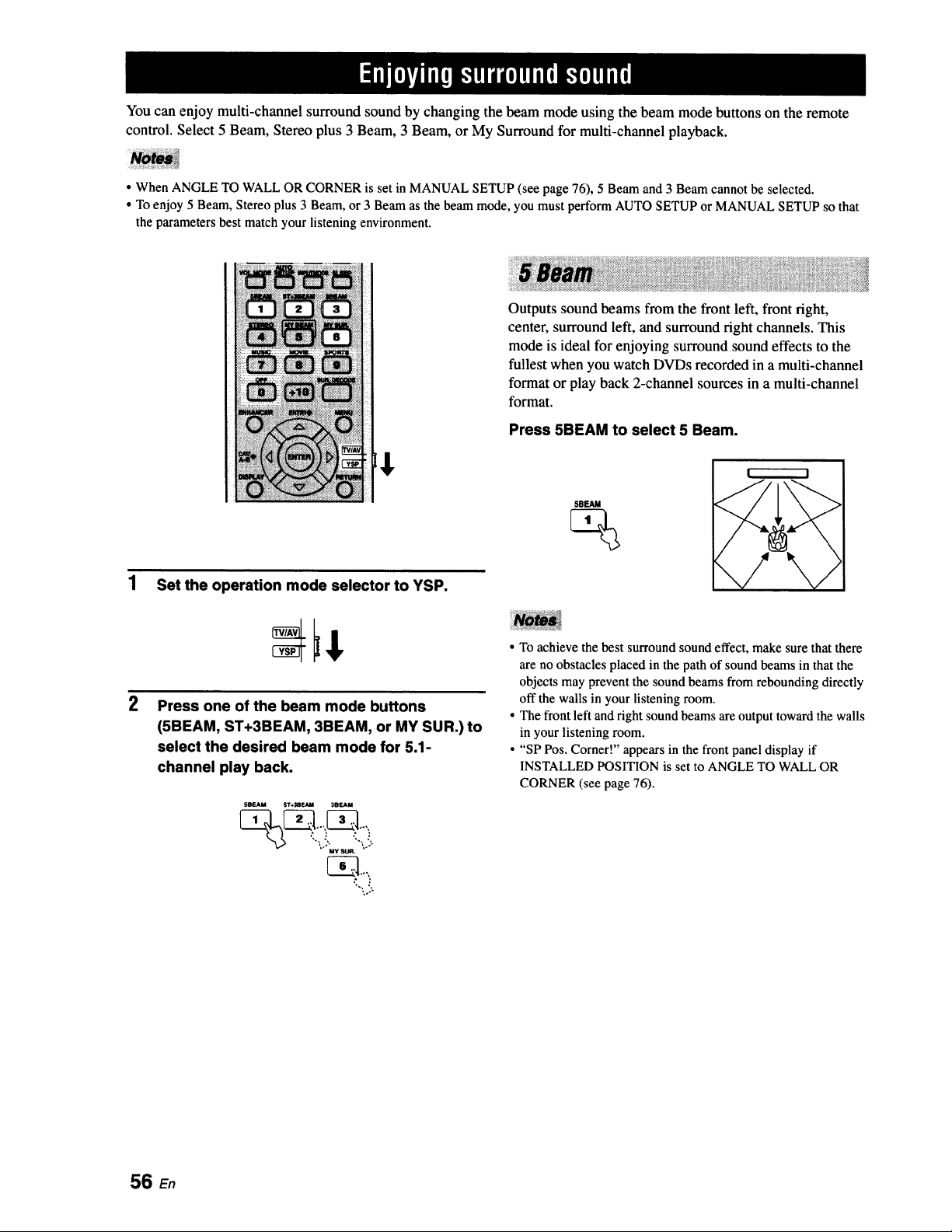
You can enjoy multi-channel surround sound by changing the beam mode using the beam mode buttons on the remote
control. Select 5 Beam, Stereo plus 3 Beam, 3 Beam, or My Surround for multi-channel playback.
• When ANGLE TO WALL OR CORNER is set in MANUAL SETUP (see page 76), 5 Beam and 3 Beam cannot be selected.
• To enjoy 5 Beam, Stereo plus 3 Beam, or 3 Beam as the beam mode, you must perform AUTO SETUP or MANUAL SETUP so that
the parameters best match your listening environment.
1 Set the operation mode selector to YSP.
2
Press one of the beam mode buttons
(5BEAM, ST+3BEAM, 3BEAM, or MY SUR.) to
select the desired beam mode for 5.1-
channel play back.
5BEAM _r_-,_EAM 3BEAM
%
"'\ _'. _'\_:
MY
..,.
"-\::.
Outputs sound beams from the front left, front right,
center, surround left, and surround right channels. This
mode is ideal for enjoying surround sound effects to the
fullest when you watch DVDs recorded in a multi-channel
format or play back 2-channel sources in a multi-channel
format.
Press 5BEAM to select 5 Beam.
5SEAM
%
I
• To achieve the best surround sound effect, make sure that there
are no obstacles placed in the path of sound beams in that the
objects may prevent the sound beams from rebounding directly
off the walls in your listening room.
• The front left and right sound beams are output toward the walls
in your listening room.
• "SP Pos. Corner!" appears in the front panel display if
INSTALLED POSITION is set to ANGLE TO WALL OR
CORNER (see page 76).
56 En
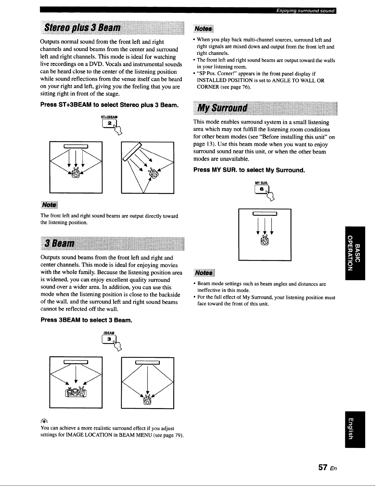
_(|_E_JrllllOB."illlil[_]lllfOIl.yoJIIIfl
Outputs normal sound from the front left and fight
channels and sound beams from the center and surround
left and fight channels. This mode is ideal for watching
live recordings on a DVD. Vocals and instrumental sounds
can be heard close to the center of the listening position
while sound reflections from the venue itself can be heard
on your fight and left, giving you the feeling that you are
sitting fight in front of the stage.
Press ST+3BEAM to select Stereo plus 3 Beam.
• When you play back multi-channel sources, surround left and
right signals are mixed down and output from the front left and
right channels.
• The front left and right sound beams are output toward the walls
in your listening room.
• "SP Pos. Corner!" appears in the front panel display if
INSTALLED POSITION is set to ANGLE TO WALL OR
CORNER (see page 76).
This mode enables surround system in a small listening
area which may not fulfill the listening room conditions
for other beam modes (see "Before installing this unit" on
page 13). Use this beam mode when you want to enjoy
surround sound near this unit, or when the other beam
modes are unavailable.
Press MY SUR. to select My Surround.
MY SUR.
%
The front left and right sound beams are output directly toward
the listening position.
Outputs sound beams from the front left and fight and
center channels. This mode is ideal for enjoying movies
with the whole family. Because the listening position area
is widened, you can enjoy excellent quality surround
sound over a wider area. In addition, you can use this
mode when the listening position is close to the backside
of the wall, and the surround left and fight sound beams
cannot be reflected off the wall.
Press 3BEAM to select 3 Beam.
3BEAM
! I
! I
• Beam mode settings such as beam angles and distances are
ineffective in this mode.
• For the full effect of My Surround, your listening position must
face toward the front of this unit.
_.'_',_
You can achieve a more realistic surround effect if you adjust
settings for IMAGE LOCATION in BEAM MENU (see page 79).
57 E.
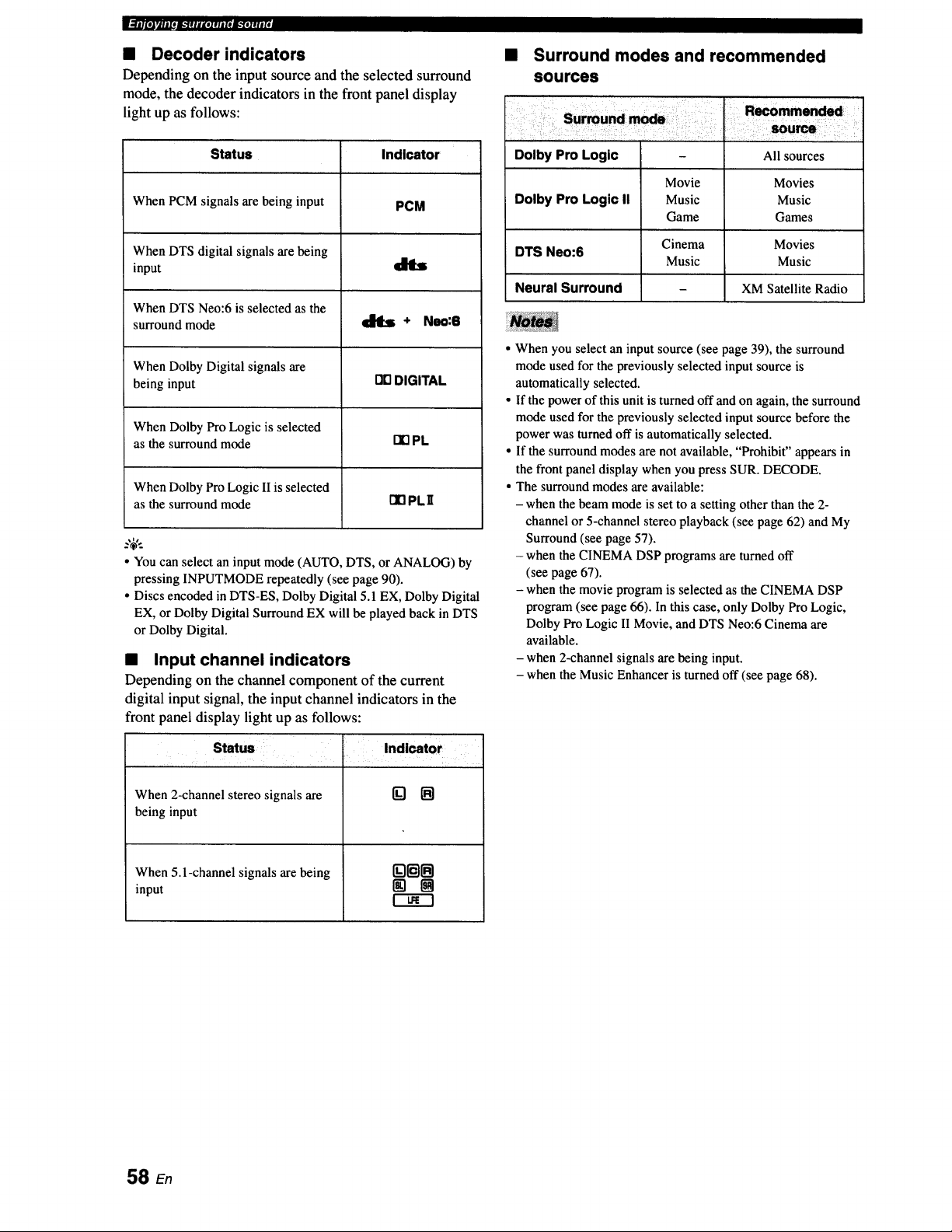
m.TT_l_eJk"l;l_telFlaloJ_allllId
• Decoder indicators
Depending on the input source and the selected surround
mode, the decoder indicators in the front panel display
light up as follows:
Status Indicator
When PCM signals are being input PCM
When DTS digital signals are being
input t1_
When DTS Neo:6 is selected as the
surround mode _ + Neo:6
When Dolby Digital signals are
being input I_ DIGITAL
When Dolby Pro Logic is selected
as the surround mode I1"1PL
When Dolby Pro Logic II is selected
as the surround mode [I] PL II
..,$,.
• You can select an input mode (AUTO, DTS, or ANALOG) by
pressing INPUTMODE repeatedly (see page 90).
• Discs encoded in DTS-ES, Dolby Digital 5.1 EX, Dolby Digital
EX, or Dolby Digital Surround EX will be played back in DTS
or Dolby Digital.
• Input channel indicators
Depending on the channel component of the current
digital input signal, the input channel indicators in the
front panel display light up as follows:
Status
When 2-channel stereo signals are
being input
When 5. l-channel signals are being
input
Indicator
B
Surround modes and recommended
sources
Dolby Pro Logic - All sources
Movie Movies
Dolby Pro Logic II Music Music
Game Games
Cinema Movies
DTS Neo:6
Music Music
Neural Surround - XM Satellite Radio
When you select an input source (see page 39), the surround
mode used for the previously selected input source is
automatically selected.
If the power of this unit is turned off and on again, the surround
mode used for the previously selected input source before the
power was turned off is automatically selected.
If the surround modes are not available, "Prohibit" appears in
the front panel display when you press SUR. DECODE.
The surround modes are available:
- when the beam mode is set to a setting other than the 2-
channel or 5-channel stereo playback (see page 62) and My
Surround (see page 57).
- when the CINEMA DSP programs are turned off
(see page 67).
- when the movie program is selected as the CINEMA DSP
program (see page 66). In this case, only Dolby Pro Logic,
Dolby Pro Logic II Movie, and DTS Neo:6 Cinema are
available.
- when 2-channel signals are being input.
- when the Music Enhancer is turned off (see page 68).
58 en
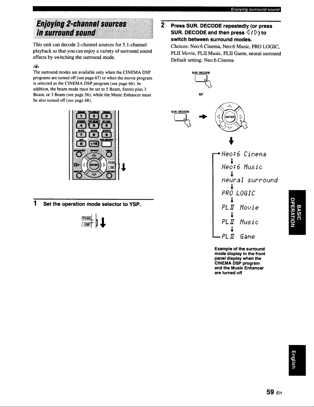
_|_lrJlI[Om."IlIII[OIIIIItIL"[O]III[I
This unit can decode 2-channel sources for 5. l-channel
playback so that you can enjoy a variety of surround sound
effects by switching the surround mode.
The surround modes are availableonly when the CINEMA DSP
programs are turnedoff (see page 67) or when the movie program
is selectedas the CINEMA DSP program (see page 66). In
addition, the beam mode must be set to 5 Beam, Stereo plus 3
Beam,or 3 Beam (see page 56), while the Music Enhancer must
be also turned off (see page 68).
1 Set the operation mode selector to YSP.
2
Press SUR. DECODE repeatedly (or press
SUR. DECODE and then press <_/ [_) to
switch between surround modes.
Choices: Neo:6 Cinema, Neo:6 Music, PRO LOGIC,
PLII Movie, PLII Music, PLII Game, neural surround
Default setting: Neo:6 Cinema
SUR. DECODE
or
SUR, DECODE
--_Neo:6 Cinema
Neo:6 Music
neut'al surround
PRO LOGIC
PL E t'1ouJ e
PL E t'lus i c
PL E GaF,e
Example of the surround
mode display in the front
panel display when the
CINEMA DSP program
and the Music Enhancer
are turned off
59 En
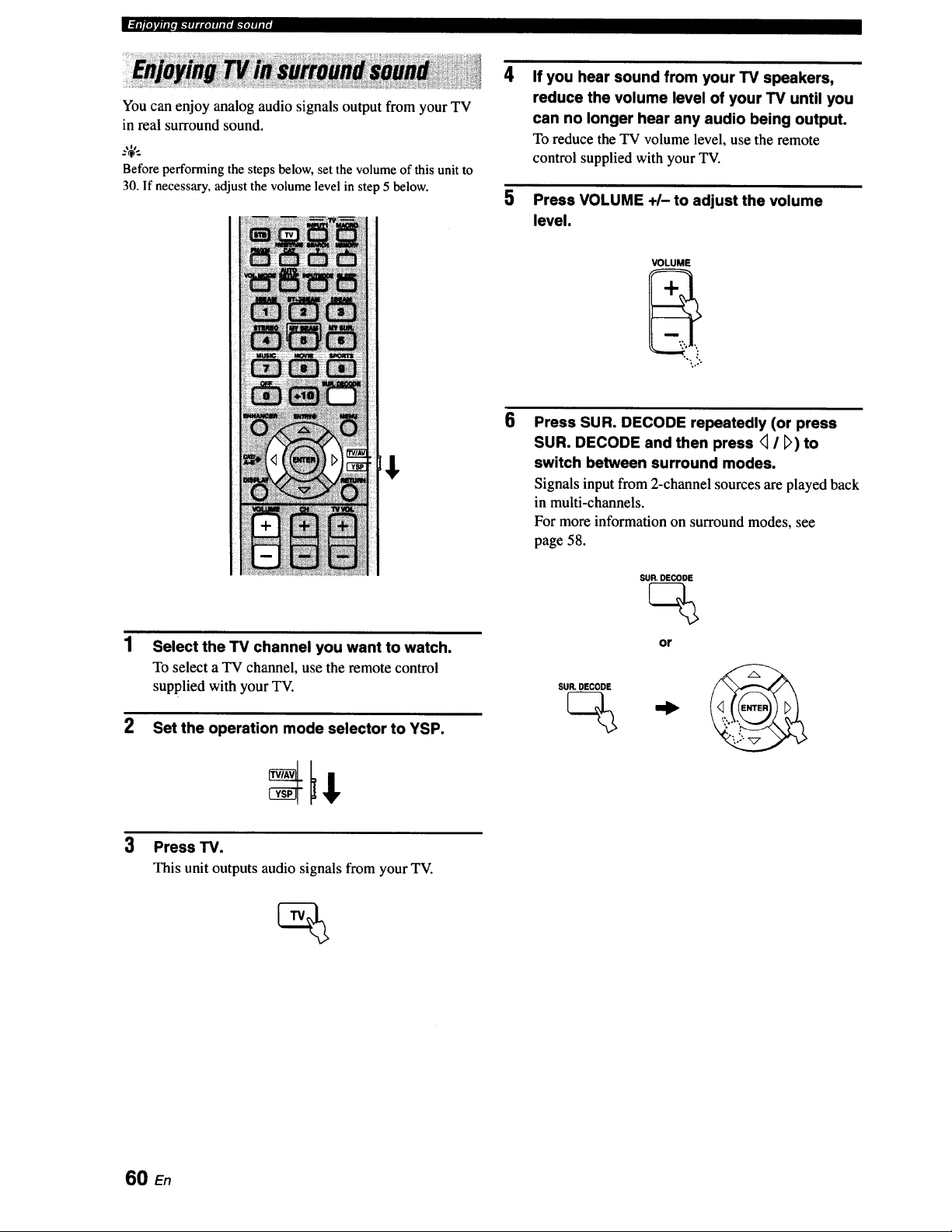
_]i__l[lJrllllOl_"llldKOlllllel_.Ylllll[I
You can enjoy analog audio signals output from your TV
in real surround sound.
Before performing the steps below,set thevolume of this unit to
30. If necessary,adjust the volume level in step 5 below.
4
If you hear sound from your TV speakers,
reduce the volume level of your TV until you
can no longer hear any audio being output.
To reduce the TV volume level, use the remote
control supplied with your TV.
5 Press VOLUME +1- to adjust the volume
level.
VOLUME
E$
Select the TV channel you want to watch.
To select aTV channel,usethe remote control
supplied with your TV.
2 Set the operation mode selector to YSP.
6
Press SUR. DECODE repeatedly (or press
SUR. DECODE and then press <_I _>)to
switch between surround modes.
Signals input from 2-channel sources are played back
in multi-channels.
For more information on surround modes, see
page 58.
SUR. DECODE
SUR. DECODE
or
3
Press TV.
This unit outputs audio signals from your TV.
60 En
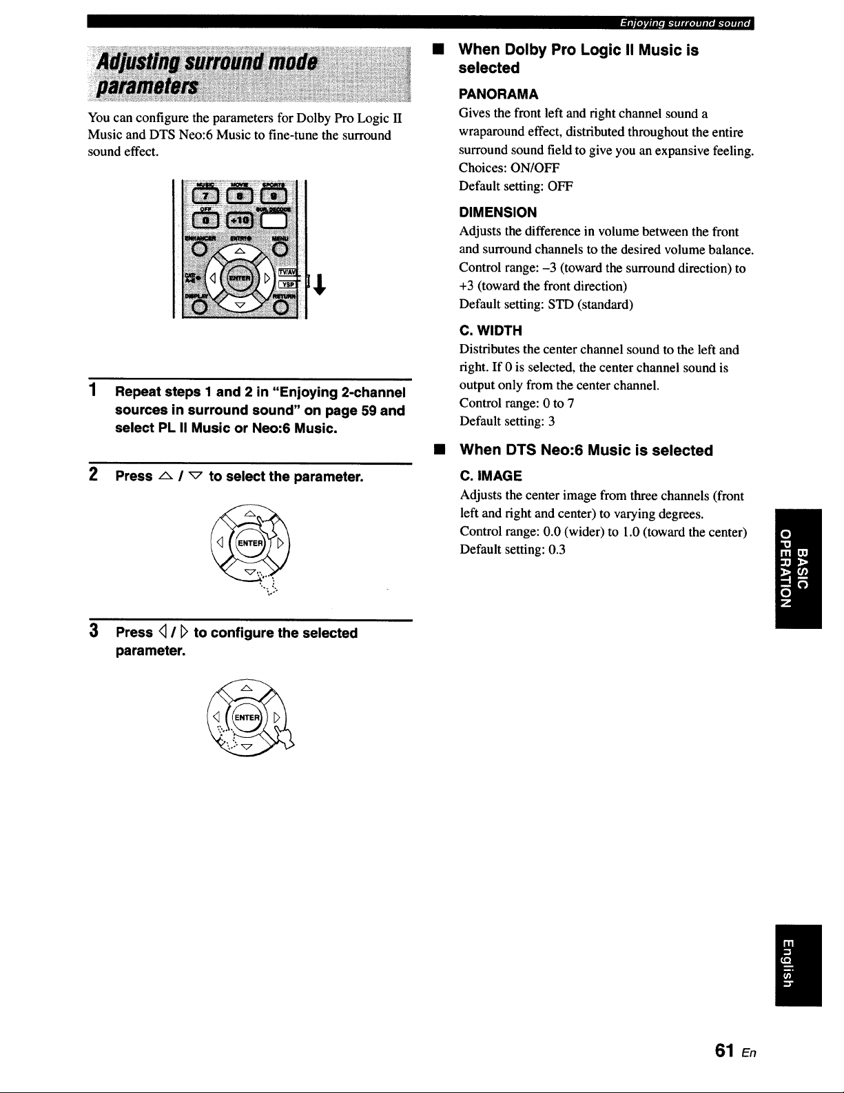
You can configure the parameters for Dolby Pro Logic II
Music and DTS Neo:6 Music to fine-tune the surround
sound effect.
1 Repeat steps 1 and 2 in "Enjoying 2-channel
sources in surround sound" on page 59 and
select PL II Music or Neo:6 Music.
2
Press A i _ to select the parameter.
3 Press <1/ D to configure the selected
parameter.
ifllt_a'Jt,t'm,.'_!tltDI!l.td'm."t.lfl|Id
When Dolby Pro Logic II Music is
selected
PANORAMA
Gives the front left and fight channel sound a
wraparound effect, distributed throughout the entire
surround sound field to give you an expansive feeling.
Choices: ON/OFF
Default setting: OFF
DIMENSION
Adjusts the difference in volume between the front
and surround channels to the desired volume balance.
Control range: -3 (toward the surround direction) to
+3 (toward the front direction)
Default setting: STD (standard)
C. WIDTH
Distributes the center channel sound to the left and
right. If 0 is selected, the center channel sound is
output only from the center channel.
Control range: 0 to 7
Default setting: 3
• When DTS Neo:6 Music is selected
C. IMAGE
Adjusts the center image from three channels (front
left and right and center) to varying degrees.
Control range: 0.0 (wider) to 1.0 (toward the center)
Default setting: 0.3
61 En
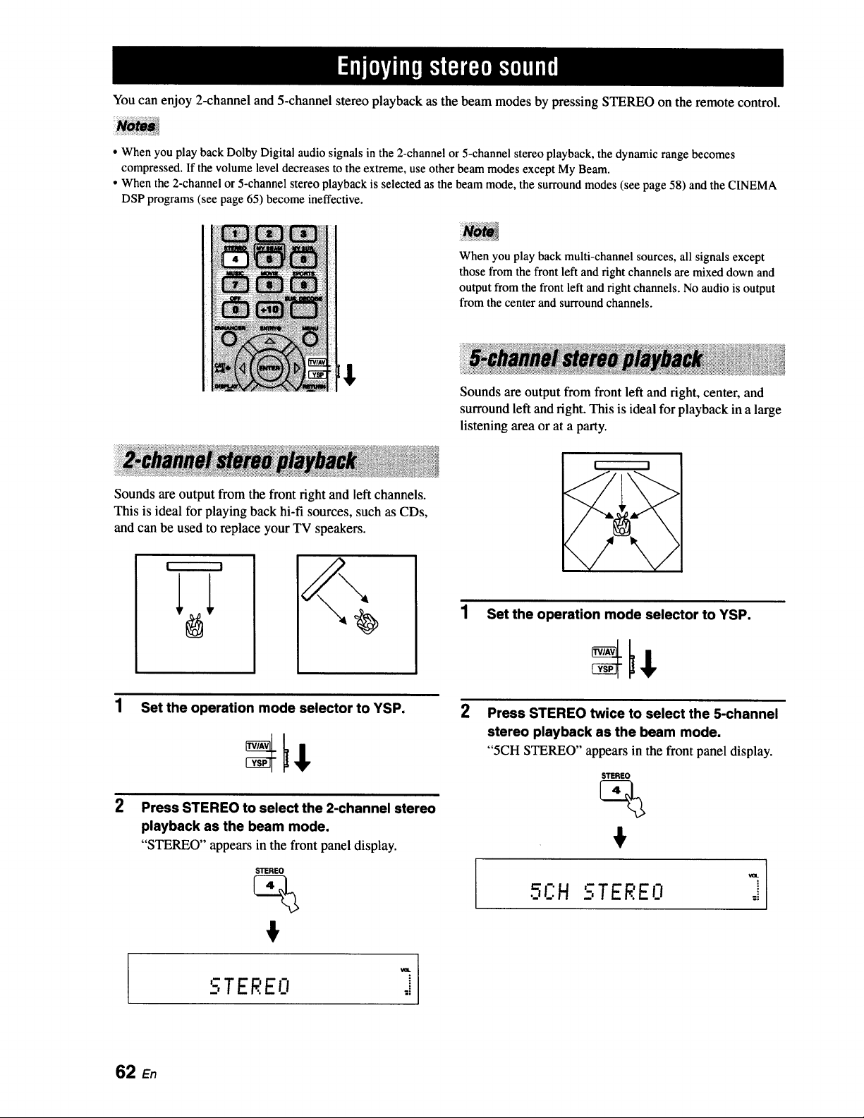
You can enjoy 2-channel and 5-channel stereo playback as the beam modes by pressing STEREO on the remote control.
• When you play back Dolby Digital audio signals in the 2-channel or 5-channel stereo playback, the dynamic range becomes
compressed. If the volume level decreases to the extreme, use other beam modes except My Beam.
• When the 2-channel or 5-channel stereo playback is selected as the beam mode, the surround modes (see page 58) and the CINEMA
DSP programs (see page 65) become ineffective.
When you play back multi-channel sources, all signals except
those from the front left and right channels are mixed down and
output from the front left and right channels. No audio is output
from the center and surround channels.
Sounds are output from front left and fight, center, and
surround left and fight. This is ideal for playback in a large
listening area or at a party.
Sounds are output from the front fight and left channels.
This is ideal for playing back hi-fi sources, such as CDs,
and can be used to replace your TV speakers.
F------'-I
2
Set the operation mode selector to YSP.
Press STEREO to select the 2-channel stereo
playback as the beam mode.
"STEREO" appears in the front panel display.
STEREO
1 Set the operation mode selector to YSP.
2
Press STEREO twice to select the 5-channel
stereo playback as the beam mode.
"5CH STEREO" appears in the front panel display.
STEREO
_ R Im• F:H -,TEREO
'-iTF .'FIi
62
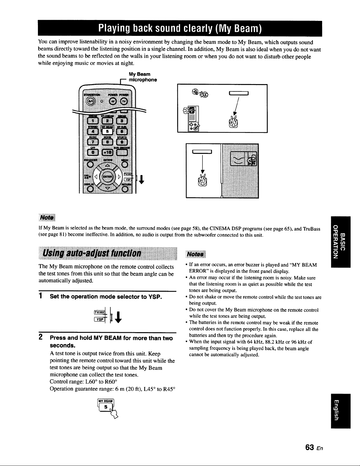
You can improve listenability in a noisy environment by changing the beam mode to My Beam, which outputs sound
beams directly toward the listening position in a single channel. In addition, My Beam is also ideal when you do not want
the sound beams to be reflected on the walls in your listening room or when you do not want to disturb other people
while enjoying music or movies at night.
My Beam
microphone
If My Beam is selected as the beam mode, the surround modes (see page 58), the CINEMA DSP programs (see page 65), and TruBass
(see page 81) become ineffective. In addition, no audio is output from the subwoofer connected to this unit.
The My Beam microphone on the remote control collects
the test tones from this unit so that the beam angle can be
automatically adjusted.
1 Set the operation mode selector to YSP.
2
Press and hold MY BEAM for more than two
seconds.
A test tone is output twice from this unit. Keep
pointing the remote control toward this unit while the
test tones are being output so that the My Beam
microphone can collect the test tones.
Control range: L60 ° to R60 °
Operation guarantee range: 6 m (20 ft), L45 ° to R45 °
• If an error occurs, an error buzzer is played and "MY BEAM
ERROR" is displayed in the front panel display.
• An error may occur if the listening room is noisy. Make sure
that the listening room is as quiet as possible while the test
tones are being output.
• Do not shake or move the remote control while the test tones are
being output.
• Do not cover the My Beam microphone on the remote control
while the test tones are being output.
• The batteries in the remote control may be weak if the remote
control does not function properly. In this case, replace all the
batteries and then try the procedure again.
• When the input signal with 64 kHz, 88.2 kHz or 96 kHz of
sampling frequency is being played back, the beam angle
cannot be automatically adjusted.
63 En
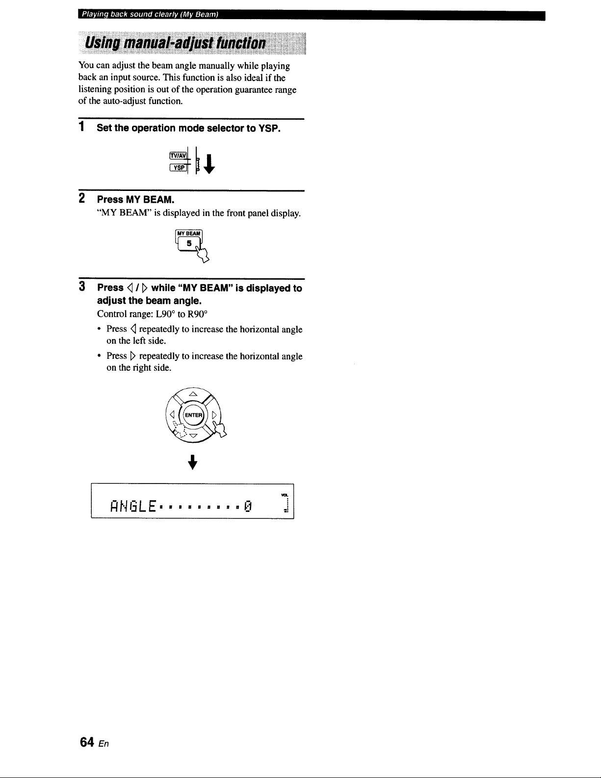
You can adjust the beam angle manually while playing
back an input source. This function is also ideal if the
listening position is out of the operation guarantee range
of the auto-adjust function.
1 Set the operation mode selector to YSP.
2
Press MY BEAM.
"MY BEAM" is displayed in the front panel display.
Press _ / [_ while "MY BEAM" is displayed to
adjust the beam angle.
Control range: L90 ° to R90°
• Press <_repeatedly to increase the horizontal angle
on the left side.
° Press D' repeatedly to increase the horizontal angle
on the right side.
64 E,
This unit is equipped with a variety of precise digital decoders that allow you to enjoy multi-channel playback from
stereo or multi-channel sources. This unit is also equipped with a Yamaha CINEMA DSP (digital sound field processing)
chip containing several sound field programs used to enhance your playback experience. Most of the CINEMA DSP
programs are precise digital recreations of actual acoustic environments found in famous concert halls, music venues, and
movie theaters.
The Yamaha CINEMA DSP programs are compatible with all Dolby Digital, DTS, and Dolby Surround sources.
Choose a CINEMA DSP program based on your listening preference and do not purely rely on the name of the CINEMA DSP program
itself.
• What is a sound field?
A significant factor that creates the rich, full tones of a live instrument is the multiple reflections from the walls of the
room. In addition to making the sound live, these reflections enable the listener to tell where the player is situated as well
as the size and shape of the room in which the listener is sitting.
• Elements of a sound field
In any environment, there are two distinct types of sound reflections combined with the direct sound coming straight to
our ears from the player's instrument to make up the sound field.
Early reflections
Reflected sounds reach our ears extremely rapidly (50 ms to 80 ms after the direct sound) after reflecting from one
surface only (from the ceiling or the wall, for example). Early reflections help add clarity to the direct sound.
Reverberations
These are caused by reflections from more than one surface (i.e., wall, ceiling, the back of the room, etc.) so numerous
that they merge together to form a continuous sonic afterglow. They are non-directional and lessen the clarity of the direct
sound.
Direct sound, early reflections, and subsequent reverberations all together help us determine the subjective size and shape
of the room, and it is this information that the digital sound field processor reproduces in order to create the sound fields.
With the appropriate early reflections and subsequent reverberations in your listening room, you can create your own
listening environment. The acoustics in your room could be changed to those of a concert hall, a dance floor, or a
listening room of virtually any size at all. This ability to create sound fields at will is exactly what Yamaha has done with
the CINEMA DSP technology.
65 En
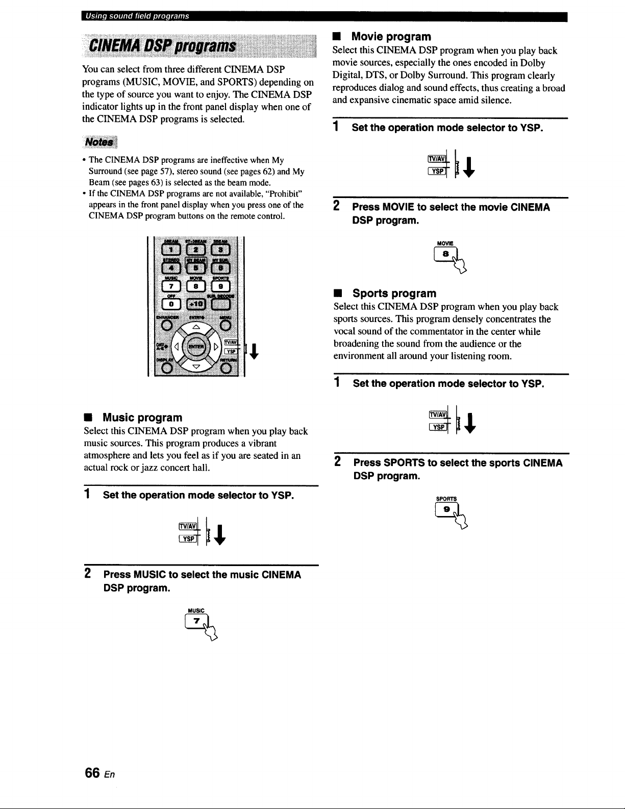
You can select from three different CINEMA DSP
programs (MUSIC, MOVIE, and SPORTS) depending on
the type of source you want to enjoy. The CINEMA DSP
indicator lights up in the front panel display when one of
the CINEMA DSP programs is selected.
• The CINEMA DSP programs are ineffective when My
Surround (see page 57), stereo sound (see pages 62) and My
Beam (see pages 63) is selected as the beam mode.
• If the CINEMA DSP programs are not available, "Prohibit"
appears in the front panel display when you press one of the
CINEMA DSP program buttons on the remote control.
t
• Music program
Select this CINEMA DSP program when you play back
music sources. This program produces a vibrant
atmosphere and lets you feel as if you are seated in an
actual rock or jazz concert hall.
1 Set the operation mode selector to YSP.
• Movie program
Select this CINEMA DSP program when you play back
movie sources, especially the ones encoded in Dolby
Digital, DTS, or Dolby Surround. This program clearly
reproduces dialog and sound effects, thus creating a broad
and expansive cinematic space amid silence.
1 Set the operation mode selector to YSP.
2 Press MOVIE to select the movie CINEMA
DSP program.
MOVIE
• Sports program
Select this CINEMA DSP program when you play back
sports sources. This program densely concentrates the
vocal sound of the commentator in the center while
broadening the sound from the audience or the
environment all around your listening room.
1 Set the operation mode selector to YSP.
2
Press SPORTS to select the sports CINEMA
DSP program.
SPORTS
2
Press MUSIC to select the music CINEMA
DSP program.
MUS;C
%
66 En
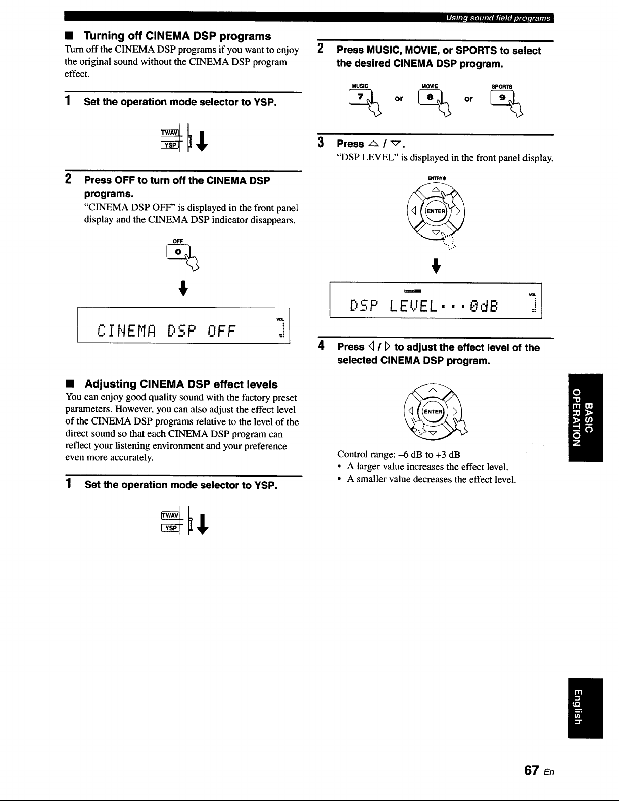
• Turning off CINEMA DSP programs
Turn off the CINEMA DSP programs if you want to enjoy
the original sound without the CINEMA DSP program
effect.
1 Set the operation mode selector to YSP.
2
l
Press OFF to turn off the CINEMA DSP
programs.
"CINEMA DSP OFF" is displayed in the front panel
display and the CINEMA DSP indicator disappears.
OFF
%
°1
CINEN_ ..n'--_,_,.NFF_ j
• Adjusting CINEMA DSP effect levels
You can enjoy good quality sound with the factory preset
parameters. However, you can also adjust the effect level
of the CINEMA DSP programs relative to the level of the
direct sound so that each CINEMA DSP program can
reflect your listening environment and your preference
even more accurately.
1 Set the operation mode selector to YSP.
2
3
I,b'III[OB-"IO1111fIilir_JI'IIhlKOI!IIP_Ilil,
Press MUSIC, MOVIE, or SPORTS to select
the desired CINEMA DSP program.
MUSIC MOVIE SPORTS
_ or _> or _
Press F,. / _.
"DSP LEVEL" is displayed in the front panel display.
ENI_YO
',.. J
%°.
I"m'-"D - '
:._,. LEUEL. • • _dB j
4 Press <1/ D to adjust the effect level of the
selected CINEMA DSP program.
Control range: -6 dB to +3 dB
• A larger value increases the effect level.
• A smaller value decreases the effect level.
67 En
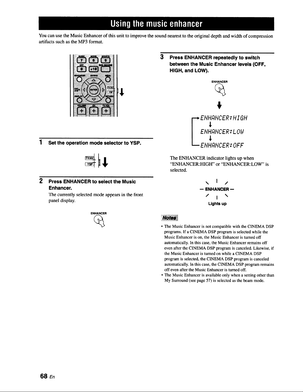
You can use the Music Enhancer of this unit to improve the sound nearest to the original depth and width of compression
artifacts such as the MP3 format.
2
Set the operation mode selector to YSP.
Press ENHANCER to select the Music
Enhancer.
The currently selectedmode appearsin the front
panel display.
ENHANCER
3
Press ENHANCER repeatedly to switch
between the Music Enhancer levels (OFF,
HIGH, and LOW).
ENHANCER
%
EHH#HCER: H I=H
ENHANCER: L Old
ENHANCER: OFF
The ENHANCER indicator lights up when
"ENHANCER:HIGH" or "ENHANCER:LOW" is
selected.
\ I /
-- ENHANCER-
/ I \
Lights up
• The Music Enhancer is not compatible with the CINEMA DSP
programs. If a CINEMA DSP program is selected while the
Music Enhancer is on, the Music Enhancer is turned off
automatically. In this case, the Music Enhancer remains off
even after the CINEMA DSP program is canceled. Likewise, if
the Music Enhancer is turned on while a CINEMA DSP
program is selected, the CINEMA DSP program is canceled
automatically. In this case, the CINEMA DSP program remains
off even after the Music Enhancer is turned off.
• The Music Enhancer is available only when a setting other than
My Surround (see page 57) is selected as the beam mode.
68 en
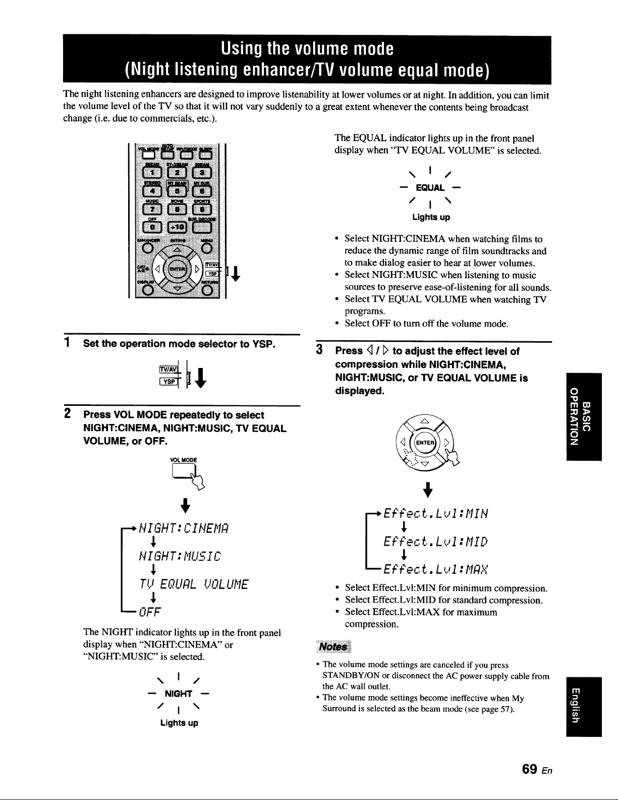
The night listening enhancers are designed to improve listenability at lower volumes or at night. In addition, you can limit
the volume level of the TV so that it will not vary suddenly to a great extent whenever the contents being broadcast
change (i.e. due to commercials, etc.).
The EQUAL indicator lights up in the front panel
display when "TV EQUAL VOLUME" is selected.
\ I /
-- EQUAL-
/ I \
Lights up
• Select NIGHT:CINEMA when watching films to
reduce the dynamic range of film soundtracks and
to make dialog easier to hear at lower volumes.
• Select NIGHT:MUSIC when listening to music
sources to preserve ease-of-listening for all sounds.
• Select TV EQUAL VOLUME when watching TV
programs.
• Select OFF to turn off the volume mode.
Set the operation mode selector to YSP.
3
Press <_I [_to adjust the effect level of
compression while NIGHT:CINEMA,
NIGHT:MUSIC, or TV EQUAL VOLUME is
displayed.
2
Press VOL MODE repeatedly to select
NIGHT:CINEMA, NIGHT:MUSIC, TV EQUAL
VOLUME, or OFF.
VOL MODE
--*HIGHT: CIHEMF4
HIGHT: MUSIC
Tt.iE_.qL/ALUOL L/ME
i OFF
The NIGHT indicator lights up in the front panel
display when "NIGHT:CINEMA" or
"NIGHT:MUSIC" is selected.
\ I /
-- NIGHT-
/ I \
Lights up
Et:'Pect.. L_..,1:MIH
". "_l._
E_p_ct..L_..,I:MID
E_ pec ...L _.,I :MF4X
Select Effect.Lvl:MIN for minimum compression.
Select Effect.Lvl:MID for standard compression.
Select Effect.Lvl:MAX for maximum
compression.
• The volume mode settings are canceled if you press
STANDBY/ON or disconnect the AC power supply cable from
the AC wall outlet.
• The volume mode settings become ineffective when My
Surround is selected as the beam mode (see page 57).
69 En
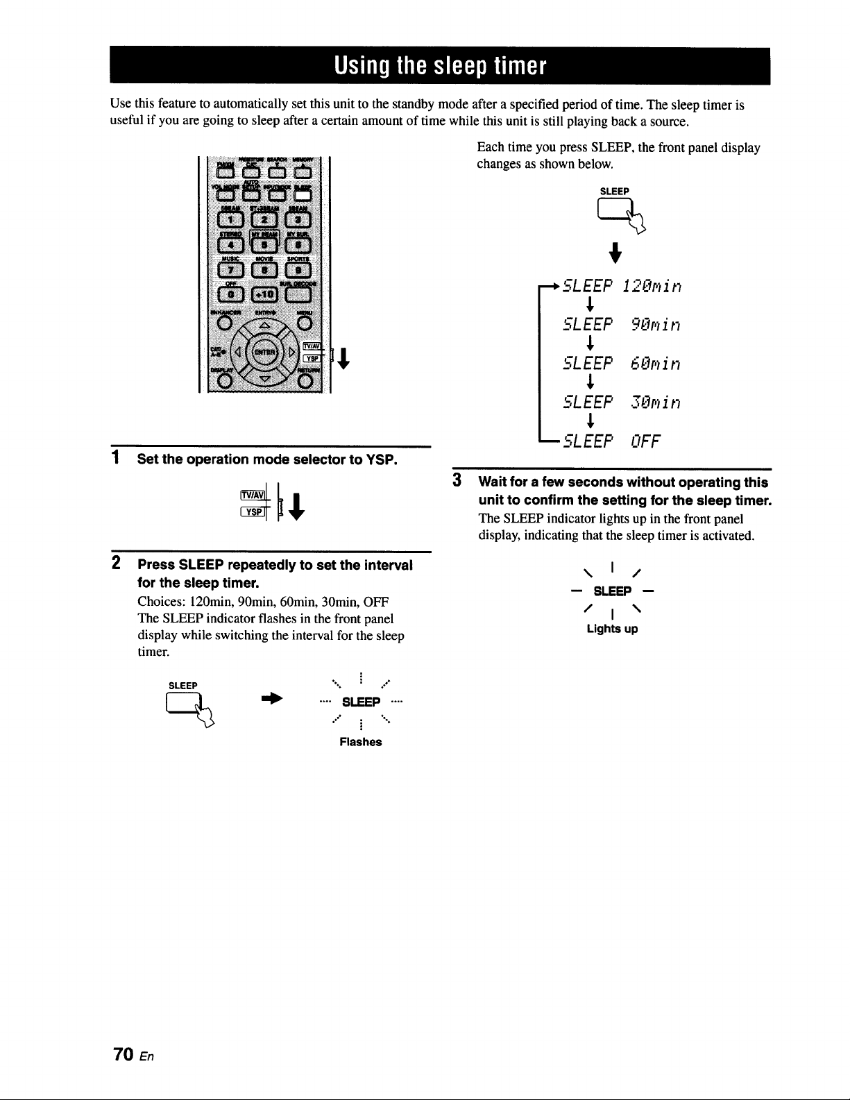
Use this feature to automatically set this unit to the standby mode after a specified period of time. The sleep timer is
useful if you are going to sleep after a certain amount of time while this unit is still playing back a source.
t
1 Set the operation mode selector to YSP.
2
Press SLEEP repeatedly to set the interval
for the sleep timer.
Choices: 120min, 90min, 60min, 30min, OFF
The SLEEP indicator flashes in the front panel
display while switching the interval for the sleep
timer.
SLEEP ". _ /
_ .... SLEEP....
Flashes
Each time you press SLEEP, the front panel display
changes as shown below.
SLEEP
•-_SLEEP 120p_in
J,
SLEEP 90p_in
,I,
'_-71_EEP 6_:'_p_in
J,
SLEEP 3_'_r,_ir,
J,
_SLEEP OFF
Wait for a few seconds without operating this
unit to confirm the setting for the sleep timer.
The SLEEP indicator lights up in the front panel
display, indicating that the sleep timer is activated.
\ I /
-- SLEEP-
/ I \
Lights up
70 En
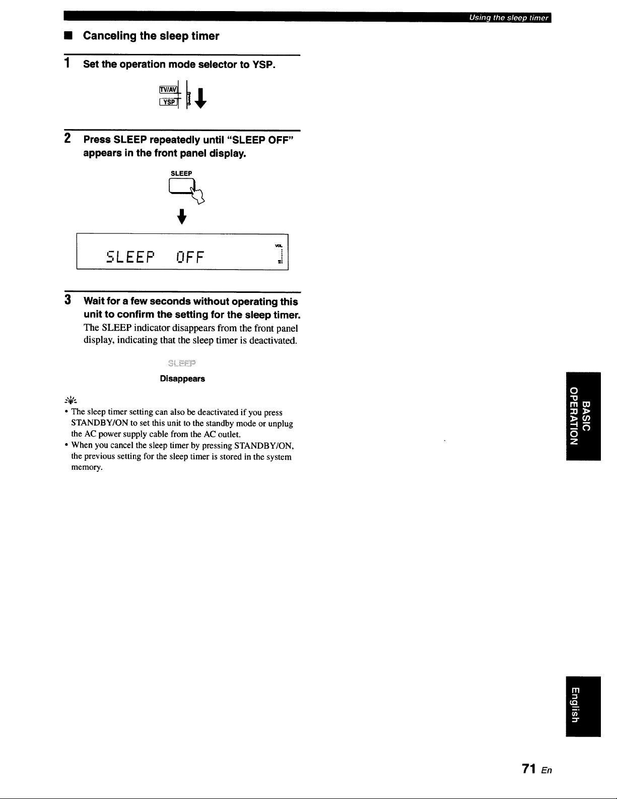
1
Canceling the sleep timer
Set the operation mode selector to YSP.
rl-'lll p mlmra-'tr_lq.a mq_l
2
Press SLEEP repeatedly until "SLEEP OFF"
appears in the front panel display.
SLEEP
va.
LEEP NFF
3
Wait for a few seconds without operating this
unit to confirm the setting for the sleep timer.
The SLEEP indicator disappears from the front panel
display, indicating that the sleep timer is deactivated.
:_:
Disappears
• The sleep timer setting can also be deactivated if you press
STANDBY/ON to set this unit to the standby mode or unplug
the AC power supply cable from the AC outlet.
• When you cancel the sleep timer by pressing STANDBY/ON,
the previous setting for the sleep timer is stored in the system
memory.
71 E,
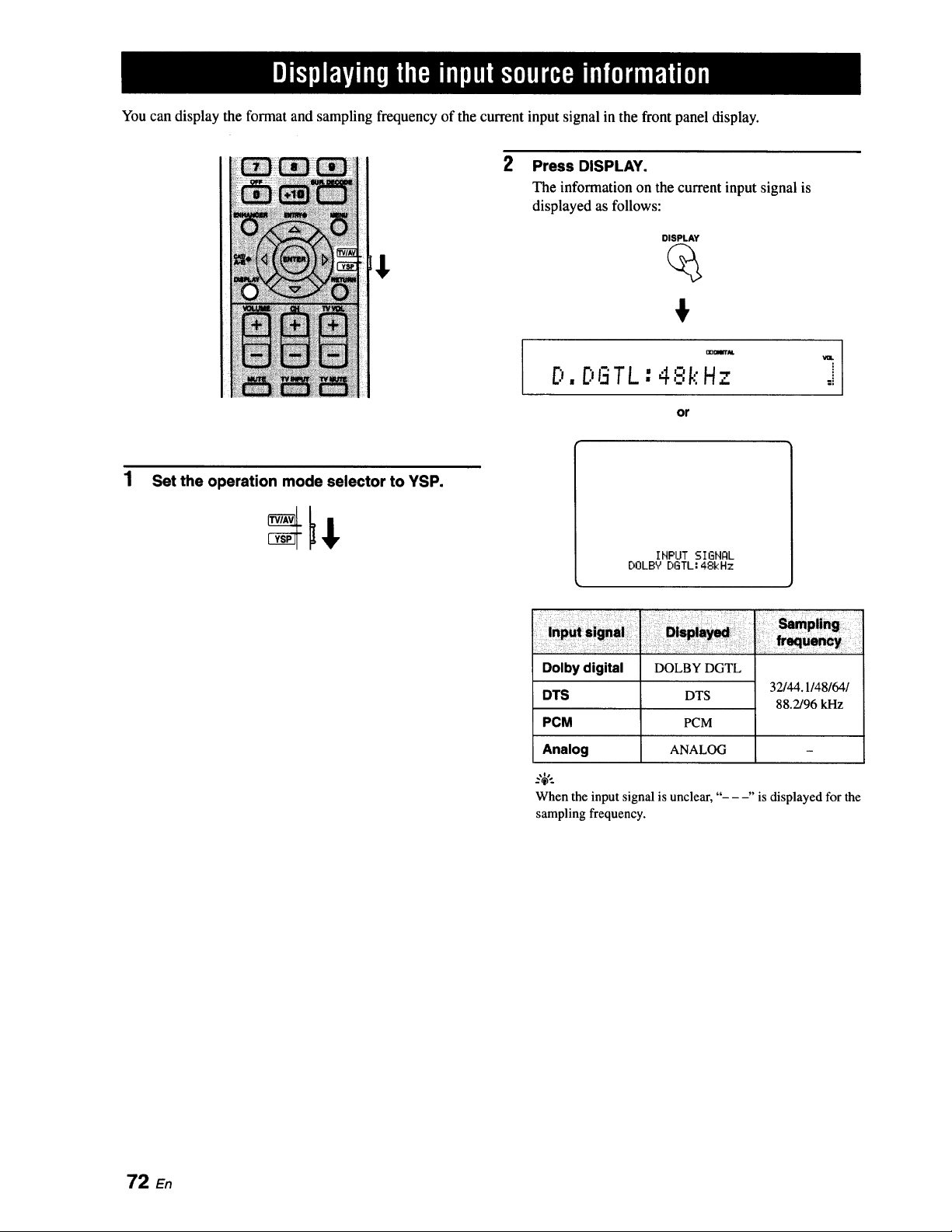
You can display the format and sampling frequency of the current input signal in the front panel display.
2
Press DISPLAY.
The information on the current input signal is
displayed as follows:
DISPLAY
€
D.DGTL:4,'.:,'kHz
or
Set the operation mode selector to YSP.
IHPUT SIGHQL
DOLBY DGTL: 48kHz
Dolby digital
DTS
PCM
Analog
DOLBY DGTL
DTS
PCM
ANALOG
32/44.1/48/64/
88.2/96 kHz
When the input signal isunclear, "- --" is displayedfor the
samplingfrequency.
72 En
You can operate the following functions using the remote control supplied with your TV if this unit and an HDMI
control-compatible TV (except some models) are connected via HDMI.
• Turning on or off the power (synchronized operation with the TV)
• Selecting the audio output component (TV or this unit)
• Adjusting the volume level (up/down and mute)
Examples of the HDMI control-compatible component are Panasonic VIERA Link compatible component (TV, DVD
recorder, Blu-ray Disc player) where VIERA Link is a new name of EZ Sync in North America and Toshiba REGZA-
LINK (its previous name is "CE Link" in North America) compatible TZs.
Not all 2008 Panasonic VIERA Link features are compatible with 2006/2007 EZ Sync products.
--'4'--
If you connect this unit to an HDMI control-compatible DVD player or Blu-ray Disc player via HDMI, you can also control the
connected component in synchronizationwith this unit (except some models).
Connect this unit to your HDMI control-compatible TV via HDMI.
For details about HDMI and HDMI components, see "Information on HDMI TM''on page 17 and "Case 1:
Connections using HDMI cables" on page 18. Also in the owner's manual supplied with your TV, refer to the
information on connecting an AV amplifier.
2 Turn on the power of all components connected via HDMI.
For details about controlling external components, see the owner's manuals supplied with your components.
3 Set HDMI control to ON. For details, refer to page 85.
4 Change the HDMI1 input at "Input assignment" to something other than "TV/STB" (for example to
"AUX1 "). (See page 82.)
5 Check the system settings for all components connected via HDMI and activate the HDMI control
feature.
For details about setting external components, see the owner's manuals supplied with your components. Once you
have followed steps 1 to 5, you do not need to carry out the same procedure again next time.
6 Turn off the power of your TV and then turn on the power again.
7 Set the input source selector of your TV to this unit (HDMI, etc.).
8
Select the connected component as the input source by pressing INPUT on the front panel of this
unit (or press one of the input selector buttons on the remote control). Confirm that the video
image played back on the DVD recorder (etc.) appears in your TV correctly.
9 Use the remote control supplied with your TV to turn on or off the power, select the audio output
component, and adjust the volume level of this unit.
• Check whether the HDMI control feature is activated for your TV (see the owner's manual supplied with your TV) if you cannot
operate this unit in synchronization with your TV.
• While you are playing back audio from a non-HDMI component, turning off the power of your TV with the remote control supplied
with your TV does not turn off the power of this unit. Playback continues without being affected.
73 En
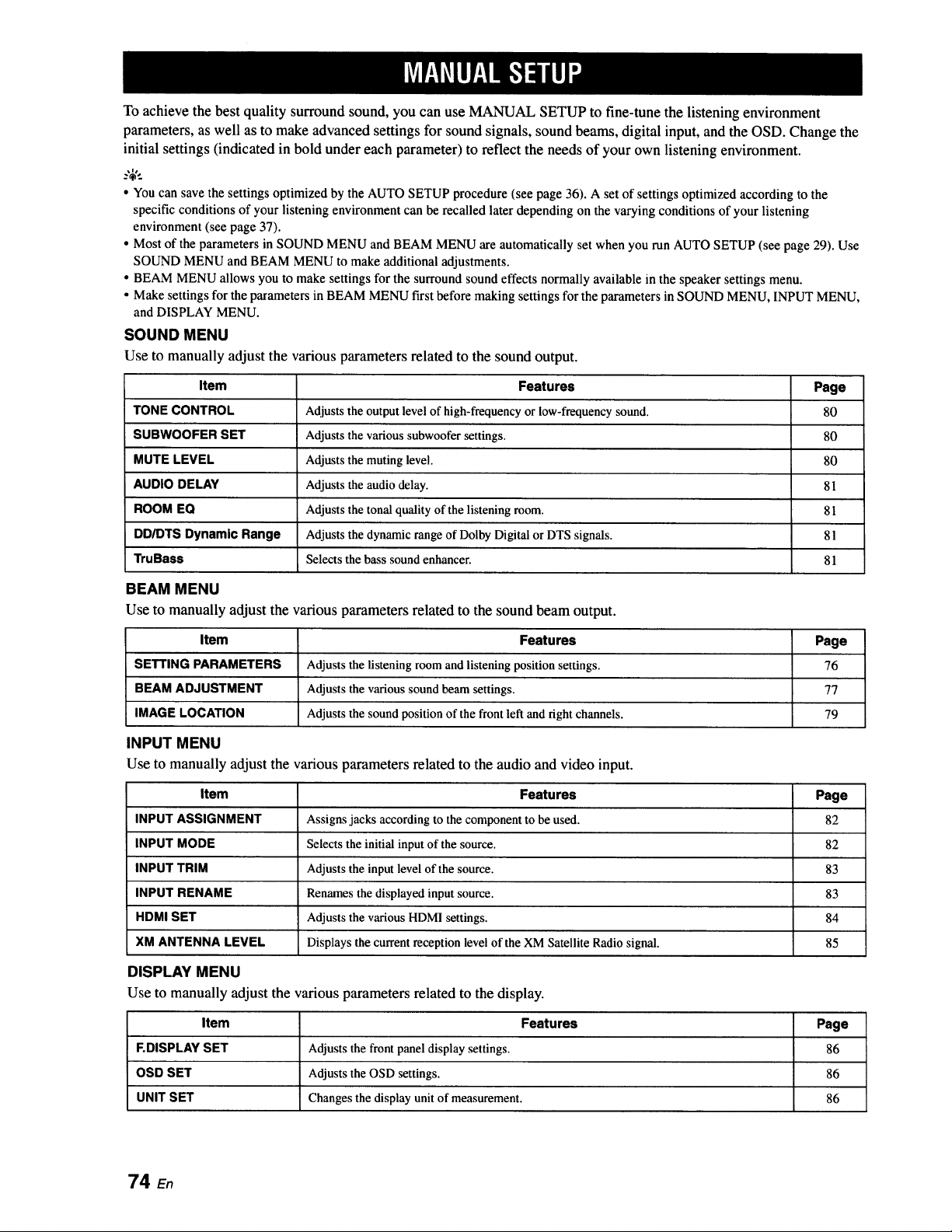
To achieve the best quality surround sound, you can use MANUAL SETUP to fine-tune the listening environment
parameters, as well as to make advanced settings for sound signals, sound beams, digital input, and the OSD. Change the
initial settings (indicated in bold under each parameter) to reflect the needs of your own listening environment.
• You can save the settings optimized by the AUTO SETUP procedure (see page 36). A set of settings optimized according to the
specific conditions of your listening environment can be recalled later depending on the varying conditions of your listening
environment (see page 37).
• Most of the parameters in SOUND MENU and BEAM MENU are automatically set when you run AUTO SETUP (see page 29). Use
SOUND MENU and BEAM MENU to make additional adjustments.
• BEAM MENU allows you to make settings for the surround sound effects normally available in the speaker settings menu.
• Make settings for the parameters in BEAM MENU first before making settings for the parameters in SOUND MENU, INPUT MENU,
and DISPLAY MENU.
SOUND MENU
Use to manually adjust the various parameters related to the sound output.
Item Features Page
TONE CONTROL Adjusts the output level of high-frequency or low-frequency sound. 80
SUBWOOFER SET Adjusts the various subwoofer settings. 80
MUTE LEVEL Adjusts the muting level. 80
AUDIO DELAY Adjusts the audio delay. 81
ROOM EQ Adjusts the tonal quality of the listening room. 81
DD/DTS Dynamic Range Adjusts the dynamic range of Dolby Digital or DTS signals. 81
TruBass Selects the bass sound enhancer. 81
BEAM MENU
Use to manually adjust the various parameters related to the sound beam output.
Item Features Page
SETTING PARAMETERS Adjusts the listening room and listening position settings. 76
BEAM ADJUSTMENT Adjusts the various sound beam settings. 77
IMAGE LOCATION Adjusts the sound position of the front left and fight channels. 79
INPUT MENU
Use to manually adjust the various parameters related to the audio and video input.
Item Features Page
INPUT ASSIGNMENT Assigns jacks according to the component to be used. 82
INPUT MODE Selects the initial input of the source. 82
INPUT TRIM Adjusts the input level of the source. 83
INPUT RENAME Renames the displayed input source. 83
HDMI SET Adjusts the various HDMI settings. 84
XM ANTENNA LEVEL Displays the current reception level of the XM Satellite Radio signal. 85
DISPLAY MENU
Use to manually adjust the various parameters related to the display.
Item Features Page
F.DISPLAY SET Adjusts the front panel display settings. 86
OSD SET Adjusts the OSD settings. 86
UNIT SET Changes the display unit of measurement. 86
74
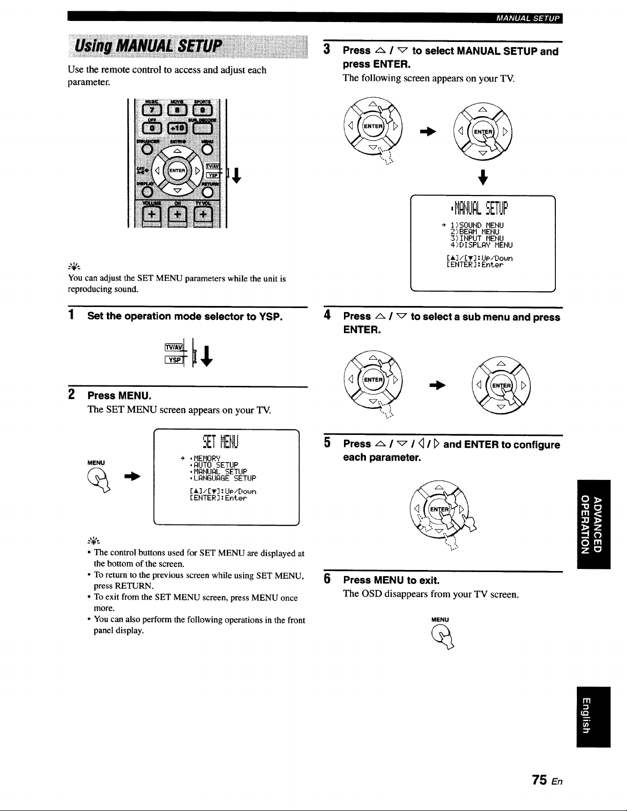
Use the remote control to access and adjust each
parameter.
Youcan adjust the SET MENU parameters while the unit is
reproducing sound.
1 Set the operation mode selector to YSP.
2 Press MENU.
The SET MENU screen appears on your TV.
3 Press _ / _ to select MANUAL SETUP and
press ENTER.
The following screen appears on your TV.
,HFIHUI LSETUP
÷ I)SOUND MENU
2)BEAH MENU
3)INPUT MENU
4)DISPLAY MENU
[A]/[_]:UP/Down
[ENTER]:EnteP
4
PressAl_toselectasub menuandpress
ENTER.
MENU
.MEMORY
•AUTO SETUP
•MANUAL SETUP
•LANGUAGE SETUP
[A]i[_]:UP/Do_n
[ENTER]:EnteP
• The control buttons used for SET MENU aredisplayed at
the bottom of the screen.
• To return to the previous screen while using SET MENU,
press RETURN.
• To exit from the SET MENU screen, press MENU once
more.
• Youcan also perform the followingoperations in the front
panel display.
Press A i _ I <_I [_ and ENTER to configure
each parameter.
,'...,'.
,o..
6 Press MENU to exit.
The OSD disappears from your TV screen.
MENU
75 En
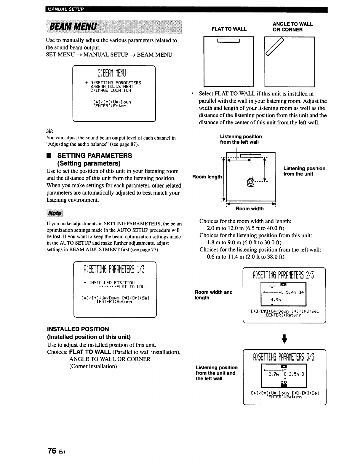
m'_ra,,'Ff:R[-7:llIJ"
Use to manually adjust the various parameters related to
the sound beam output.
SET MENU _ MANUAL SETUP _ BEAM MENU
,'_ _ "_
:,,BEHMMENU
÷ A_',SETTIHG PARAr,IETERS
B>BEAM AD.IUSTHENT
C) INAGE LOCATION
[_3/[_'] :Up/Dot,Jn
[ENTER ]:Enter
Youcan adjust the sound beam output level of each channel in
"Adjustingthe audio balance" (see page 87).
• SETTING PARAMETERS
(Setting parameters)
Use to set the position of this unit in your listening room
and the distance of this unit from the listening position.
When you make settings for each parameter, other related
parameters are automatically adjusted to best match your
listening environment.
If you make adjustments in SETTING PARAMETERS, the beam
optimization settings made in the AUTO SETUP procedure will
be lost. If you want to keep the beam optimization settings made
in the AUTO SETUP and make further adjustments, adjust
settings in BEAM ADJUSTMENT first (see page 77).
A'r "
,,-,ETTIH{ PARAMETERSi,'3
÷ INSTALLED POSITION
....... FLAT TO WALL
[,I, 3/[_] :UP/DOtJFI [-,i]/[l,-] :Sel
[ ENTER ] :Return
INSTALLED POSITION
(Installed position of this unit)
Use to adjust the installed position of this unit.
Choices: FLAT TO WALL (Parallel to wall installation),
ANGLE TO WALL OR CORNER
(Comer installation)
ANGLE TO WALL
OR CORNER
Select FLAT TO WALL if this unit is installed in
parallel with the wall in your listening room. Adjust the
width and length of your listening room as well as the
distance of the listening position from this unit and the
distance of the center of this unit from the left wall.
Listening position
from the left wall
Room,eng,!I
,4 =9
Room width
-- Listening position
from the unit
Choices for the room width and length:
2.0 m to 12.0 m (6.5 ft to 40.0 ft)
Choices for the listening position from this unit:
1.8 m to 9.0 m (6.0 ft to 30.0 ft)
Choices for the listening position from the left wall:
0.6 m to 11.4 m (2.0 ft to 38.0 ft)
Room width and
length
_l,,ic r; i- -, r '7,,,_
o.,ETTIttl=FHRHI'IETER-,
I I
÷--+---[ 5.4m 3->
I
4,9n
J,
[i]/[T] :UP/Dob.m E-W3/EW-3:Sel
[ENTER ] :Return
Listening position
from the unit and
the left wall
€
N,,:,ETTIN 5F'RRRMETERS':',,,,:,
° 1
÷ ...... -).?
2,7m E 2,5m ]
4,
E_],"[_F]: UP/Dot,Jn [-,I],.'[lm-] :501
[ENTER ] : Re_urh
76 En
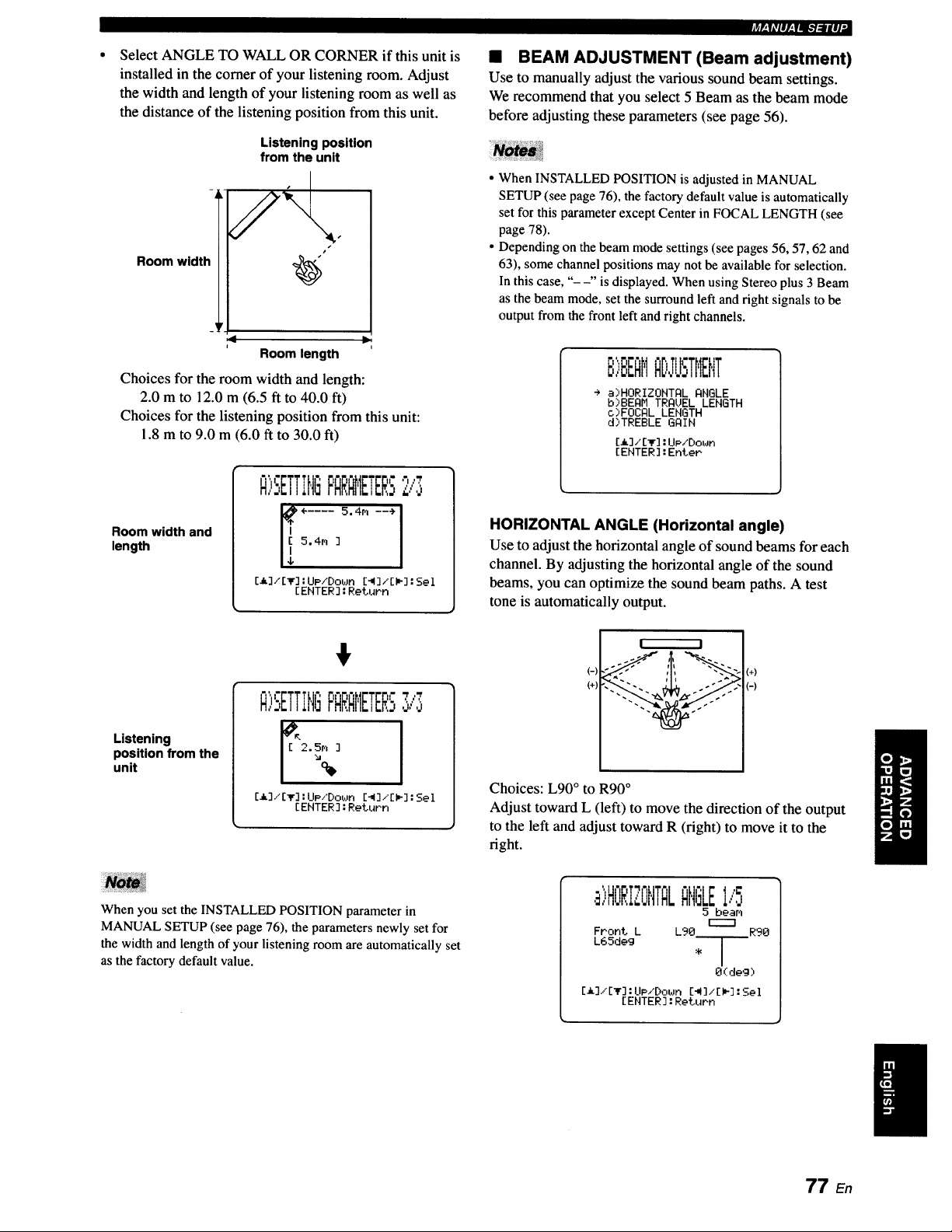
Select ANGLE TO WALL OR CORNER if this unit is
installed in the comer of your listening room. Adjust
the width and length of your listening room as well as
the distance of the listening position from this unit.
Room width
Listening position
from the unlt
s
:< It.
Room length
Choices for the room width and length:
2.0 m to 12.0 m (6.5 ft to 40.0 ft)
Choices for the listening position from this unit:
1.8 m to 9.0 m (6.0 ft to 30.0 ft)
Room width and
length
";I" 't ",
F'QRQt,IETERS2/3
E_],'I_] :UP/Dot,Jn [_3,°[_3 :Sel
[ENTER] :Return
_p.|iVlll,.|l_lgl|li,
• BEAM ADJUSTMENT (Beam adjustment)
Use to manually adjust the various sound beam settings.
We recommend that you select 5 Beam as the beam mode
before adjusting these parameters (see page 56).
• When INSTALLED POSITION is adjusted in MANUAL
SETUP (see page 76), the factory default value is automatically
set for this parameter except Center in FOCAL LENGTH (see
page 78).
• Depending on the beam mode settings (see pages 56, 57, 62 and
63), some channel positions may not be available for selection.
In this case, "- -" is displayed. When using Stereo plus 3 Beam
as the beam mode, set the surround left and right signals to be
output from the front left and right channels.
I'; I "I
B,,,,E,EFIIIIiD,TUSTHENT
÷ a)HORIZONTAL ANGLE
b)BEAH TRAUEL LENGTH
c)FOCAL LENGTH
d)TREBLE GAIN
[_],'[_] : UP,'Doz_Jn
[ENTER] : Enter
HORIZONTAL ANGLE (Horizontal angle)
Use to adjust the horizontal angle of sound beamsfor each
channel. By adjusting the horizontal angle of the sound
beams, you can optimize the sound beam paths. A test
tone is automatically output.
Listening
position from the
unit
$
i= T ,'=', r ,rT.T
A;SETT,t,IGFNRNE ERz,,,,
E_]/[Ir] :Upi'Dot,Jn[_3,"[_] :Sol
[ENTER] :Return
(-)
(+)
! I
(+)
(-)
Choices: L90 ° to R90 °
Adjust toward L (left) to move the direction of the output
to the left and adjust toward R (right) to move it to the
fight.
When you set the INSTALLED POSITION parameter in
MANUAL SETUP (see page 76), the parameters newly set for
the width and length of your listening room are automatically set
as the factory default value.
,B)HORIZONTQLANGLEI/5
5 beam
r----7
Front L L90 R90
L65deg
O(deg)
[_]/[_] :UP/Down [_]/[)_] :Sel
[ENTER] : Return
I
77 En
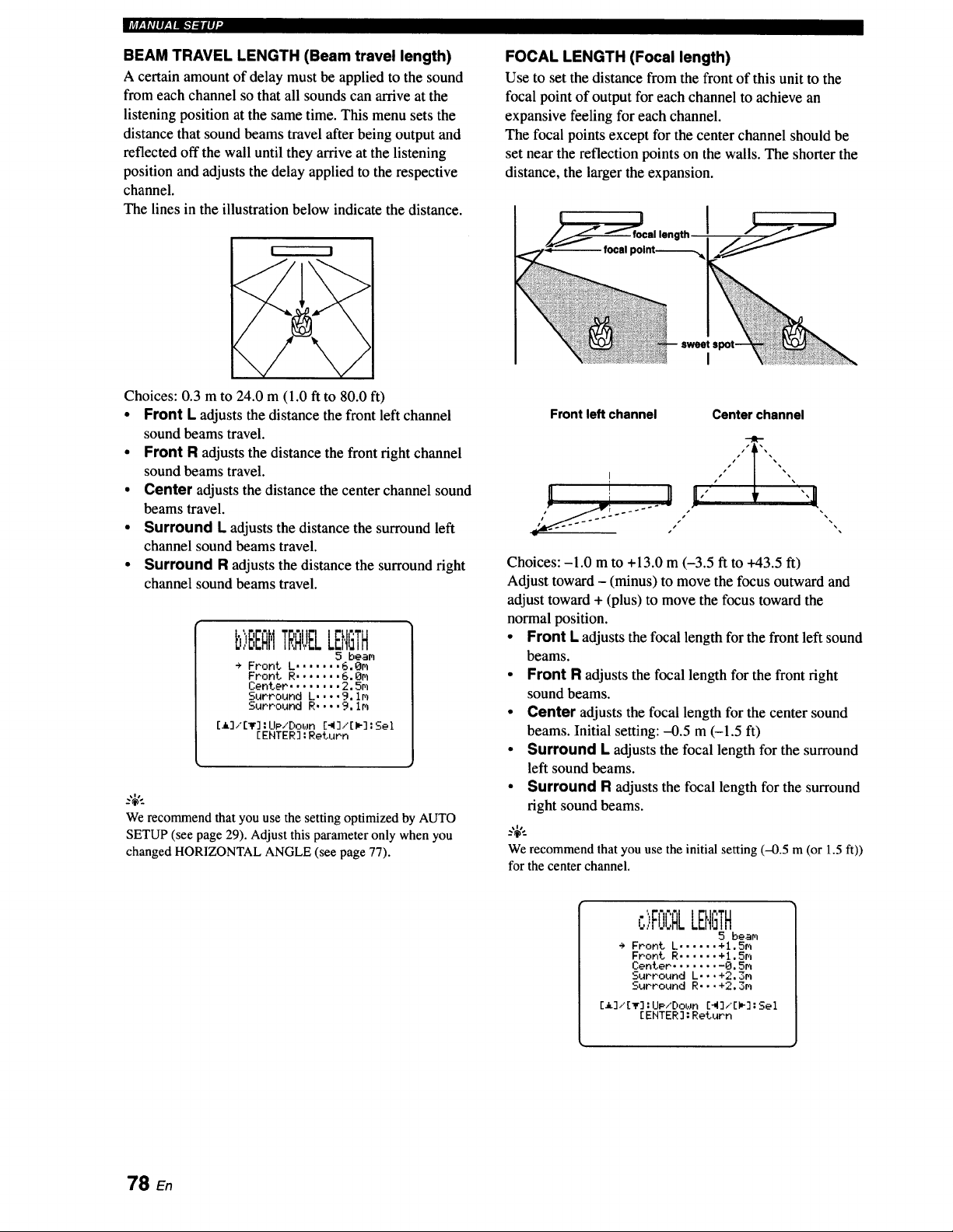
ImV_,v,,llv_.v_-1.-Iiq-
BEAM TRAVEL LENGTH (Beam travel length)
A certain amount of delay must be applied to the sound
from each channel so that all sounds can arrive at the
listening position at the same time. This menu sets the
distance that sound beams travel after being output and
reflected off the wall until they arrive at the listening
position and adjusts the delay applied to the respective
channel.
The lines in the illustration below indicate the distance.
I t I
Choices: 0.3 m to 24.0 m (1.0 ft to 80.0 ft)
• Front L adjusts the distance the front left channel
sound beams travel.
• Front R adjusts the distance the front right channel
sound beams travel.
• Center adjusts the distance the center channel sound
beams travel.
• Surround L adjusts the distance the surround left
channel sound beams travel.
• Surround R adjusts the distance the surround right
channel sound beams travel.
b)EEQMTRAUELLENGTH
5 beam
->Front.L .......6.Om
Front R ....... 6. Om
Center ........ 2.5m
Surround L .... 9, Im
Surround R .... 9. im
[_]/[T] : UP/Doun [_]/[i_] : Sel
[ENTER] : Return
We recommend that you use the setting optimizedby AUTO
SETUP (see page 29). Adjustthis parameteronly when you
changed HORIZONTALANGLE (see page 77).
FOCAL LENGTH (Focal length)
Use to set the distance from the front of this unit to the
focal point of output for each channel to achieve an
expansive feeling for each channel.
The focal points except for the center channel should be
set near the reflection points on the walls. The shorter the
distance, the larger the expansion.
I
Front left channel
Center channel
Choices: -1.0 m to +13.0 m (-3.5 ft to +43.5 ft)
Adjust toward - (minus) to move the focus outward and
adjust toward + (plus) to move the focus toward the
normal position.
• Front L adjusts the focal length for the front left sound
beams.
• Front R adjusts the focal length for the front right
sound beams.
• Center adjusts the focal length for the center sound
beams. Initial setting: -0.5 m (-1.5 ft)
• Surround L adjusts the focal length for the surround
left sound beams.
• Surround R adjusts the focal length for the surround
right sound beams.
We recommendthat you use the initial setting (-0.5 m(or 1.5 ft))
for the center channel.
c>FOC&LENGTH
5 beam
÷ Front L ...... +l.Sm
Front R ...... +l,Sm
Center ........ 0,5m
Surround L.,.+2,3m
Surround R...+2.3m
[i]/[_]:Ue.xDoun [4],"[*]:Sel
[ENTER]:Return
78 En
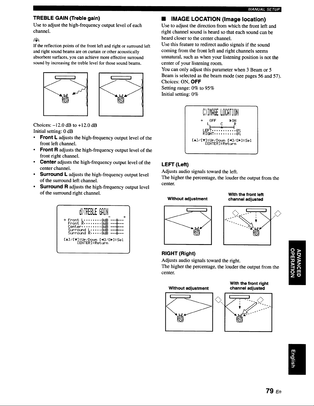
TREBLE GAIN (Treble gain)
Use to adjust the high-frequency output level of each
channel.
_%',_
If the reflection points of the front left and right or surround left
andright sound beams are on curtain or other acoustically
absorbent surfaces,you can achieve more effective surround
sound by increasing the treble level for those sound beams.
! I ! I
Choices: -12.0 dB to +12.0 dB
Initial setting: 0 dB
• Front L adjusts the high-frequency output level of the
front left channel.
• Front R adjusts the high-frequency output level of the
front fight channel.
• Center adjusts the high-frequency output level of the
center channel.
• Surround L adjusts the high-frequency output level
of the surround left channel.
• Surround R adjusts the high-frequency output level
of the surround fight channel.
d)TREBLEGAiN
+
÷ Front L ........ OdB --4k--
Front R ........ OdB --4k--
Center ......... OdB --4N--
Surround L ..... OdB --4k--
Surround R ..... OdB --qF--
[_]/[_]:UP/Doun [_]/[P]:Sel
[EHTER]:RetuPn
IrAF.,Y@II[,.|Idl,P]_Igll ,
[] IMAGE LOCATION (Image location)
Use to adjust the direction from which the front left and
fight channel sound is heard so that each sound can be
heard closer to the center channel.
Use this feature to redirect audio signals if the sound
coming from the front left and fight channels seems
unnatural, such as when your listening position is not the
center of your listening room.
You can only adjust this parameter when 3 Beam or 5
Beam is selected as the beam mode (see pages 56 and 57).
Choices: ON, OFF
Setting range: 0% to 95%
Initial setting: 0%
C';,IMAGELOCATIOH
÷ OFF )'OH
LEF_ ........... 0%
RIGHT ..........0_;
Ca]/[_] :UP/Doun [41]/[I_]:Sel
[ENTER]: Return
LEFT (Left)
Adjusts audio signals toward the left.
The higher the percentage, the louder the output from the
center.
Without adjustment
With the front left
channel adjusted
RIGHT (Right)
Adjusts audio signals toward the right.
The higher the percentage, the louder the output from the
center.
Without adjustment
With the front right
channel adjusted
79 En

l,_r-mu.a_.l_lri-
Use to manually adjust the various parameters related to
the sound output.
SET MENU -_ MANUAL SETUP --, SOUND MENU
I>SOUNDMEt,IV
÷ A)TOHE CONTROL
B>SUBWOOFER SET
C>HUTE LEVEL
D>AUDIO DELAY
E>ROOH EQ
F>DD/DTS D_naMic Range
G>TruBass
[_]/[T]:UP/Down
EEHTER]:Enter
• TONE CONTROL (Tone control)
You can adjust the tonal quality of sound beams.
R)TONECONTROL
- +
TREBLE ..... OdB ---IF--
- +
BASS ....... OdB ---IF--
[A]/[_]:UP/Dob_n [_]/[W]:Sel
[ENTER]:Return
TREBLE (Treble)
Use to adjust the high-frequency response.
Choices: -12 dB to +12 dB
Initial setting: 0 dB
BASS (Bass)
Use to adjust the low-frequency response.
Choices: -12 dB to ÷12 dB
Initial setting: 0 dB
• SUBWOOFER SET (Subwoofer settings)
Use to manually adjust the various subwoofer
settings.
BASS OUT (Bass out)
Low-frequency (bass) signals can be directed to the
subwoofer or the front left and right channels. This setting
also determines the routing of LFE (low-frequency effect)
signals found in Dolby Digital or DTS sources.
Choices: SUBWOOFER (Subwoofer), FRONT
• Select SUBWOOFER if you connect a subwoofer. LFE
and low-frequency signals from other channels are
directed to the subwoofer.
• Select FRONT if you do not use a subwoofer. LFE and
low-frequency signals from other channels are directed
to the front left and right channels.
CROSS OVER (Crossover)
When BASS OUT is set to SUBWOOFER, you can use
this feature to select a crossover (cutoff) frequency for all
low-frequency signals. All frequencies below the selected
frequency will be sent to the subwoofer position.
Choices: 80Hz, 100Hz, 120Hz
LFE LEVEL (Low-frequency effect level)
Select to adjust the output level of the LFE (low-frequency
effect) channel according to the capacity of your
subwoofer. The LFE channel carries low-frequency
special effects which are only added to certain scenes.
This setting is effective only when this unit decodes Dolby
Digital or DTS signals.
Choices: -20 to 0 dB
DISTANCE (Distance)
Select to adjust the distance of the subwoofer from the
listening position.
Choices: 0.3 to 15.0 m (1.0 ft to 50.0 ft)
Initial setting: 3.0 m (10.0 ft)
• MUTE LEVEL (Muting level)
Use to adjust how much the mute function reduces the
volume level.
Choices: MUTE, -20 dB
° Select MUTE to completely halt all sound output.
• Select -20 dB to reduce the current volume level by
20 dB.
_.,IM -.
B,:,JE,JuuFERSET
* BRSS OUT ..... FRONT
CROSS OVER,.,IOOHz
LFE LEVEL ...... OdB
DISTRNCE ...... 3.0m
[_]/[T]:UP,"Down [_]/[m]:Sel
[ENTER]:RetuPn
C>MUTELEE
_MUTE -20dB
[_]/[_]:Select
[ENTER]:Return
80 En

• AUDIO DELAY (Audio delay)
Use to delay the sound output and synchronize it with the
video image. This may be necessary when using certain
LCD monitors or projectors.
Choices: 0 to 160 msec
D)QU[:,IODELAY
AUDIO DELAY ..... Or_sec
[_]/[_] :Select
[ENTER ]:Return
• ROOM EQ (Room equalizer)
Use to change the tonal qualities of your listening room
when the unit is mounted on the wall.
Choices: MOUNTING (Mount type),
REFLECTING (Reflectivity type)
E,)ROOMEQ
÷ HOUNTIHG ..... SHELF
REFLECT IFIG.••HORHAL
[A]/[_r] :UP/Do_Jn [41]/[I_]:Sel
[EHTER ]: Return
MOUNTING (Mounting type)
Use to enhance medium to low range sounds.
Choices: WALL (Wall mount), SHELF (Shelf mount)
• Select WALL if this unit is mounted on the wall in your
listening room.
• Select SHELF if this unit is mounted on the shelf in
your listening room.
REFLECTING (Reflectivity type)
Use to select the reflectivity of your listening room.
Choices: NORMAL (Normal), HI ECHO (High echo)
• Select NORMAL if your listening room has a normal
reflectivity.
• Select HI ECHO if your listening room has highly
reflective surfaces such as concrete walls.
:_p. IAvlIp.l IB."l,_ltlll .
• DD/DTS Dynamic Range
(Dynamic range of Dolby Digital and
DTS signals)
Use to select the amount of dynamic range compression.
This setting is effective only when the unit is decoding
Dolby Digital and DTS signals. Dynamic range is the
difference between the smallest sound that can be heard
above the noise of the equipment and the biggest sound
that can be heard without distortion.
Choices: MIN (minimum), STD (standard),
MAX (maximum)
I= "1 •
F)DD,'DTS[:,'.4nat,lieR. ng.
MIH STD I_HQX
C_]/[_] :Select
[EHTER] :Return
Select to adjust the dynamic range compression.
• Select MIN for listening to sources at low volume
levels.
• Select STD for general use.
• Select MAX for feature films.
• TruBass
Use to turn on or off the bass sound enhancer. The SRS
TruBass technology improves bass even without a
subwoofer and provides deeper, richer bass in the presence
of a subwoofer.
Choices: OFF, ON
OFF _OH
[_]/[I_] :Select
[EHTER ] :Return
TruBass is not available when My Beam (see page 63) or My
Surround (see page 57) is selected as the beam mode.
81 En
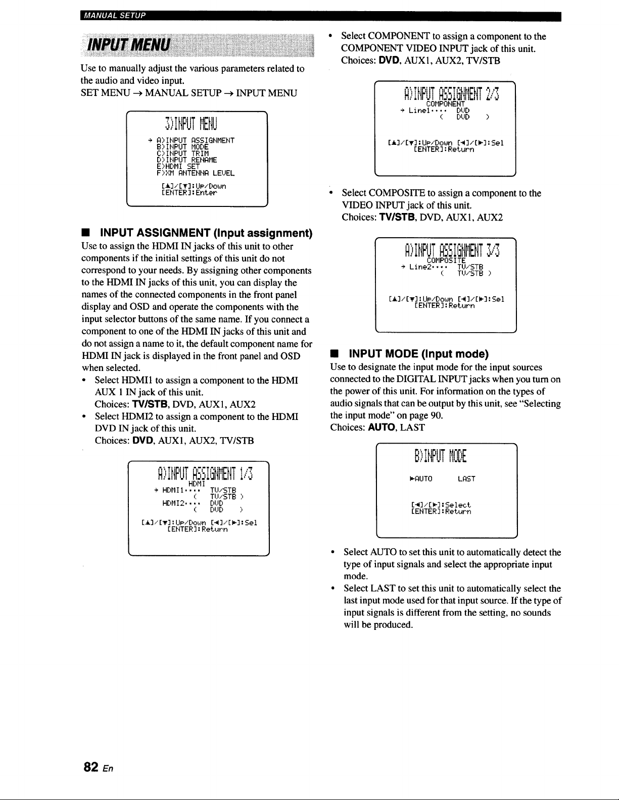
l,'_r;v,'|_,_Tqq_lq"
Use to manually adjust the various parameters related to
the audio and video input.
SET MENU -_ MANUAL SETUP --_ INPUT MENU
" 'l
,IHFJTMEHU
+ Q)INPUT ASSIGNMENT
B)INPUT MODE
C)INPUT TRIM
D)INPUT RENAME
E)HDMI SET
F)XM ANTENNA LEUEL
[_k]/ [_F]:UP/Down
[ENTER ]:Enter
• INPUT ASSIGNMENT (Input assignment)
Use to assign the HDMI IN jacks of this unit to other
components if the initial settings of this unit do not
correspond to your needs. By assigning other components
to the HDMI IN jacks of this unit, you can display the
names of the connected components in the front panel
display and OSD and operate the components with the
input selector buttons of the same name. If you connect a
component to one of the HDMI IN jacks of this unit and
do not assign a name to it, the default component name for
HDMI IN jack is displayed in the front panel and OSD
when selected.
• Select HDMI1 to assign a component to the HDMI
AUX 1 IN jack of this unit.
Choices: TV/STB, DVD, AUX1, AUX2
• Select HDMI2 to assign a component to the HDMI
DVD IN jack of this unit.
Choices: DVD, AUX1, AUX2, TV/STB
R"ITtigttT "lr,'Th , ! ,:7
u F,J[,i_F,JT
, mrJl 1"_,
HDMI
÷ HDMI1.... TU/STB
( TU/STB)
HDMI2.... DUD
( DUD )
[_.]i[V] : UP/Down [-,I]/'[I,-] : Sel
[ ENTER ] : Return
Select COMPONENT to assign a component to the
COMPONENT VIDEO INPUT jack of this unit.
Choices: DVD, AUX1, AUX2, TV/STB
"rr ",i ,'i,'7
R)IHF'UTb. II.i['IIlEt'IT,:,'o
COMPONENT
÷ Linel .... DUD
( DUD )
[.,I,.]./[v] :UP/Down [_]/[P] :Sel
[ENTER ]:Return
Select COMPOSITE to assign a component to the
VIDEO INPUT jack of this unit.
Choices: TVISTB, DVD, AUX1, AUX2
R:,INPUTQSSIGNt'IENT
COMPOS ITE
÷ Line2 .... TU/STB
( TU/STB ;,
[a]/[v] :UP/Down C4]/[I_] :Sel
[ENTER ]:Return
• INPUT MODE (Input mode)
Use to designate the input mode for the input sources
connected to the DIGITAL INPUT jacks when you turn on
the power of this unit. For information on the types of
audio signals that can be output by this unit, see "Selecting
the input mode" on page 90.
Choices: AUTO, LAST
B)IHPUTMODE
PQUTO LAST
[_]./[_]:Select
[ENTER]:Return
Select AUTO to set this unit to automatically detect the
type of input signals and select the appropriate input
mode.
Select LAST to set this unit to automatically select the
last input mode used for that input source. If the type of
input signals is different from the setting, no sounds
will be produced.
82
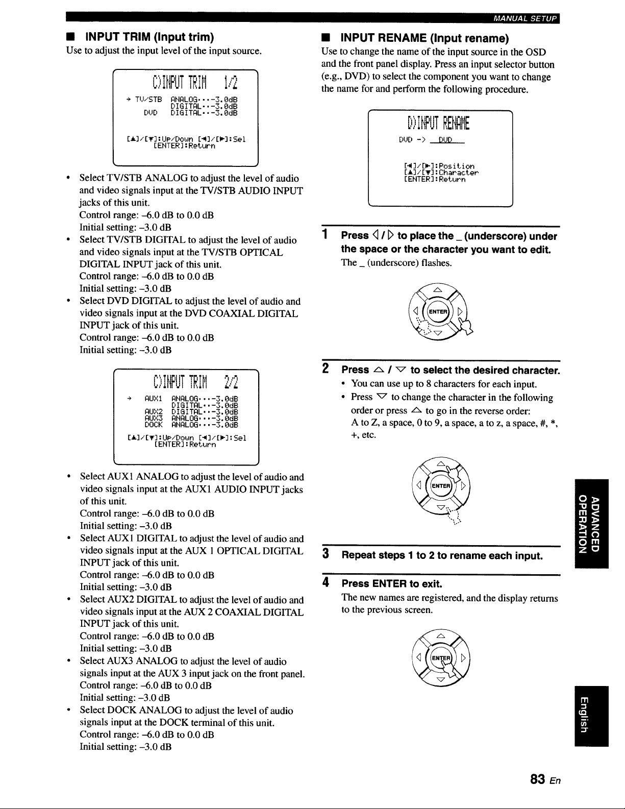
• INPUT TRIM (Input trim)
Use to adjust the input level of the input source.
C:,:,INPUTTRiMI,'2
+ TU/STB ANALOG .... 3.0dB
DI G I TAL., -3. OdB
DUD DIGITAL..-3, OdB
[h.]/[_']"UP/Dot_n [41]/[I_]:Sel
[ENTER] :Return
• Select TV/STB ANALOG to adjust the level of audio
and video signals input at the TV/STB AUDIO INPUT
jacks of this unit.
Control range: -6.0 dB to 0.0 dB
Initial setting: -3.0 dB
• Select TV/STB DIGITAL to adjust the level of audio
and video signals input at the TV/STB OPTICAL
DIGITAL INPUT jack of this unit.
Control range: -6.0 dB to 0.0 dB
Initial setting: -3.0 dB
• Select DVD DIGITAL to adjust the level of audio and
video signals input at the DVD COAXIAL DIGITAL
INPUT jack of this unit.
Control range: -6.0 dB to 0.0 dB
Initial setting: -3.0 dB
C>IHPUTTRIM2/2
AUXI ANALOG .... 3. OdB
DIGITAL..-3.QdB
AUX2 DIGITAL..-3.0dB
AUX3 ANALOG .... 3,OdB
DOCK ANALOG .... 3.0dB
[i]/[_r] :UP/Down [_],'[I_]:Sel
[ENTER] :Return
• Select AUX1 ANALOG to adjust the level of audio and
video signals input at the AUX1 AUDIO INPUT jacks
of this unit.
Control range: -6.0 dB to 0.0 dB
Initial setting: -3.0 dB
• Select AUX 1 DIGITAL to adjust the level of audio and
video signals input at the AUX 1 OPTICAL DIGITAL
INPUT jack of this unit.
Control range: -6.0 dB to 0.0 dB
Initial setting: -3.0 dB
• Select AUX2 DIGITAL to adjust the level of audio and
video signals input at the AUX 2 COAXIAL DIGITAL
INPUT jack of this unit.
Control range: -6.0 dB to 0.0 dB
Initial setting: -3.0 dB
• Select AUX3 ANALOG to adjust the level of audio
signals input at the AUX 3 input jack on the front panel.
Control range: -6.0 dB to 0.0 dB
Initial setting: -3.0 dB
• Select DOCK ANALOG to adjust the level of audio
signals input at the DOCK terminal of this unit.
Control range: -6.0 dB to 0.0 dB
Initial setting: -3.0 dB
_F:;#IIPfq_'/:ll#]"
• INPUT RENAME (Input rename)
Use to change the name of the input source in the OSD
and the front panel display. Press an input selector button
(e.g., DVD) to select the component you want to change
the name for and perform the following procedure.
[:,)INPUTREHQME
DUD -> DUD
[_ ]/EL] :Position
EL] / [T] :Character
[ENTER] :Return
Press <_I l> to place the _ (underscore) under
the space or the character you want to edit.
The _ (underscore) flashes.
2
Press _, / _ to select the desired character.
• You can use up to 8 characters for each input.
• Press _ to change the character in the following
order or press Lx to go in the reverse order:
A to Z, a space, 0 to 9, a space, a to z, a space, #, *,
+, etc.
3 Repeat steps I to 2 to rename each input.
4 Press ENTER to exit.
The new names are registered, and the display returns
to the previous screen.
83 En
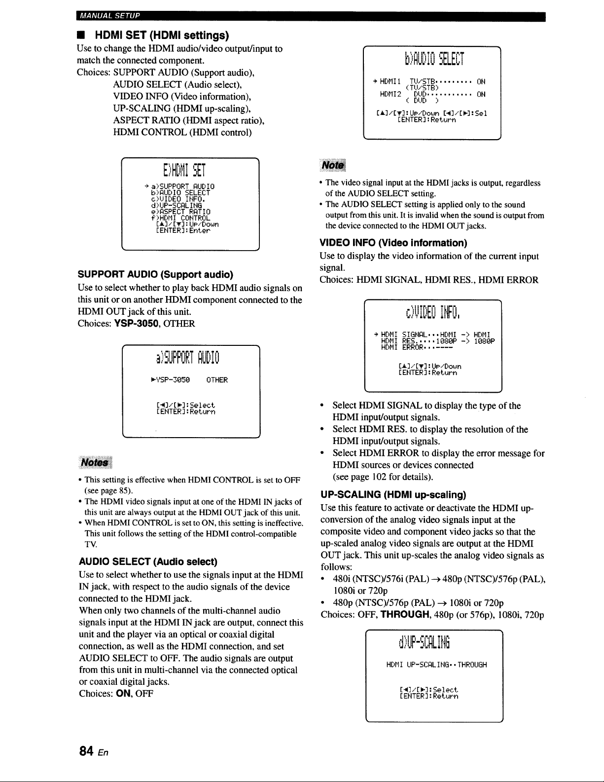
mmmr,_Pli-7:UlV
• HDMI SET (HDMI settings)
Use to change the HDMI audio/video output/input to
match the connected component.
Choices: SUPPORT AUDIO (Support audio),
AUDIO SELECT (Audio select),
VIDEO INFO (Video information),
UP-SCALING (HDMI up-scaling),
ASPECT RATIO (HDMI aspect ratio),
HDMI CONTROL (HDMI control)
i,m -,
b)RUDIO-,ELB;T
+ HDMII TU/STB ......... ON
(TU/STB)
HDMI2 DUD ........... ON
( DUD )
[_]/[_]:IJp/Do_m [_]/[_]:Sel
[ENTER]:Return
E)HDMISET
+ a)SUPPORT QUDIO
b)QUDIO SELECT
c)UIDEO INFO.
d)UP-SCQLING
e)QSPECT RQTIO
g)HOHl CONTROL
[_]/[_]:UpiDown
[ENTER]:Enter
SUPPORT AUDIO (Support audio)
Use to select whether to play back HDMI audio signals on
this unit or on another HDMI component connected to the
HDMI OUT jack of this unit.
Choices: YSP-3050, OTHER
,_"11" I I" I
,:,UFFURTI:IUDIO
I,-YSP-3050 OTHER
[_]/[i_] : Select
[ ENTER ] : Return
• This setting is effective when HDMI CONTROL is set to OFF
(see page 85).
• The HDMI video signals input at one of the HDMI IN jacks of
this unit are always output at the HDM1 OUT jack of this unit.
• When HDMI CONTROL is set to ON, this setting is ineffective.
This unit follows the setting of the HDMI control-compatible
TV.
AUDIO SELECT (Audio select)
Use to select whether to use the signals input at the HDMI
IN jack, with respect to the audio signals of the device
connected to the HDMI jack.
When only two channels of the multi-channel audio
signals input at the HDMI IN jack are output, connect this
unit and the player via an optical or coaxial digital
connection, as well as the HDMI connection, and set
AUDIO SELECT to OFF. The audio signals are output
from this unit in multi-channel via the connected optical
or coaxial digital jacks.
Choices: ON, OFF
• The video signal input at the HDMI jacks is output, regardless
of the AUDIO SELECT setting.
• The AUDIO SELECT setting is applied only to the sound
output from this unit. It is invalid when the sound is output from
the device connected to the HDMI OUT jacks.
VIDEO INFO (Video information)
Use to display the video information of the current input
signal.
Choices: HDMI SIGNAL, HDMI RES., HDMI ERROR
,:,)UIDEOII,IFO,
÷ HDMI SIGNAL...HDMI -> HDHI
HDMI RES.....1080P-> 1080P
HDMI ERROR.......
[_]/[T] :UP/Down
[EHTER ] :Return
• Select HDMI SIGNAL to display the type of the
HDMI input/output signals.
• Select HDMI RES. to display the resolution of the
HDMI input/output signals.
• Select HDMI ERROR to display the error message for
HDMI sources or devices connected
(see page 102 for details).
UP-SCALING (HDMI up-scaling)
Use this feature to activate or deactivate the HDMI up-
conversion of the analog video signals input at the
composite video and component video jacks so that the
up-scaled analog video signals are output at the HDMI
OUT jack. This unit up-scales the analog video signals as
follows:
• 480i (NTSC)/576i (PAL) --+480p (NTSC)/576p (PAL),
1080i or 720p
• 480p (NTSC)/576p (PAL) --_ 1080i or 720p
Choices: OFF, THROUGH, 480p (or 576p), 1080i, 720p
d,UP-:,L:HLII.iLi
HDMI UP-SCQLIHG. •THROUGH
[4]/[ W_]:Select
[EHTER ]:Return
84 En
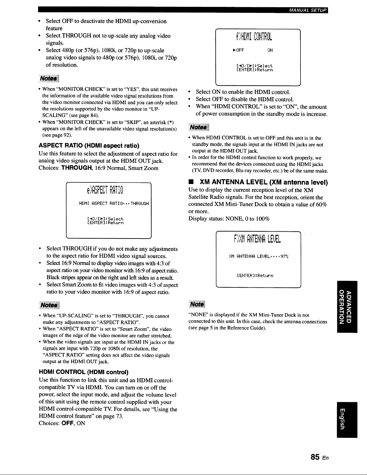
• Select OFF to deactivate the HDMI up-conversion
feature
• Select THROUGH not to up-scale any analog video
signals.
• Select 480p (or 576p), 1080i, or 720p to up-scale
analog video signals to 480p (or 576p), 1080i, or 720p
of resolution.
?tr-,i#1I/.,laI.'/_H #1,
¢)HDHICONTROL
I_OFF OH
[_]/[_]:Select
[ENTER]:ReLuPn
• When "MONITOR CHECK" is set to "YES", this unit receives
the information of the available video signal resolutions from
the video monitor connected via HDMI and you can only select
the resolutions supported by the video monitor in "UP-
SCALING" (see page 84).
• When "MONITOR CHECK" is set to "SKIP", an asterisk (*)
appears on the left of the unavailable video signal resolution(s)
(see page 92).
ASPECT RATIO (HDMI aspect ratio)
Use this feature to select the adjustment of aspect ratio for
analog video signals output at the HDMI OUT jack.
Choices: THROUGH, 16:9 Normal, Smart Zoom
. ,,bPEt;TRATIO
HDHI ASPECT RATIO. • •THROUGH
[_]/[m]:Select
[ENTER]:RetuPn
• Select THROUGH if you do not make any adjustments
to the aspect ratio for HDMI video signal sources.
• Select 16:9 Normal to display video images with 4:3 of
aspect ratio on your video monitor with 16:9 of aspect ratio.
Black stripes appear on the right and left sides as a result.
• Select Smart Zoom to fit video images with 4:3 of aspect
ratio to your video monitor with 16:9 of aspect ratio.
• When "UP-SCALING" is set to "THROUGH", you cannot
make any adjustments to "ASPECT RATIO".
• When "ASPECT RATIO" is set to "Smart Zoom", the video
images of the edge of the video monitor are rather stretched.
• When the video signals are input at the HDMI IN jacks or the
signals are input with 720p or 1080i of resolution, the
"ASPECT RATIO" setting does not affect the video signals
output at the HDMI OUT jack.
HDMI CONTROL (HDMI control)
Use this function to link this unit and an HDMI control-
compatible TV via HDMI. You can turn on or off the
power, select the input mode, and adjust the volume level
of this unit using the remote control supplied with your
HDMI control-compatible TV. For details, see "Using the
HDMI control feature" on page 73.
Choices: OFF, ON
• Select ON to enable the HDMI control.
• Select OFF to disable the HDMI control.
• When "HDMI CONTROL" is set to "ON", the amount
of power consumption in the standby mode is increase.
• When HDMI CONTROL is set to OFF and this unit is in the
standby mode, the signals input at the HDMI IN jacks are not
output at the HDMI OUT jack.
• In order for the HDMI control function to work properly, we
recommend that the devices connected using the HDMI jacks
(TV, DVD recorder, Blu-ray recorder, etc.) be of the same make.
• XM ANTENNA LEVEL (XM antenna level)
Use to display the current reception level of the XM
Satellite Radio signals. For the best reception, orient the
connected XM Mini-Tuner Dock to obtain a value of 60%
or more.
Display status: NONE, 0 to 100%
F)XHANTEIII,IALE!!EL
XH ANTENHA LEUEL .... 97%
[ENTER]:RetuPn
"NONE" is displayed if the XM Mini-Tuner Dock is not
connected to this unit. In this case, check the antenna connections
(see page 5 in the Reference Guide).
I
85 En
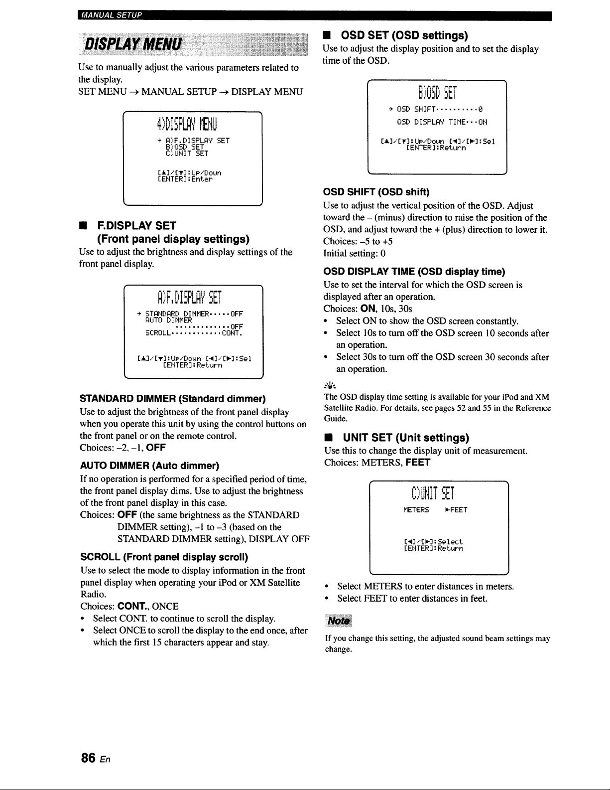
Use to manually adjust the various parameters related to
the display.
SET MENU _ MANUAL SETUP --->DISPLAY MENU
4',:'DISPLA"/MENU
÷ A)F.DISPLAY SET
B)OSD SET
C)UHIT SET
[i] / [_r] : UP/Do_Jn
[ ENTER ] : Enter
• F.DISPLAY SET
(Front panel display settings)
Use to adjust the brightness and display settings of the
front panel display.
Q>F,DISPLQYSET
÷ STANDARD DIMMER ..... OFF
AUTO DIMMER
............. OFF
SCROLL ............ CONT.
[_]/[IF] : UP/Do_Jn [_I]/[I_] : Sel
[ENTER] : Return
STANDARD DIMMER (Standard dimmer)
Use to adjust the brightness of the front panel display
when you operate this unit by using the control buttons on
the front panel or on the remote control.
Choices: -2, -1, OFF
AUTO DIMMER (Auto dimmer)
If no operation is performed for a specified period of time,
the front panel display dims. Use to adjust the brightness
of the front panel display in this case.
Choices: OFF (the same brightness as the STANDARD
DIMMER setting), -1 to -3 (based on the
STANDARD DIMMER setting), DISPLAY OFF
SCROLL (Front panel display scroll)
Use to select the mode to display information in the front
panel display when operating your iPod or XM Satellite
Radio.
Choices: CONT., ONCE
• Select CONT. to continue to scroll the display.
• Select ONCE to scroll the display to the end once, after
which the first 15 characters appear and stay.
• OSD SET (OSD settings)
Use to adjust the display position and to set the display
time of the OSD.
ri'r,
B,U:,DSET
÷ OSD SHIFT .......... 0
OSD DISPLAV TIME,, ,ON
[_]/[_] : UP/Down [_I]/[l_] : Sel
[ENTER ] : Return
OSD SHIFT (OSD shift)
Use to adjust the vertical position of the OSD. Adjust
toward the - (minus) direction to raise the position of the
OSD, and adjust toward the + (plus) direction to lower it.
Choices: -5 to +5
Initial setting: 0
OSD DISPLAY TIME (OSD display time)
Use to set the interval for which the OSD screen is
displayed after an operation.
Choices: ON, 10s, 30s
• Select ON to show the OSD screen constantly.
• Select 10s to turn offthe OSD screen 10 seconds after
an operation.
• Select 30s to turn off the OSD screen 30 seconds after
an operation.
..,_,..
The OSDdisplay time setting is available for your iPod andXM
Satellite Radio. For details, see pages 52 and 55 in the Reference
Guide.
• UNIT SET (Unit settings)
Use this to change the display unit of measurement.
Choices: METERS, FEET
C)IJNtTSET
METERS _FEET
[41]/[I_]: Select
[ ENTER ] : Return
• Select METERS to enter distances in meters.
• Select FEET to enter distances in feet.
I TI
If you change this setting, the adjustedsound beam settings may
change.
86 En
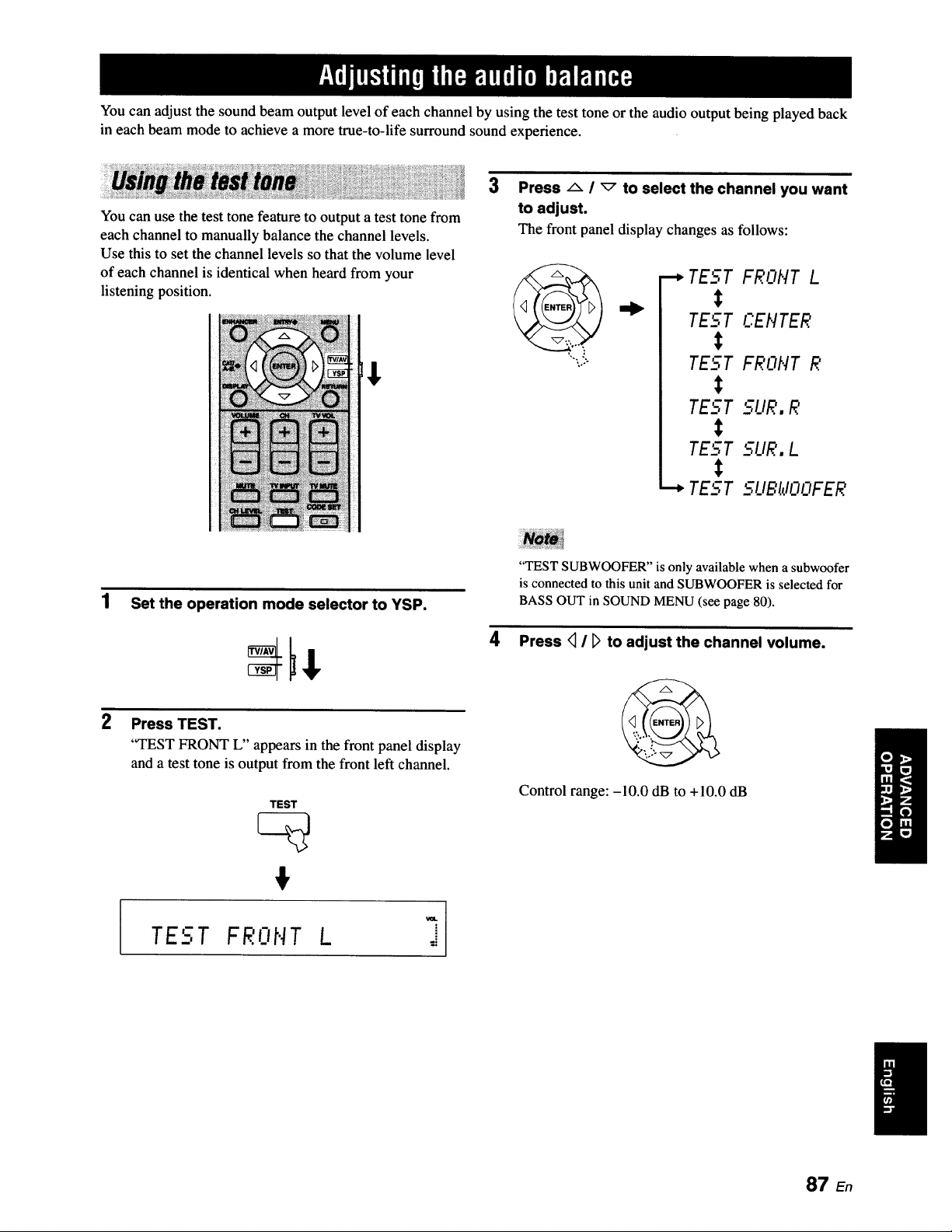
You can adjust the sound beam output level of each channel by using the test tone or the audio output being played back
in each beam mode to achieve a more true-to-life surround sound experience.
You can use the test tone feature to output a test tone from
each channel to manually balance the channel levels.
Use this to set the channel levels so that the volume level
of each channel is identical when heard from your
listening position.
[$
3
Press A / _ to select the channel you want
to adjust.
The front panel display changes as follows:
•-_ TEST FRONT L
t
TEL-.T CEIlTER
TEST FRONT R
TEST 5L/R. R
TEST 5UR. L
•"-* TEST __.UBtlOOFER
1 Set the operation mode selector to YSP.
2
Press TEST.
"TEST FRONT L" appears in the front panel display
and a test tone is output from the front left channel.
TEST
#
"TEST SUBWOOFER" is only available when a subwoofer
is connected to this unit and SUBWOOFER is selected for
BASS OUT in SOUND MENU (see page 80).
Press <_/ _ to adjust the channel volume.
Control range: -10.0 dB to +10.0 dB
TEST FRONT L =
87 En
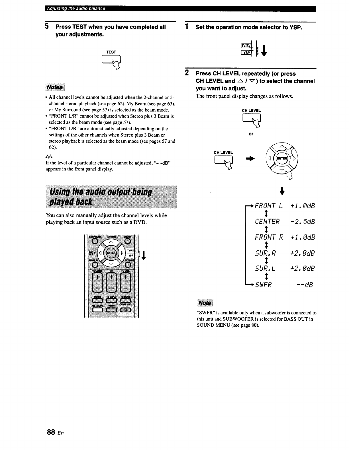
IT_lS_ .a. ml. r-_..rar*l,mY. |1(oL_
5 Press TEST when you have completed all
your adjustments.
TEST
• All channel levels cannot be adjusted when the 2-channel or 5-
channel stereo playback (see page 62), My Beam (see page 63),
or My Surround (see page 57) is selected as the beam mode.
• "FRONT L/R" cannot be adjusted when Stereo plus 3 Beam is
selected as the beam mode (see page 57).
• "FRONT L/R" are automatically adjusted depending on the
settings of the other channels when Stereo plus 3 Beam or
stereo playback is selected as the beam mode (see pages 57 and
62).
If the level of a particular channel cannot be adjusted, "- -dB"
appears in the front panel display.
You can also manually adjust the channel levels while
playing back an input source such as a DVD.
1 Set the operation mode selector to YSP.
2
Press CH LEVEL repeatedly (or press
CH LEVEL and A i _) to select the channel
you want to adjust.
The front panel display changes as follows.
CH LEVEL
CH LEVEL
or
,.,,
....,FRONT L +1, OdB
t
C.EHTER -2, 5dB
t
FRONT R +1, 0dB
t
SLIR, R +2, OdB
t
5UR, L +2. OdB
t
5;IJFR - - dB
"SWFR" is available only when a subwoofer is connected to
this unit and SUBWOOFER is selected for BASS OUT in
SOUND MENU (see page 80).
88 En
3 Press _ / [_ to adjust the channel volume.
Control range: -10.0 dB to +10.0 dB
4 Wait for a few seconds without operating this
unit when you have completed your
adjustment.
ip#nlk'fltmroatnl_:.lltottel;'_r.ltt_"
• All channel levels cannot be adjusted when the 2-channel or 5-
channel stereo playback (see page 62), or My Surround (see
page 57) is selected as the beam mode.
• "FRONT L/R" cannot be adjusted when Stereo plus 3 Beam is
selected as the beam mode (see page 57).
• Only CENTER can be adjusted when My Beam is selected as
the beam mode (see page 63).
• "FRONT L/R" are automatically adjusted depending on the
settings of the other channels when Stereo plus 3 Beam or
stereo playback is selected as the beam mode (see pages 57 and
62).
..,#..
If the level of a particular channel cannot be adjusted, "- -dB"
appears in the front panel display.
89 E,
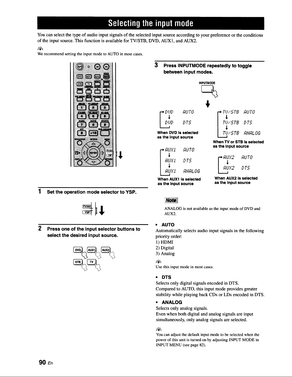
You can select the type of audio input signals of the selected input source according to your preference or the conditions
of the input source. This function is available for TV/STB, DVD, AUX1, and AUX2.
We recommend setting the input mode to AUTO in most cases.
3 Press INPUTMODE repeatedly to toggle
between input modes.
1 Set the operation mode selector to YSP.
INPUTMODE
%
F
When DVD is selected ITIJ.."STB P,flALOG
as the Input source
i ,
When TV or STB is selected
asthe inputsource
I I:ILI,_'I RUTO
I_X1 DT5 F P,_X2 AUTO
i P,L,IXl ANP,LOG I AU,,X2 DT5
When AUX1 is selected When AUX2 is selected
as the input source as the input source
ANALOG is not available as the input mode of DVD and
AUX2.
Press one of the input selector buttons to
select the desired input source.
',.. J '... ,'
;,,- ,.o,
• AUTO
Automatically selects audio input signals in the following
priority order:
1) HDMI
2) Digital
3) Analog
_%'._
Use this input mode in most cases.
• DTS
Selects only digital signals encoded in DTS.
Compared to AUTO, this input mode provides greater
stability while playing back CDs or LDs encoded in DTS.
• ANALOG
Selects only analog signals.
Even when both digital and analog signals are input
simultaneously, only analog signals are selected.
You can adjust the default input mode to be selected when the
powerof this unit is turnedon by adjusting INPUT MODE in
INPUT MENU (see page 82).
90 En
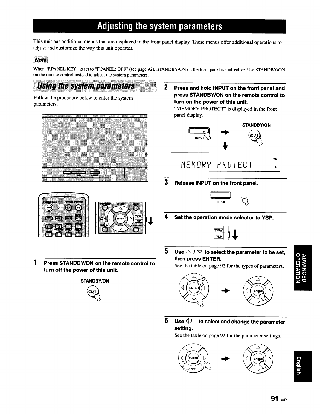
This unit has additional menus that are displayed in the front panel display. These menus offer additional operations to
adjust and customize the way this unit operates.
When "F.PANEL KEY" is set to "F.PANEL: OFF" (see page 92), STANDBY/ON on the front panel is ineffective. Use STANDBY/ON
on the remote control instead to adjust the system parameters.
Follow the procedure below to enter the system
parameters.
2
Press and hold INPUT on the front panel and
press STANDBY/ON on the remote control to
turn on the power of this unit.
"MEMORY PROTECT" is displayed in the front
panel display.
STANDBY/ON
' '17
r'lEr'lORt,' FR. TEF.:T =i
3 Release INPUT on the front panel.
INPUT _>
4 Set the operation mode selector to YSP.
1
Press STANDBY/ON on the remote control to
turn off the power of this unit.
STANDBY/ON
5
Use _ I _" to select the parameter to be set,
then press ENTER.
See the table on page 92 for the types of parameters.
6
Use <_I D to select and change the parameter
setting.
See the table on page 92 for the parameter settings.
91 En
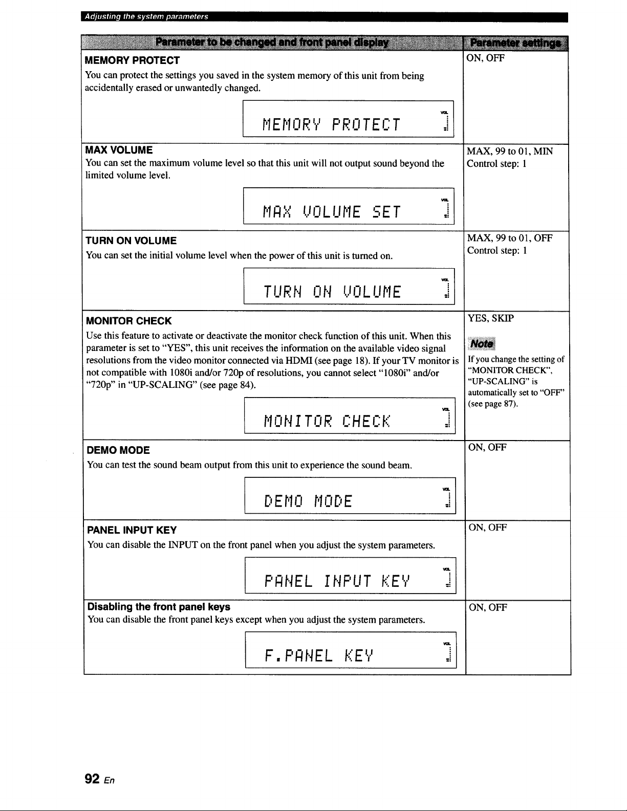
ON, OFF
MEMORY PROTECT
You can protect the settings you saved in the system memory of this unit from being
accidentally erased or unwantedly changed.
, ,l]'Y_IE_I.R PROTECT
MAX VOLUME
You can set the maximum volume level so that this unit will not output sound beyond the
limited volume level.
"' UOLIIr.IESETr,IR,,.,. .
TURN ON VOLUME
You can set the initial volume level when the power of this unit is turned on.
MONITOR CHECK
i
=i
VaL
J
_mL
TURN ON VOLUHE J
Use this feature to activate or deactivate the monitor check function of this unit. When this
parameter is set to "YES", this unit receives the information on the available video signal
resolutions from the video monitor connected via HDMI (see page 18). If your TV monitor is
not compatible with 1080i and/or 720p of resolutions, you cannot select "1080i" and/or
"720p" in "UP-SCALING" (see page 84).
HONITOR C'HECK
DEMO MODE
You can test the sound beam output from this unit to experience the sound beam.
=i
C.,Er,10HO[:,E
PANEL INPUT KEY
You can disable the INPUT on the front panel when you adjust the system parameters.
PI:INELINPUT KEY
Disabling the front panel keys
You can disable the front panel keys except when you adjust the system parameters.
F, PANEL KEY
=i
=i
MAX, 99 to 01, MIN
Control step: 1
MAX, 99 to 01, OFF
:Control step: 1
YES, SKIP
If you change the setting of
"MONITOR CHECK",
"UP-SCALING" is
automatically set to "OFF"
(see page 87).
ON, OFF
ON, OFF
ON, OFF
92 En
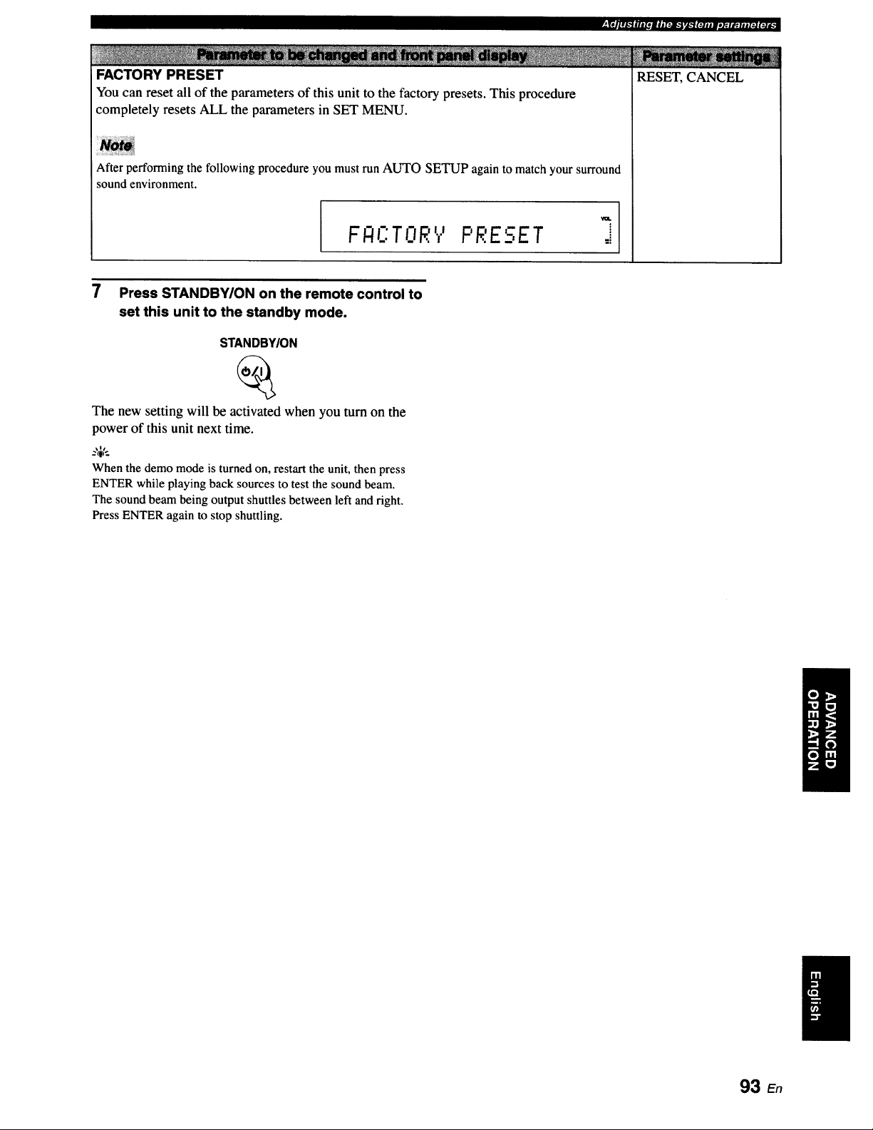
RESET, CANCEL
FACTORY PRESET
You can reset all of the parameters of this unit to the factory presets. This procedure
completely resets ALL the parameters in SET MENU.
After performing the following procedure you must run AUTO SETUP again to match your surround
sound environment.
IF E:TORV PRESET
7 Press STANDBY/ON on the remote control to
set this unit to the standby mode.
STANDBY/ON
The new setting will be activated when you turn on the
power of this unit next time.
_%'..
When the demo mode is turned on, restart the unit, then press
ENTER while playing back sourcesto test the sound beam.
The sound beam being output shuttles between left and right.
Press ENTER again to stop shuttling.
93 En
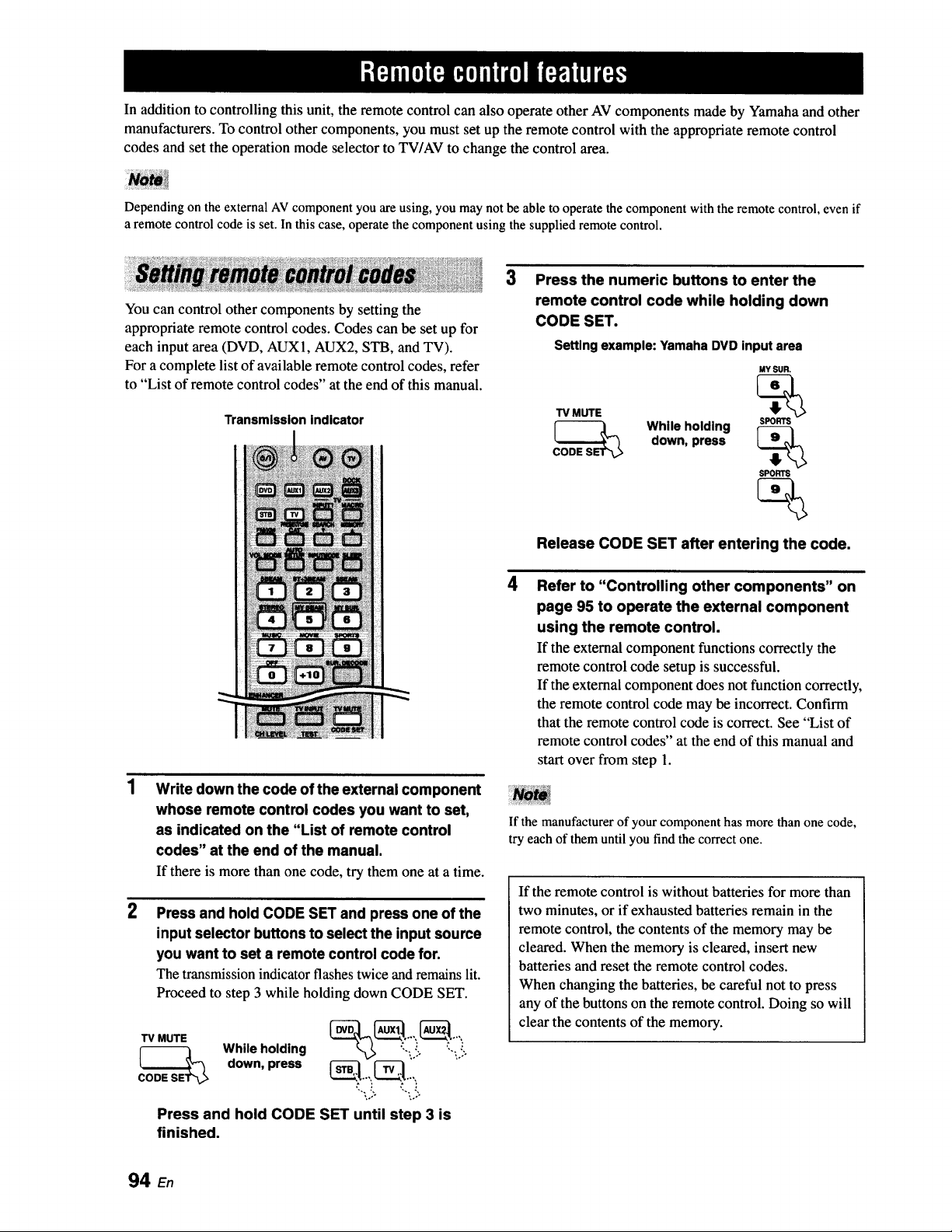
In addition to controlling this unit, the remote control can also operate other AV components made by Yamaha and other
manufacturers. To control other components, you must set up the remote control with the appropriate remote control
codes and set the operation mode selector to TV/AV to change the control area.
Depending on the external AV component you are using, you may not be able to operate the component with the remote control, even if
a remote control code is set. In this case, operate the component using the supplied remote control.
You can control other components by setting the
appropriate remote control codes. Codes can be set up for
each input area (DVD, AUX1, AUX2, STB, and TV).
For a complete list of available remote control codes, refer
to "List of remote control codes" at the end of this manual.
Transmission indicator
2
Write down the code of the external component
whose remote control codes you want to set,
as indicated on the "List of remote control
codes" at the end of the manual.
If there is more than one code, try them one at a time.
Press and hold CODE SET and press one of the
input selector buttons to select the input source
you want to set a remote control code for.
The transmission indicator flashes twice and remains lit.
Proceed to step 3 while holding down CODE SET.
CODE__ s While holding
down, press _..,,, _--_,.,:
*,." %."
Press and hold CODE SET until step 3 is
finished.
3
4
Press the numeric buttons to enter the
remote control code while holding down
CODE SET.
Setting example: Yamaha DVD input area
TV MUTE
CODERS While holding
down, press
MY SUP..
%
SPOW_
%
SPORTS
Release CODE SET after entering the code.
Refer to "Controlling other components" on
page 95 to operate the external component
using the remote control.
If the external component functions correctly the
remote control code setup is successful.
If the external component does not function correctly,
the remote control code may be incorrect. Confirm
that the remote control code is correct. See "List of
remote control codes" at the end of this manual and
start over from step 1.
If the manufacturer of your component has more than one code,
try each of them until you find the correct one.
If the remote control is without batteries for more than
two minutes, or if exhausted batteries remain in the
remote control, the contents of the memory may be
cleared. When the memory is cleared, insert new
batteries and reset the remote control codes.
When changing the batteries, be careful not to press
any of the buttons on the remote control. Doing so will
clear the contents of the memory.
94 En
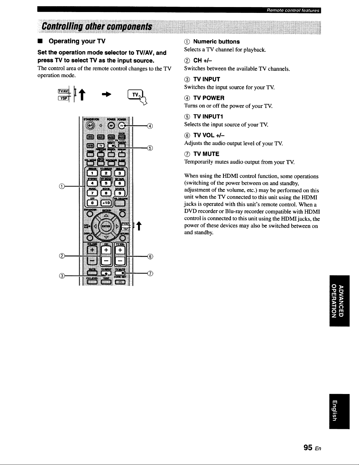
• Operating your TV
Set the operation mode selector to TV/AV, and
press TV to select TV as the input source.
The controlarea of the remote controlchangesto theTV
operation mode.
®
Q
Numeric buttons
Selects a TV channel for playback.
CH+I-
Switches between the available TV channels.
® TV INPUT
Switches the input source for your TV.
TV POWER
Turns onor off the power of your TV.
TV INPUT1
Selectsthe input source of your TV.
TV VOL +/-
Adjusts the audio output level of your TV.
O TV MUTE
Temporarily mutes audio output from your TV.
When using the HDMI control function, some operations
(switching of the power between on and standby,
adjustment of the volume, etc.) may be performed on this
unit when the TV connected to this unit using the HDMI
jacks is operated with this unit's remote control. When a
DVD recorder or Blu-ray recorder compatible with HDMI
control is connected to this unit using the HDMIjacks, the
power of these devices may also be switched between on
and standby.
95 En
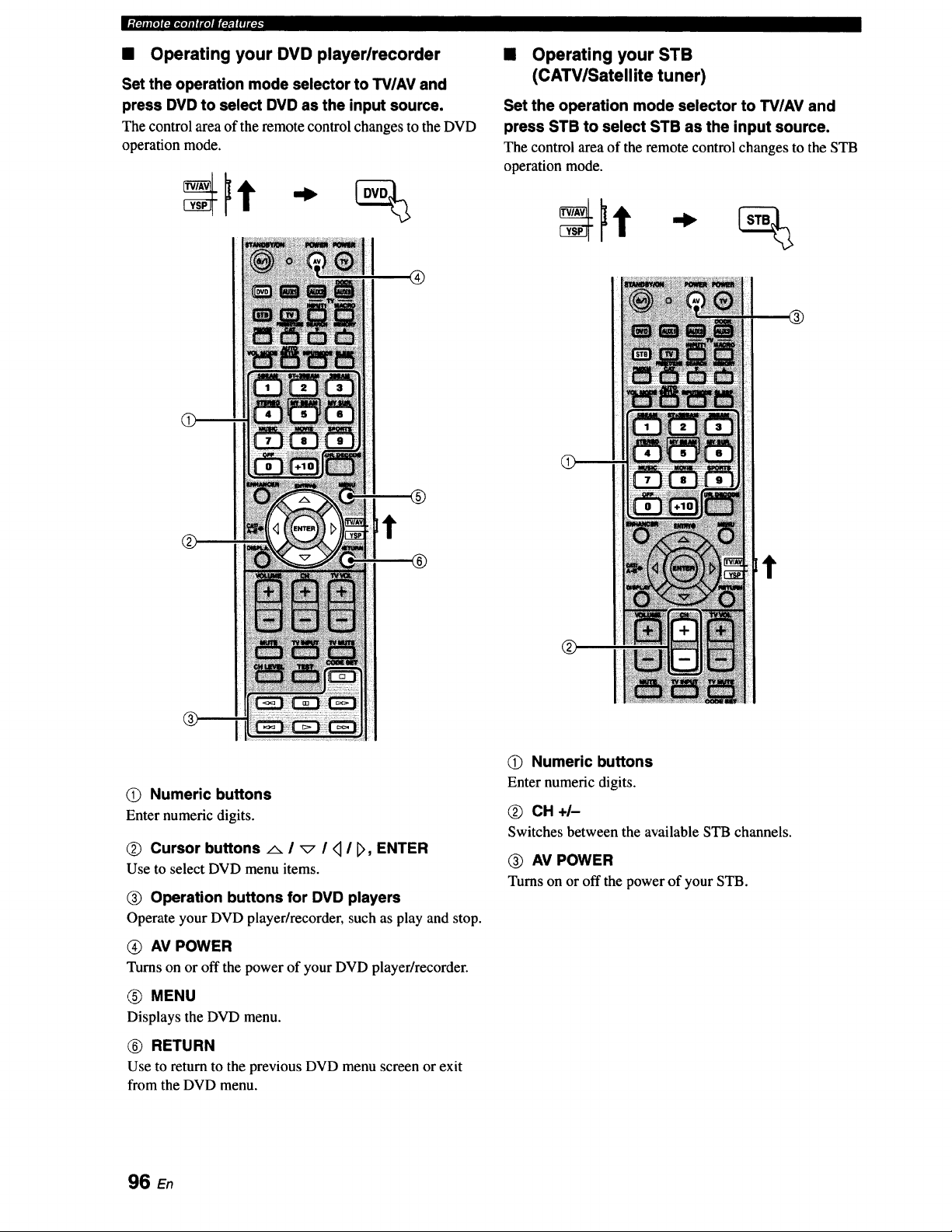
• Operating your DVD player/recorder
Set the operation mode selector to TV/AV and
press DVD to select DVD as the input source.
The control area of the remote control changes to the DVD
operation mode.
®
®
• Operating your STB
(CATV/Satellite tuner)
Set the operation mode selector to TV/AV and
press STB to select STB as the input source.
The control area of the remote control changes to the STB
operation mode.
t
®
O) Numeric buttons
Enter numeric digits.
Q Cursor buttons _ I _ I q I _, ENTER
Use to select DVD menu items.
Operation buttons for DVD players
Operate your DVD player/recorder, such as play and stop.
AV POWER
Turns on or off the power of your DVD player/recorder.
(_) MENU
Displays the DVD menu.
(_) RETURN
Use to return to the previous DVD menu screen or exit
from the DVD menu.
O) Numeric buttons
Enter numeric digits.
CH+I-
Switches between the available STB channels.
O AV POWER
Turns on or off the power of your STB.
96 E.
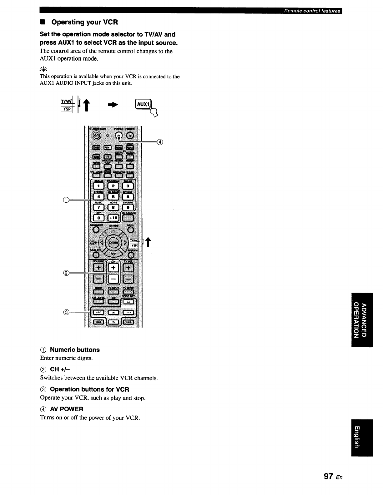
• Operating your VCR
Set the operation mode selector to TVIAV and
press AUX1 to select VCR as the input source.
The control area of the remote control changes to the
AUX1 operation mode.
This operation is available when your VCR is connected to the
AUX1 AUDIOINPUT jacks on this unit.
®
Lt
0) Numeric buttons
Enter numeric digits.
@ CH+I-
Switches between the available VCR channels.
_) Operation buttons for VCR
Operate your VCR, such as play and stop.
(_ AV POWER
Turns on or off the power of your VCR.
"[:-]ll[O](:i[tiOllllte]|l';_]_ll[_:_
97 En
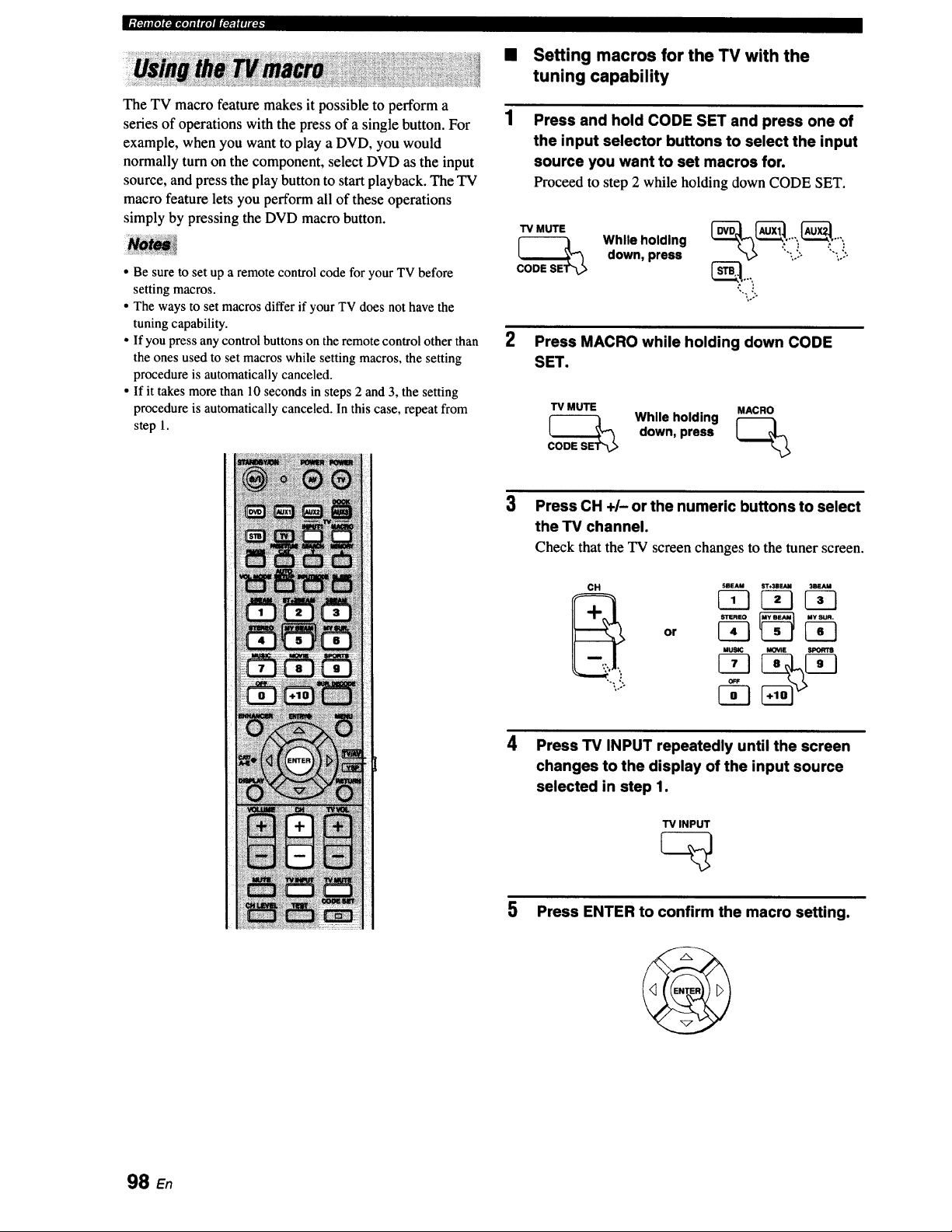
_(*-.li|[O](:_[KIIIII'_I|!II'.JJ
The TV macro feature makes it possible to perform a
series of operations with the press of a single button. For
example, when you want to play a DVD, you would
normally turn on the component, select DVD as the input
source, and press the play button to start playback. The TV
macro feature lets you perform all of these operations
simply by pressing the DVD macro button.
• Be sure to set up a remote control code for your TV before
setting macros.
• The ways to set macros differ if your TV does not have the
tuning capability.
• If you press any control buttons on the remote control other than
the ones used to set macros while setting macros, the setting
procedure is automatically canceled.
• If it takes more than 10 seconds in steps 2 and 3, the setting
procedure is automatically canceled. In this case, repeat from
step 1.
Setting macros for the TV with the
tuning capability
Press and hold CODE SET and press one of
the input selector buttons to select the input
source you want to set macros for.
Proceed to step 2 while holding down CODE SET.
TV MUTE
w e o0n0%
down, press ':",,.!; '_'_.!:
2 Press MACRO while holding down CODE
SET.
TV MUTE MACRO
CODE__SE While holding _>
down,press
3
Press CH +/- or the numeric buttons to select
the TV channel.
Check that the TV screen changes to the tuner screen.
CH SBFJ,U ST+3BF.N_ 3ira-AM
STEREO MY SUR.
MUSIC MOViI_ SPORTS
4
Press TV INPUT repeatedly until the screen
changes to the display of the input source
selected in step 1.
TV INPUT
5
Press ENTER to confirm the macro setting.
98
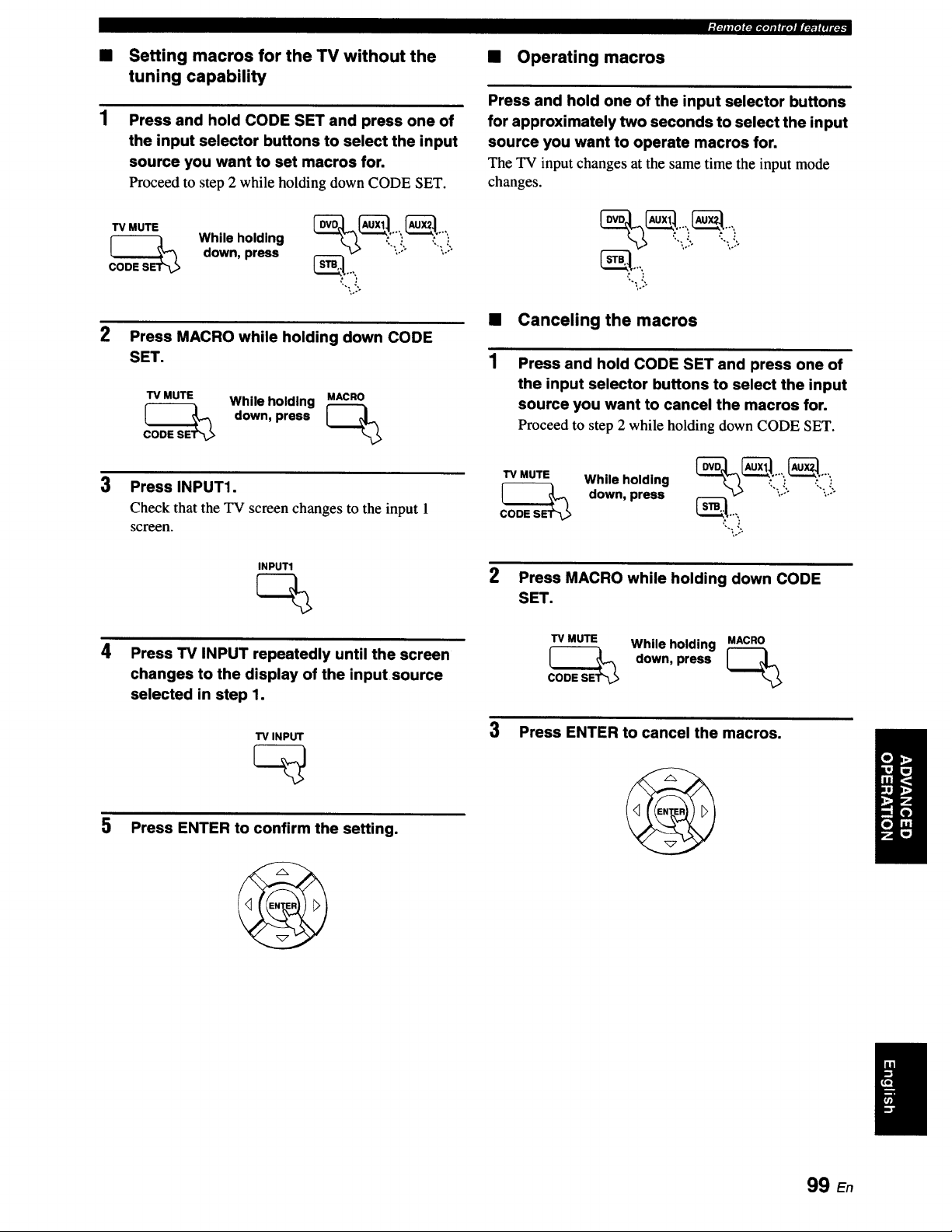
• Setting macros for the TV without the
tuning capability
Press and hold CODE SET and press one of
the input selector buttons to select the input
source you want to set macros for.
Proceed to step 2 while holding down CODE SET.
TVMUTE While holding __'"" _'""
CODE__S down, press _..,, '_'\-!: ':'",.!:
2
Press MACRO while holding down CODE
SET.
TV MUTE While holding MACRO
CODE__SE down, press _>
• Operating macros
_f=/n JJre.!t-=lr_olm i r t=JJ_ i_l_, _
Press and hold one of the input selector buttons
for approximately two seconds to select the input
source you want to operate macros for.
The TV inputchangesat the sametime the input mode
changes.
,..-
• Canceling the macros
1
Press and hold CODE SET and press one of
the input selector buttons to select the input
source you want to cancel the macros for.
Proceed to step 2 while holding down CODE SET.
TV MUTE While holding %_,'.'i i!;_'i i!:
3 Press INPUT1. _ down,press
Check that the TV screen changes to the input 1 _..,,
screen. ',.,:,
INPUT1
4
Press TV INPUT repeatedly until the screen
changes to the display of the input source
selected in step 1.
TV INPUT
5 Press ENTER to confirm the setting.
2 Press MACRO while holding down CODE
SET.
TV MUTE While holding MACRO
down,press
3 Press ENTER to cancel the macros.
99 En
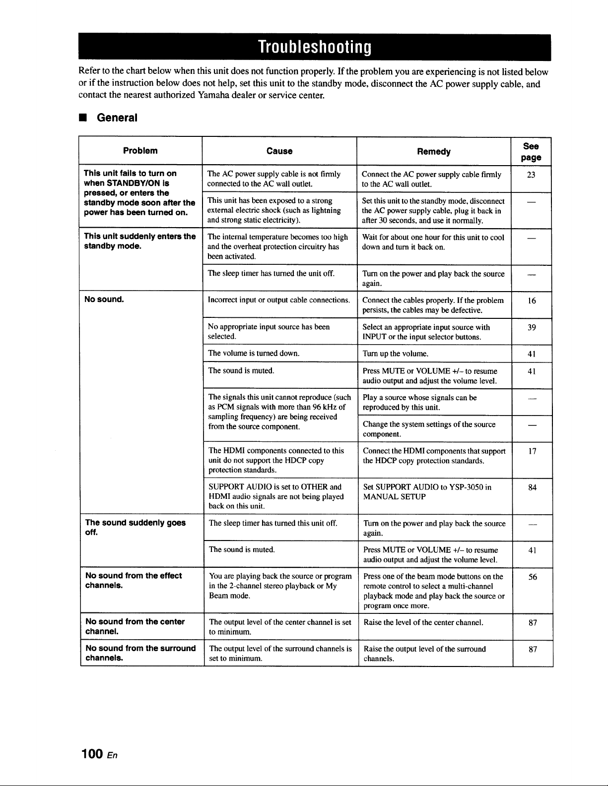
Refer to the chart below when this unit does not function properly. If the problem you are experiencing is not listed below
or if the instruction below does not help, set this unit to the standby mode, disconnect the AC power supply cable, and
contact the nearest authorized Yamaha dealer or service center.
• General
This unit fails to turn on
when STANDBY/ON Is
pressed, or enters the
standby mode soon after the
power has been turned on.
See
Problem Cause Remedy
page
23
This unit suddenly enters the
standby mode.
No sound.
The sound suddenly goes
off.
The AC power supply cable is not firmly
connected to the AC wall outlet.
This unit has been exposed to a strong
external electric shock (such as lightning
and strong static electricity),
The internal temperature becomes too high
and the overheat protection circuitry has
been activated.
The sleep timer has turned the unit off.
Incorrect input or output cable connections.
Connect the AC power supply cable firmly
to the AC wall outlet.
Set this unit to the standby mode, disconnect
the AC power supply cable, plug it back in
after 30 seconds, and use it normally.
Wait for about one hour for this unit to cool
down and turn it back on.
Turn on the power and play back the source
again.
Connect the cables properly. If the problem
persists, the cables may be defective.
No appropriate input source has been Select an appropriate input source with
selected. INPUT or the input selector buttons.
The volume is turned down. Turn up the volume.
The sound is muted. Press MUTE or VOLUME +/- to resume
audio output and adjust the volume level.
The signals this unit cannot reproduce (such
as PCM signals with more than 96 kHz of
sampling frequency) are being received
from the source component.
The HDMI components connected to this
unit do not support the HDCP copy
protection standards.
SUPPORT AUDIO is set to OTHER and
HDMI audio signals are not being played
back on this unit.
The sleep timer has turned this unit off.
Play a source whose signals can be
reproduced by this unit.
Change the system settings of the source
component.
Connect the HDMI components that support
the HDCP copy protection standards.
Set SUPPORT AUDIO to YSP-3050 in
MANUAL SETUP
16
39
41
41
Turn on the power and play back the source
again.
Press MUTE or VOLUME +/- to resume
audio output and adjust the volume level.
Press one of the beam mode buttons on the
remote control to select a multi-channel
playback mode and play back the source or
program once more.
17
84
The sound is muted. 41
No sound from the effect You are playing back the source or program 56
channels, in the 2-channel stereo playback or My
Beam mode.
No sound from the center The output level of the center channel is set Raise the level of the center channel. 87
channel, to minimum.
No sound from the surround The output level of the surround channels is Raise the output level of the surround 87
channels, set to minimum, channels.
100 E.
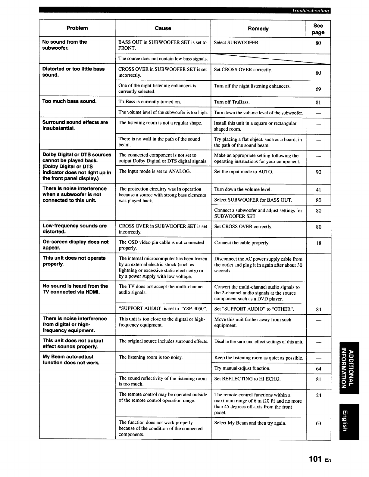
fg.lqq[_-'llp,[*JuJt,
Problem Cause See
page
No sound from the 80
subwoofer.
Distorted or too little bass
sound.
Too much bass sound.
Surround sound effects are
insubstantial.
Dolby Digital or DTS sources
cannot be played back.
(Dolby Digital or DTS
indicator does not light up in
the front panel display.)
There is noise interference
when a subwoofer is not
connected to this unit.
Low-frequency sounds are
distorted,
On-screen display does not
appear.
This unit does not operate
properly.
No sound is heard from the
TV connected via HDMI.
There is noise interference
from digital or high-
frequency equipment.
This unit does not output
effect sounds properly.
My Beam auto-adjust
function does not work.
BASS OUT in SUBWOOFER SET is set to
FRONT.
The source does not contain low bass signals.
CROSS OVER in SUBWOOFER SET is set
incorrectly.
One of the night listening enhancers is
currently selected.
TmBass is currently turned on.
The volume level of the subwoofer is too high.
The listening room is not a regular shape.
There is no wall in the path of the sound
beam.
The connected component is not set to
output Dolby Digital or DTS digital signals.
The input mode is set to ANALOG.
The protection circuitry was in operation
because a source with strong bass elements
was played back.
CROSS OVER in SUBWOOFER SET is set
incorrectly.
The OSD video pin cable is not connected
properly.
The internal microcomputer has been frozen
by an external electric shock (such as
lightning or excessive static electricity) or
by a power supply with low voltage.
The TV does not accept the multi-channel
audio signals.
"SUPPORT AUDIO" is set to "YSP-3050".
This unit is too close to the digital or high-
frequency equipment.
The original source includes surround effects.
The listening room is too noisy.
The sound reflectivity of the listening room
is too much.
The remote control may be operated outside
of the remote control operation range.
The function does not work properly
because of the condition of the connected
components.
Remedy
Select SUBWOOFER.
Set CROSS OVER correctly.
Turn off the night listening enhancers.
Turn off TmBass.
Turn down the volume level of the subwoofer.
Install this unit in a square or rectangular
shaped room.
Try placing a flat object, such as a board, in
the path of the sound beam.
Make an appropriate setting following the
operating instructions for your component.
Set the input mode to AUTO.
Turn down the volume level.
Select SUBWOOFER for BASS OUT.
Connect a subwoofer and adjust settings for
SUBWOOFER SET.
Set CROSS OVER correctly.
Connect the cable properly.
Disconnect the AC power supply cable from
the outlet and plug it in again after about 30
seconds.
Convert the multi-channel audio signals to
the 2-channel audio signals at the source
component such as a DVD player.
Set "SUPPORT AUDIO" to "OTHER".
Move this unit farther away from such
equipment.
Disable the surround effect settings of this unit.
Keep the listening room as quiet as possible.
Try manual-adjust function.
Set REFLECTING to H1 ECHO.
The remote control functions within a
maximum range of 6 m (20 ft) and no more
than 45 degrees off-axis from the front
panel.
Select My Beam and then try again.
80
69
81
q
90
41
80
80
80
18
84
64
81
24
63
101 En
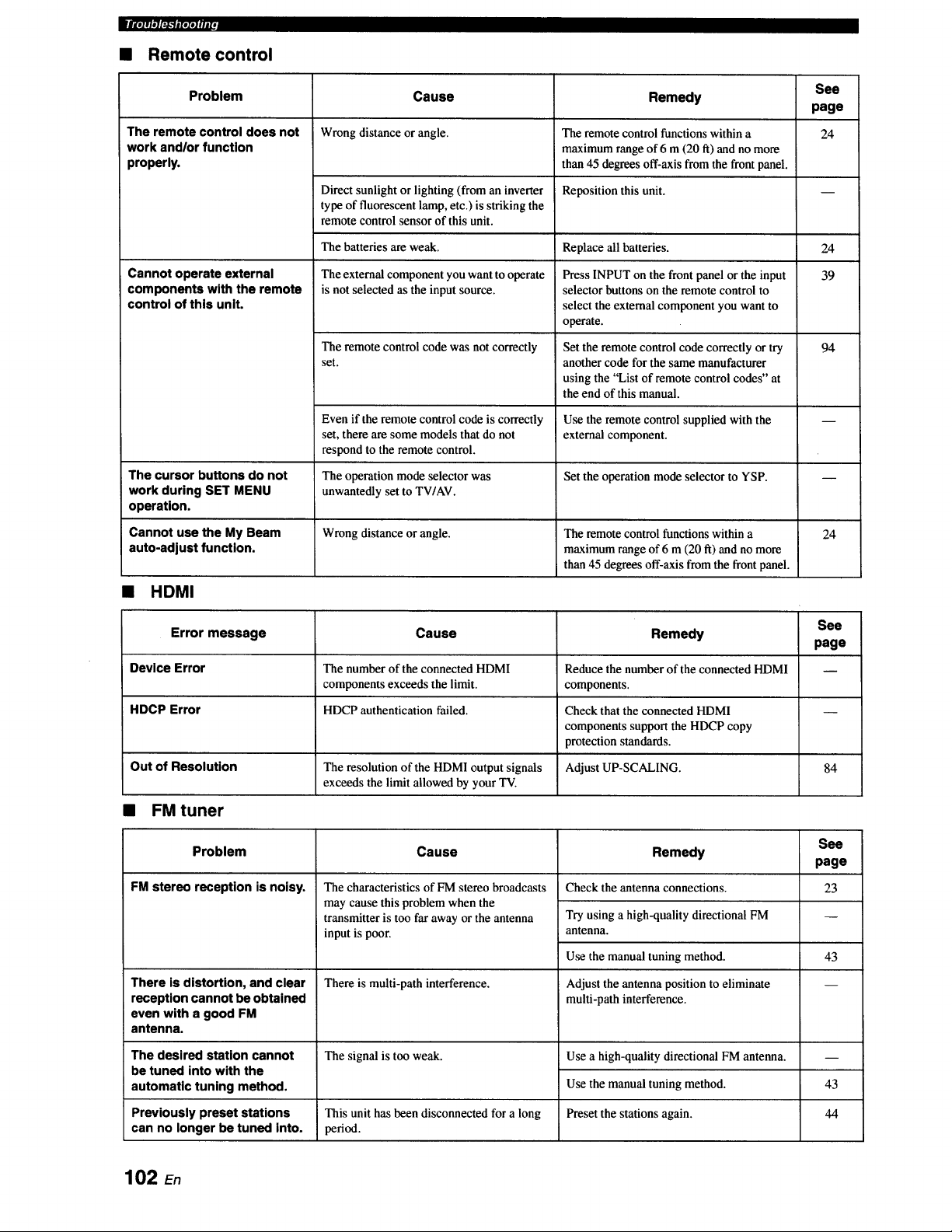
mllolrleT_'_##1ld
• Remote control
Problem Cause See
page
Wrong distance or angle. 24
The remote control does not
work and/or function
properly.
Cannot operate external
components with the remote
control of this unit.
Direct sunlight or lighting (from an inverter
type of fluorescent lamp, etc.) is striking the
remote control sensor of this unit.
The batteries are weak.
The external component you want to operate
is not selected as the input source.
The remote control code was notcorrectly
set.
Even if the remote control code is correctly
set, there are some models that do not
respond to the remote control.
Remedy
The remote control functions within a
maximum range of 6 m (20 ft) and no more
than 45 degrees off-axis from the front panel.
Reposition this unit.
Replace all batteries.
Press INPUT on the front panel or the input
selector buttons on the remote control to
select the external component you want to
operate.
Set the remote control code correctly or try
another code for the same manufacturer
using the "List of remote control codes" at
the end of this manual.
Use the remote control supplied with the
external component.
24
39
94
The cursor buttons do not The operation mode selector was Set the operation mode selector to YSP. --
work during SET MENU unwantedly set to TWAV.
operation.
Cannot use the My Beam Wrong distance or angle. The remote control functions within a 24
auto-adjust function, maximum range of 6 m (20 ft) and no more
than 45 degrees off-axis from the front panel.
• HDMI
See
Error message Cause Remedy
page
Device Error The number of the connected HDMI Reduce the number of the connected HDMI --
components exceeds the limit, components.
HDCP Error HDCP authentication failed. Check that the connected HDMI --
components support the HDCP copy
protection standards.
Out of Resolution The resolution of the HDMI output signals Adjust UP-SCALING. 84
exceeds the limit allowed by your TV.
• FM tuner
Problem Cause See
page
FM stereo reception is noisy. 23
The characteristics of FM stereo broadcasts
may cause this problem when the
transmitter is too far away or the antenna
input is poor.
There is multi-path interference.
The signal is too weak.
There is distortion, and clear
reception cannot be obtained
even with a good FM
antenna.
Remedy
Check the antenna connections.
Try using a high-quality directional FM
antenna.
Use the manual tuning method.
Adjust the antenna position to eliminate
multi-path interference.
Use a high-quality directional FM antenna.
Use the manual tuning method.
Preset the stations again.
The desired station cannot
be tuned into with the
automatic tuning method.
Previously preset stations This unit hasbeendisconnectedfor a long
can no longer be tuned into. period.
43
43
44
102 En
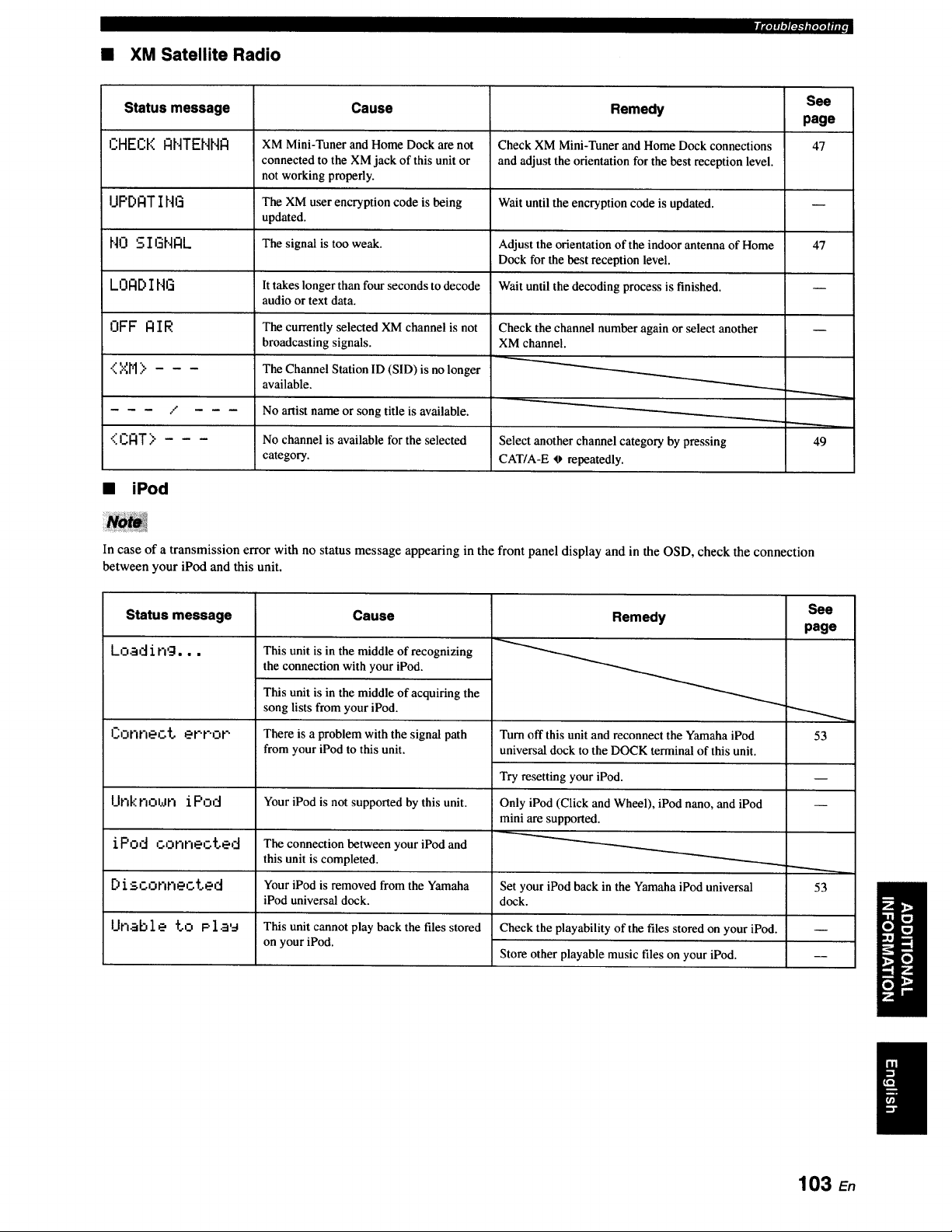
• XM Satellite Radio
|_*II, l,*Jg_*'ll[eZeJllJI,
Status message Cause See
page
CHECK ANTENNA XM Mini-Tuner and Home Dock are not 47
connected to the XM jack of this unit or
not working properly.
I.IPDATI NG The XM u_r encryption code is being
updated.
NO S 1171HIZlL The signal is too weak. 47
LOAD ING
OFF AIR
<XM>
/
<CAT> - - -
It takes longer than four seconds to decode
audio or text data.
The currently selected XM channel is not
broadcasting signals.
The Channel Station ID (SID) is no longer
available.
No artist name or song title is available.
No channel is available for the selected
category.
Remedy
Check XM Mini-Tuner and Home Dock connections
and adjust the orientation for the best reception level.
Wait until the encryption code is updated.
Adjust the orientation of the indoor antenna of Home
Dock for the best reception level.
Wait until the decoding process is finished.
Check the channel number again or ,select another
XM channel.
Select another channel category by pressing
CAT/A-E _ repeatedly.
• iPod
49
In case of a transmission error with no status message appearing in the front panel display and in the OSD, check the connection
between your iPod and this unit.
Status message
Load ing...
I_;onrlect error
Unknoun iPod
iPod connected
Disconnected
Unable to Plau
Cause
This unit is in the middle of recognizing
the connection with your iPod.
This unit is in the middle of acquiring the
song lists from your iPod.
There is a problem with the signal path
from your iPod to this unit.
Your iPod is not supported by this unit.
Remedy
Turn off this unit and reconnect the Yamaha iPod
universal dock to the DOCK terminal of this unit.
Try resetting your iPod.
Only iPod (Click and Wheel), iPod nano, and iPod
mini are supported.
See
page
".-,....,
53
The connection between your iPod and
this unit is completed.
Your iPod is removed from the Yamaha 53
iPod universal dock.
This unit cannot play back the files stored
on your iPod.
Set your iPod back in the Yamaha iPod universal
dock.
Check the playability of the files stored on your iPod.
Store other playable music files on your iPod.
103 En
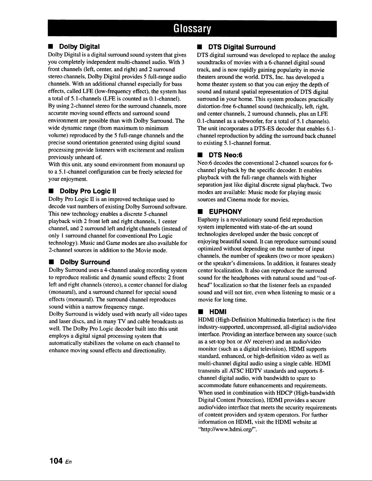
• Dolby Digital
Dolby Digital is a digital surround sound system that gives
you completely independent multi-channel audio. With 3
front channels (left, center, and right) and 2 surround
stereo channels, Dolby Digital provides 5 full-range audio
channels. With an additional channel especially for bass
effects, called LFE (low-frequency effect), the system has
a total of 5.1-channels (LFE is counted as 0.1-channel).
By using 2-channel stereo for the surround channels, more
accurate moving sound effects and surround sound
environment are possible than with Dolby Surround. The
wide dynamic range (from maximum to minimum
volume) reproduced by the 5 full-range channels and the
precise sound orientation generated using digital sound
processing provide listeners with excitement and realism
previously unheard of.
With this unit, any sound environment from monaural up
to a 5.1-channel configuration can be freely selected for
your enjoyment.
• Dolby Pro Logic II
Dolby Pro Logic U is an improved technique used to
decode vast numbers of existing Dolby Surround software.
This new technology enables a discrete 5-channel
playback with 2 front left and right channels, 1 center
channel, and 2 surround left and fight channels (instead of
only 1 surround channel for conventional Pro Logic
technology). Music and Game modes are also available for
2-channel sources in addition to the Movie mode.
• Dolby Surround
Dolby Surround uses a 4-channel analog recording system
to reproduce realistic and dynamic sound effects: 2 front
left and fight channels (stereo), a center channel for dialog
(monaural), and a surround channel for special sound
effects (monaural). The surround channel reproduces
sound within a narrow frequency range.
Dolby Surround is widely used with nearly all video tapes
and laser discs, and in many TV and cable broadcasts as
well. The Dolby Pro Logic decoder built into this unit
employs a digital signal processing system that
automatically stabilizes the volume on each channel to
enhance moving sound effects and directionality.
• DTS Digital Surround
DTS digital surround was developed to replace the analog
soundtracks of movies with a 6-channel digital sound
track, and is now rapidly gaining popularity in movie
theaters around the world. DTS, Inc. has developed a
home theater system so that you can enjoy the depth of
sound and natural spatial representation of DTS digital
surround in your home. This system produces practically
distortion-free 6-channel sound (technically, left, right,
and center channels, 2 surround channels, plus an LFE
0.1-channel as a subwoofer, for a total of 5.1 channels).
The unit incorporates a DTS-ES decoder that enables 6.1-
channel reproduction by adding the surround back channel
to existing 5. l-channel format.
• DTS Neo:6
Neo:6 decodes the conventional 2-channel sources for 6-
channel playback by the specific decoder. It enables
playback with the full-range channels with higher
separation just like digital discrete signal playback. Two
modes are available: Music mode for playing music
sources and Cinema mode for movies.
• EUPHONY
Euphony is a revolutionary sound field reproduction
system implemented with state-of-the-art sound
technologies developed under the basic concept of
enjoying beautiful sound. It can reproduce surround sound
optimized without depending on the number of input
channels, the number of speakers (two or more speakers)
or the speaker's dimensions. In addition, it features steady
center localization. It also can reproduce the surround
sound for the headphones with natural sound and "out-of-
head" localization so that the listener feels an expanded
sound and will not tire, even when listening to music or a
movie for long time.
• HDMI
HDMI (High-Definition Multimedia Interface) is the first
industry-supported, uncompressed, all-digital audio/video
interface. Providing an interface between any source (such
as a set-top box or AV receiver) and an audio/video
monitor (such as a digital television), HDMI supports
standard, enhanced, or high-definition video as well as
multi-channel digital audio using a single cable. HDMI
transmits all ATSC HDTV standards and supports 8-
channel digital audio, with bandwidth to spare to
accommodate future enhancements and requirements.
When used in combination with HDCP (High-bandwidth
Digital Content Protection), HDMI provides a secure
audio/video interface that meets the security requirements
of content providers and system operators. For further
information on HDMI, visit the HDMI website at
"http://www.hdmi.org/".
104 En
• LFE 0.1-channel
This channel is for the reproduction of low bass signals.
The frequency range for this channel is 20 Hz to 120 Hz.
This channel is counted as 0.1 because it only enforces a
low-frequency range compared to the full-range
reproduction by the other 5/6 channels in Dolby Digital or
DTS 5.116.1-channel systems.
• Neural Surround
Neural Surround TM represents the latest advancement in
surround technology and has been adopted by XM
Satellite Radio for digital radio broadcast of surround
recordings and live events in surround sound. Neural
Surround TM employs psychoacoustic frequency domain
processing which allows delivery of a more detailed sound
stage with superior channel separation and localization of
audio elements.
• PCM (Linear PCM)
Linear PCM is a signal format under which an analog
audio signal is digitized, recorded, and transmitted
without using any compression. This is used as a method
of recording CDs and DVD audio. The PCM system uses
a technique for sampling the size of the analog signal per
very small unit of time. Standing for pulse code
modulation, the analog signal is encoded as pulses and
then modulated for recording.
• SRS TruBass
SRS TruBass is a psychoacoustic bass enhancement
technology developed by SRS Labs, Inc. for speakers and
headphone systems that delivers bass up to an octave
below the physical capabilities of the speaker's driver.
SRS TruBass technology takes advantage of a
spontaneous tendency of the human ears to infer low-
range audio data when presented with higher-frequency
harmonic signals. As a result, our ears can hear the
original low-range sound that the speaker system is
incapable of producing.
_'llob'.l,.y_(|,
105 En
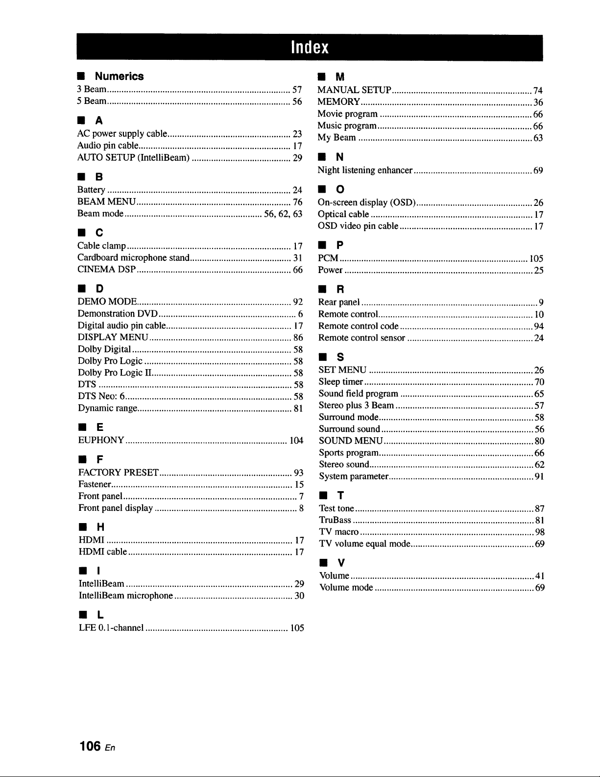
• Numerics
3 Beam ............................................................................ 57
5 Beam ............................................................................ 56
• A
AC power supply cable ................................................... 23
Audio pin cable ............................................................... 17
AUTO SETUP (IntelliBeam) ......................................... 29
• B
Battery ............................................................................ 24
BEAM MENU ................................................................ 76
Beam mode ......................................................... 56, 62, 63
• C
Cable clamp .................................................................... 17
Cardboard microphone stand .......................................... 31
CINEMA DSP ................................................................ 66
• D
DEMO MODE ................................................................ 92
Demonstration DVD ......................................................... 6
Digital audio pin cable .................................................... 17
DISPLAY MENU ........................................................... 86
Dolby Digital .................................................................. 58
Dolby Pro Logic ............................................................. 58
Dolby Pro Logic II.......................................................... 58
DTS ................................................................................ 58
DTS Neo: 6..................................................................... 58
Dynamic range ................................................................ 81
• E
EUPHONY ................................................................... 104
• F
FACTORY PRESET ....................................................... 93
Fastener ........................................................................... 15
Front panel ........................................................................ 7
Front panel display ........................................................... 8
• H
HDMI ............................................................................. 17
HDMI cable .................................................................... 17
• I
IntelliBeam ..................................................................... 29
IntelliBeam microphone ................................................. 30
• L
LFE 0. l-channel ........................................................... 105
• M
MANUAL SETUP .......................................................... 74
MEMORY ....................................................................... 36
Movie program ............................................................... 66
Music program ................................................................ 66
My Beam ........................................................................ 63
• N
Night listening enhancer ................................................. 69
• O
On-screen display (OSD) ................................................ 26
Optical cable ................................................................... 17
OSD video pin cable ....................................................... 17
• P
PCM .............................................................................. 105
Power .............................................................................. 25
• R
Rear panel ......................................................................... 9
Remote control ................................................................ 10
Remote control code ....................................................... 94
Remote control sensor .................................................... 24
• S
SET MENU .................................................................... 26
Sleep timer ...................................................................... 70
Sound field program ....................................................... 65
Stereo plus 3 Beam ......................................................... 57
Surround mode ................................................................ 58
Surround sound ............................................................... 56
SOUND MENU .............................................................. 80
Sports program ................................................................ 66
Stereo sound .................................................................... 62
System parameter ............................................................ 91
• T
Test tone .......................................................................... 87
TruBass ........................................................................... 81
TV macro ........................................................................ 98
TV volume equal mode ................................................... 69
• V
Volume ............................................................................ 41
Volume mode .................................................................. 69
106 En
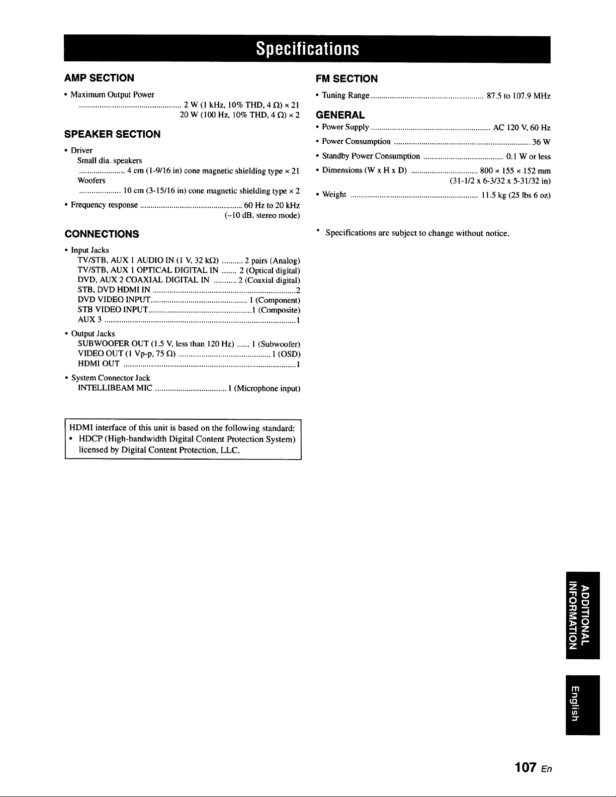
AMP SECTION
• Maximum Output Power
................................................. 2 W (1 kHz, 10% THD, 4 _) x 21
20 W (100 Hz, 10% THD, 4 f2) x 2
SPEAKER SECTION
• Driver
Small dia. speakers
...................... 4 cm (I-9/16 in) cone magnetic shielding type x 21
Woofers
.................... 10 cm (3-15/16 in) cone magnetic shielding type x 2
• Frequency response ................................................. 60 Hz to 20 kHz
(-10 dB, stereo mode)
CONNECTIONS
• Input Jacks
TV/STB, AUX 1 AUDIO IN (1 V, 32 k_) .......... 2 pairs (Analog)
TV/STB, AUX 1 OPTICAL DIGITAL IN ....... 2 (Optical digital)
DVD, AUX 2 COAXIAL DIGITAL IN ........... 2 (Coaxial digital)
STB, DVD HDMI IN .................................................................... 2
DVD VIDEO INPUT .............................................. I (Component)
STB VIDEO INPUT ................................................. 1 (Composite)
AUX 3 ........................................................................................... 1
• Output Jacks
SUBWOOFER OUT (1.5 V, less than 120 Hz) ...... 1 (Subwoofer)
VIDEO OUT (1 Vp-p, 75 12) ............................................ 1 (OSD)
HDMI OUT .................................................................................. 1
• System Connector Jack
INTELLIBEAM MIC .................................. 1 (Microphone input)
FM SECTION
• Tuning Range ...................................................... 87.5 to 107.9 MHz
GENERAL
• Power Supply ......................................................... AC 120 V, 60 Hz
• Power Consumption ................................................................. 36 W
• Standby Power Consumption ...................................... 0.1 W or less
• Dimensions (W x H x D) ................................ 800 x 155 x 152 mm
(31-1/2 x 6-3/32 x 5-31/32 in)
• Weight ............................................................. l 1.5 kg (25 lbs 6 oz)
* Specifications are subject to change without notice.
I
HDMI interface of this unit is based on the following standard: I
• HDCP (High-bandwidth Digital Content Protection System)
licensed by Digital Content Protection, LLC.
107 En
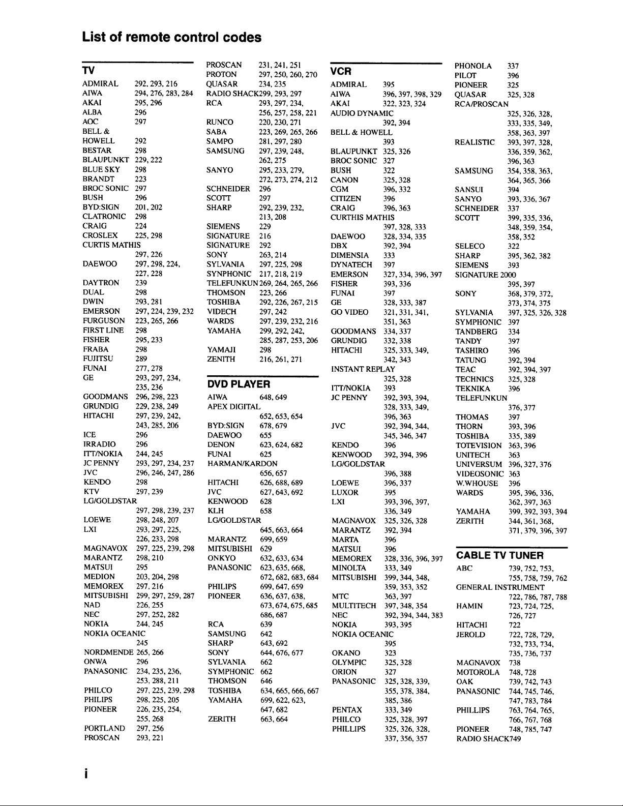
List of remote control codes
TV
ADMIRAL 292. 293, 216
AIWA 294, 276, 283, 284
AKAI 295,296
ALBA 296
AOC 297
BELL &
HOWELL 292
BESTAR 298
BLAUPUNKT 229, 222
BLUE SKY 298
BRANDT 223
BROC SONIC 297
BUSH 296
BYD:SIGN 201. 202
CLATRONIC 298
CRAIG 224
CROSLEX 225,298
CURTIS MATHIS
297, 226
DAEWOO 297,298, 224,
227, 228
DAYTRON 239
DUAL 298
DWIN 293, 281
EMERSON 297, 224, 239, 232
FURGUSON 223,265, 266
FIRST LINE 298
FISHER 295,233
FRABA 298
FUJITSU 289
FUNAI 277,278
GE 293,297, 234,
235,236
GOODMANS 296, 298, 223
GRUNDIG 229, 238, 249
HITACHI 297,239, 242,
243,285, 206
ICE 296
IRRADIO 296
ITT/NOKIA 244, 245
JC PENNY 293, 297, 234, 237
JVC 296,246, 247,286
KENDO 298
KTV 297,239
LG/GOLDSTAR
297.298.239. 237
LOEWE 298,248,207
LXI 293,297,225.
226, 233.298
MAGNAVOX 297, 225.239. 298
M ARAN_Z 298, 210
MATSUI 295
MEDION 203,204, 298
MEMOREX 297,216
MITSUBISHI 299. 297. 259. 287
NAD 226, 255
NEC 297.252. 282
NOKIA 244, 245
NOKIA OCEANIC
245
NORDMENDE 265, 266
ONWA
PANASONIC
PHILCO
PHILIPS
PIONEER
PORTLAND
PROSCAN
296
234, 235,236,
253,288,211
297,225,239, 298
298,225, 205
226,235,254,
255,268
297,256
293,221
PROSCAN 231,241,251
PROTON 297, 250, 260, 270
QUASAR 234, 235
RADIO SHACK299, 293, 297
RCA 293, 297, 234,
256, 257,258,221
RUNCO 220, 230, 271
SABA 223, 269, 265, 266
SAMPO 281,297,280
SAMSUNG 297. 239, 248,
262, 275
SANYO 295, 233, 279,
272, 273,274, 212
SCHNEIDER 296
SCOTT 297
SHARP 292, 239, 232,
213, 208
SIEMENS 229
SIGNATURE 216
SIGNATURE 292
SONY 263, 214
SYLVANIA 297, 225, 298
SYNPHONIC 217,218,219
TELEFUNKUN 269, 264, 265. 266
THOMSON 223, 266
TOSHIBA 292, 226, 267, 215
VIDECH 297, 242
WARDS 297, 239, 232, 216
YAMAHA 299, 292, 242,
285, 287, 253,206
YAMAJI 298
ZENITH 216, 261, 27 l
DVD PLAYER
AIWA 648. 649
APEX DIGITAL
652, 653, 654
BYD:SIGN 678, 679
DAEWOO 655
DENON 623, 624, 682
FUNAI 625
HARMAN/KARDON
656, 657
HITACHI 626, 688, 689
JVC 627, 643, 692
KENWOOD 628
KLH 658
LG/GOLDSTAR
645. 663,664
MARANTZ 699, 659
MITSUBISHI 629
ONKYO 632, 633, 634
PANASONIC 623,635, 668,
672, 682, 683,684
PHILIPS 699, 647,659
PIONEER 636, 637, 638,
673,674, 675,685
686, 687
RCA 639
SAMSUNG 642
SHARP 643, 692
SONY 644, 676, 677
SYLVANIA 662
SYMPHONIC 662
THOMSON 646
TOSHIBA 634, 665, 666, 667
YAMAHA 699, 622, 623,
647, 682
ZERITH 663,664
PHONOLA 337
VCR PILOT 396
ADMIRAL 395 PIONEER 325
AIWA 396, 397, 398, 329 QUASAR 325,328
AKAI 322. 323. 324 RCA/PROSCAN
AUDIO DYNAMIC 325,326, 328,
392, 394 333,335. 349,
BELL & HOWELL 358,363, 397
393 REALISTIC 393, 397,328,
BLAUPUNKT 325, 326 336, 359, 362,
BROC SONIC 327 396. 363
BUSH 322 SAMSUNG 354, 358.363,
CANON 325,328 364, 365.366
CGM 396, 332 SANSUI 394
CITIZEN 396 SANYO 393,336. 367
CRAIG 396, 363 SCHNEIDER 337
CURTHIS MATHIS SCOTT 399, 335,336,
397, 328, 333 348.359, 354.
DAEWOO 328. 334, 335 358. 352
DBX 392, 394 SELECO 322
D1MENS1A 333 SHARP 395. 362, 382
DYNATECH 397 SIEMENS 393
EMERSON 327,334, 396, 397 SIGNATURE 2000
FISHER 393,336 395,397
FUNAI 397
GE 328, 333, 387
GO VIDEO 321,331,341,
35t, 363
GOODMANS 334. 337
GRUNDIG 332. 338
HITACHI 325, 333. 349,
342, 343
INSTANT REPLAY
325, 328
ITr/NOKIA 393
JC PENNY 392,393,394,
328,333,349,
396,363
JVC 392,394,344,
345,346,347
KENDO 396
KENWOOD 392,394,396
LG/GOLDSTAR
396,388
LOEWE
LUXOR
LXI
MAGNAVOX
MARANTZ
MARTA
MATSUI
MEMOREX
MINOLTA
MITSUBISHI
MTC
MULTITECH
NEC
NOKIA
396,337
395
393,396,397,
336,349
325,326,328
392,394
396
396
328,336,396,397
333,349
399,344, 348,
359,353,352
363,397
397,348,354
392,394,344,383
393,395
NOKIA OCEANIC
395
OKANO
OLYMPIC
ORLON
PANASONIC
PENTAX
PHILCO
PHILLIPS
323
325,328
327
325,328,339,
355. 378, 384,
385,386
333,349
325,328, 397
325,326,328.
337.356,357
SONY 368, 379, 372,
373,374, 375
SYLVANIA 397, 325, 326. 328
SYMPHONIC 397
TANDBERG 334
TANDY 397
TASHIRO 396
TATUNG 392, 394
TEAC 392, 394, 397
TECHNICS 325, 328
TEKNIKA 396
TELEFUNKUN
376,377
THOMAS 397
THORN 393. 396
TOSHIBA 335,389
TOTEVISION 363, 396
UNITECH 363
UNIVERSUM 396, 327,376
V1DEOSONIC 363
W.WHOUSE 396
WARDS 395, 396, 336,
362, 397,363
YAMAHA 399, 392, 393,394
ZERITH 344, 361,368,
371,379, 396, 397
CABLE TV TUNER
ABC 739. 752. 753.
755. 758, 759, 762
GENERAL INSTRUMENT
722,786, 787, 788
HAMIN 723. 724, 725,
726,727
HITACHI 722
JEROLD 722, 728, 729,
732.733, 734.
735,736, 737
MAGNAVOX 738
MOTOROLA 748,728
OAK 739. 742, 743
PANASONIC 744, 745,746,
747. 783. 784
PHILLIPS 763. 764, 765,
766. 767, 768
PIONEER 748, 785,747
RADIO SHACK749
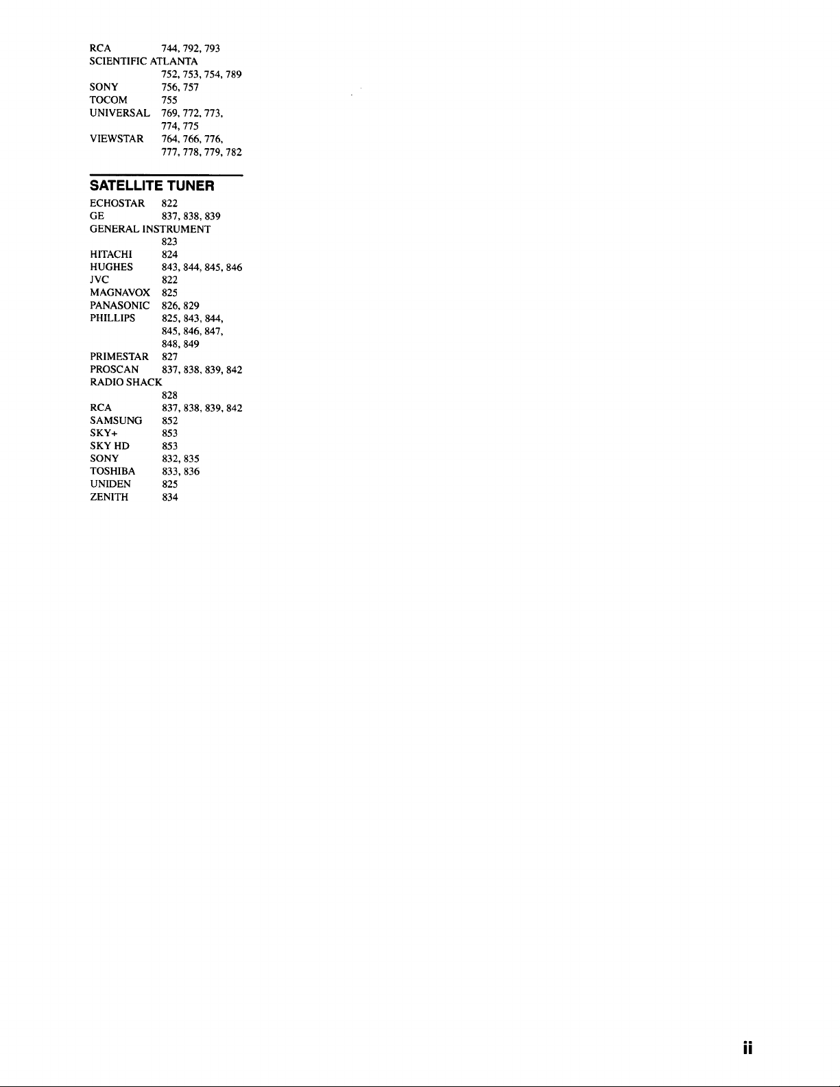
RCA 744, 792, 793
SCIENTIFIC ATLANTA
752, 753,754, 789
SONY 756, 757
TOCOM 755
UNIVERSAL 769, 772, 773,
774, 775
VIEWSTAR 764, 766, 776,
777, 778, 779, 782
SATELLITE TUNER
ECHOSTAR 822
GE 837,838, 839
GENERAL INSTRUMENT
823
HITACHI
HUGHES
JVC
MAGNAVOX
PANASONIC
PHILLIPS
PRIMESTAR
PROSCAN
824
843,844,845,846
822
825
826,829
825,843,844
845,846,847,
848,849
827
837,838,839,842
RADIO SHACK
828
RCA
SAMSUNG
SKY+
SKY HD
SONY
TOSHIBA
UNIDEN
ZENITH
837,838,839,842
852
853
853
832,835
833,836
825
834
ii

OYAMAHA
© 2008 YAMAHA CORPORATION All rights reserved.
YAMAHA ELECTRONICS CORPORATION, USA 6660 ORANGETHORPE AVE., BUENA PARK, CALIF. 90620, U.S.A.
YAMAHA CANADA MUSIC LTD. 135 MILNER AVE., SCARBOROUGH, ONTARIO M1S 3R1, CANADA
YAMAHA ELECTRONIK EUROPA G.m.b.N. SIEMENSSTR. 22-34, 25462 RELLINGEN BEI HAMBURG, GERMANY
YAMAHA ELECTRONIQUE FRANCE S.A. RUE AMBROtSE CROIZAT BP70 CROISSY-BEAUBOURG 77312 MARNE-LA-VALLEE CEDEX02, FRANCE
YAMAHA ELECTRONICS (UK) LTD. YAMAHA HOUSE, 200 RICKMANSWORTH ROAD WATFORD, HERTS WD18 7GQ, ENGLAND
YAMAHA SCANDINAVIA A.B. J A WETTERGRENS GATA f, BOX 30053, 400 43 VASTRA FR_LUNDA, SWEDEN
YAMAHA MUSIC AUSTRALIA PTY. LTD. LEVEL 1, 99 QUEENSBRIDGE STREET, SOUTHBANK, VIC 3006, AUSTRALIA
YAMAHA COP_ORATION
Printed in Malaysia c WK75600
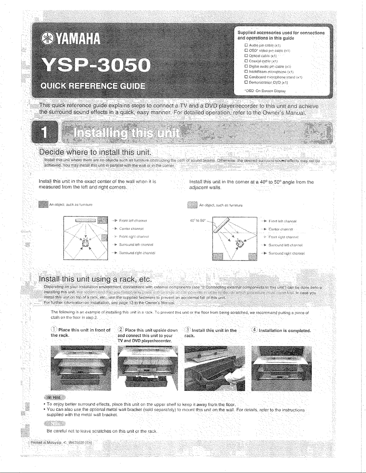
_,qst£t]i thi_ u_sJl in if}6 COmei' at a 40 a to 50 _' ari_Ie ,_ror_ _t_e
adjacem wa_s
4(P_¢_ !'0' ....,_ ._#Q.
i oy
LI P]aoe this _nit in front of i 2 Place finis unil upside down 3 _nStati, ihi_ un__ in the
the rack. an_1connect _flis unit_o your rack.
T_ and DVD player/re_ord_r,
i141.: :Instal[alien is completed.
iZi
- To elliOy be!le!" s[;rt'ouna ei_eo_,s, place _his dn_[ or_ _'_e uppe[ sheff k:_ k{_eD _ away _rom the t!oor.
• You can aiso use ',he op_'.oa__tmetal w_._ti br_ckei (sold sepan_taly_, to moun_ _'.,is UFiit On the wail For delai_s rr_]_r to the ins_roctio_s
s_ppf_eg w_lh the rr, ela_ wall braoket
Be careh_ noI[o _eave scra;cl_es on [his uni_ er Erierack
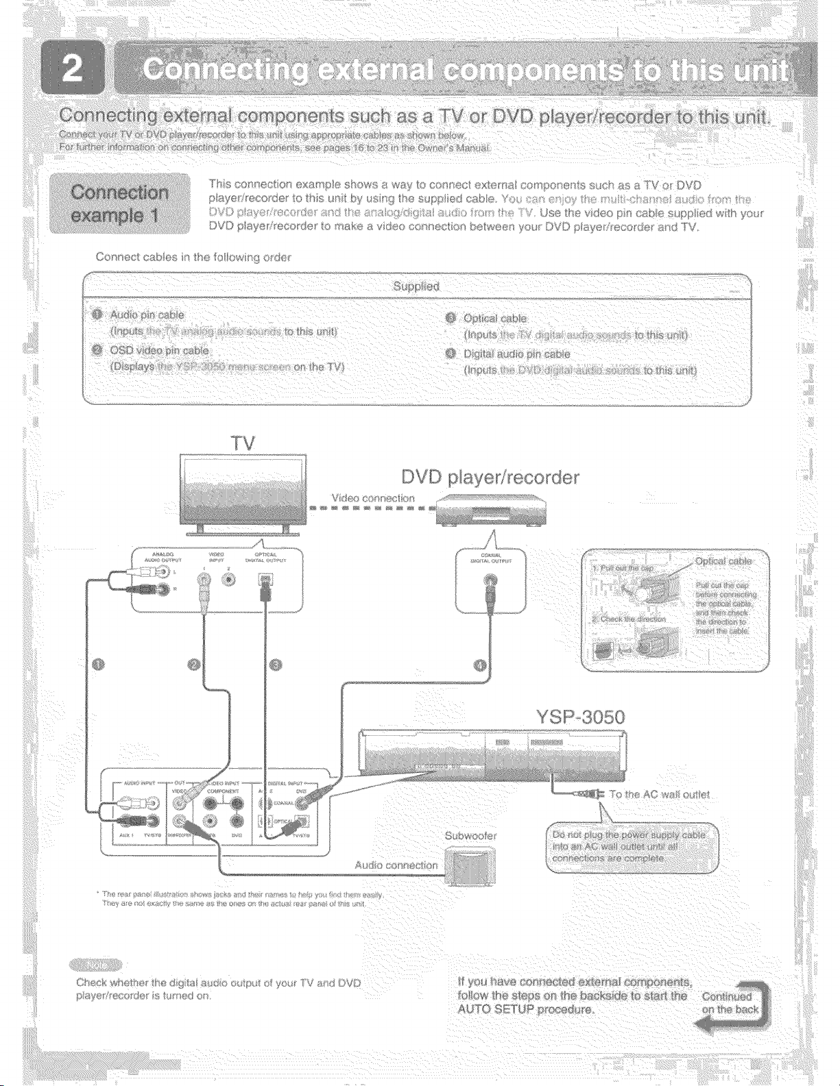
_ ...."' _'""%'_!;!i'iii'I¸ !_ } }/i i!¸I¸¸i'i¸¸}/ } ! !}/ ((( }( { } /_' !(iii(:}:_!ii!i i
iiiiii
CO' tect cab®s n _'_e to ow _9 o/cSe
('; _;@ ed
DVD p aye_i_eco_de_
i
ff !'
ii!;_ii!ii!ii_i
/ i iI
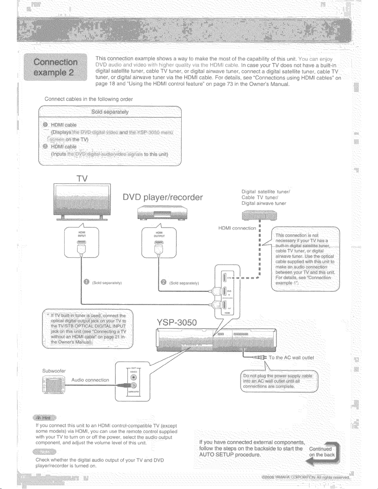
)VD p:a/ed_eco_de
/¢'4 WIR _*7t
_H 4s
_>:'\,','s:{::_:>:_ :(;A:,:x(_;_:4.:_'_:.tY:
_,;, #
f
} ©F£
.,, H_
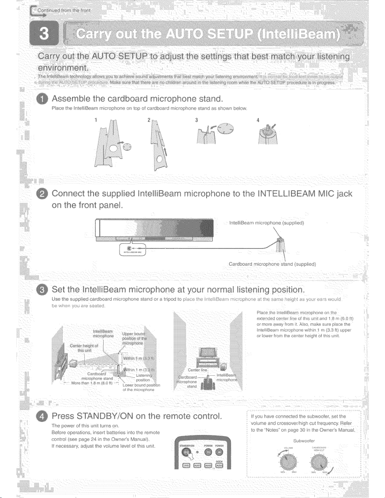
t_;__ } ou_ u e AU SCTUP t
Assemble _ne cardboard micro snone 5 ana
R
Y
Connect _ne
[ne _ron_[ ar_e
nteHiBeam rT_Ict_ophon@[8 _ne NT£LLIBEAM Ml( 8cK
_ Sel _me Intell Be_ r_ mKsrc }none _:_you r_o_"_'_na_t_st(_n_ng poslh(
}
_:,_ ........
3TANDBY'ON
remote con_ro_.
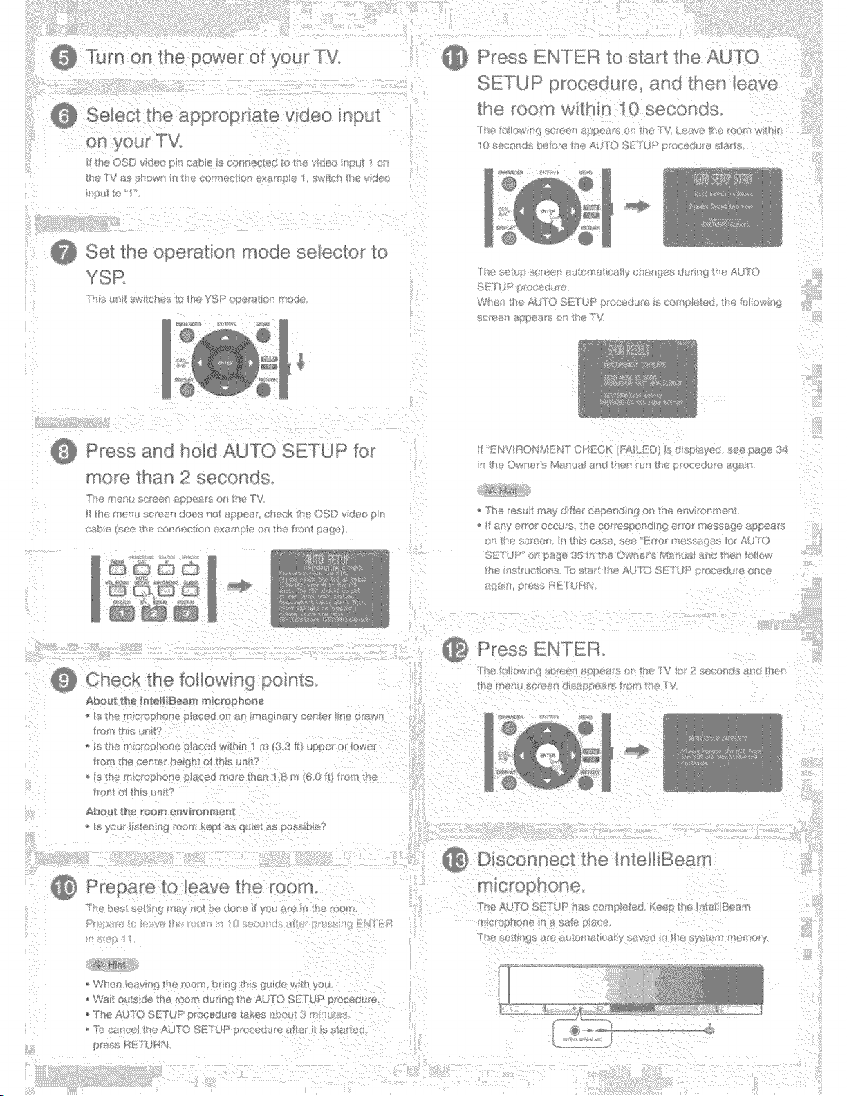
%
] foceGu t_@
}6 _@CO@GS
?%
Press _:s__ _ :d AUTO SE:]'2
Checb me _oI!owing _so__s
(£1£_ L£" ;ll
P_ess t-,:H _ L}4
sv,/_ 2
Pre_ _re TO cave _ne
_'""T s o .... @__s>(%,.}Y}R@ [ U']@ _f'/[@h/£'gsS_r
°'x{sH} [}_I(}_X
k
AL/°_O ST !I,]R _'
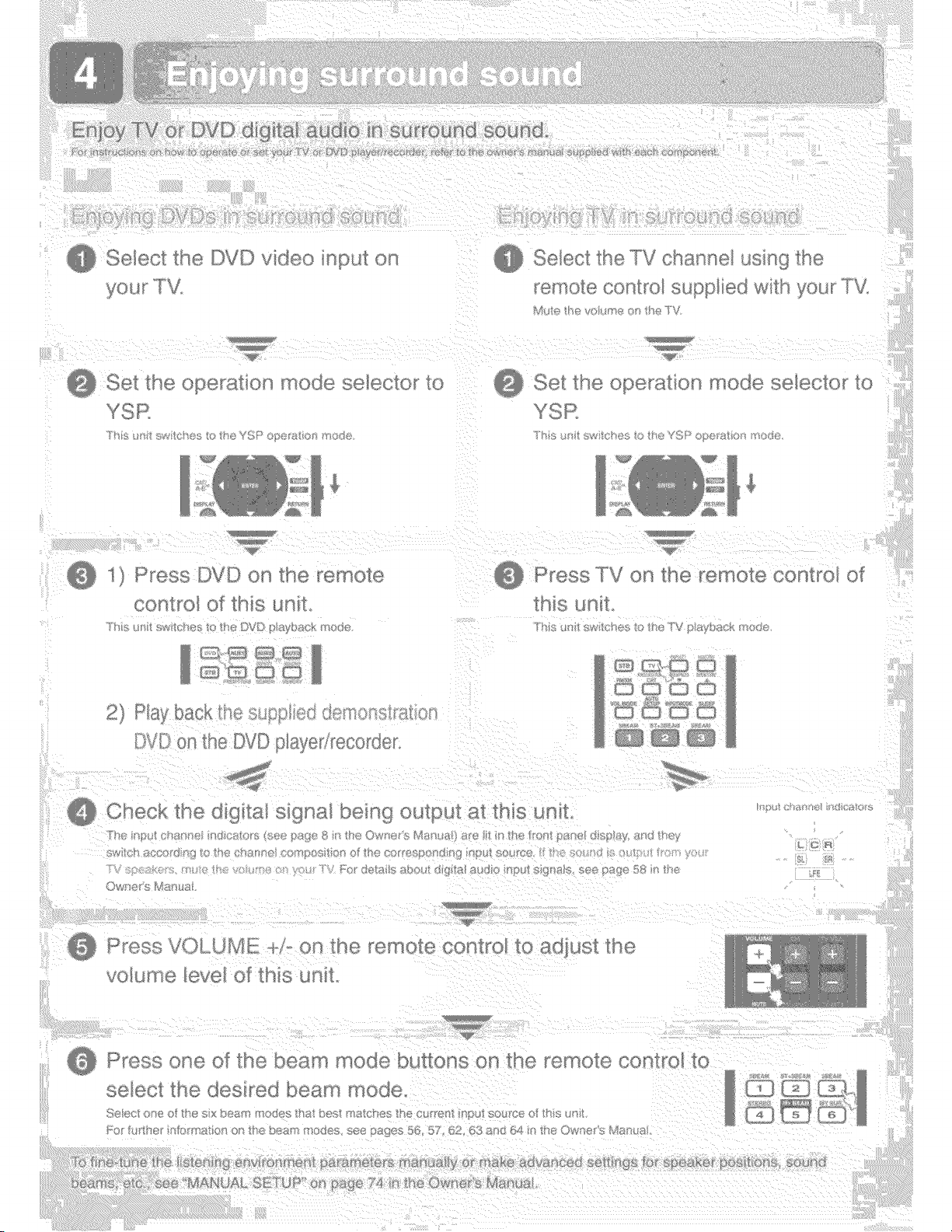
Se/ecl !.he
3 M_) L.M
s
b@ ....... ©[8{I0 iuo_,.s S@I@C{C I[
............ [_'VD
Y F_t2
Y}l{,
J_
f_e I.JVL OlaS0 [@co[@e[
i_41'II(911=I (X}FIIIU {}T
;:sl t_i I'_I@
,lINe eve/(I)Y _{HIS _ I_II
'Wll ©@IF]€
}W_ H;_ is J'_+_aNs5
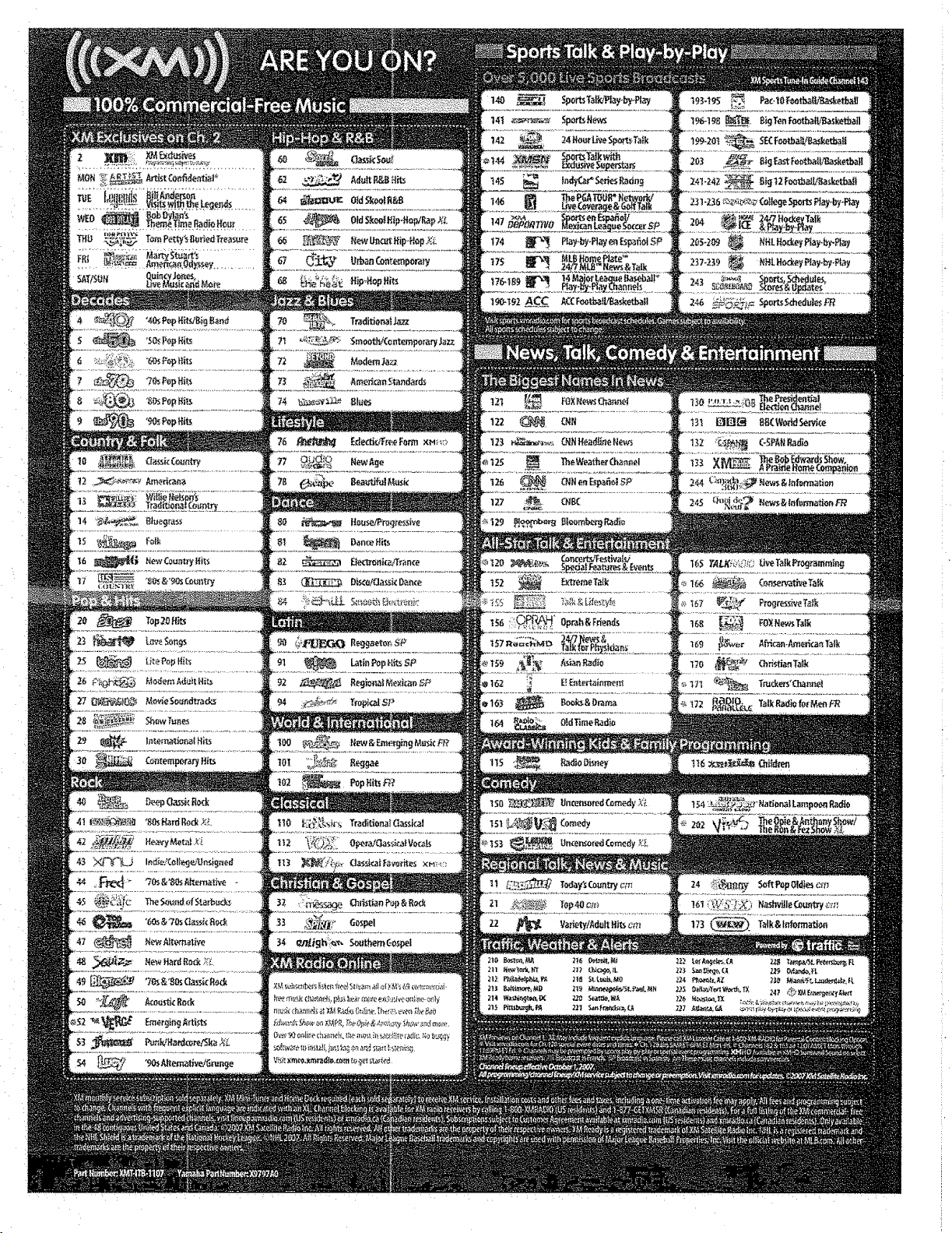

EXCLUSIVES YOU'LL ONLY HEAR ON XM


YAMAHA Home Audio products are designed and manufactured to provide a high level of trouble-free performance. YAMAHA Electronics Corporation, USA, is
proud of the experienced craftsmanship that goes into each and every YAMAHA Home Audio product. YAMAHA sells its Home Audio products only through a network
of high quality, specially authorized dealers and is pleased to offer the following Limited Warranty, which applies only to products purchased from our authorized dealers.
YAMAHA Home Audio products are backed by a nationwide network of high quality YAMAHA Authorized Service Centers, providing prompt, courteous, and
professional service. We suggest that you read the Limited Warranty thoroughly, and invite you to contact your authorized YAMAHA dealer or the YAMAHA Electronics
Corporation, USA, Service Department if you have any questions.
OYAMAHA
L J[ D WARRANTY
HOME AUDIO PRODUCTS
Type of Product Duration of Warranty
(beginning from first consumer purchase)
A/V and Stereo Receivers, Processor and Integrated Amplifiers, Separate Am-
plifiers and Preamplifiers, Tuners, CD Players and Changers, HDD Players and
Recorders, Powered Loudspeakers and Speaker Systems purchased individu-
ally, as a pair, or as part of an Integrated or Packaged system .................................................................................... 2 years
Cassette Decks, DVD Players and Changers, Integrated Systems (Receiver or
Amplifier combined or on same chassis with CD or DVD Player), Multimedia
Speakers and Accessories ............................................................................................................................................. 1 year
What is Covered and what is Not Covered:
This warranty covers all defects in materials or workmanship in this product, but DOES NOT COVER the following:
(1) Damage, deterioration or malfunction resulting from:
a. Accident, negligence, misuse, abuse, improper installation or operation or failure to follow instructions contained in your Owner's Manual.
h. Any shipment of the product. (Claims must be presented to the carrier.)
c. Repair or attempted repair by anyone other than YAMAHA or an authorized YAMAHA Service Center.
(2) Any unit which has been altered or on which the serial number has been defaced, modified or removed.
(3) Normal wear, battery replacement and any periodic maintenance.
(4) Any unit which has not been purchased from an authorized YAMAHA Home Audio dealer in the USA. If you are uncertain as to whether a
dealer has been authorized by YAMAHA, please contact YAMAHA's Service Department.
(5) Any unit used for industrial or commercial purposes.
Who may enforce the warranty:
This warranty is enforceable only by the original purchaser.
What we will pay for and what you must pay for:
YAMAHA will repair or replace units covered by this warranty, without charge to the consumer for labor or materials. Some repair parts may be
used or rebuilt replacements, that meet or exceed Yamaha specifications for new parts, in exchange for defective parts. YOU ARE RESPONSIBLE FOR
ANY INSTALLATION OR REMOVAL CHARGES AND FOR ANY INITIAL SHIPPING CHARGES, if the product(s) must be shipped for warranty
service. However, we will pay the return shipping charges to any destination within the USA if the repairs are covered by the warranty.
How you can get Warranty Service:
(I) If your YAMAHA product(s) require service, contact the authorized YAMAHA dealer and the dealer will advise you of the procedures to be
followed. If this is not practical, contact YAMAHA at the address, telephone number or Internet URL shown below. We may request that you
send the defective product(s) to a local authorized YAMAHA Service Center, to an authorized YAMAHA Regional Service Center, or
authorize return of the defective product(s) to YAMAHA for repair.
(2) Product(s) shipped for service should be packed securely and must be accompanied by a detailed explanation of the problem(s) requiring
service, as well as your sales receipt or other proof of date and place of purchase, as evidence of warranty coverage.
(3) Warranty registration is not required for warranty coverage.
Limitation of Implied Warranties:
ANY IMPLIED WARRANTIES, INCLUDING WARRANTIES OF MERCHANTABILITY AND FITNESS FOR A PARTICULAR PURPOSE,
ARE LIMITED IN DURATION TO THE LENGTH OF THIS WARRANTY. SOME STATES DO NOT ALLOW LIMITATIONS ON HOW LONG AN
IMPLIED WARRANTY LASTS, SO THE ABOVE LIMITATION MAY NOT APPLY TO YOU.
Exclusion of Damages:
YAMAHA'S LIABILITY FOR ANY DEFECTIVE PRODUCI" IS LIMITED TO REPAIR OR REPLACEMENT OF THE PRODUCT, AT OUR
OPTION. IF WE ELECT TO REPLACE THE PRODUCT, THE REPLACEMENT MAY BE A RECONDITIONED UNIT. YAMAHA SHALL NOT BE
LIABLE FOR DAMAGES BASED UPON INCONVENIENCE, LOSS OF USE, DAMAGE TO ANY OTHER EQUIPMENT OR OTHER ITEMS AT
THE SITE OF USE, OR ANY OTHER DAMAGES WHETHER INCIDENTAL, CONSEQUENTIAL OR OTtIERWISE. SOME STATES DO NOT
ALLOW LIMITATIONS ON HOW LONG AN IMPLIED WARRANTY LASTS AND/OR DO NOT ALLOW THE EXCLUSION OR LIMITATION OF
INCIDENTAL OR CONSEQUENTIAL DAMAGES, SO THE ABOVE LIMITATIONS AND EXCLUSIONS MAY NOT APPLY TO YOU. THIS
WARRANTY GIVES YOU SPECIFIC LEGAL RIGHTS, AND YOU MAY ALSO HAVE OTHER RIGHTS WHICH VARY FROM STATE TO STATE.
Should you have any questions about service received or if you need assistance in locating an authorized YAMAHA Service Center, please contact:
OYAMAHA
SERVICE DEPARTMENT
YAMAHA Electronics Corporation, USA
6660 Orangethorpe Avenue, Buena Park, California 90620-1345
Telephone: (714) 522-9105 Internet URL: http://www.yamaha.com/yeci
Do not return any product to the above address; it is not a service location. YAMAHA products are backed by a nationwide network of high quality
YAMAHA authorized Service Centers, providing prompt, courteous and professional service. For referral to your nearest authorized YAMAHA
Preferred Customer Service Center or authorized YAMAHA Regional Service Center call 1-800-4 YAMAHA.
WM18180