Cayman GT4
Owner’s Manual
WKD 981 08 21 16 Cayman GT4
Dr. Ing. h.c. F. Porsche AG is the owner of
numerous trademarks, both registered and
unregistered, including without limitation the
Porsche Crest
®
, Porsche
®
, Boxster
®
, Carrera
®
,
Cayenne
®
, Cayman
®
, Panamera
®
, Macan
®
,
Speedster
®
, Tiptronic
®
, Tequipment
®
,
VarioCam
®
, PCM™, PDK
®
, 911™, 4S
®
, RS
®
and
the model numbers and the distinctive shapes of
the Porsche automobiles such as, the federally
registered 911 and Boxster automobiles in the
US. The third party trademarks contained herein
are the properties of their respective owners.
Porsche Cars North America, Inc. and its affiliates
believes the specifications to be correct at the
time of printing. However, specifications, standard
equipment and options are subject to change
without notice. Some options may be unavailable
when a car is built. Some vehicles may be shown
with equipment that is not available in the US and
Canada. Please ask your authorized dealer for
advice concerning the current availability of
options and verify the optional equipment that you
ordered.
Porsche recommends safety belt usage and
observance of traffic laws at all times.
© 2014 Dr. Ing. h.c. F. Porsche AG
Orientation guides in the Owner’s Manual
The orientation guides in the Owner’s Manual are
highlighted in yellow.
Overall Table of Contents
At the start of the Owner’s Manual you will find an
overview of the overall contents of the Owner’s
Manual.
Section Contents
There is a summary of topics with the
corresponding page numbers at the beginning of
each main chapter.
Index
There is a detailed, alphabetical index at the end
of this Owner’s Manual.
Safety instructions in the Owner’s Manual
For your own protection and longer service life of
your car, please heed all operating instructions
and special warnings. These special warnings
contain important messages regarding your
safety and/or the potential for damage to your
Porsche. Ignoring them could result in serious
mechanical failure, serious personal injury or
death.
Various types of safety instructions are used in
this Owner’s Manual.
Failure to observe safety instructions in the
“Danger” category will result in serious injury or
death.
Failure to observe safety instructions in the
“Warning” category could result in serious injury
or death.
Failure to observe safety instructions in the
“Caution” category can result in moderate or
minor injury.
Possible vehicle damage
Failure to observe safety instructions in the
“Notice” category could result in damage to the
vehicle.
Information
Additional information, tips and instructions are
indicated by the word “Information”. Please read
this information carefully and follow the
instructions.
WKD 981 08 21 16 03/15
Serious injury or death
Possible serious injury
or death
Possible moderate or
minor injury
DANGER
h
WARNING
h
CAUTION
h
NOTICE

1
Dear Owner,
Thank you for choosing a Porsche sports car. No
other car embodies such a unique blend of
legendary heritage and cutting edge innovation.
For maximum safety and pleasure, we encourage
you to read the Owner's Manual and take time to
familiarize yourself with the operation of your
Porsche vehicle before you drive it. Always drive
within your own unique capabilities as a driver and
ensure that anyone else driving your Porsche
vehicle does the same. To help prevent or
minimize injury, always use your safety belts and
always lawfully operate your Porsche vehicle.
Always keep your Owner's Manual in the car. If you
sell your Porsche vehicle, pass the Owner's
Manual and other operation manuals on to the new
owner.
Should you have any questions regarding the
operation or maintenance of your vehicle, please
call 1-800-PORSCHE or contact your authorized
Porsche dealership.
A separate Maintenance Booklet explains how
you can keep your Porsche in top driving condition
by having it serviced regularly.
A separate Warranty and Customer
Information Booklet contains detailed
information about the warranties covering your
Porsche.
For U.S. only:
If you believe that your vehicle has a fault which
could cause a crash, injury or death, you should
immediately inform the National Highway Traffic
Safety Administration (NHTSA) in addition to
notifying Porsche Cars North America, Inc.
(Porsche Cars N.A.).
If NHTSA receives similar complaints, it may open
an investigation, and if it finds that a safety
problem exists in a group of vehicles, it may order
a recall and remedy campaign. However, NHTSA
cannot become involved in individual problems
between you and your dealer, or Porsche Cars
N.A..
To contact NHTSA, you may call the Vehicle Safety
Hotline toll-free at
1–888–327–4236 (TTY: 1–800–424–9153);
go to
http://www.safercar.gov;
or write to:
Administrator, NHTSA, 1200 New Jersey Ave, SE,
Washington, DC 20590.
You can also obtain other information about motor
vehicle safety from http://www.safercar.gov.
Your car has thousands of parts and components
which have been designed and manufactured in
accordance with Porsche’s high standards of
engineering quality and safety.
Any alteration of the vehicle may negate or
interfere with those safety features built into the
vehicle. Modifications may be carried out on your
vehicle only if approved by Porsche.
Your Porsche is intended to be used in a safe
manner obeying the local traffic laws and in the
light of driving conditions faced by you, and in
accordance with the instructions provided in this
Owner’s Manual.
f Do not misuse your Porsche by ignoring those
laws and driving conditions, or by ignoring the
instructions in this manual.
f Do not alter your Porsche. Any alteration could
create dangerous conditions or defeat safety
engineering features built into your car.
Risk of damage to the engine due to inadequate
supply of oil.
The fitting of racing tires (e.g. slicks) for sporting
events is not approved by Porsche. Very high
cornering speeds can be achieved with racing
tires. However, the resulting transverse
acceleration values would jeopardize the
adequate supply of oil to the engine. Porsche
therefore will not accept any warranty or accept
any liability for damage occurring as a result of
non-compliance with this provision.
f Do not fit racing tires (e.g. slicks) for sporting
events on your vehicle.
Alteration or misuse of
vehicle
WARNING
h
NOTICE

2
Regularly check your vehicle for signs of
damage.
Damaged or missing aer
odynamic
components such as spoilers or underside
panels affect the driving behavior and
therefore must be replaced immediately.
Your car may have all or some of the components
described in this manual.
Should you have difficulty understanding any of
the explanations of features or equipment installed
in your vehicle, contact your authorized Porsche
dealer. He/She will be glad to assist you. Also
check with your dealer on other available options
or equipment.
Throughout this booklet, left is designated as the
driver's side of the vehicle, and right as the
passenger's side of the vehicle.
Text, illustrations and specifications in this manual
are based on the information available at the time
of printing.
It has always been Porsche’s policy to
continuously improve its products. Porsche,
therefore, reserves the right to make changes in
design and specification, and to make additions or
improvements in its product without incurring any
obligation to install them on products previously
manufactured.
We wish you many miles of safe and pleasurable
driving in your Porsche.
Note to owners
In Canada, this manual is also available in French.
To obtain a copy contact your dealer or write to:
Note aux proprietaires
Au Canada on peut se procurer un exemplaire de
ce Manuel en français auprès du concessionaire
ou du:
Porsche Cars Canada, Ltd.
Automobiles Porsche Canada, LTEE
5925 Airport Road
Suite 420
Mississauga, Ontario
Canada, L4V 1W1
Telephone number for customer assistance:
1-800-PORSCHE / Option 3
Development Philosophy
Porsche Cayman GT4 stands for a sports car with
exceptional performance, both on the road and on
the race circuit. This objective means that, in the
event of any compromise being required between
sportiness and comfort during the development
process, the tendency will be geared more
towards sportiness. This can result in the following
restrictions in comfort:
– Brake squeal when light pressure applied to
the pedal shortly before stopping.
– Cracking noise in area of front-axle coil
springs.
– Aerodynamic-related extremely low vehicle
position with restrictions in terms of ground
clearance.

3
Sport tires
Your vehicle is equipped with special sport tires
(ultra high performance tires). This type of tire is
approved for use on public highways and comply
with all statutory requirements and safety criteria.
The design of the tire is also geared towards use
on racing circuits (driver safety training courses,
sports driving schools, Club Sport events) and
provides distinct advantages here in terms of dry
grip and wear compared to conventional road
tires.
The major features are a reduced tread depth and
a special tread pattern and carcass.
The design features of this sports tire result
in the following effects compared with other
summer tires when used under normal
driving conditions:
– Sport tires have a smaller tread depth, and
thus can reach their wear limit sooner.
As with all tires, the attainable mileage
depends on the individual driving style and the
conditions of use.
– Exercise caution when driving on wet roads,
paying special attention to hydroplaning
situations (stagnant water, puddles, lane
grooves). Sport tires have a lower tread depth
than normal tires and you must therefore adapt
speed accordingly when driving on wet
surfaces.
– The driver’s skill level must be commensurate
with the vehicle performance levels in the
upper range limits, due to increased safety
risks in the upper range limits.
f Sport tires are not suitable for use in cold,
snowy, or icy conditions. At outside
temperatures below 45 °F (7 °C) change to
snow tires.
f Notify anyone using your car of these
characteristics and possible effects.
The reduced tire tread depth means that there is
an increased risk of aquaplaning on wet roads.
f When driving on wet or mud-covered roads
reduce speed significantly.
Sport tires have a smaller tread depth, and thus
can reach their wear limit sooner.
It is important to check tire wear frequently to
avoid risk of serious personal injury or death from
worn tires.
f Check tire wear frequently.
Driving on Race Circuit
(e.g. sports driving schools, motor
sport events)
Brake fluid, brake pads and brake disks
Brake fluid absorbs moisture from the air over
time. This accumulation of water lowers the
boiling point and can impair braking action if the
brakes are subjected to high temperatures, such
as can occur on race circuits (sports driving
school, motor sport events).
The brake fluid should therefore not be more than
12 months old if the vehicle is driven on race
circuits (sports driving school, motor sport
events).
f For more information, see the “ Maintenance”
booklet.
Wear on the brake pads and brake disks depends
to a great extent on the driving style and driving
conditions. Wear on the brake components is
increased as a result of high temperatures, such
as can occur on race circuits (sports driving
school, motor sport events).
f Before and after driving on race circuits
(sports driving school, motor sport events), it
is important therefore to carry out a visual
inspection of the brake pads and brake disks
for wear.
Racing tires
The fitting of racing tires (e.g. slicks) for sporting
events is not approved by Porsche.
Very high cornering speeds can be achieved with
racing tires. The resulting transverse acceleration
values would jeopardise the adequate supply of oil
to the engine.
Porsche therefore refuses to accept any warranty
or liability for damage occurring as a result of non-
compliance with this provision.
Loss of Road Surface
Contact, Control over
the Vehicle and Braking
Ability
Worn Tires
DANGER
h
DANGER
h

4
Setting and operating vehicle
components when driving
Setting or operating the multi-function display,
radio, navigation system, telephone or other
equipment when driving could distract you from
the traffic. You could lose control of the vehicle
resulting in serious personal injury or death.
f Operate the components while driving only if
the traffic situation allows you to do so safely.
f Carry out any complicated operating or setting
procedures only with the vehicle stationary.
Engine Exhaust
Engine exhaust is dangerous if inhaled.
Engine exhaust fumes have many components
which you can smell. They also contain carbon
monoxide (CO), which is a colorless and odorless
gas.
Carbon monoxide can cause unconsciousness
and even death if inhaled.
f Never start or let the engine run in an en-
closed, unventilated area.
It is not recommended to sit in your car for
prolonged periods with the engine on and the
car not moving.
Engine exhaust, some of its constituents, and
certain vehicle components contain or emit
chemicals known to the State of California to
cause cancer and birth defects or other
reproductive harm.
In addition, certain fluids contained in vehicles and
certain products of component wear contain or
emit chemicals known to the State of California to
cause cancer and birth defects or other
reproductive harm.
Hot Exhaust Pipes
The exhaust pipe is hot when the vehicle is running
and remains hot for some time after the vehicle is
turned off.
f To prevent injury, make a point of noting where
your vehicle’s exhaust pipe is, avoid placing
your legs near the exhaust pipe, and closely
supervise children around the vehicle during
time when the exhaust pipe could be hot.
A hot exhaust pipe can cause serious burns.
Portable Fuel Containers
Portable fuel containers may leak, whether they
are full or partially empty. Fuel leaking from a
portable container carried in your vehicle could, in
case of an accident, cause a fire or explosion.
f Never carry additional fuel in portable
containers in your vehicle.
Ground Clearance
Risk of damage to the vehicle due to lower ground
clearance.
The vehicle may touch the ground as a result of
reduced ground clearance.
f Drive carefully and slowly on steep slopes
(e. g. parking lots, curbs, uneven roads, lifting
platforms etc.).
f Avoid steep ramps.
Porsche Ceramic Composite Brake
(PCCB)
f Please see the chapter “BRAKES”
on page 121.
The high-performance brake system is designed
for optimal braking effect at all speeds and
temperatures.
Certain speeds, braking forces and ambient
conditions (such as temperature and humidity)
therefore might cause brake noises.
Wear on the different components and braking
system, such as brake pads and brake disks,
depends to a great extent on the individual driving
style and the conditions of use and therefore
cannot be expressed in actual miles on the road.
The values communicated by Porsche are based
on normal operation adapted to traffic. Wear
increases considerably when the vehicle is driven
on race tracks or through an aggressive driving
style.
f Please consult an authorized Porsche dealer
about the current guidelines in effect before
such use of your vehicle.
Operating components
while driving
Engine exhaust
inhalation
WARNING
h
DANGER
h
California
Proposition 65
Hot exhaust pipes
Portable fuel container
leaks
WARNING
h
WARNING
h
DANGER
h
NOTICE

5
Service Brake
f Please see the chapter “BRAKES”
on page 120.
Both the standard brake system with composite
brake disks and the Porsche Ceramic Composite
Brake (PCCB) are high-performance brake
systems, designed specifically for driving on race
circuits.
Certain speeds, braking forces and ambient
conditions (such as temperature and humidity)
may therefore cause the brakes to squeal. This
also applies after completion of the running-in
phase required for the new brake components.
Wear on different components of the brake
system, e.g. brake pads or brake disks, depends
to a great extent on the individual driving style and
the conditions of use and therefore cannot be
expressed in actual miles on the road.
The values communicated by Porsche are based
on normal operation adapted to traffic. Wear
increases considerably when the vehicle is driven
on race tracks or as a result of aggressive driving.
Before driving your vehicle in this way, please ask
your authorized Porsche dealer about the
guidelines that currently apply.
Dear Porsche Owner,
A lot has gone into the manufacture of your
Porsche sports car, including advanced
engineering, rigid quality control and demanding
inspections. These engineering and safety
features will be enhanced by you…
the safe driver…
– who knows her/his car and all controls,
– who maintains the vehicle properly,
– who uses driving skills wisely and always
drives within her/his own capabilities and the
level of familiarity with the vehicle.
You will find helpful hints in this manual on how to
perform most of the checks listed on the following
pages. If in doubt, have these checks performed
by your authorized Porsche dealer.
Before driving off…
Check the following items first
f Turn the engine off before you attempt any
checks or repairs on the vehicle.
f Be sure the tires are inflated correctly.
Check tires for damage and tire wear.
f See that wheel bolts are properly tightened
and not loose or missing.
f Check engine oil level, add if necessary. Make
it a habit to check the engine oil with every
refueling.
f Check all fluid levels such as windshield
washer and brake fluid levels.
f Be sure the vehicle battery is well charged and
cranks the engine properly.
f Check all doors and lids for proper operation
and latch them properly.
f Check and if necessary replace worn or
cracked wiper blades.
f See that all windows are clear and
unobstructed.
f Check air intake slots and area between
luggage compartment lid and windshield.
Ensure that these areas are free of snow and
ice, so the heater and the windshield wipers
work properly.
f If a child will be riding in the vehicle, check
child seat/child seat restraint system to
ensure that restraints are properly adjusted.
f Check all exterior and interior lights for
operation and that the lenses are clean.
f Check the headlights for proper aim, and if
necessary, have them adjusted.
f Check under the vehicle for leaks.
f Be sure all luggage is stowed securely.
Emergency equipment
It is good practice to carry emergency equipment
in your vehicle.
Some of the items you should have are: window
scraper, snow brush, container or bag of sand or
salt, emergency light, small shovel, first-aid kit,
etc.

6
In the driver’s seat…
f Check operation of the horn.
f Position seat for easy reach of foot pedals and
controls.To reduce the possibility of injury from
the air bag deployment, you should always sit
back as far from the steering wheel as is
practical, while still maintaining full vehicle
control.
f Adjust the inside and outside rear view mirrors.
f Buckle your safety belts.
f Check operation of the foot and electric
parking brake.
f Check all warning and indicator lights with
ignition on and engine not running.
f Start engine and check all warning displays for
warning symbols.
f Never leave an idling car unattended.
f Lock doors from inside, especially with
children in the car to prevent inadvertent
opening of doors from inside or outside.
Drive with doors locked.
On the road…
f Never drive after you have consumed alcohol
or drugs.
f Always have your safety belt fastened.
f Always drive defensively.
Expect the unexpected.
f Use signals to indicate turns and lane changes.
f Turn on headlights at dusk or when the driving
conditions warrant it.
f Always keep a safe distance from the vehicle
in front of you, depending on traffic, road and
weather conditions.
f Reduce speed at night and during inclement
weather.
Driving in wet weather requires caution and
reduced speeds, particularly on roads with
standing water, as the handling characteristics
of the vehicle may be impaired due to hydro-
planing of the tires.
f Always observe speed limits and obey road
signs and traffic laws.
f When tired, get well off the road, stop and take
a rest. Turn the engine off. Do not sit in the
vehicle with engine idling.
Please see the chapter “ENGINE EXHAUST”
on page 4.
f When parked, always put the electric parking
brake on.
On hills also turn the front wheels toward the
curb.
f When emergency repairs become necessary,
move the vehicle well off the road. Turn on the
emergency flasher and use other warning
devices to alert other motorists. Do not park
or operate the vehicle in areas where the hot
exhaust system may come in contact with dry
grass, brush, spilled fuel or other flammable
material.
f Make it a habit to check the engine oil with
every refueling.
While driving
Information
Fuel consumption and CO
2
emissions can be
reduced through correct use and regular servicing
of the vehicle, as well as by an appropriate driving
style, e.g. defensive driving style, low speeds,
anticipatory braking actions, correct tire pressure,
no unnecessary engine idling, and no unnecessary
ballast.

7
Break in hints for the first
2,000 miles (3,000 kilometers)
The following tips will be helpful in obtaining
optimum performance from your new Porsche.
Despite the most modern, high-precision
manufacturing methods, the moving parts must
still wear in with each other. This wearing-in occurs
mainly in the first 2,000 miles (3,000 km).
Therefore:
f Preferably take longer trips.
f Avoid frequent cold starts with short-distance
driving whenever possible.
f Avoid full throttle starts and abrupt stops.
f Do not exceed maximum engine speed of
4,200 rpm (revolutions per minute).
f Do not run a cold engine at high rpm either in
Neutral or in gear.
f Do not let the engine labor, especially when
driving uphill. Shift to the next lower gear in
time (use the most favorable rpm range).
f Never lug the engine in high gear at low
speeds. This rule applies at all times, not just
during the break-in period.
f Do not participate in motor racing events,
sports driving schools, etc. during the first
2,000 miles (3,000 kilometers).
There may be a slight stiffness in the steering,
gear-shifting or other controls during the break-in
period which will gradually disappear.
Break in brake pads and brake disks
New brake pads and disks have to be ”broken in“,
and therefore only attain optimal friction when the
car has covered several hundred miles or km.
The slightly reduced braking ability must be
compensated for by pressing the brake pedal
harder. This also applies whenever the brake pads
and brake disks are replaced.
New tires
New tires do not have maximum traction. They
tend to be slippery.
f Break in new tires by driving at moderate
speeds during the first 60 to 120 miles (100
to 200 km). Longer braking distances must be
anticipated.
Engine oil and fuel consumption
During the break-in period oil and fuel consump-
tion may be higher than normal.
As always, the rate of oil consumption depends on
the quality and viscosity of oil, the speed at which
the engine is operated, the climate and road
conditions, as well as the amount of dilution and
oxidation of the lubricant.
f Make a habit of checking engine oil with every
refueling, add if necessary.

8 Contents
Contents
Dear Owner....................................................1
Development Philosophy..................................2
Sport tires......................................................3
Driving on Race Circuit (e.g. Sports Driving
Schools, Club Sport Events) ............................3
Setting and operating vehicle components
when driving...................................................4
Engine Exhaust...............................................4
Portable Fuel Containers .................................4
Ground Clearance ...........................................4
Porsche Ceramic Composite Brake (PCCB).......4
Service Brake.................................................5
Dear Porsche Owner, ......................................5
Before driving off… ........................................5
In the driver’s seat….......................................6
On the road… ................................................6
Break in hints for the first 2,000 miles
(3,000 kilometers) ..........................................7
Overview Illustrations......................... 10
Driver’s Cockpit ............................................11
Steering Wheel and Instrument Panel..............12
Center Console.............................................13
Control Panel................................................14
Overhead Console ........................................15
Opening and Locking ......................... 16
Never invite car theft! ....................................17
Notes on the Key and Central Locking
System .......................................................18
Central Locking System ................................19
Brief Overview – Opening and Locking from
Outside ........................................................20
Opening and Locking from Outside.................21
Opening and Locking from Inside ...................23
Opening and Closing Luggage
Compartment Lids ........................................24
Malfunctions when Opening and Closing..........26
Trunk Entrapment .........................................29
Seats, Mirrors and Steering Wheel ..... 30
Seat Adjustment and Head Restraints .............31
Seats...........................................................31
Seat Heating.................................................33
Safety Belts..................................................33
Airbag Systems ............................................35
Child Restraint Systems.................................39
Top Tether ...................................................43
Exterior Mirrors ............................................44
Interior Mirror ...............................................45
Steering Wheel Adjustment ............................46
Sun Visors....................................................47
Vanity Mirror.................................................47
Air Conditioning................................. 48
Heating and Ventilation ..................................49
Manual Air Conditioning .................................51
Automatically Controlled 2-zone Air
Conditioning .................................................54
Air Vents ......................................................59
Heated Rear Window/
Exterior Mirror Heating ..................................59
Windows ........................................... 60
Power Windows ............................................61
Lights, Turn Signals and Windshield
Wipers .............................................. 63
Light Switch .................................................64
Instrument Lighting .......................................66
Turn Signal/High Beam/Headlight
Flasher Stalk/Parking Light Switch..................66
Emergency Flasher .......................................67
Interior/Reading Lights ..................................67
Brief Overview – Windshield wipers ..............69
Windshield Wiper/Washer Stalk ......................70
Instrument Panel and
Multi-Function Display ....................... 73
Instrument Panel USA Models.........................74
Instrument Panel Canada Models....................75
Displays on the Instrument Panel....................76
Battery/Alternator .........................................77
Check Engine
(Emission Control) .........................................77
Acoustic Signals ...........................................77
Operating the Multi-Function Display on the
Instrument Panel ...........................................78
Vehicle Menu ................................................81
Audio Menu...................................................83
Phone Menu..................................................84
Map Menu ....................................................84
Navigation Menu ...........................................85
Trip Menu .....................................................86
Tire Pressure Menu (Tire Pressure
Monitoring System, TPMS).............................86
Chrono Menu (Stopwatch)..............................95
Gear Shift Assist Menu ..................................97
G-Forces Menu..............................................98
Performance Menu........................................98
Vehicle Settings on the
Multi-Function Display ....................................99
Overview of Warning and Information
Messages .................................................109

Contents 9
Driving and Driving Safety ................ 117
Diagnostic Socket.......................................118
Ignition Lock...............................................118
Starting and Stopping the Engine .................119
Electric Parking Brake.................................120
Brakes .......................................................121
Cruise Control ............................................124
Car Audio Operation/Tips ............................126
Porsche Communication Management (PCM) 128
USB/iPod
®
and AUX ...................................128
Voice Control..............................................129
Porsche Track Precision App .......................129
Lap Trigger ................................................130
Manual Transmission, Clutch........................132
Transmission and Chassis Control Systems ..134
Porsche Stability Management (PSM)............135
ABS Brake System
(Anti-Lock Brake System).............................138
Porsche Active Suspension Management
(PASM).......................................................139
Porsche Torque Vectoring (PTV) Functional
Description.................................................140
Dynamic Engine Mounting (PADM) ................140
“Sport” mode .............................................141
Sports Exhaust System ...............................141
Storage and Luggage Compartment.. 142
Storage .....................................................143
Drinks Holder/Cupholder .............................144
Ashtray ......................................................146
Cigarette Lighter.........................................146
Sockets .....................................................147
Front Luggage Compartment.......................148
Rear Luggage Compartment........................150
Luggage Cover...........................................150
Loading Information ....................................151
Parking ........................................... 153
Garage Door Opener HomeLink
®
(Universal Remote Control)...........................154
Alarm System and Theft Protection .. 158
Alarm System and Passenger Compartment
Monitoring ..................................................159
Immobilizer.................................................160
Theft Protection ..........................................160
Maintenance and Car Care............... 161
Exercise Extreme Caution when Working
on your vehicle ...........................................162
Engine Oil...................................................165
Checking Engine Oil Level............................165
Topping up Engine Oil..................................166
Washer Fluid ..............................................167
Wiper Blades ..............................................168
Emission Control System.............................168
How Emission Control Works .......................169
Fuel Economy .............................................170
Operating Your Porsche in other Countries....170
Fuel ...........................................................171
Portable Fuel Container ...............................173
Fuel Recommendations ...............................173
Fuel Evaporation Control .............................174
Car Care Instructions ..................................174
Minor Repairs.................................. 181
Exercise Extreme Caution when Working
on your vehicle ...........................................182
Checking the Coolant Level and Adding
Coolant ......................................................184
Brake Fluid .................................................185
Electromechanical Power Steering ...............186
Changing Air Cleaner...................................186
Changing Particle Filters ..............................186
Tires and Wheels........................................ 186
Changing Wheels........................................ 196
Wheel Attachment Faces............................. 198
Wheel Bolts ............................................... 199
Flat Tire..................................................... 199
Electrical System ....................................... 201
Battery (12 volt) ......................................... 205
External Power Supply, Emergency
starting with jumper cables ......................... 207
Changing Car Key (Remote Control) Battery . 209
Replacing bulbs.......................................... 210
Headlights ................................................. 210
Headlight Adjustment.................................. 212
Towing ...................................................... 214
Fire extinguisher......................................... 216
Tire Pressure and Technical Data ..... 217
Vehicle Identification Data ........................... 218
Engine Data ............................................... 219
Wheels, Tires ............................................. 220
Tire Pressure for Cold Tires (68 °F/ 20 °C) .. 221
Weights ..................................................... 222
Filling Capacities ........................................ 223
Driving Performance................................... 224
Chassis Setup............................................ 224
Engine Diagram at Full Load........................ 225
Index .............................................. 226

10 Overview Illustrations
Overview Illustrations
Driver’s Cockpit ............................................11
Steering Wheel and Instrument Panel ..............12
Center Console.............................................13
Control Panel................................................14
Overhead Console.........................................15
Overview Illustrations 11
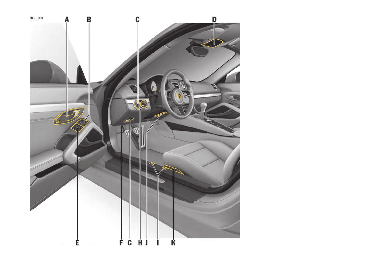
Driver’s Cockpit
A Door opener
See page 24.
B Exterior-mirror setting
See page 44.
C Light switch
See page 64.
D Overhead operating console
See page 154.
E Power windows
See page 61.
F Diagnostic socket (OBD)
See page 118.
G Electric parking brake
See page 120.
H Ignition lock
See page 118.
I Front and rear lid release
See page 24.
J Steering wheel adjustment
See page 46.
K Seat adjustment
See page 31.
12 Overview Illustrations
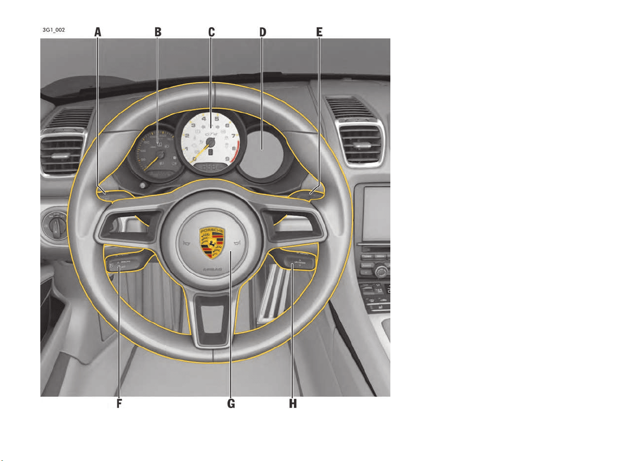
Steering Wheel and
Instrument Panel
A Turn signal lights
See page 66.
B Speedometer
See page 76.
Warning and indicator lights
See page 74.
C Tachometer
See page 76.
Warning and indicator lights
See page 74.
D Multi-function display
See page 76.
Warning and information messages
See page 109.
E Windshield wipers
See page 69.
F Cruise control
See page 124.
G Horn
H Telephone controls, multi-function display
See page 78.
Overview Illustrations 13
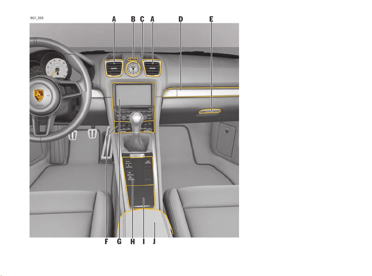
Center Console
A Air vents
See page 59.
B Emergency flasher switch
See page 67.
Central locking button
See page 22.
C Sport Chrono clock
See page 95.
D Drinks holder/cupholder
See page 144.
E Glove box
See page 143.
F Operating panel for air conditioning
See page 51.
G Porsche Communication Management (PCM)
See page 128.
H Control panel
See page 14.
I Ashtray, cigarette lighter, storage tray
See page 146.
J Storage tray
See page 144.
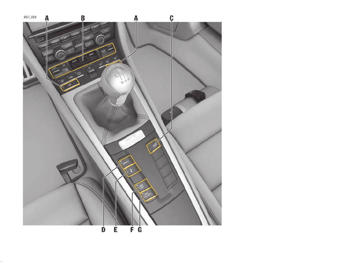
14 Overview Illustrations
Control Panel
A Heated seats/seat ventilation
See page 33.
B Control panel for air conditioning
See page 51.
C Sports exhaust system
See page 141.
D “Sport” mode
See page 141.
E Porsche Active Suspension Management
(PASM)
See page 139.
F Electronic Stability Control (ESC)
See page 137.
G Electronic Stability Control (ESC) und
Traction Control (TC)
See page 137.
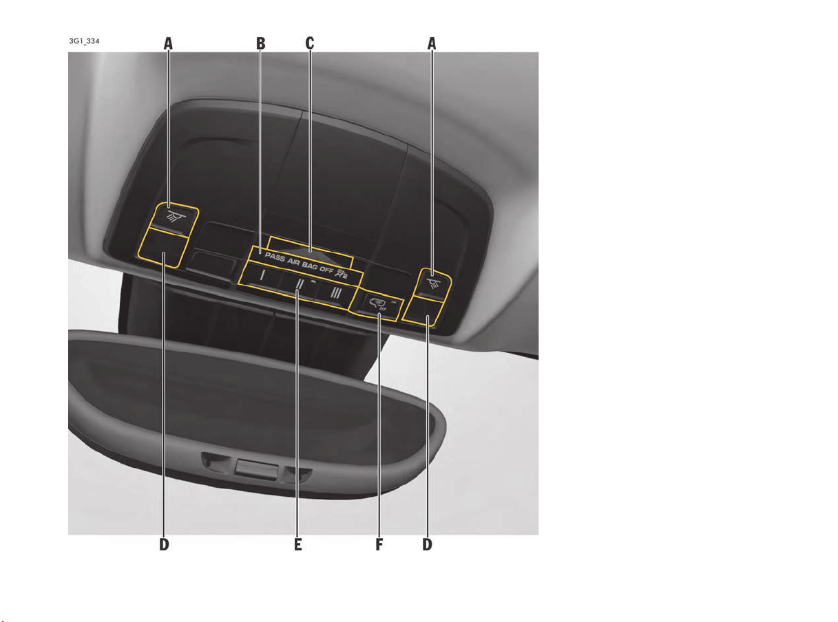
Overview Illustrations 15
Overhead Console
A Button for interior/reading lights
See page 67.
B PASS AIR BAG OFF warning light
See page 38.
C Interior light
See page 67.
D Reading lights
See page 67.
E Garage door opener (HomeLink
®
)
See page 154.
F Button for interior/reading lights
See page 68.

16 Opening and Locking
Opening and Locking
Never invite car theft! ....................................17
Notes on the Key and Central Locking System 18
Central Locking System ................................19
Brief Overview – Opening and Locking from
Outside ........................................................20
Opening and Locking from Outside.................21
Opening and Locking from Inside ...................23
Opening and Closing Luggage
Compartment Lids ........................................24
Malfunctions when Opening and Closing..........26
Trunk Entrapment .........................................29

Opening and Locking 17
Never invite car theft!
An unlocked car with the key in the ignition lock
invites car theft.
A gong alarm is standard equipment in your
Porsche. The gong alarm will sound if you open
the driver's door while the key is still in the ignition
lock. It is your reminder to pull the key out of the
ignition lock and to lock the doors.
Never leave your vehicle unattended with the key
in the ignition lock, especially if children and/or
pets are left unattended in the vehicle. They can
operate power windows and other controls. If the
engine is left running, they may accidentally
engage the shift lever. Serious personal injury or
death could result from loss of control of the
vehicle.
f Always remove the ignition key.
f Always set the electric parking brake.
f Lock the doors with the key or with the remote
control.
To protect your vehicle and your possessions
from theft, you should always proceed as
follows when leaving your vehicle:
f Close windows.
f Activate the electric parking brake.
f Remove ignition key (switch ignition off in
vehicles that have Porsche Entry & Drive).
f Remove valuables (e.g. car documents, radio
control module, cell phones, house keys) from
the car.
f Lock doors.
f Lock the glove compartment.
f Close storage trays.
Unattended vehicle
WARNING
h
18 Opening and Locking
Notes on the Key and Central
Locking System
Key
You are provided with two car keys with integrated
emergency key. These keys operate all the locks
on your vehicle.
f Be careful with your car keys: do not part with
them except under exceptional circumstances.
f Remove and take the ignition key with you,
even if leaving the vehicle only briefly.
Do not leave the ignition key in the vehicle.
f Inform your insurance company of any loss or
theft of car keys or if extra or replacement
keys have been cut.
f Third parties can still operate the mechanical
locks with a lost key.
Emergency operation
f Please see the chapter “EMERGENCY
OPERATION – UNLOCKING THE IGNITION KEY”
on page 27.
Replacement keys
Car keys can only be ordered through an
authorized Porsche dealer. Sometimes, this may
take a long time.
You should therefore always keep a spare key
convenient. Keep it in a safe place, but under no
circumstances in or on the vehicle.
The key codes of new keys have to be “taught”
to the vehicle control unit by an authorized
Porsche dealer. All keys belonging to the vehicle
must also be taught again for this purpose.
“Teach-in” can be carried out for a total of
8 vehicle keys.
Information
Third parties can continue to operate the
mechanical locks using the lost key.
f Please consult an authorized Porsche dealer
for blocking the lost key.
f Furthermore, it is recommended having the
mechanical locks replaced by an authorized
Porsche dealer.
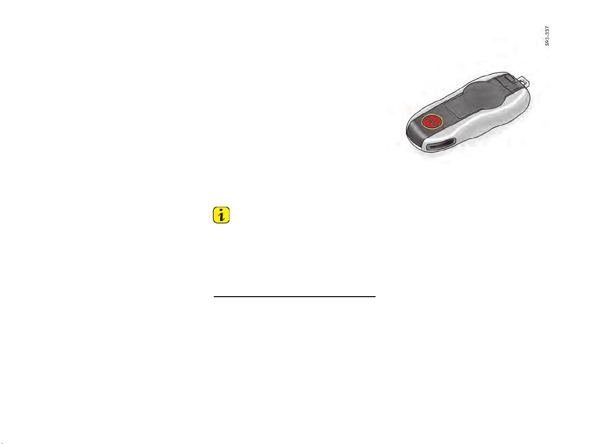
Panic button
In dangerous situations or when one's own safety
is threatened, it is possible to draw attention to
the situation by triggering an alarm.
To trigger an alarm
f Press button.
The horn sounds and the emergency flasher
flashes.
To stop the alarm
f Press button again or unlock the vehicle.
The horn becomes silent and the emergency
flasher goes out.

Opening and Locking 19
Emergency key
Removing emergency key
1. Push the release button to the side.
2. Pull out the key.
Inserting emergency key
f Slide in the key until the release button
audibly engages.
Central Locking System
This device complies with Part 15 of the FCC
Rules and RSS-210 of Industry Canada.
Operation of this device is subject to the following
two conditions:
1. This device may not cause harmful
interference, and
2. this device must accept any interference
received including interference that may cause
undesired operation.
Changes or modifications not expressly approved
by the party responsible for compliance could void
the user's authority to operate the equipment.
Information
The manufacturer is not responsible for any radio
or TV interference caused by unauthorized
modifications to this equipment.
Such modification could void the user's authority
to operate the equipment.
Any changes or modifications not expressly
approved by Porsche could void the user’s
authority to operate this equipment.
Your vehicle is equipped with a central locking
system. The following are unlocked or locked
together:
– Doors
– Filler flap
The central locking system is always activated
when the vehicle is unlocked and locked.
On the multi-function display of the instrument
panel, you can set different variants for locking
and unlocking. You can open all doors irrespective
of the setting made.
The vehicle cannot be locked if the driver’s door is
not completely closed.
If one of the following components is not
completely closed when you try to lock the vehicle
the door is not locked:
– vehicle doors
– luggage compartment lid
The indication by the emergency flasher and by
the acoustic signal will be provided after all doors
and the luggage compartment lid are closed.
Information
When locking the vehicle with only the driver's
door closed, the vehicle will be pre-locked. Make
sure that the key is not inside the vehicle when
closing the open passenger's door/luggage
compartment lid.
USA: KR55WK50138
Canada: 7812D-5WK50138
20 Opening and Locking
Brief Overview – Opening and
Locking from Outside
This brief overview does not replace the
information provided under “OPENING AND
LOCKING FROM OUTSIDE”.
Warnings, in particular, are not replaced by this
brief overview.
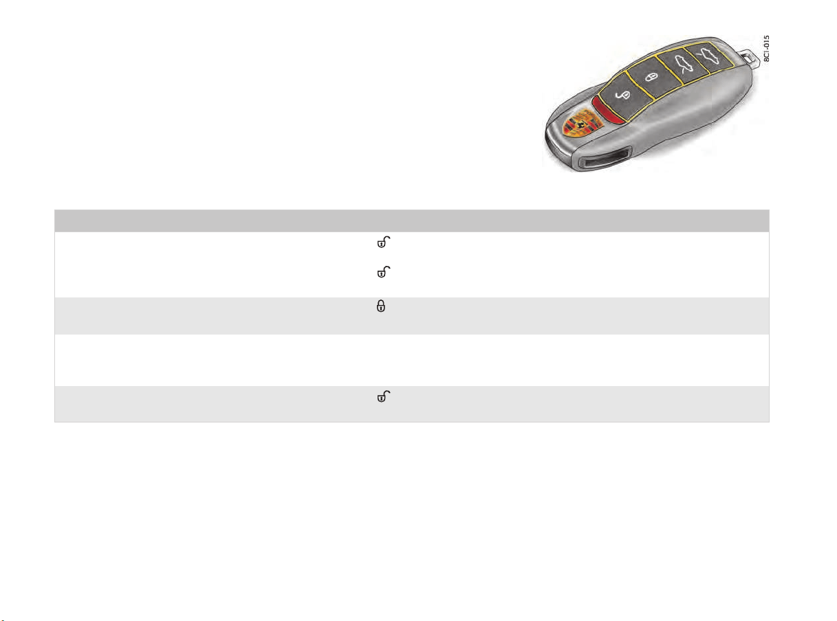
Key
What do I want to do? What do I have to do? What happens?
Unlocking Press the button on the key once.
Press the button on the key twice within
5 seconds.
The emergency flasher flashes once.
The driver’s door can be opened.
The emergency flasher flashes once.
Both vehicle doors can be opened.
Locking Press the button on the key.
The emergency flasher flashes twice.
The doors are locked.
Lock if persons/animals
are remaining in vehicle
(Switch off the alarm system’s interior surveillance)
Please see the chapter “SWITCHING OFF INTERIOR
SURVEILLANCE AND INCLINATION SENSOR”
on page 159.
Switching off alarm Press the button on the key to unlock the
vehicle.
The alarm stops.
Opening and Locking 21
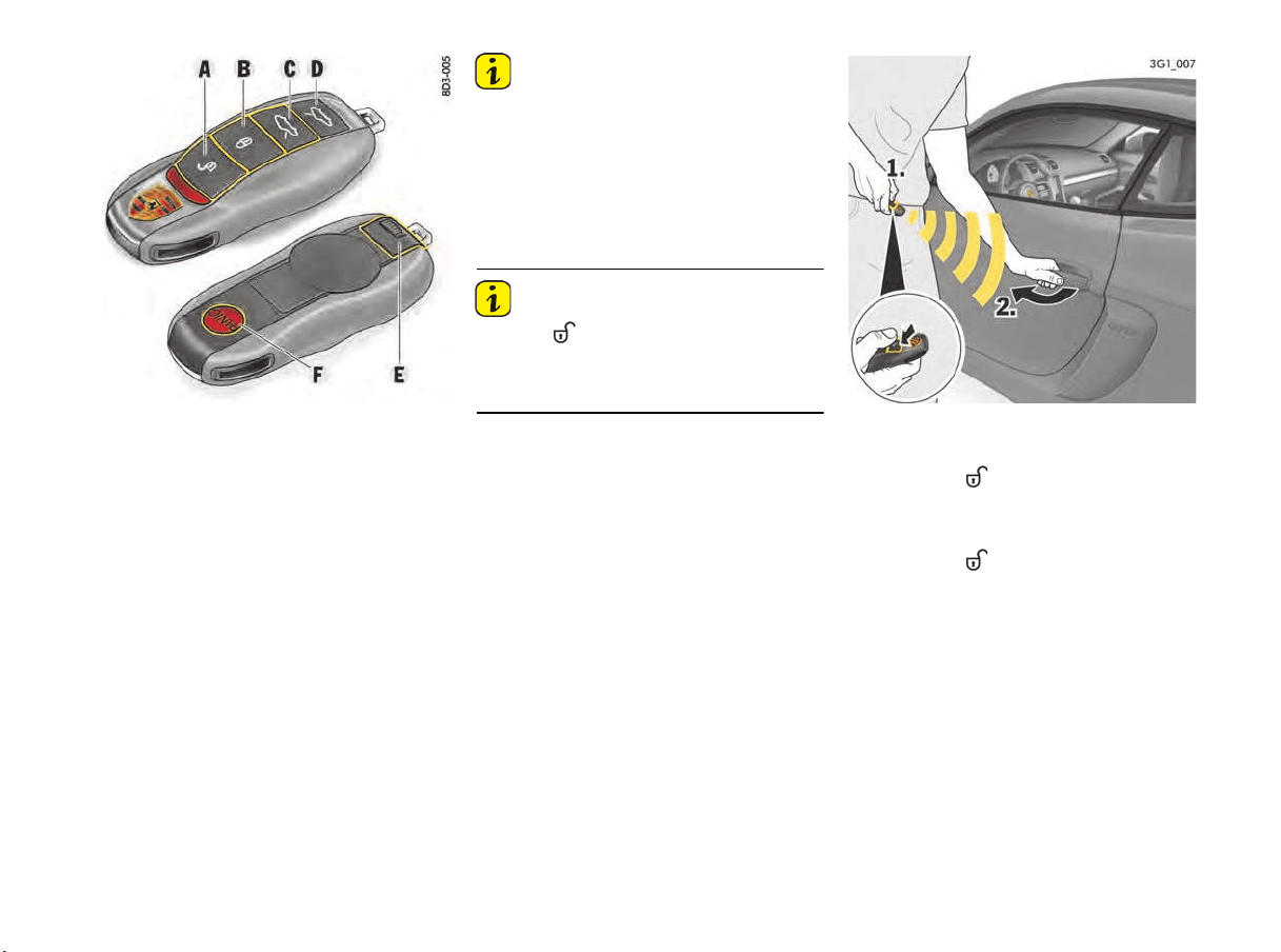
A - Unlocking the vehicle
B - Locking the vehicle
C - Unlocking the front luggage compartment lid
and doors
D - Unlocking the rear luggage compartment lid
and doors
E - Emergency key
F - Panic button
Opening and Locking from Outside
Use the buttons on the key to unlock and lock the
vehicle.
Information
If you unlock the vehicle with the emergency key in
the door lock, you must switch the ignition on
(ignition lock position 1) within 15 seconds of
opening the door in order to prevent the alarm
system from being triggered. The passenger’s
door remains locked.
The time it takes for the alarm system to be
triggered is country-dependent.
Information
If button A is pressed and a door or the
luggage compartment lid is not opened, the
vehicle is locked again automatically after
30 seconds.
Unlocking and opening doors
Unlocking with the key
1. Press button once.
The emergency flasher flashes once.
The driver’s door is unlocked.
or
Press button twice within 5 seconds.
The emergency flasher flashes once.
Both vehicle doors are unlocked.
2. Pull the door handle.
22 Opening and Locking
Information
The vehicle is locked automatically after
30 seconds if none of the doors or the luggage
compar
tment is opened.
If the interior surveillance system and inclination
sensor have been switched off (restricted anti-
theft protection), this also remains the case after
automatic relocking.
As a result, the doors can be opened from inside
by pulling the door opener.
f Inform any persons remaining in the vehicle
that the alarm system will be triggered if the
door is opened.
When locked again, the interior surveillance
system and inclination sensor are activated once
more.
Side-selective door unlock function
When unlocking the vehicle, you can choose to
unlock only the driver's door or also the
passenger's door. You can unlock both doors
irrespective of the selected setting.
f Press button on the key twice within
5 seconds.
For information on modifying the opening and
locking settings:
f Please see the chapter “LOCKING SETTINGS”
on page 104.
Locking doors
Locking with the key
1. Close the door.
2. Press button once.
The emergency flasher flashes twice and an
acoustic signal will sound twice.
The doors cannot be opened from outside.
or
If persons or animals are remaining in the
vehicle, press button twice within 2
seconds.
The emergency flasher emits one long flash.
The alarm system’s interior surveillance is
switched off.
The doors can be opened from inside by
pulling on the door opener.
f Inform any persons remaining in the vehicle
that the alarm system will be triggered if the
door is opened.
Information
When locking the vehicle with only the driver's
door closed, the vehicle will be pre-locked. Make
sure that the key is not inside the vehicle when
closing the open passenger's door/luggage
compartment lid.
Information
The emergency flasher indicates that the vehicle
has been locked successfully only when all the
doors, the engine compartment lid and the
tailgate are closed.
Information
The vehicle cannot be locked if any of the doors
or the luggage compartment are not completely
closed.
A warning signal sounds in the passenger
compartment and a warning message appears
on the multi-function display.
The key must be outside the vehicle when locking
the vehicle doors, otherwise the vehicle doors
cannot be locked.
If the key is out of range, the vehicle doors and the
luggage compartment can no longer be opened
after the vehicle is locked.
Automatic door locking and automatic door
unlocking
In an emergency situation where you need to exit
the car through an automatically locked door,
remember the following procedure to open the
door.
f Unlock the doors by pressing the central
locking button or
f Pull the inner door handle to open the door.
Emergency auto lock
override
WARNING
h
Opening and Locking 23
In the multi-function display of the instrument
panel, you have the option of selecting diverse
variants of automatic door locking and automatic
door unlocking.
For information on modifying the opening and
locking settings:
f Please see the chapter “LOCKING SETTINGS”
on page 104.
Opening and Locking from Inside
The factory settings of the vehicle are described
in this section.
In the multi-function display in the instrument
panel, you can change the settings and store them
on the respective key for vehicles with memory.
For information on modifying the opening and
locking settings:
f Please see the chapter “LOCKING SETTINGS”
on page 104.
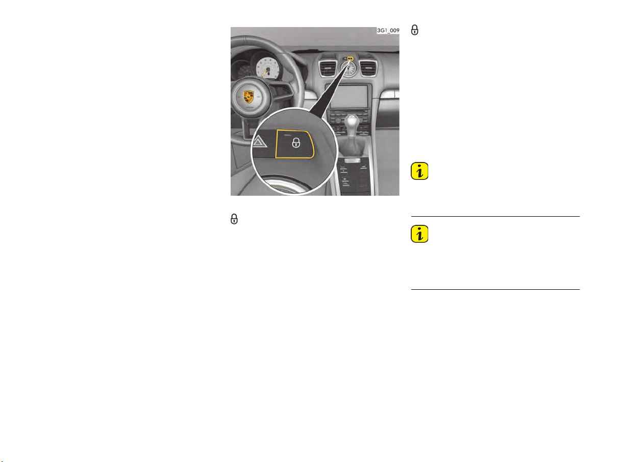
Central locking button
Locking doors
f Press the central locking button.
When the ignition is switched on, the indicator
light in the button lights up.
Both vehicle doors will be locked (only if all
doors are closed).
The doors can be opened from inside by
pulling on the door opener.
Automatic with Auto Lock
If this function is activated, the vehicle is locked
automatically when a speed of approximately
2 mph (5 km/h) is exceeded.
For information on modifying the opening and
locking settings:
f Please see the chapter “LOCKING SETTINGS”
on page 104.
Unlocking doors
f Press the central locking button.
The indicator light on the button goes out.
Both vehicle doors will be unlocked.
Automatic with Auto Unlock
The vehicle is automatically unlocked when the
ignition key is removed.
For more information on modifying the opening
and locking settings:
f Please see the chapter “LOCKING SETTINGS”
on page 104.
Information
If the vehicle was locked using the car key or the
emergency key, it cannot be unlocked with the
central locking button.
Information
In the event of an accident with airbag
deployment, the doors are unlocked automatically
to facilitate fast access for helpers. The
emergency flasher is also activated automatically.
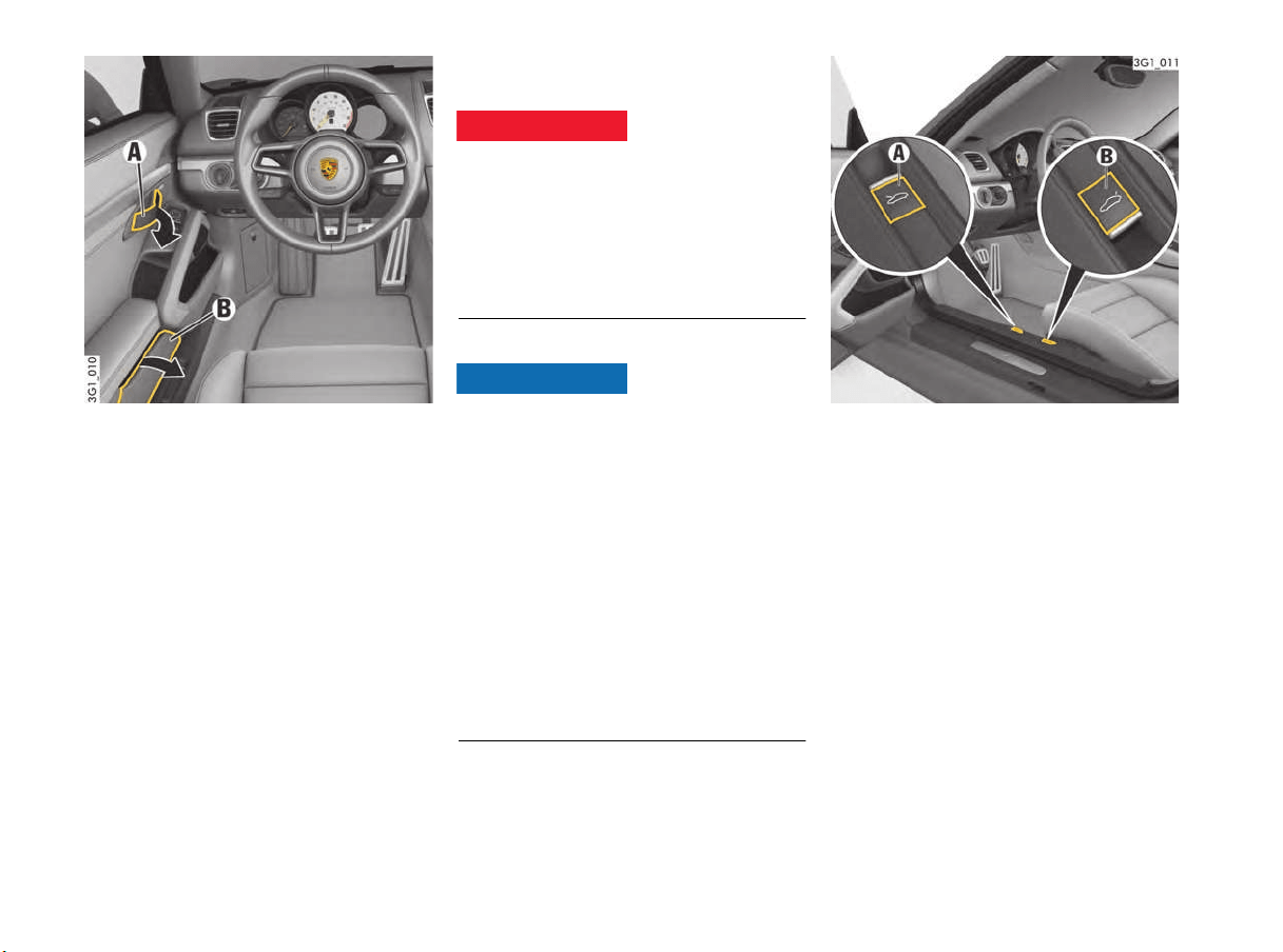
24 Opening and Locking
A - Door opener
B - Door storage tray
Opening doors
f Pull door opener (arrow) once.
Door storage tray
Opening storage tray
f Open the cover B.
Keep the storage tray closed while driving for
safety reasons.
Opening and Closing Luggage
Compartment Lids
If the luggage compartment lids are not secured
properly, they could fly up, blocking your vision
and causing loss of control.
f Should you notice at any time while driving that
one of the lids is not secured properly, please
stop immediately in a suitable place and close
it.
Opening front luggage compartment lid
Risk of damage to front luggage compartment lid
or windshield wipers.
If the windshield wipers are pulled forward when
you open the front luggage compartment lid, the
wipers or the luggage compartment lid could be
damaged.
f Make sure that the windshield wipers are not
pulled out forwards when opening the luggage
compartment lid.
f Always switch off windshield wipers before
opening the luggage compartment lid
(wiper switch in position 0).
For information on windshield wipers:
f Please see the chapter “WINDSHIELD WIPER
AND HEADLIGHT WASHER SYSTEM”
on page 70.
A - Front Luggage compartment lid
B - Rear Luggage compartment lid
1. Open the driver’s door.
2. Pull the release lever A next to the driver‘s
seat.
The front luggage compartment lid is now
unlocked.
Unsecured luggage
compartment lids
DANGER
h
NOTICE
Opening and Locking 25
3. Raise lid slightly and unlatch the safety catch
with the red lever (arrow).
4. Open the luggage compartment lid fully.
Closing front luggage compartment lid
1. Lower the lid and let it fall into the lock. Push the
lid closed with the palm of your hand in the area
of the lock.
2. Check that the lid has correctly engaged in the
lock.
When the vehicle is in motion, a message will
appear on the multi-function display in the
instrument panel if the lid is not closed properly.
Opening the rear luggage compartment
lid
1. Opening the driver’s door.
2. Pull the release lever B next to the driver‘s seat
The rear lid is unlocked.
3. Lift up the rear lid slightly and open.
Information
The rear lid can be held open in 2 positions.
f Position 1: Raise rear lid up to pressure point.
f Position 2: Raise rear lid beyond the pressure
point.
Closing the rear luggage compartment lid
1. Pull down the rear lid by the handle recess
(arrow) and allow it to fall into the lock. Then
press down on the lock area with the palm of
your hand.
2. Check that the rear lid has correctly engaged in
the lock.
When the vehicle is in motion, a message will
appear on the multi-function display in the
instrument panel if the rear lid is not closed properly.
Unlocking and opening front and rear
luggage compartment lid with the key
Information
When the front luggage compartment lid and/or
rear luggage compartment lid is unlocked, the
vehicle doors are also unlocked.
1. Press the or button.
The lid/rear lid is unlocked.
2. Lift up the lid/rear lid slightly and open. For the
front luggage compartment lid, additionally
unlatch the safety catch with the red lever.
26 Opening and Locking
Malfunctions when Opening and
Closing
Emergency operation of front luggage
compartment lid
If the vehicle battery is discharged, the front
luggage compartment lid can be opened only by
connecting an external electrical power source.
f Please see the chapter “EMERGENCY
UNLOCKING OF FRONT LUGGAGE
COMPARTMENT LID” on page 204.
Only one door is unlocked
The setting for locking and unlocking the doors
has been changed on the multi-function display in
the instrument panel.
f Please see the chapter “SETTING DOOR
UNLOCKING” on page 104.
You can open both doors irrespective of the
selected setting.
f Press button on the key twice within
5 seconds.
The vehicle cannot be unlocked
Remote control of the vehicle key may
– fail due to a fault,
– due to a flat key battery,
– not function correctly due to radio waves
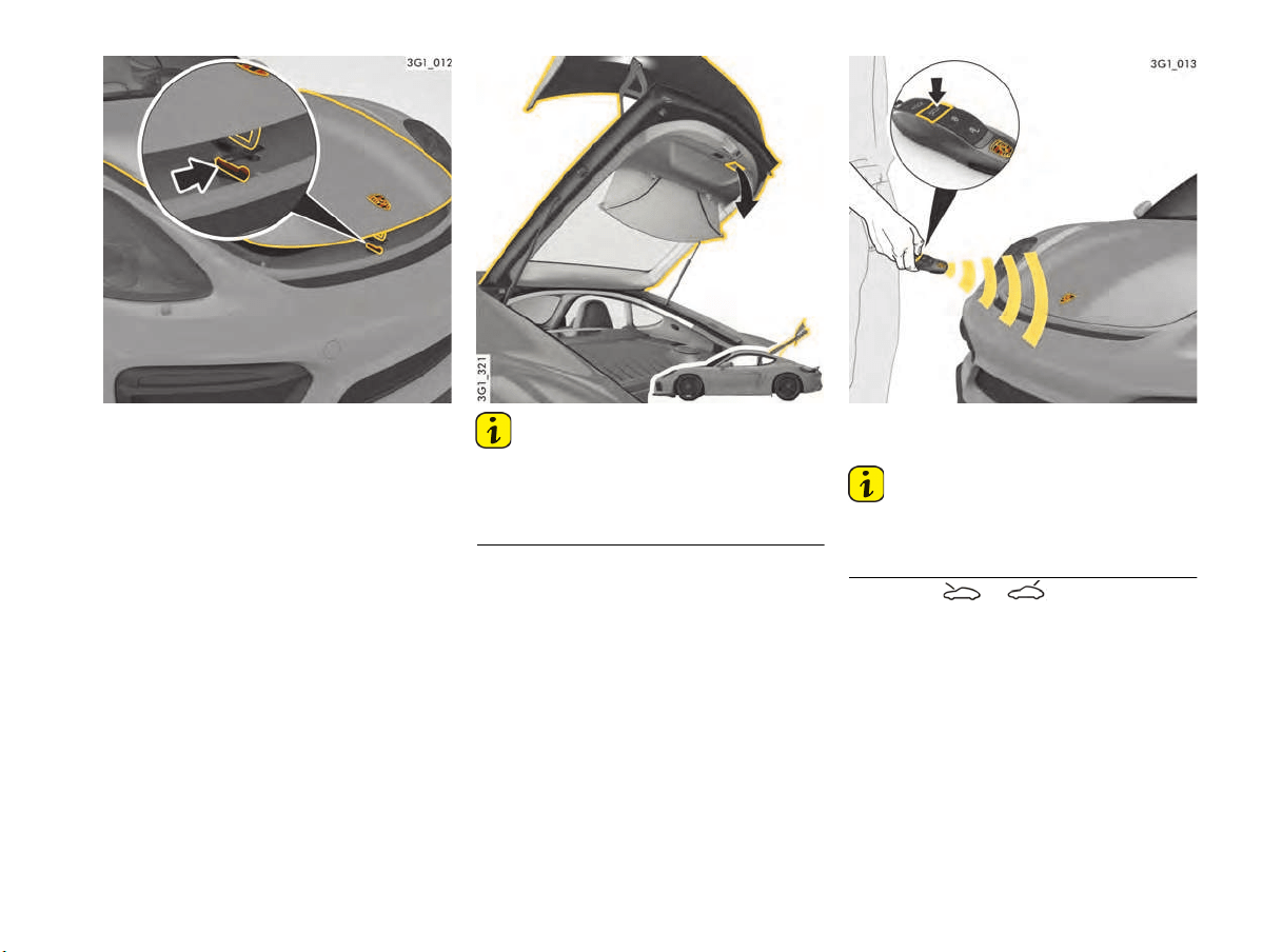
If the vehicle cannot be opened, then:
1. Place the vehicle key at the outside edge of the
windshield on the passenger’s side and, at
the same time, press button (illustration).
If the vehicle still cannot be opened, then:
2. Remove the emergency key from the vehicle
key.
Please see the chapter “EMERGENCY KEY”
on page 19.
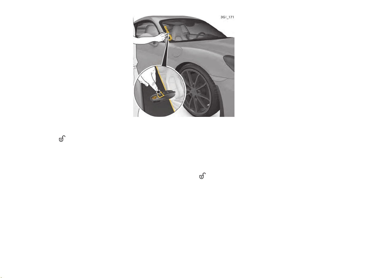
3. Unlock and open the driver’s door with the
emergency key.
For this purpose, lift and hold the door handle.
Insert the emergency key in the door lock, turn
90° anti-clockwise and remove the emergency
key again.
4. Release the door handle and open the door by
pulling the door handle again.
5. Switch on the ignition within 10 seconds to
prevent the alarm system from triggering.
Opening and Locking 27
Emergency operation – unlocking the
ignition key
If the vehicle battery is discharged, the ignition key
can be removed only if the emergency operation
is performed.
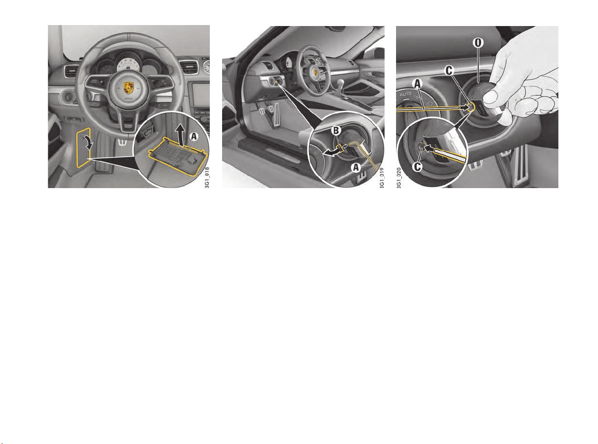
1. Grasp the fuse box cover on the driver’s side
at the finger hole and pull it off.
2. Unclip metal hook A on the inside of the fuse
box cover.
3. Use metal hook A to remove the plastic
cover B from the ignition lock.
Make sure not to lose the plastic cover B.
4. Ignition key to ignition lock position 0 (initial
position).
5. Press metal hook A into opening C.
You will hear an unlocking noise.
6. Remove the control unit/ignition key in initial
position 0.
7. Re-fit the plastic cover B.
28 Opening and Locking
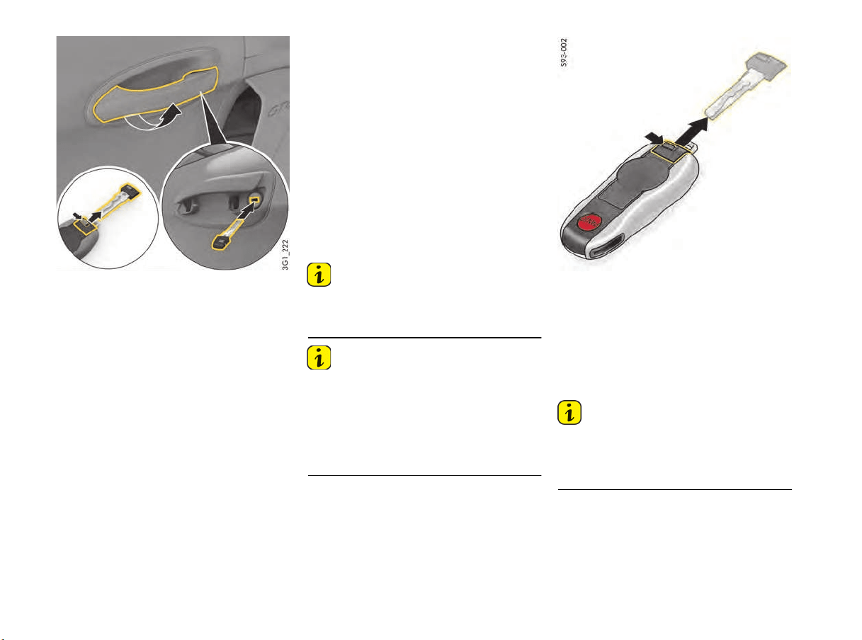
Door lock under door handle (driver‘s side)
The vehicle cannot be locked
This is recognizable by the fact that the
emergency flasher does not flash and there is no
locking noise.
The remote control of the key may
– fail due to a fault,
– due to a discharged key battery,
– not function correctly due to radio waves (e.g.
mobile phone) in the vicinity of the vehicle (also
radio contact between remote control and
vehicle in the case of Porsche Entry & Drive).
Emergency locking if the central locking
system has failed
If the vehicle cannot be locked, then:
1. Remove the emergency key from the vehicle
key.
Please see the chapter “EMERGENCY KEY”
on page 28.
2. Open the driver’s door.
3. Lift the door handle on the driver’s door
(ILLUSTRATION).
Insert the emergency key in the door lock, turn
90° clockwise and remove the emergency key
again.
Successful locking is indicated by the
emergency flasher flashing twice.
4. Release the door handle and shut the door.
The driver's door is now locked.
5. To lock the passenger’s door using the
emergency procedure, insert the emergency
key in the door lock in the driver’s door again,
turn 90° clockwise and remove the emergency
key again.
The passenger’s door is now locked.
6.
Information
The passenger’s door cannot be locked using
the emergency procedure if the central locking
system is defective.
Information
If the central locking system is defective,
operating the lock cylinder in the driver’s door will
lock all functioning locking elements of the central
locking system.
f Have the fault in the central locking system
remedied at your nearest authorized Porsche
dealer.
Emergency key
Removing emergency key
1. Push the release button to the side.
2. Pull out the key.
Insert emergency key
f Push in the key until the release button
engages audibly.
Information
Different vehicle settings are stored on the
respective key when the vehicle is locked,
provided the vehicle is fitted with the relevant
equipment.
Opening and Locking 29
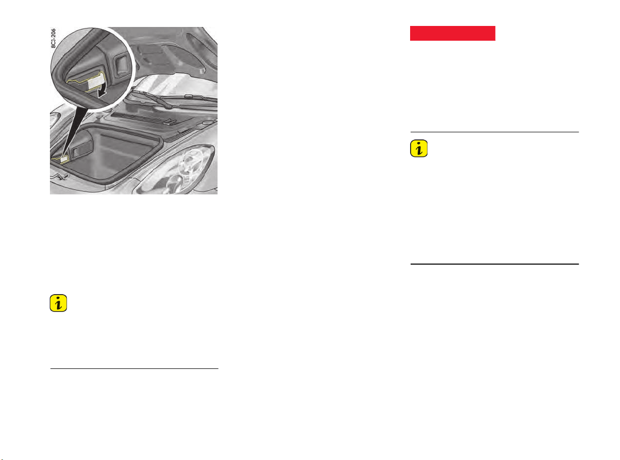
Unlocking handle in the front luggage compartment
Trunk Entrapment
Your vehicle is equipped with an internal trunk
release mechanism.
A person trapped in the front luggage
compartment can release the lid from the inside
using the unlocking handle.
The handle is fluorescent and glows in the dark.
Information
f When loading the luggage compartment, make
sure that items of luggage or other objects
cannot become caught on the handle.
This could cause the luggage compartment to
open unintentionally.
Function
If the luggage compartment lid is unlocked with
unlocking the handle,
the
lid can be opened from
the inside immediately.
A warning message in the multi-function display
lights up when unlocking handle is operated.
f Stop the vehicle immediately when the warning
message lights up.
f Check the luggage compartment.
f Close the lid.
If the warning message in the multi-function
display lights up when the vehicle is in motion, the
lid may impact in front of the windshield and can
tear off.
f Stop the vehicle immediately when the warning
message lights up.
f Check the luggage compartment.
f Close the lid.
Information
The lid cannot be opened from the inside if the
battery is disconnected or empty.
Safety reasons require that you unscrew the
latch striker of the lid lock if you plan to put
the vehicle out of operation for an extended
period.
f Please consult your authorized Porsche
dealer.
They will advise you about the necessary
measures.
Unsecured luggage
compartment lids
DANGER
h

30 Seats, Mirrors and Steering Wheel
Seats, Mirrors and Steering Wheel
Seat Adjustment and Head Restraints.............31
Seats...........................................................31
Seat Heating ................................................33
Safety Belts..................................................33
Airbag Systems ............................................35
Child Restraint Equipment..............................39
Top Tether ...................................................43
Exterior Mirrors ............................................44
Interior Mirror ...............................................45
Steering Wheel Adjustment ............................46
Sun Visors....................................................47
Vanity Mirror.................................................47

Seats, Mirrors and Steering Wheel 31
Seat Adjustment and Head
Restraints
Safety belts only offer protection when the
backrest is upright and the belts are properly
positioned on the body.
Improperly positioned safety belts or safety belts
worn by passengers in an excessively reclined
position can cause serious personal injury or
death in an accident.
f Do not operate the car with the driver or
passenger backrests excessively reclined.
f Please see the chapter “SEAT POSITION”
on page 31.
The seat may move further than desired if you
adjust it when driving. You could lose control of the
vehicle.
f Do not adjust seats while the vehicle is in mo-
tion.The backrest locks must be engaged at all
times while the vehicle is in motion.
If persons or animals are in the movement range
of the seat during seat adjustment, parts of the
body could get trapped or crushed.
f Adjust the seat so that no-one is put a risk.
f Do not activate the comfort memory button if
there is any risk of the seat crushing the
occupant.
f Cancel automatic adjustment by pressing any
of the seat adjustment buttons.
f Do not leave children in the vehicle unattended,
since they may depress the setting buttons
and crush themselves or another occupant.
Risk of damage to windshield, sun visor, etc. when
the seat is adjusted or folded back or forward.
f Adjust the seat so that the seat backrest is not
in contact with any other object.
The driver and passenger seats provide
integrated head restraints in the backrests. The
head restraints are not adjustable.
All occupants, including the driver, should not
operate a vehicle or sit in a vehicle’s seat until the
headrests and backrests are placed in their
proper positions so that the risk of neck injuries is
minimized in the event of a crash.
f Adjust the backrest's inclination such that the
headrest is in an upright position.
f Driver and passengers should be seated
upright and in the center of their seats.
Seats
Seat position
An ergonomically correct sitting position is
important for safe and fatigue-free driving. We
recommend the following procedure for adjusting
the driver’s seat to suit individual requirements:
1. Adjust the seat height to give yourself enough
headroom and a good overview of the vehicle.
2. Adjust the seat in fore-and-aft direction so that
your leg is not fully straight and your entire foot
is on the pedal when pressing the pedals fully.
3. Grip the top half of the steering wheel. Set the
backrest angle (backrest angle is not
adjustable at the full bucket seat) and the
steering wheel position so that your arms are
almost outstretched. However, your shoulders
must still rest on the backrest.
4. Adjust the seat fore-and-aft setting if
necessary.
Adjusting the seat
The seat may move further than desired if you
adjust it when driving. You could lose control of the
vehicle.
f Do not adjust seats while the vehicle is in mo-
tion.The backrest locks must be engaged at all
times while the vehicle is in motion.
If persons or animals are in the movement range
of the seat during seat adjustment, there is a risk
of parts of the body being squeezed or crushed.
f Adjust the seat so that no-one is put at risk.
Improper safety belt use
Seat adjustment while
driving
Seat adjustment
DANGER
h
WARNING
h
CAUTION
h
Failure to adjust head
and backrests
NOTICE
WARNING
h
Seat adjustment while
driving
Seat adjustment
WARNING
h
CAUTION
h
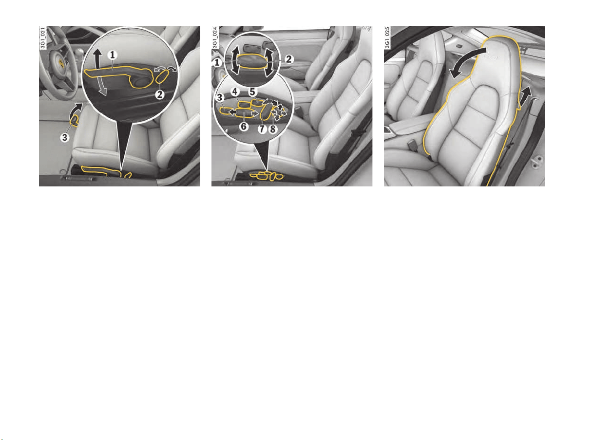
32 Seats, Mirrors and Steering Wheel
Sports seat/Sports seat plus
1 Height adjustment
f Use lever 1 in a pumping movement:
Upwards = seat moves upwards
Downwards = seat moves downwards
2 Backrest angle
Operate switch 2 until the desired backrest
angle is reached.
3 Fore-and-aft adjustment
f Pull up locking lever 3.
Move seat to desired position and release
lever.
Ensure that the seat engages correctly.
Adaptive sports seat plus
1 Seat angle adjustment
2 Height adjustment
3 Thigh support adjustment
4 Seat cushion side bolster adjustment
5 Backrest side bolster adjustment
6 Fore-and-aft adjustment
7 Backrest angle adjustment
8 Lumbar support adjustment
f Press each control in the direction indicated by
the arrows until the desired setting is reached.
Seat backrest
Folding forward
f Pull up lever in the side part of the backrest
and fold the backrest forward.
Folding back
f Tilt back and engage the backrest so that it
cannot tip forward when you brake.
Seats, Mirrors and Steering Wheel 33
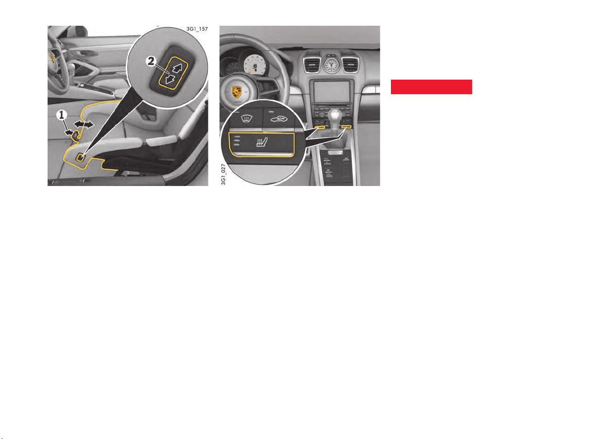
Full bucket seat
Child restraint systems must not be used on
full bucket seats.
1 Fore-and-aft adjustment
f Pull up locking lever 1.
Move seat to desired position and release
lever.
Ensure that the seat engages correctly.
2 Height adjustment
f Press the control 2 in the direction indicated
by the arrows until the desired settings or the
limit position is reached.
Seat Heating
The seat heating is ready for operation when
the engine is running. The heating power can be
adjusted to one of three settings by repeatedly
pressing the heated seat button.
Switching on
f Press heated seat button (repeatedly).
The number of illuminated indicator lights
shows the selected heat setting.
Switching off
f Press the heated seat button (repeatedly)
until all indicator lights go out.
Seat heating is not available when the interior
temperature is high.
If the charging condition of the battery is critical,
the seat heating function is restricted initially and
then switched off.
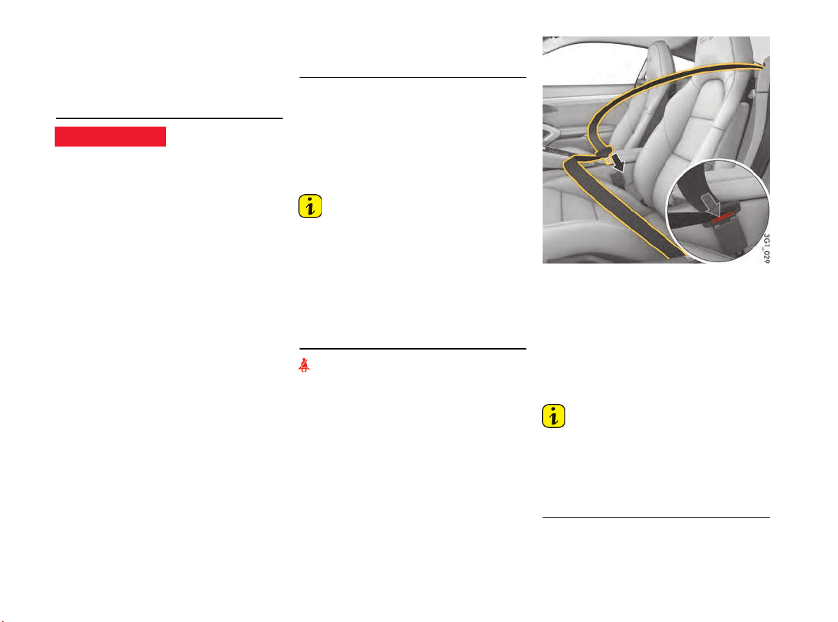
Safety Belts
Safety belts help protect occupants during
accidents. They are the most important part of the
restraint system. Most states require the use of
safety belts at all times.
Safety belts do not offer any protection in the
event of an accident if they are not worn.
Incorrectly fastened safety belts can increase the
risk of injury in the event of an accident.
f All occupants of the vehicle must wear safety
belts for their own safety. Share all the informa-
tion in this section with your passengers.
f Use appropriate child restraint systems for all
children.
f Safety belts must be positioned on the body as
to restrain the upper body and lap from sliding
forward. Improperly positioned safety belts
can cause serious personal injury in case of an
accident.
f The shoulder belt should always rest on your
upper body. The shoulder belt should never be
worn behind your back or under your arm.
f For maximum effectiveness, the lap belt
should be worn low across the hips.
f Pregnant women should position the belt as
low as possible across the pelvis. Make sure it
is not pressing against the abdomen.
f Never use one safety belt for two persons at
the same time.
f Remove any loose, bulky items of clothing that
prevent the belt form fitting correctly.
f Belts should not be worn twisted or loose.
f Do not lay the belt across hard or breakable
objects (glasses, ball-point pens, pipes, etc.).
Unfastened or
incorrectly used safety
belts
DANGER
h
34 Seats, Mirrors and Steering Wheel
Such objects, can constitute an additional risk
to occupants’ safety
.
f Several layers of heavy clothing may interfere
with proper positioning of belts.
f Belts must not rub against sharp objects or
damage may occur to the belt.
Damaged, heavily stressed or worn safety belts
cannot protect the body sufficiently in the event of
an accident.
f Check all belts regularly for signs of damage in
the fabric, and check that the buckle and
attachment points function correctly.Keep belt
buckles free of any obstruction that may
prevent a secure locking.
f Belts that have been subjected to excessive
stretch forces in an accident must be
inspected or replaced to ensure their
continued effectiveness in restraining you.
The same applies to belt tensioner systems
which have been triggered. In addition, the
anchor points of the belts should be checked.
f If safety belts do not work properly, see your
authorized Porsche dealer immediately.
f If the belts show damage to webbing, bindings,
buckles or retractors, they should be replaced
to ensure safe operation.
f Do not modify or disassemble the safety belts
in your vehicle.
f The belts must be kept clean or the retractors
may not work properly.
Please see the chapter “CLEANING THE
SAFETY BELTS” on page 180.
f Never bleach or dye safety belts.
f Do not allow safety belts to retract until they
are completely dry after cleaning or this may
cause damage to the belt.
Safety-belt pretensioner
Safety safety-belts are tightened in an accident,
depending on the force of the collision.
The safety-belt pretensioners are triggered:
– In the event of front and rear impact
– In the event of side impact
– If the vehicle turns over
Information
The safety-belt pretensioner system can be
triggered only once; the system must then be
replaced.
Work may be carried out on the safety-belt
pretensioner system only by an authorized
Porsche dealer.
Smoke is released when the safety-belt
pretensioners are triggered. This does not
indicate a fire in the vehicle.
Warning light and warning message
An audio-visual warning system is
interconnected with the driver’s and passenger's
safety belt.
The following functions serve as a reminder to
fasten the safety belts; they remain active until the
tongue of the driver's or passenger's safety belt is
inserted into its buckle:
f The warning light on the instrument panel lights
up when the ignition is switched on.
f A warning appears on the multi-function display
in the instrument panel.
f A warning signal (gong) sounds when the
vehicle speed exceeds 24 km/h (15 mph).
Fasten safety-belt
1. Assume a comfortable sitting position.
2. Adjust the seat backrest (backrest angle is not
adjustable at the full bucket seat) so that the
belt always rests on your upper body and runs
across the middle of your shoulder.
3. Grasp the belt tongue and pull the belt in a
slow, continuous motion across your chest
and lap.
Information
The belt may be blocked if the vehicle is standing
at an angle or the belt is pulled out using a jerking
movement.
The belt cannot be pulled out while accelerating
and slowing down, when cornering and when
driving uphill.
4. Insert the belt tongue into the appropriate
buckle on the inboard side of the seat until it
locks securely with an audible click.
Using damaged safety
belts
DANGER
h
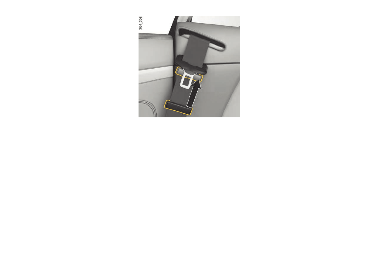
Seats, Mirrors and Steering Wheel 35
5. Make sure that belts are not trapped or twisted
and that they are not rubbing on sharp edges.
6. The horizontal section of the belt should
always fit snugly across the pelvis. Therefore,
after fastening the belt, always pull the
diagonal part of the belt upward.
Pregnant women should position the belt as
low as possible across the pelvis, and ensure
that it is not pressing against the abdomen.
7. Also pull on the diagonal section of the belt
now and again during the journey to ensure
that the horizontal section remains tight.
Opening belt buckle and removing belt
1. Hold the belt tongue.
2. Press the red button on the belt buckle.
3. Guide the belt tongue to approx. 7 cm below
the deflection bracket of the strap reel (figure)
and lock using the plastic slide (figure). The
function of the plastic slide is to hold the belt
tongue in an easily accessible position.
Airbag Systems
The vehicle is equipped with airbags and lap/
shoulder belts at both front seating positions. The
airbags are a supplemental restraint at those
seating positions.
The airbags in combination with the safety belts
make up a safety system which offers the driver
and the passenger the greatest known protection
from injuries in case of an accident.
Your vehicle is equipped with occupant sensing for
the passenger's seat in accordance with
U.S. Federal Motor Vehicle Safety Standard 208.
Even though your vehicle is equipped with airbags,
the safety belts must be worn at all times,
because the front or side airbags deploy
depending on the force and angle of impact.
Below the deployment threshold of the airbag
system, and during types of collisions which do
not cause the airbag deployment, the safety belts
provide the primary protection to the occupants
when correctly worn. Therefore, all persons
within the vehicle must wear safety belts at
all times to minimize the risk of severe injury or
death in the event of a crash.
f Please see the chapter “SAFETY BELTS”
on page 33.

36 Seats, Mirrors and Steering Wheel
The fr
ont airbags are located under the padded
steering wheel panel on the driver’s side, in the
dashboard on the passenger's side, and in the
knee area for both the driver and the passenger.
The side airbags are installed on the side in the
seat backrests.
The head airbags are installed in the door linings.
Information
To minimize the risk of severe injury or death in the
event of a crash, all occupants, including the
driver, should always wear their safety belts
whether or not an airbag is also provided at their
seating position.
Airbags only can offer protection, if all occupants
fasten their safety belts and retain a proper sitting
position.
To provide optimal occupant protection, airbags
must inflate at very high speed. If you are not
wearing your safety belt or are too close to the
airbag when it is deployed, inflating airbags can
result in serious personal injury or death.
f Always fasten safety belts.
f Make sure there are no people, animals or
objects between the driver or passenger and
the area into which the airbags inflate.
f Sit back as far from the dashboard or steering
wheel as is practical, while still maintaining full
vehicle control.
f Always hold the steering wheel by the outer
rim. Never rest your hands on the center of the
steering wheel where the airbag module is
located.
f Always keep feet in the footwell while driving.
Do not put feet on the dashboard or the seat
area. Do not lean against the inside of the door
or outside the window while the vehicle is
moving.
Objects and load have to be stored securely to
keep from causing injury.
f Do not transport heavy objects on or in front of
the passenger seat. These could impair the
function of the airbags, the safety belts, and
occupant sensing.
f Do not hang objects (e.g., jackets, coats, coat
hangers) over the backrest.
f Objects must not protrude out of the door
storage compartment.
f Do not add any additional coverings or stickers
to the steering wheel or in the area of the
passenger airbag, side airbags, knee airbags,
and head airbags. Doing so may adversely
affect the functioning of the airbag system or
cause harm to the occupants if the airbag
system should deploy.
Do not use protective seat covers.
f No objects should be placed over or near the
airbag on the instrument panel, because any
such objects could cause harm if the vehicle is
in a crash severe enough to cause the airbag
to inflate.
f Give your passenger all of the information in
this chapter.
A modified airbag system cannot offer protection.
They may not trigger or could trigger in an
uncontrolled way. An uncontrolled triggering of the
airbag system can result in serious personal injury
or death.
f Do not modify the seat coverings, since such
changes can block the seat-mounted side
airbag. Do not attach additional cushions,
protective coverings, or pillows to the seats.
Do not affix things to the seats or cover them
with other materials. Do not cover the back of
the backrest. Do not make changes to the
seats, the cushion or foam, the occupant
sensor, and to the seat base frame.
f No changes must be made to the wiring or
components of the airbag system. Doing so
may disable the airbag system or cause
inadvertent inflation.
f Do not install any wiring for electrical
accessory equipment in the vicinity of the
airbag wiring harnesses. Doing so may disable
the airbag system or cause inadvertent
inflation.
f If the warning light comes on, the airbag
system should be repaired immediately by
your authorized Porsche dealer.
f Using accessories not approved by Porsche
can cause the occupant sensing to be
impaired.
f Do not squeeze objects, such as the fire
extinguisher, or first aid kit under the seat.
f Only have seats removed and installed by an
authorized Porsche dealer so that occupant
sensing components will not be damaged.
Safety belts and
positioning
DANGER
h
Safe storage of objects
DANGER
h
Modification to airbag
system
DANGER
h

Seats, Mirrors and Steering Wheel 37
Airbag systems were designed to trigger only
once.
f Have triggered airbag systems replaced
immediately.
Information
Airbag components (e.g. steering wheel, door
lining, seats) may be disassembled only by an
authorized Porsche dealer.
f When disposing of a used airbag unit, our
safety instructions must be followed. These
instructions can be obtained at any authorized
Porsche dealer.
Function of the airbag system
Airbags are a supplemental safety system. Your
primary protection comes from your safety belts.
The front airbags are triggered during a frontal
collision of sufficient force and direction.
In the event of a side impact of corresponding
force, the side airbag on the impact side is
triggered.
The inflation process generates the amount of gas
required to fill the airbags at the necessary
pressure in fractions of a second.
Airbags help to protect the head and body, while
simultaneously damping the motion of the driver
and passenger in the impact direction in the event
of a frontal impact or side impact.
In order to help provide protection in severe
collisions which can cause death and serious
injury, airbags must inflate extremely rapidly. Such
high speed inflation has a negative but
unavoidable side effect, which is that it can and
does cause injuries, including facial and arm
abrasions, bruising and broken bones. You can
help minimize such injuries by always wearing your
safety belts.
There are many types of accidents in which
airbags are not expected to deploy. These include
accidents where the airbags would provide no
benefit, such as a rear impact against your
vehicle. Other accidents where the airbags are
designed not to deploy are those where the risk of
injury from the airbag deployment could exceed
any protective benefits, such as in low speed
accidents or higher speed accidents where the
vehicle decelerates over a longer time. Since
airbag deployment does not occur in all accidents,
this further emphasizes the need for you and your
passengers to always wear safety belts.
Your Porsche vehicle is equipped with
electronically controlled systems that help to
ensure your vehicle operates properly. These
systems monitor the operation of various systems
and electronically store information that is useful
to service technicians when they need to diagnose
and repair these systems.
Your vehicle is equipped with crash-sensing
and diagnostic devices that may record
information at the time of a collision,
including whether the airbag and seatbelt
pretensioners deployed and whether the
safety belt was in use.
To retrieve this information, special equipment is
needed and access to the vehicle or feature that
stores that data is required. Some states only
allow access to such information under restricted
circumstances, including:
– In response to a request of police or other
government office; or
– with the consent of the registered owner, or if
the vehicle is leased, with the lessee, or
– through a discovery process in litigation; or as
otherwise permitted or required by law.
Your rights with respect to the information
discussed above may vary from state to state.
Check your state law for further information.
Advanced airbag
Your vehicle is equipped with occupant sensing for
the passenger's seat in accordance with
U.S. Federal Motor Vehicle Safety Standard 208.
The components of the advanced passenger
airbag system include an occupant sensing
system for the front passenger seat and a
PASS AIR BAG OFF indicator lamp.
Depending on the weight, body positioning and
shape acting on the passenger's seat, the
passenger’s airbag will automatically be switched
on and off.
Depending on the angle and force of impact, the
passenger's airbag which is switched-on will be
triggered during a collision.
Precondition for switching the passenger's airbag
on and off, depending on weight, body positioning
and shape:
– Ignition is switched on.
No Activation of already
triggered Airbag
Systems
DANGER
h
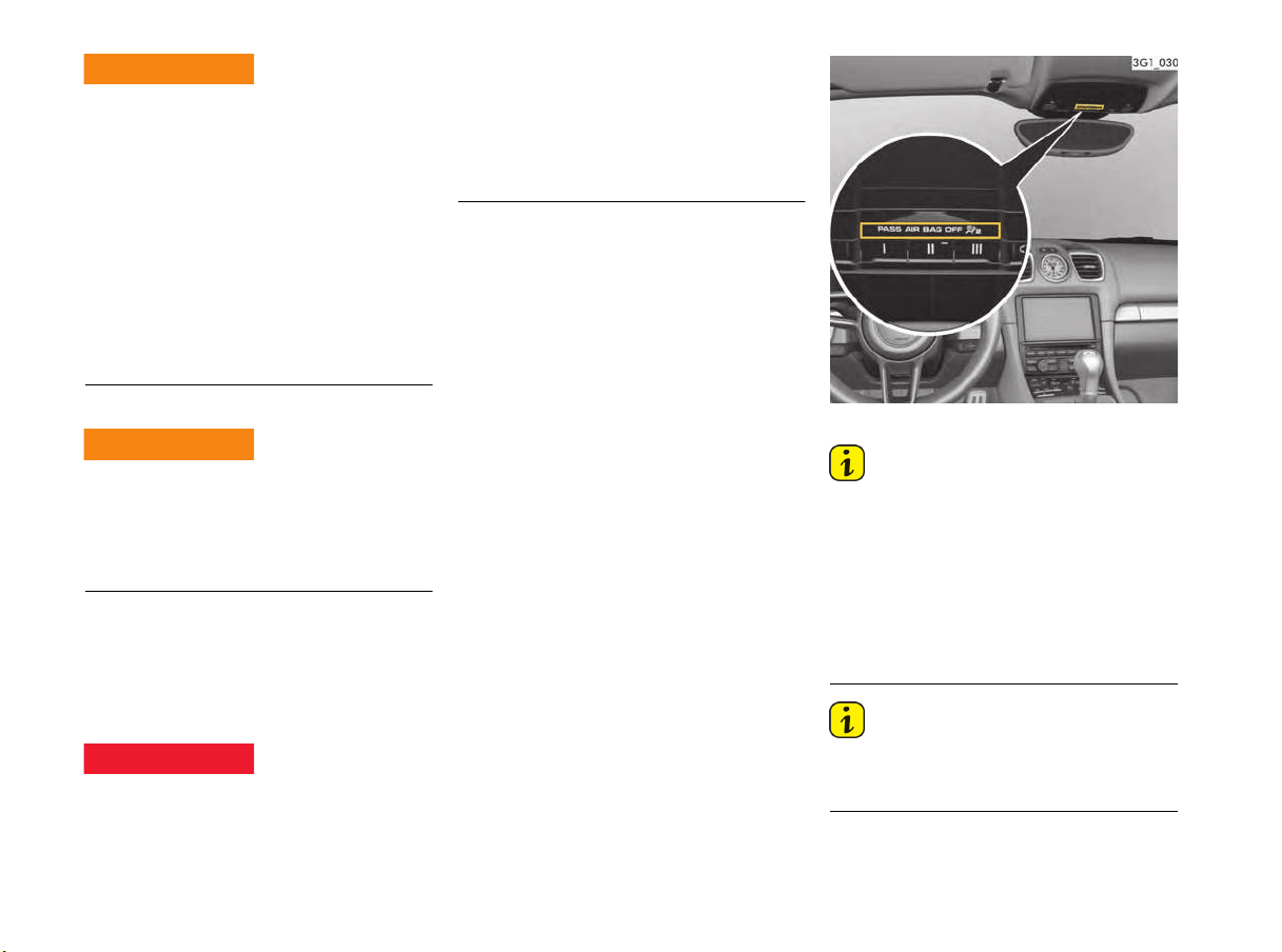
38 Seats, Mirrors and Steering Wheel
Improper seating can unintentionally impair
operation of occupant sensing of the passenger’
s
airbag.
If the weight of an adult on the passenger's seat is
not properly maintained, the passenger's airbag
may be switched off.
f Select an upright seat position, and do not
support weight on the armrests or center
console, or lean out of the window while
driving.
Always keep feet positioned on the floor in the
footwell while driving. Do not put feet on the
dashboard or the seat area.
Seat adjustment for the passenger’s seat
Safety belts only offer protection when the
backrest is positioned at an upright seating angle
and the belts are properly positioned on the body.
f Do not operate the car with the driver or
passenger backrests excessively reclined.
Vehicle modifications to accommodate
persons with disabilities
Because modifications to your vehicle could
compromise your advanced airbag system,
please call 1-800-PORSCHE prior to having your
vehicle modified.
To reduce risk of injury or death to a child from an
inflating airbag in an accident, Porsche strongly
recommends:
f Please see the chapter “PASS AIR BAG OFF
INDICATOR LAMP DOES NOT ILLUMINATE”
on page 39.
f Before transporting a child on the passenger‘s
seat:
Please see the chapter “CHILD RESTRAINT
SYSTEMS” on page 39.
Automatic deactivation of the passenger
airbag
Before transporting a child on the passenger seat:
f Please see the chapter “CHILD RESTRAINT
SYSTEMS” on page 39.
– When an up to one-year old child is seated
in the child restraint system, the front airbag is
automatically deactivated on the passenger
side.
– When an adult is seated in the passenger’s
seat the front airbag is automatically activated.
PASS AIR BAG OFF indicator lamp
Information
Depending on the weight, body positioning and
shape acting on the passenger's seat, it can occur
in the case of heavier children that the passenger
airbag is active or, in the case of very light adults
or young persons, that the passenger airbag is
deactivated.
The condition of the passenger airbag system is
shown by the indicator lamp in the overhead
operating console.
Information
f After switching on the ignition, the PASS AIR
BAG OFF warning light lights up for a few
seconds as a check.
Improper passenger
seating
Reclining passenger
seatback
Inflating airbags
WARNING
h
WARNING
h
DANGER
h
Seats, Mirrors and Steering Wheel 39
PASS AIR BAG OFF indicator lamp illuminates
– The passenger airbag is switched off.
PASS AIR BAG OFF indicator lamp does not
illuminate
– The passenger airbag is active and ready for
operation.
Risk of serious personal injury or death due to the
passenger airbag triggering unintentionally.
When the ignition is on and the up to one-year old
child is seated in the child restraint system on the
passenger seat the indicator lamp
“PASS AIR BAG OFF“ must be on.
If the “PASS AIR BAG OFF” indicator lamp does
not light up, it could indicate a fault in the system,
and the airbag could inflate in a collision, placing
the child at risk of death or severe injury from the
inflating airbag.
In this case:
f Do not install a child restraint system on the
passenger‘s seat.
f Have the fault remedied at your nearest
authorized Porsche dealer.
Airbag Warning light
Faults are indicated by a warning light on the
tachometer.
The airbag warning light illuminates when the
electronic monitoring of the airbag system
detects a malfunction of the sensors, safety belt
system, occupant detection system, PASS AIR
BAG OFF indicator lamp, related wiring, airbag
modules and control units.
f In the following cases you should
immediately consult an authorized
Porsche dealer in order to assure the
airbag system is functioning properly:
– If the warning light does not light up when the
ignition is switched on or
– If the warning light does not go out once the
engine is running or
– If the warning light appears while driving.
Information
If you sell your Porsche, notify the purchaser that
the vehicle is equipped with airbags, and refer
them to the chapter “Airbag systems“ in the
Owner’s manual (safety and disposal rules).
Further information on the airbag system can be
found on stickers attached to the sun visors, as
well as on all airbag components.
For special recommendations on the use of child
restraints:
f Please see the chapter “CHILD RESTRAINT
SYSTEMS” on page 39.
Child Restraint Systems
Porsche recommends that all infants and children
be restrained in child restraint systems at all times
while the vehicle is in motion in accordance with
applicable laws.
When possible, use only child restraint systems
recommended by Porsche. These systems have
been tested and adjusted to the interior of your
Porsche and the appropriate child weight groups.
Other systems have not been tested and could
entail an increased risk of injury.
The use of infant or child restraints is required by
law in all 50 US states and the Canadian
provinces. The child restraint system should be
one that complies with U.S. Federal/Canadian
Motor Vehicle Safety Standards and should be
secured by a lap belt portion of a lap-shoulder belt
or for child seats equipped with Top Tether to the
Top Tether anchorages.
All child restraint systems are designed to be
secured in vehicle seats by lapbelts or the lapbelt
portion of a lap-shoulder belt.
f Always observe the separate installation
instructions for your child seat.
Children could be endangered in a crash if their
child restraints are not properly secured in the
vehicle.
f Make sure that all child restraints are properly
secured.
Unintentional passenger
airbag triggering
DANGER
h
Improper use of child
restraint
DANGER
h

40 Seats, Mirrors and Steering Wheel
A statement by the seat manufacturer of
compliance with this federal standar
d can be
found on the instruction label on the restraint and
in the instruction manual provided with the
restraint.
The use of a child restraint system in the
passenger’s seat can result in serious personal
injury or death to the child from an airbag
deployment.
To reduce risk of injury from an inflating airbag in
an accident, Porsche strongly recommends:
f Please see the chapter “PASS AIR BAG OFF
INDICATOR LAMP DOES NOT ILLUMINATE”
on page 39.
f Do not use child restraint systems on full
bucket seats.
Please see the chapter “INSTALLATION OF
CHILD RESTRAINT SYSTEMS ON DIFFERENT
SEAT VARIANTS” on page 42.
f Follow all child restraint instructions and
warnings in this manual.
f When using an infant or child restraint system,
be sure to follow all manufacturer's
instructions on installation and use.
f Infants and small children should neither be
held on the lap, nor should they share a safety
belt with another occupant while the vehicle is
in motion.
f Children too big for child restraint systems
must use regular safety belts. A shoulder belt
can be used providing it does not cross the
face or the neck of the child.
f Choose a child restraint system according to
the weight of the child.
f Child restraint systems that are damaged or
have been heavily stressed in an accident must
be replaced immediately.
f Children could be endangered in a crash if their
child restraints are not properly secured in
vehicle.
f Do not affix objects to child restraint systems
or cover them with other materials.
Direction of installation for child restraint
systems.
Group 0 and 0+: Children up to 29 lbs
(13 kg)
Children of this weight must be transported in a
restraint system which is installed on the
passenger‘s seat facing rearward.
Group I: Children in between 20 lbs (9 kg)
and 40 lbs (18 kg)
Children of this weight are transported in child
restraint systems facing forward.
Group II: Children in between 33 lbs (15 kg)
and 55 lbs (25 kg)
Children of this weight are transported in child
restraint systems facing forward.
Group III: Children in between 49 lbs (22 kg)
and 80 lbs (36 kg)
Children of this weight are transported in child
restraint systems facing forward.
f The passenger’s seat must be adjusted to the
upper rear position.
Child restraint in
passenger‘s seat
DANGER
h
Improper use of child
restraint
DANGER
h

Seats, Mirrors and Steering Wheel 41
Using child restraint systems in the front
passenger seat
f Do not use child restraint systems on full
bucket seats.
f Please see the chapter “INSTALLATION OF
CHILD RESTRAINT SYSTEMS ON DIFFERENT
SEAT VARIANTS” on page 42.
The use of a child restraint system in the
passenger seat can result in serious personal
injury or death to the child from an airbag
deployment.
To reduce risk of injury from an inflating airbag in
an accident, Porsche strongly recommends:
f Please see the chapter “PASS AIR BAG OFF
INDICATOR LAMP DOES NOT ILLUMINATE”
on page 39.
f Please see the chapter “CHILD RESTRAINT
SYSTEMS” on page 39.
Child restraint system for up to one-year old
children
When an up to one-year old child is seated in
the child restraint system, the front airbag is
automatically deactivated on the passenger side.
f Make sure that the “PASS AIR BAG OFF”
indicator lamp lights up.
f Adjust the passenger’s seat as far away from
the airbag as possible.
When the ignition is on and the up to one-year old
child is seated in the child restraint system on the
passenger seat the indicator lamp “PASS AIR BAG
OFF” must be on.
If the “PASS AIR BAG OFF” indicator lamp does not
light up, it could indicate a fault in the system, and
the airbag could inflate in a collision, placing the
child at risk of death or severe injury from the
inflating airbag.
In this case:
f Do not install a child restraint system on the
passenger‘s seat.
f Have the fault remedied at your nearest
authorized Porsche dealer.
Child restraint system for children older than
one year
Your vehicle is equipped with occupant sensing for
the passenger's seat in accordance with
U.S. Federal Motor Vehicle Safety Standard 208.
Depending on the weight, body positioning and
shape acting on the passenger's seat, the
passenger's airbag will automatically be switched
on or off.
Small adult passengers
f Make sure that the PASS AIR BAG OFF indicator
lamp does not light up.
When the ignition is on and the small adult
passenger is seated on the passenger seat, the
indicator lamp “PASS AIR BAG OFF” must be off.
If the “PASS AIR BAG OFF” indicator lamp lights up,
it could indicate a fault in the system.
In this case:
f Have the fault remedied at your nearest
authorized Porsche dealer.
Child restraint in
passenger seat
DANGER
h
Child seat detection
fault
DANGER
h
Adult use of front seats
CAUTION
h
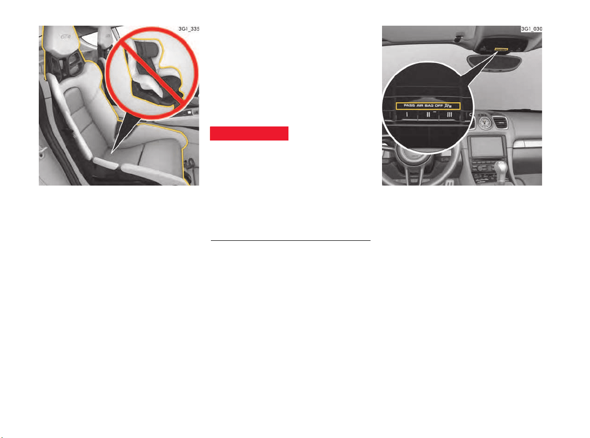
42 Seats, Mirrors and Steering Wheel
Full bucket seat
Installation of child restraint systems on
different seat variants
Child restraint systems must not be used on full
bucket seats (Illustration). The recommended
child seat systems may be used for all other seat
variants.
f Please see the chapter “CHILD RESTRAINT
SYSTEMS” on page 39.
f Please see the chapter “SEATS” on page 31.
Automatic locking retractor
The safety belt for the passenger seat is equipped
with an automatic locking retractor for securing
the child restraint system. When activated, this
retractor allows you to securely fasten the child
restraint system in place so that inadvertent
movements will not occur.
Before transporting a child on the passenger seat:
f Please see the chapter “CHILD RESTRAINT
SYSTEMS” on page 39.
f After fastening the child restraint system, do
not adjust the seat in any direction.
Moving the seat could adjust the safety belt
against the child restraint and cause the “PASS AIR
BAG OFF” indicator lamp to go off and activate the
airbag system.
f Check the condition of the passenger airbag
system shown by the indicator lamp in the
overhead operating console.
PASS AIR BAG OFF indicator lamp
Activating the automatic locking retractor
1. If a child restraint system must be fastened to
the passenger's seat, adjust the passenger's
seat as far away from the airbag as possible.
2. Position child seat according to the child seat’s
manufacturer instructions.
3. Pull the safety belt retractor completely out. At
this point the locking mechanism is activated.
4. Insert the safety belt tongue into the buckle
and make certain that it is properly latched.
Make no more adjustments to the seat.
5. Allow the safety belt to retract until it is tight on
the child restraint system. You may further
tighten the belt by pulling on it to allow more of
it to retract.
Make sure that excessive safety belt forces do
not occur by moving the seat with the child
seat installed.
Adjusting child seat
after fastening
DANGER
h
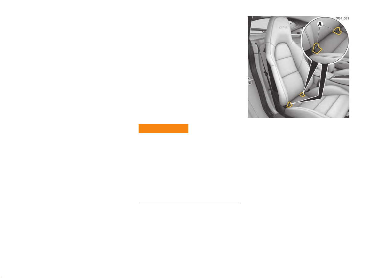
Seats, Mirrors and Steering Wheel 43
Releasing the safety belt
1. Unbuckle the safety belt latch.
2. Then make certain that the belt has fully
retracted. At this point the automatic locking
feature will be disengaged.
Seek appropriate advice from your authorized
Porsche dealer about the possible installation
of a Porsche child restraint system.
Top Tether
Top Tether child seats are the best option for
mounting a child seat in your Porsche.
Such Top Tether child seats can be installed only
using the Top Tether on the rear wall behind the
passenger seat.
Use only child restraint systems with Top Tether
recommended by Porsche.
These systems have been tested and adjusted to
the interior of your Porsche and the appropriate
child weight groups.
Other systems have not been tested and could
entail an increased risk of injury.
f To ensure proper installation, see your
authorized Porsche dealer
f Always observe the separate installation
instructions for your child seat.
Child restraint anchorages are designed to
withstand only those loads imposed by correctly
fitted child restraints. Under no circumstances are
they to be used for adults safety belts or
harnesses.
f Do not misuse the child restraint anchorages.
Only attach one child seat tether per
anchorage.
f They are not designed to withstand loads
imposed by adults.
f Please see the chapter “AUTOMATIC LOCKING
RETRACTOR” on page 42.
Installing a Top Tether child seat system
f Always observe the separate installation
instructions for your child seat.
1. Secure the child seat to retaining lugs A as
outlined in the operating manual for the child
seat.
2. Pull the child seat to check that both fastening
points are engaged correctly.
3. If the child restraint seat or seats require the
use of a tether strap, attach the tether strap to
the anchor point on the rear wall behind the
passenger seat and pull it tight (Illustration).
Misuse of Childseat
Restraint Anchorages
WARNING
h
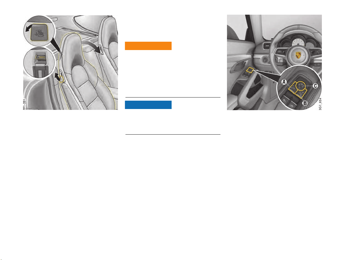
44 Seats, Mirrors and Steering Wheel
Upper anchorage point for child restraint
systems
When using a child r
estraint system with a top
tether, the anchorage point on the rear wall behind
the passenger seat is used to secure the top
tether.
Exterior Mirrors
The convex mirror on the passenger’s side and the
aspherical mirror on the driver’s side provide
a larger field of view.
Vehicles or objects appear smaller in convex
mirrors and further away than they are in reality.
f Bear this distortion in mind when estimating
the distance of vehicles behind you and when
reversing into a parking space.
f Also make use of the interior mirror for judging
distance.
Risk of damage to the exterior mirrors when
washing the vehicle in a car wash.
f Fold in exterior mirrors before using the car
wash.
A - Exterior mirror selection – driver’s side
B - Exterior mirror selection – passenger's side
C - Adjusting exterior mirrors
Adjusting exterior mirrors
The electrical exterior mirror adjuster is ready for
operation:
– With ignition switched on.
– After the ignition is switched off and before the
driver’s or passenger’s door is first opened,
but for a maximum of 10 minutes.
Judging distance in
convex side mirror
WARNING
h
NOTICE
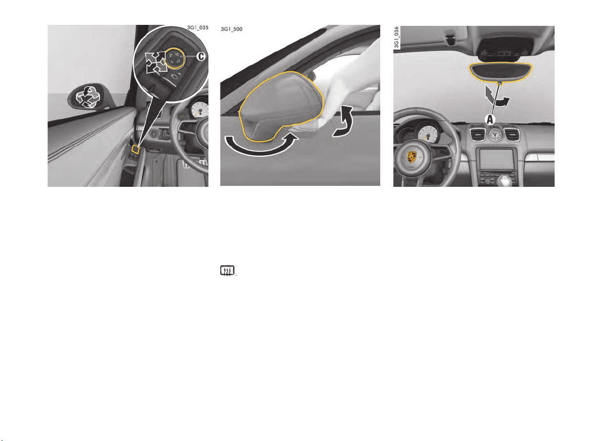
Seats, Mirrors and Steering Wheel 45
1. Press selection button A for the driver’s side
and selection button B for the passenger’s
side.
The indicator light on the pressed button
lights up.
2. Move the exterior mirrors to the correct
position by pressing the adjustment button C.
If the electrical adjustment facility fails
f Adjust the mirror by pressing on the mirror
face.
Folding in exterior mirrors manually
f Swivel the mirror housing diagonally upwards
by hand as far as it will go.
Folding out exterior mirrors manually
f Swivel the mirror housing diagonally
downwards by hand as far as it will go.
Exterior mirror heating
The exterior mirror heating is activated
automatically when the heated rear window is
switched on while the engine is running.
For information on switching on the heated rear
window:
f Please see the chapter “HEATED REAR
WINDOW/ EXTERIOR MIRROR HEATING”
on page 59.
If the charging condition of the battery is critical,
the exterior mirror heating function is restricted
initially and then switched off.
Interior Mirror
The interior mirror’s reflection is undistorted.
When the mirror is being adjusted, the anti-dazzle
lever A must point forwards.
f Normal position – lever forward.
f Anti-dazzle position – swivel lever back.
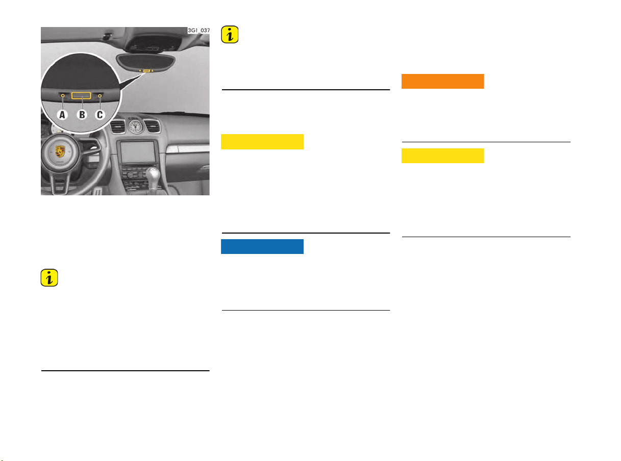
46 Seats, Mirrors and Steering Wheel
Automatic anti-dazzle interior mirror
Sensors on the front and rear sides of the interior
mirror measure the incident light. The mirror
automatically changes to anti-dazzle position or
reverts to its normal state, depending on the light
intensity.
Information
The incident light within the detection area of the
light sensor C must not be restricted (e.g. by
stickers on the rear window or items of luggage in
the luggage compartment or on the luggage
compartment cover). Likewise, the incident light
coming through the windscreen to the front light
sensor must not be restricted (e.g. by stickers).
Switching off automatic anti-dazzle function
f Press button B.
The indicator light A goes out.
Information
The anti-dazzle function switches off
automatically if:
– Reverse gear is engaged or
– Interior lighting is switched on.
Switching on automatic anti-dazzle function
f Press button B.
The indicator light A lights up.
Electrolyte fluid may escape from broken mirror
glass. This fluid irritates the skin and eyes.
f If the electrolyte fluid should come into contact
with the skin or eyes, rinse it off immediately
with clean water.
Seek medical attention if necessary.
Risk of damage to paintwork, leather, plastic
parts and clothing.
Electrolyte fluid can be removed only while it is
still wet.
f Clean the effected parts with water.
Automatic anti-dazzle exterior mirror
The exterior mirrors change to anti-dazzle position
automatically in synchronization with the interior
mirror.
Steering Wheel Adjustment
The steering wheel can be adjusted manually or
electrically in four directions depending on the
vehicle equipment.
The steering wheel may move further than desired
if you attempt to adjust it when driving.
You may lose control of the vehicle.
f Do not adjust the steering wheel when driving.
If persons or animals are in the movement range
of the steering wheel during adjustment or if the
person buttons are pressed unintentionally when
the vehicle is at a standstill, parts of the body
could get trapped or crushed.
f Do not leave children in the vehicle unattended.
Electrolyte fluid may
escape if the mirror
glass is broken
CAUTION
h
NOTICE
Steering wheel
adjustment while driving
Memory steering wheel
movement
WARNING
h
CAUTION
h
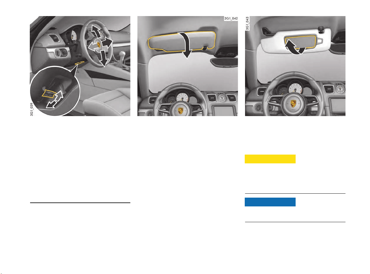
Seats, Mirrors and Steering Wheel 47
Manual steering wheel adjustment
Adjusting steering wheel manually
1. Insert the ignition key fully into the ignition lock.
2. Push locking lever downwards.
3. Adjust steering wheel to suit the chosen
backrest angle and your seat position by
moving the steering wheel up or down and
longitudinally.
4. Swivel locking lever back until you feel it
engage.
If necessary, move the steering wheel slightly
in a longitudinal direction.
Sun Visors
f Swivel the sun visor down to prevent dazzle
from the front.
f If you are dazzled from the side, unclip the sun
visor from the inner bracket and swivel it round
so that it is in front of the door window.
Vanity Mirror
The vanity mirror on the rear of the sun visor is
closed with a cover.
The vanity mirror illumination is switched on
automatically when the cover is opened.
The mirror glass may break in the event of an
accident and may enter the passenger
compartment if the cover is open.
f Keep the cover closed when driving.
Risk of damage to the vanity mirror cover.
f Do not force the cover beyond its end position.
Cover of vanity mirror
open
CAUTION
h
NOTICE

48 Air Conditioning
Air Conditioning
Heating and Ventilation..................................49
Manual Air Conditioning .................................51
Automatically Controlled
2-zone Air Conditioning..................................54
Air Vents ......................................................59
Heated Rear Window/Exterior Mirror Heating ..59
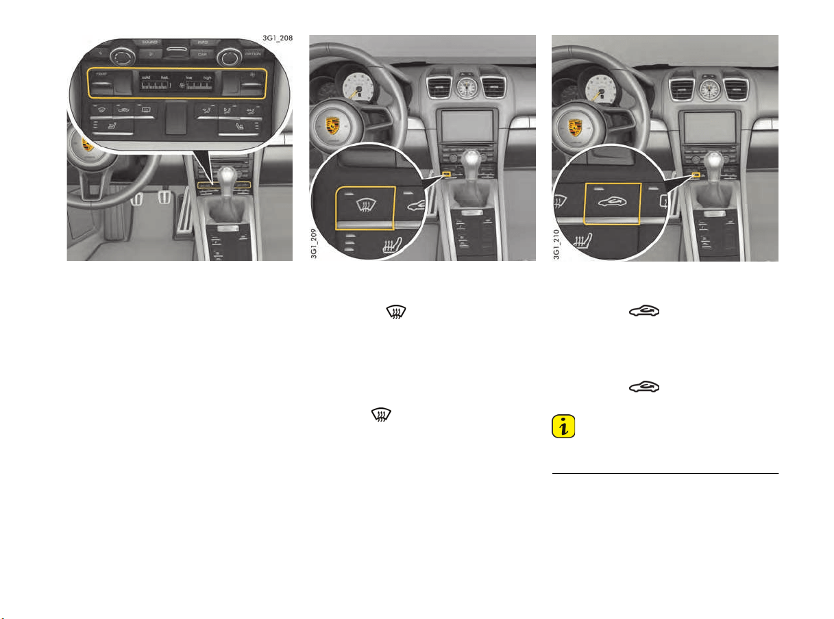
Air Conditioning 49
Heating and Ventilation
Air quantity, air distribution and temperature can
be set on the control panel.
Defrosting windshield
Activating defrosting function
f Press button .
The indicator light on the button lights up.
The air flows to the windshield and the front
side windows.
The windshield is demisted or defrosted as
quickly as possible.
Deactivating defrosting function
f Press the button.
The indicator light on the button goes out.
Air-recirculation mode
Switching on air-recirculation mode
f Press button .
The indicator light on the button lights up.
The outside-air supply is interrupted and only
the inside air is recirculated.
Switching off air-recirculation mode
f Press button .
The indicator light on the button goes out.
Information
Air-recirculation mode ends automatically after
approx. 3 minutes.
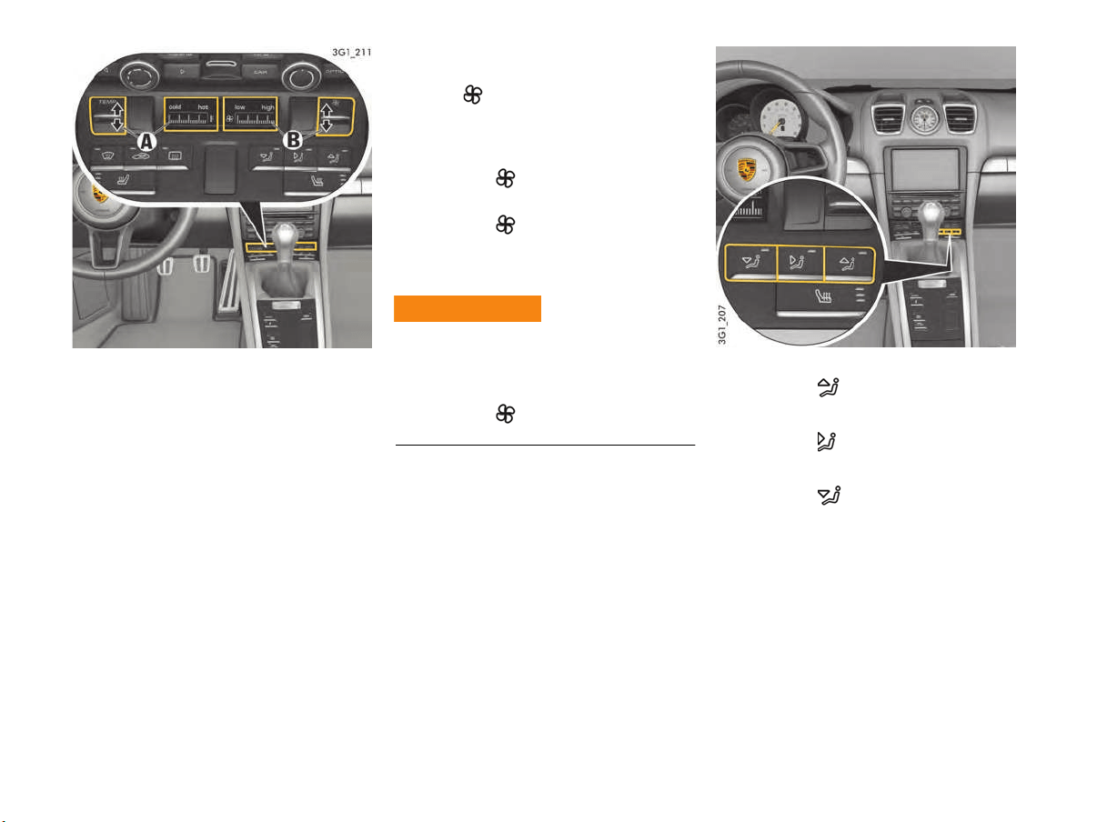
50 Air Conditioning
A - Set temperature
B - Set air quantity
Setting temperature
The selected temperature is shown on the display
by a bar display.
Increasing temperature
f Press button TEMP upwards.
If all bars can be seen, the temperature is set
to maximum heat (hot).
Reducing temperature
f Press button TEMP downwards.
If no bars can be seen, the temperature is set
to maximum coldness (cold).
Setting air quantity
The selected air quantity is shown in a bar display
next to the symbol. The more bars that are
displayed, the more air flows into the passenger
compartment.
Increasing air quantity
f Press button upwards.
Reducing air quantity
f Press button downwards.
If the air quantity was reduced so much that OFF
appears on the control panel display, the supply of
air from the outside is interrupted.
The windows can mist up if the air quantity setting
is OFF.
f Only select air quantity setting OFF for short
periods.
f Press button upwards (increase air
quantity).
Setting air distribution
f Press button .
The air flows to the windshield and the side
windows.
f Press button .
The air flows from the central and side vents.
The air vents must be open.
f Press button .
The air flows to the footwell.
The indicator light on the button lights up.
Air Shut-off Impairing
Vision
WARNING
h
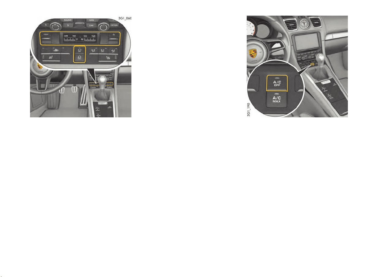
Air Conditioning 51
Manual Air Conditioning
The air quantity, air distribution and temperature
can be set manually on the manual air-conditioning
system in order to influence the interior climate.
Information on air-conditioning
compressor
The air-conditioning compressor
– Can switch off briefly to ensure sufficient
engine cooling if the engine is operating under
extreme load.
– Automatically switches off at temperatures
below approx. 36 °F (2 °C) and cannot be
switched on, even manually.
– Operates most effectively with the windows
closed.
If the vehicle has been in the sun for a long
time, it is a good idea to ventilate the interior
briefly with the windows open.
– Depending on the outside temperature and
humidity, condensation can drip from the
evaporator and form a pool under the vehicle.
This is normal and not a sign of leakage.
Information on automatic load switch-off
If the charging condition of the battery is critical,
the following air-conditioning or heating functions
are restricted initially and then switched off:
– Seat heating
– Seat ventilation
– Heated rear window/Exterior mirror heating
– Fresh-air blower
– Air-conditioning compressor
A/C mode
At outside temperatures above approx.
36 °F (2 °C), the air-conditioning compressor can
be switched on or off manually.
The air-conditioning compressor is switched off
automatically at outside temperatures below
approx. 36 °F (2 °C).
Switching A/C mode on
If you wish to cool the passenger compartment to
a temperature lower than the outside
temperature, A/C mode must be activated.
f Press button A/C OFF.
The indicator light on the button goes out.
The air-conditioning compressor is switched
on.
The cooling function is activated.
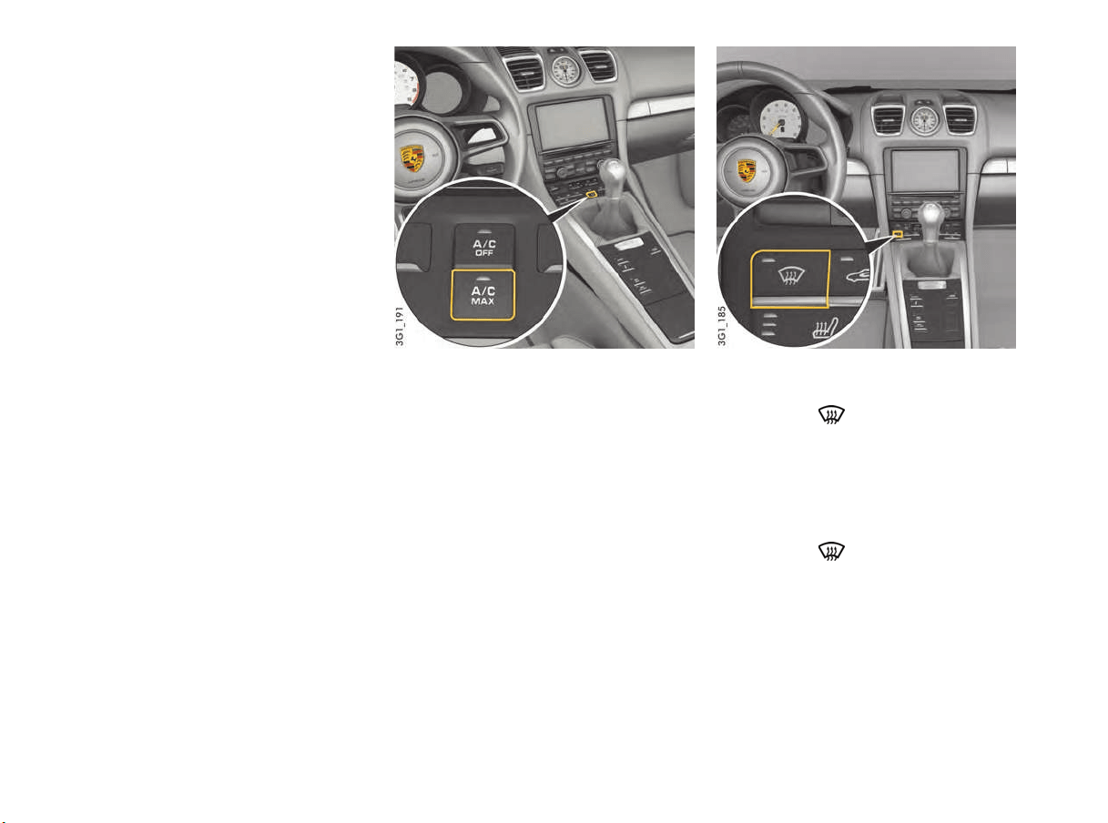
52 Air Conditioning
Switching A/C mode off
A/C mode can be switched of
f manually to save
fuel, for example.
f Press button A/C OFF.
The indicator light on the button lights up.
The air-conditioning compressor is switched
off.
The cooling function is deactivated.
A/C MAX mode
In A/C MAX mode, the passenger compartment is
cooled at maximum power.
Switching A/C MAX mode on
f Press button A/C MAX.
The indicator light on the button lights up.
Switching A/C MAX mode off
f Press button A/C MAX.
The indicator light on the button goes out.
Defrosting windshield
Activating defrosting function
f Press button .
The indicator light on the button lights up.
The air flows to the windshield and the side
windows.
The windshield is demisted or defrosted as
quickly as possible.
Deactivating defrosting function
f Press button .
The indicator light on the button goes out.
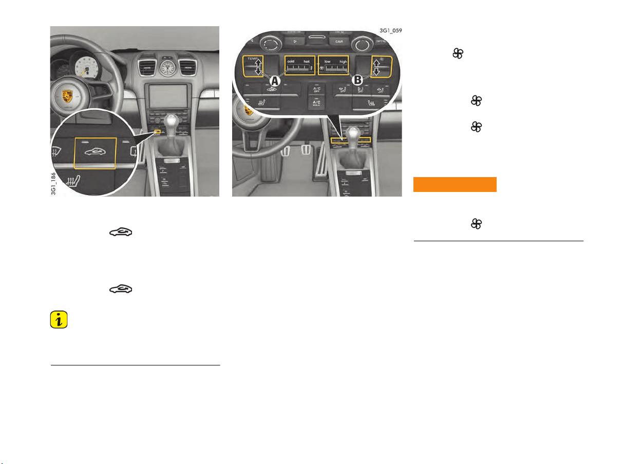
Air Conditioning 53
Circulating-air mode
Switching on air-recirculation mode
f Press button .
The indicator light on the button lights up.
The outside-air supply is interrupted and only
the inside air is recirculated.
Switching air-recirculation mode off
f Press button .
The indicator light on the button goes out.
Information
If the air-conditioning compressor is switched off
manually or automatically, air-recirculation mode
ends automatically after approx. 3 minutes.
A - Set temperature
B - Set air quantity
Setting temperature
The selected temperature is shown on the display
by a bar display.
Increasing temperature
f Press button TEMP upwards.
If all bars can be seen, the temperature is set
to maximum heat (hot).
Reducing temperature
f Press button TEMP downwards.
If no bars can be seen, the temperature is set
to maximum coldness (cold).
Setting air quantity
The selected air quantity is shown in a bar display
next to the symbol. The more bars that are
displayed, the more air flows into the passenger
compartment.
Increasing air quantity
f Press button upwards.
Reducing air quantity
f Press button downwards.
If the air quantity was reduced so much that
OFF appears on the air-conditioning display,
the outside-air supply is interrupted and
the air-conditioning compressor is switched off.
The windows can mist up if the air quantity setting
is OFF.
f Press button upwards (increase air
quantity).
Impaired vision with air
quantity OFF
WARNING
h
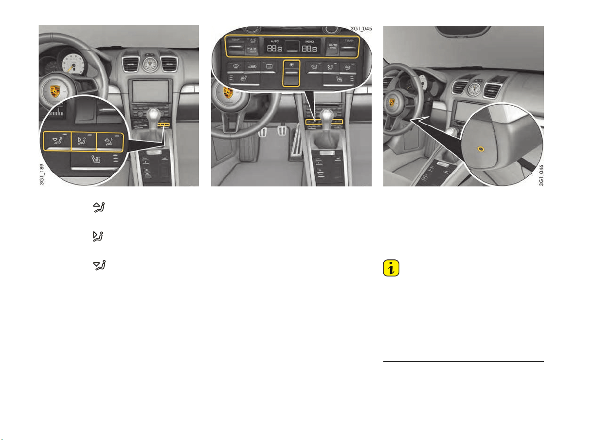
54 Air Conditioning
Setting air distribution manually
f Press button .
The air flows to the windshield and the side
windows.
f Press button .
The air flows from the central and side vents.
The air vents must be open.
f Press button .
The air flows to the footwell.
The indicator light on the button lights up.
Automatically Controlled 2-zone
Air Conditioning
The temperature can be set individually for the
driver’s and passenger’s side.
In automatic mode the air conditioning system
exercises full control over the air temperature, air
distribution, and air quantity. A number of factors
(such as ambient air temperature, amount of
sunlight, etc...) are used by the system to
determine the optimum settings for the current
situation.
Automatic mode is deactivated as soon as the
settings are adjusted manually. In this case,
automatic climate control still regulates the
air-conditioning functions that have not been
modified manually.
Interior temperature sensor
Sensors
To avoid impairing the function of the air
conditioning system, the interior temperature
sensor for the air-conditioning system must not
be covered or taped over.
Information
Additional air conditioning settings can be made
on the multi-function display on the instrument
panel:
f Please see the chapter “SETTING AIR
CONDITIONING” on page 104.
All air-conditioning system settings are stored on
the respective vehicle key when the vehicle is
locked, on vehicles with memory.
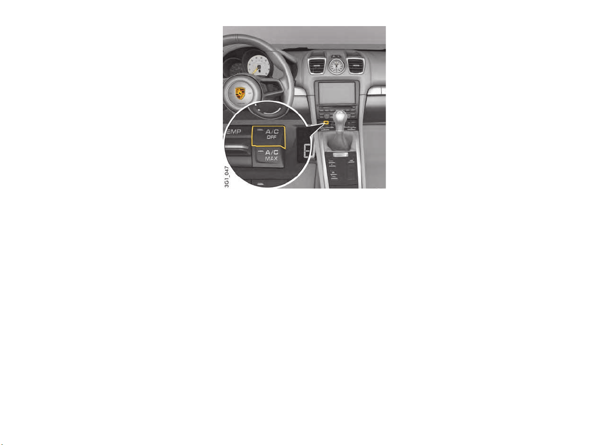
Air Conditioning 55
Information on air-conditioning
compressor
The air-conditioning compressor
– Can switch off briefly to ensure sufficient
engine cooling if the engine is operating under
extreme load.
– Switches off automatically at temperatures
below approx. 36 °F (2 °C) and cannot be
switched on, even manually.
– Operates most effectively with the windows
closed.
If the vehicle has been in the sun for a long
time, it is a good idea to ventilate the interior
briefly with the windows open.
– Depending on the outside temperature and
humidity, condensation can drip from the
evaporator and form a pool under the vehicle.
This is normal and not a sign of leakage.
Information on automatic load switch-off
If the charging condition of the battery is critical,
the following air-conditioning or heating functions
are restricted initially and then switched off:
– Seat heating
– Seat ventilation
– Heated rear window/Exterior mirror heating
– Fresh-air blower
– Air-conditioning compressor
A/C mode
In automatic mode, A/C mode is activated by
default.
The power for the air conditioning compressor is
fully controlled by the air conditioning system
depending on the current operating requirements.
The air-conditioning compressor is switched off
automatically at outside temperatures of less
than approx. 36 °F (2 °C).
Switching A/C mode on
If you wish to cool the passenger compartment
to a temperature lower than the outside
temperature, A/C mode must be activated.
f Press button A/C OFF.
The indicator light on the button goes out.
The air-conditioning compressor is
switched on.
or
Press button AUTO/SYNC.
The cooling function is activated.
Switching A/C mode off
A/C mode can be switched off manually to save
fuel, for example.
f Press button A/C OFF.
The indicator light on the button lights up.
The air-conditioning compressor is
switched off.
The cooling function is deactivated.
SYNC mode
In SYNC mode, the temperatures on the driver’s
and passenger’s side are synchronized and are
regulated via button TEMP on the driver’s side.
Switching on SYNC mode
f Press button AUTO/SYNC and hold until
SYNC appears on the display.
f Regulate the temperature on the driver’s and
passenger’s side via button TEMP on the
driver’s side.
Switching off SYNC mode
f Press button AUTO/SYNC or button TEMP
on the passenger’s side.
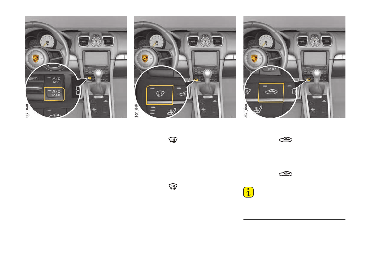
56 Air Conditioning
A/C MAX mode
In A/C MAX mode, the passenger compartment
is cooled at maximum power.
The interior temperature is not regulated
automatically.
If the vehicle has been in the sun for a long
time, it is a good idea to ventilate the interior
briefly with the windows open.
Switching A/C MAX mode on
f Press button A/C MAX.
The indicator light on the button lights up.
Switching A/C MAX mode off
f Press button A/C MAX.
The indicator light on the button goes out.
or
Press button AUTO/SYNC.
Defrosting windshield
Activating defrosting function
f Press button .
The indicator light on the button lights up.
The air flows to the windshield and the front
side windows.
The windshield is demisted or defrosted as
quickly as possible.
Deactivating defrosting function
f Press button .
The indicator light on the button goes out.
or
Press button AUTO/SYNC.
Air-recirculation mode
Switching on air-recirculation mode
f Press button .
The indicator light on the button lights up.
The outside-air supply is interrupted and only
the inside air is recirculated.
Switching air-recirculation mode off
f Press button .
The indicator light on the button goes out.
Information
If the air-conditioning compressor is switched off
manually or automatically, recirculated air mode
ends after approx. 3 minutes.
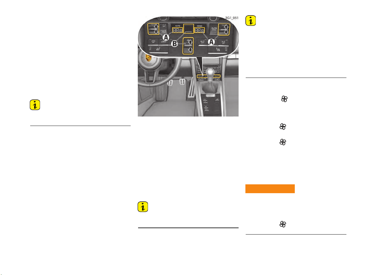
Air Conditioning 57
Setting automatic air-recirculation mode
In automatic air-recirculation mode, the fresh air
supply is adjusted depending on the air quality.
Automatic air-recirculation mode can be switched
on and off on the multi-function display.
Air-recirculation mode is deactivated automatically
to prevent the windows from misting at outside
temperatures of less than approx. 41 °F (5 °C).
For information on adjusting automatic
air-recirculation mode on the multi-function
display:
f Please see the chapter “SETTING AIR
CONDITIONING” on page 104.
Information
The recommended operating mode is automatic
air-recirculation mode (default setting).
A - Set temperature left/right
B - Set air quantity
Setting temperature
For personal comfort, the interior temperature
can be adjusted individually for the driver’s and
passenger’s side between 61 °F (16 °C) and
85 °F (29.5 °C). Recommendation: 72 °F (22 °C).
The selected temperature is shown on the display.
Increasing temperature
f Press button TEMP upwards.
The preset temperature value is shown on
the air-conditioning display.
Information
Pressing button AUTO/SYNC selects the preset
temperature.
Information
The air-conditioning system always cools and
heats the passenger compartment to the preset
temperature at maximum cooling or heating
temperature.
Setting the temperature temporarily to a lower or
higher value does not cool or heat the passenger
compartment to the desired temperature more
quickly.
Set air quantity
The selected air quantity is shown in a bar display
above the button . The more bars that are
displayed, the more air flows into the passenger
compartment.
Increasing air quantity
f Press button upwards.
Reducing air quantity
f Press button downwards.
Pressing button AUTO/SYNC switches back to
automatic mode.
If the air quantity was reduced so much that OFF
appears on the air-conditioning display, the
outside-air supply is interrupted and the air-
conditioning compressor is switched off.
The windows can mist up if the air quantity setting
is OFF.
f Only select air quantity setting OFF for short
periods.
f Press button upwards (increase air
quantity).
Air shut-off impairing
vision
WARNING
h
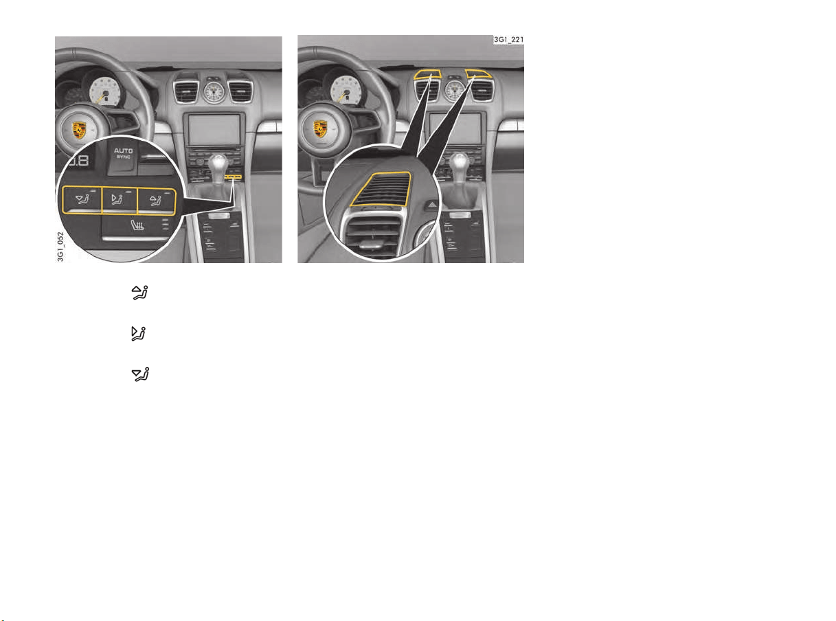
58 Air Conditioning
Setting air distribution manually
f Press button .
The air flows to the windshield and the side
windows.
f Press button .
The air flows from the central and side vents.
The air vents must be open.
f Press button .
The air flows to the footwell.
The indicator light on the button lights up.
Cancelling manual air distribution
f Press the relevant air distribution button again.
The indicator light on the button goes out.
or
Press button AUTO/SYNC.
Air quantity and distribution are controlled
automatically and variations are compensated.
Extended ventilation panel
With the automatically controlled 2-zone
airconditioning system, the extended ventilation
panel on top of the dashboard can be activated or
deactivated separately in the multi-function display
on the instrument panel.
The air flow in the passenger compartment is less
direct.
The automatic control of the air-conditioning
system adjusts the air flow quantity automatically.
Air-conditioning settings on the
multi-function display
With the automatically controlled 2-zone
airconditioning system, additional settings relating
to vehicle air conditioning can be adjusted in the
multi-function display on the instrument panel.
For information on air-conditioning settings on
the multi-function display:
f PLEASE SEE THE CHAPTER “SETTING AIR
CONDITIONING” on page 104.
Air flow
Three air flow settings are available in automatic
mode:
–“Soft”:
Recommended for passengers sensitive to
draughts with a preference for gentle air
conditioning.
–“Normal”:
Default setting.
–“Strong”:
Stronger ventilation in the passenger
compartment.
The air flow is clearly noticeable.
Auto air-recirculation mode
f Auto air-recirculation mode can be switched
on and off.
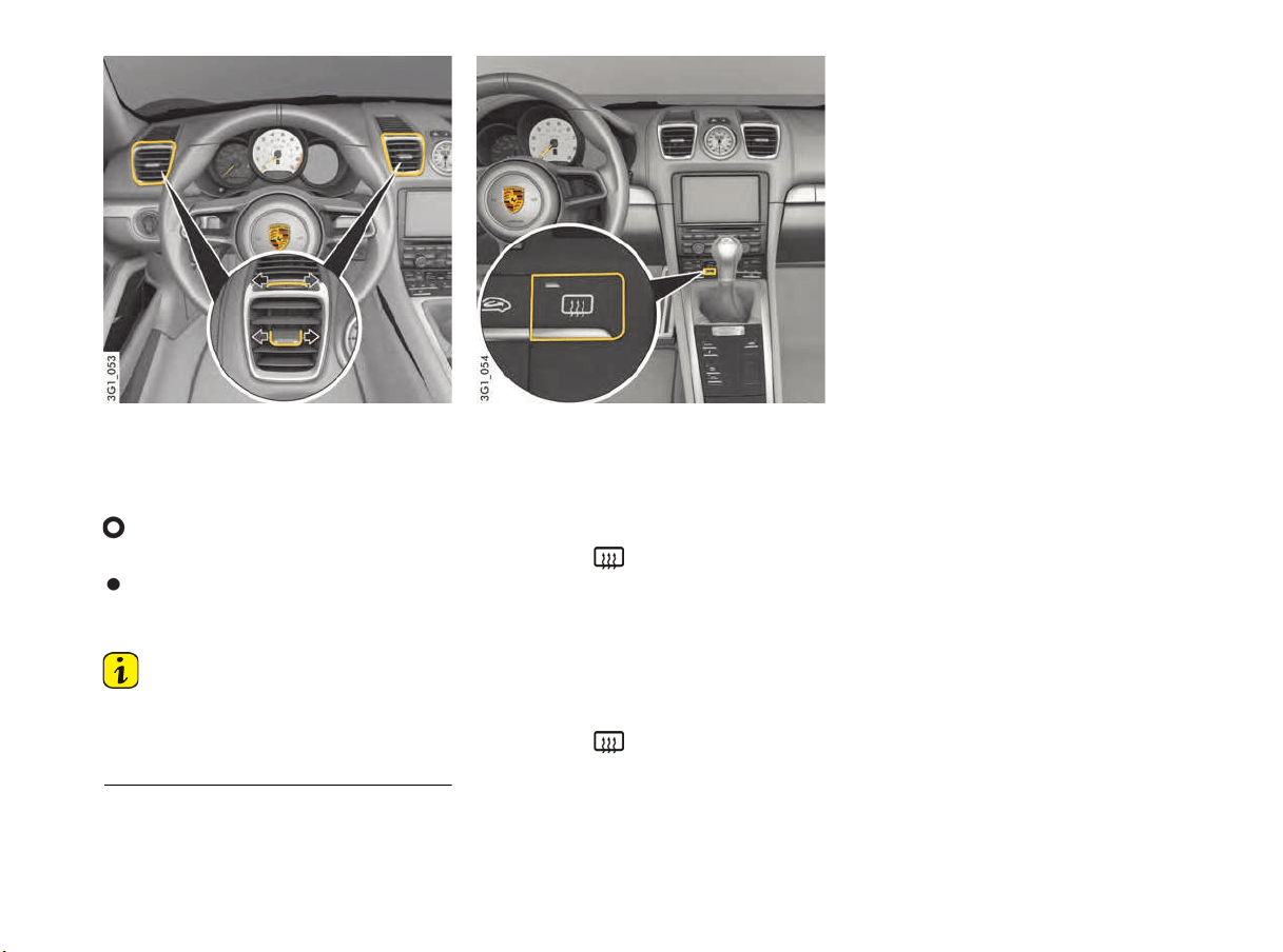
Air Conditioning 59
Air Vents
Air vents are located on the dashboard that can be
opened and closed manually. The direction of the
air flow can also be adjusted.
Opening vents
f Turn the thumb wheel on the air vent upwards.
Closing vents
f Turn the thumb wheel on the air vent
downwards.
Information
f For optimal air conditioning, we recommend
keeping the center air vents closed during the
cold season and to only open them as required
for the purpose of warming the hands.
Changing air flow direction
f Swivel vent vanes in the desired direction.
Heated Rear Window/
Exterior Mirror Heating
Heated rear window/exterior mirror heating is
ready for operation when the engine is running.
Switching on
f Press button .
The indicator light on the button lights up.
Depending on the outside temperature,
the heating switches off automatically after
approx. 5 to 20 minutes.
f The heating can be switched back on by
pressing the button again.
Switching off
f Press button .
The indicator light on the button goes out.
If the charging condition of the battery is critical,
the heated rear window/exterior mirror heating
function is restricted initially and then switched off.

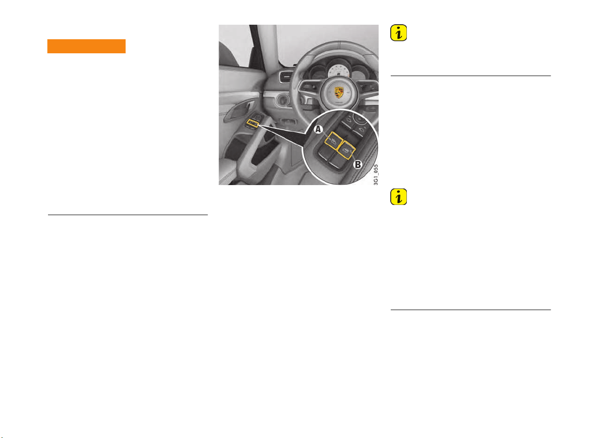
Windows 61
Power Windows
When opening or closing the windows, particularly
in one-touch mode, parts of the body may get
trapped between the moving window and fixed
vehicle parts.
f Take care to ensure that nobody can be injured
when the windows open or close.
f Always remove the ignition key when leaving
the vehicle or switch off the ignition on vehicles
with Porsche Entry & Drive. Always take the
ignition key with you when leaving the vehicle.
Uninformed persons could injure themselves
by operating the power windows.
f
In case of danger, immediately release the button
on the ignition key or the button in the door
handle on vehicles with Porsche Entry & Drive.
f Do not leave children in the vehicle unattended.
Readiness for operation of power windows
The power windows are ready for operation:
– With ignition switched on.
– After the ignition is switched off and before the
driver’s or passenger's door is first opened,
but for a maximum of 10 minutes.
One-touch operation for closing the door
windows is available only when the ignition is
switched on.
A - Power window, driver’s side
B - Power window, passenger’s side
Opening/closing windows
Opening window with the switch
f Press the relevant switch until the window
has reached the desired position.
Closing window with the switch
f Pull the relevant switch until the window has
reached the desired position.
Information
The switches have a two-stage function. Both
detent positions can be felt clearly when you
actuate the switch.
– First setting – manual operation
If the relevant switch is moved to the first
position, the window is opened or closed
manually.
The window stops when the switch is released.
– Second setting – one-touch operation
If the relevant switch is moved fully to the
second position, the window is opened or
closed automatically.
Actuate the switch again to stop the window at
the desired position.
Information
If a door window is blocked during closing, it will
stop and open again by several centimetres.
If the window is blocked a second time within
approx. 10 seconds, one-touch operation is
disabled for this window.
The window can be closed manually. The window
then closes with its full closing force.
One-touch operation is enabled again once the
window has been closed completely using the
manual closing function.
Opening and closing the
windows
WARNING
h

62 Windows
If one-touch operation is disabled after the window
is blocked, the window will close with its full
closing for
ce when the manual closing function is
used.
f Ensure that nobody can be injured, pinched or
crushed when the windows close.
Storing end position of the windows after
connecting the vehicle battery
The end positions of the windows are lost when
the battery is disconnected and reconnected.
One-touch operation of the windows is disabled.
Perform these steps for all windows:
1. Close window completely once by pulling the
rocker switch.
2. When the window is completely closed, briefly
pull the rocker switch again three times.
3. Open the window completely once by pressing
the rocker switch.
Closing the windows
manually
WARNING
h

Lights, Turn Signals and Windshield Wipers 63
Lights, Turn Signals and Windshield Wipers
Light Switch..................................................64
Instrument Lighting .......................................66
Turn Signal/High Beam/Headlight
Flasher Stalk/Parking Light Switch..................66
Emergency Flasher .......................................67
Interior/Reading Lights ..................................67
Brief Overview – Windshield wipers ..............69
Windshield Wiper/Washer Stalk ......................70
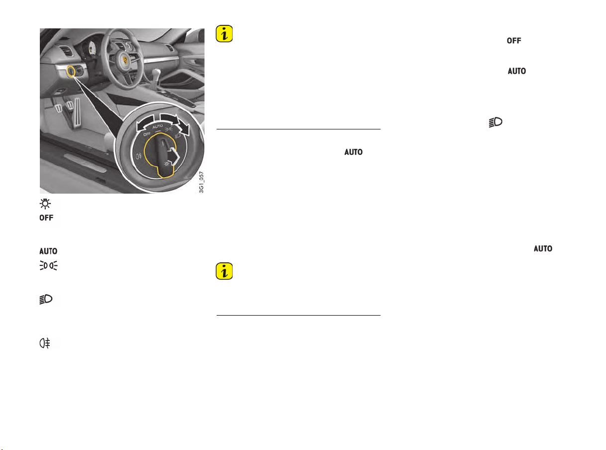
64 Lights, Turn Signals and Windshield Wipers
Information
If the ignition key is r
emoved and the door is
opened while the lights are on, an audible signal
(gong) warns of possible battery discharge.
– In some countries, differences are possible
due to legal requirements.
The vehicle’s exterior lights can mist up due to
temperature and humidity. This misting will dry off
after a sufficient distance has been driven.
Low beam/driving light
If the light switch is set to the position ,
the low beam is switched on automatically in the
following situations:
– Dusk
– Darkness
– Driving through tunnels
– Rain
– Highway driving (on vehicles with
Porsche Dynamic Light System PDLS)
When the low beam is switched on, the indicator
light on the speedometer lights up.
Information
Fog is not automatically recognized.
f In the event of fog, the driving light must be
switched on manually.
Highway function in daylight
The driving light switches on automatically at
speeds of more than approx. 140 km/h (90 mph)
in bright conditions and when the daytime running
lights are deactivated. When driving at a speed of
less than approx. 65 km/h (40 mph), the driving
light is switched off after a delay of approx. 4 min.,
provided the external lighting conditions permit.
Daytime driving lights
If the light switch is set to position (light off),
the daytime driving lights come on automatically
when the ignition is switched on.
If the light switch is set to position , the
daytime driving lights come on automatically in
bright conditions and when the ignition is switched
on.
The daytime driving lights are not active when the
light switch is set to position (low beam/
driving light).
Automatic driving light assistant
The automatic driving light assistant is a comfort
function. The driving light (low beam) is switched
on and off automatically depending on the ambient
brightness.
The automatic driving light assistant also controls
the daytime driving lights, low beam, Automatic
Coming Home lights and the equipment-
dependent dynamic cornering light.
The automatic driving light assistant is activated
when the light switch is set to the position .
Despite possible support by the driving light
assistant, it is the responsibility of the driver to
switch on the driving light using the conventional
light switch in accordance with the relevant
national regulations.
Activating the headlights using the driving light
assistant therefore does not absolve the driver
of responsibility for correct operation of the
driving light.
Light Switch
Light is switched off
Daytime driving lights are switched on
when the ignition is switched on.
Automatic driving light assistant
Side lights
License plate light, instrument lighting,
daytime driving lights switched off.
Low beam/driving light
Only with ignition on.
Fog light function and highway light are
switched off.
Rear fog light
Pull the switch in the low beam position.
Indicator light lights up.

Lights, Turn Signals and Windshield Wipers 65
If you drive without lights, this may significantly
restrict your visibility and also the ability of other
road users to see your vehicle.
f Always carefully monitor the automatic driving
light control.
Information
In the event of a fault in the automatic driving light
assistant/Porsche Dynamic Light System (PDLS),
the PDLS warning light in the instrument panel
flashes.
For information on indicator lights and warning
lights on the instrument panel:
f Please see the chapter “INSTRUMENT PANEL
USA MODELS” on page 74.
f Please see the chapter “OVERVIEW OF
WARNING AND INFORMATION MESSAGES”
on page 109.
Rain function
The driving light is switched on automatically after
five seconds of continuous wiper operation.
If the wipers have not been used for approx.
4 minutes, the driving light is switched off.
Automatic Coming Home lights
(Welcome Home function/Entry function)
Switching on Automatic Coming Home lights
f Set light switch to .
The following lights remain switched on for
a certain period to allow you to get in and out of
your vehicle safely and with improved visibility in
darkness:
– Daytime driving lights,
– Courtesy lights in the folded out exterior
mirrors (on vehicles with electrically foldable
mirrors),
– Rear side marker lights,
– License plate lights.
Welcome Home function (off delay)
When the vehicle is locked, the lights remain
switched on for the duration of the off delay preset
on the multi-function display.
For information on adjusting the off delay of the
external lights on the multi-function display:
f Please see the chapter “ADJUSTING EXTERIOR
LIGHTS” on page 102.
Entry function/Exit function
When the vehicle is unlocked, the area around
the vehicle is illuminated for the duration of the
off delay preset on the multi-function display.
The lights are switched off when the ignition is
switched on or the light switch is set to a position
other than .
For information on adjusting the off delay of the
external lights on the multi-function display:
f PLEASE SEE THE CHAPTER “ADJUSTING
EXTERIOR LIGHTS” on page 102.
Porsche Dynamic Light System (PDLS)
The dynamic cornering light as well as the highway
function in darkness are activated when the light
switch is set to the position
.
Dynamic cornering light
Above a speed of approx. 5 mph (8 km/h), the low
beam light is swiveled in the direction of the curve
to illuminate the road more clearly, depending on
the speed of the vehicle and the extent to which
the steering wheel is turned.
In the event of a fault in the dynamic cornering
light, the PDLS warning light in the instrument
panel flashes.
Highway function in darkness
The distribution characteristics of the driving light
change when driving in darkness at vehicle
speeds above approx. 80 mph (130 km/h).
The light beam becomes longer and the field of
vision increases.
Fog lights
The distribution characteristics of the driving light
change when the rear fog light is switched on at
vehicle speeds below approx. 43 mph (70 km/h).
The light beam becomes wider and reduces glare.
Driving without lights
WARNING
h
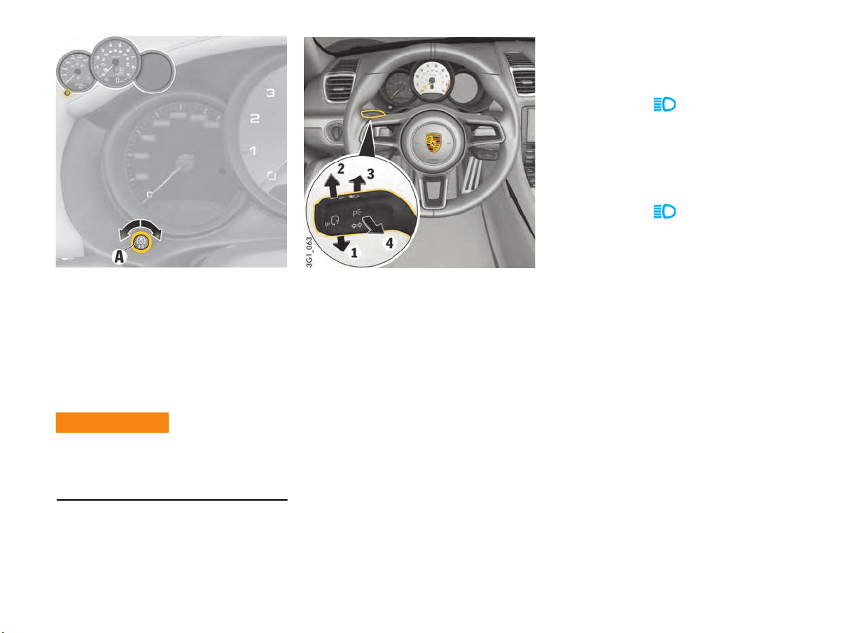
66 Lights, Turn Signals and Windshield Wipers
Instrument Lighting
The lighting is automatically adjusted to the
ambient brightness via light sensors.
In addition, when the vehicle lighting is switched
on, the instrument and switch brightness can be
adjusted manually.
f Turn adjustment button A in the appropriate
direction and hold until the desired brightness
has been reached.
Adjusting the brightness while driving may cause
you to lose control of the vehicle.
f Do not reach through the steering-wheel
spokes while driving.
Turn Signal/High Beam/Headlight
Flasher Stalk/Parking Light Switch
Turn signals, low beam and high beam are ready
for operation when the ignition is on.
1 – Turn signal light, left
2 – Turn signal light, right
3 – High beam
4 – Headlight flasher
Stalk in center position – low beam
Operating the turn signal light
f Push the stalk past the lower or upper
pressure point 1 or 2.
The turn signal lights stay on until the stalk is
moved back to its initial position either
manually or automatically as a result of turning
the steering wheel.
f Push the stalk once to the lower or upper
pressure point 1 or 2.
The turn signal lights flash three times.
High-beam headlight
Switching on and off
f Switching on: Push the stalk once to the front
pressure point 3.
The indicator light lights up on the
tachometer.
f Switching off: Push the stalk once to the rear
pressure point 4.
Operating the headlight flasher
f Push the stalk once to the rear pressure
point 4.
The indicator light on the tachometer
lights up briefly.
Parking light
The parking light can only be switched on when
the ignition is switched off.
f Move the stalk up 2 or down 1 to switch on the
right or left parking light.
If the parking light is switched on, the message
“Parking light on” will appear on the multi-
function display in the instrument panel after the
ignition is switched off.
For information on warning messages on the multi-
function display:
f Please see the chapter “OVERVIEW OF
WARNING AND INFORMATION MESSAGES”
on page 109.
Adjusting the brightness
while driving
WARNING
h
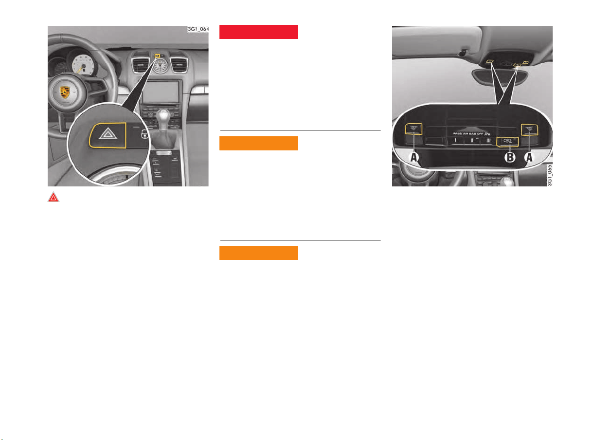
Lights, Turn Signals and Windshield Wipers 67
Emergency Flasher
The emergency flasher can be switched on
regardless of the position of the ignition lock.
Switching on and off
f Press the emergency flasher button on the
dashboard.
All turn signal lights and the indicator light in the
button flash when the button is operated.
If the emergency flasher remains active for longer
periods, the illumination phase of the flashing
interval is shortened to preserve the lights.
Other vehicles could collide with your vehicle if you
are parked in a dangerous position.
f Whenever stalled or stopped for emergency
repairs, move the car well off the road. Switch
on the emergency flasher and mark the car
with road flares or other warning devices.
f Do not remain in the car. Someone
approaching from the rear may not realize your
vehicle is stopped and cause a collision.
Exhaust fumes and the exhaust system are very
hot when the engine is running. The exhaust
system (including the tailpipe) remains hot for
some time after the vehicle is turned off.
f Do not park or operate the vehicle in areas
where the hot exhaust system may come in
contact with dry grass, brush, fuel spill or
other flammable material.
The engine and surrounding components become
very hot when the engine is running.
f Before working on any part in the engine
compartment, turn the engine off and let it cool
down sufficiently.
A - Button for interior/reading lights
B - Switching automatic interior/reading lights on/off
Interior/Reading Lights
Interior/reading lights
Switching interior/reading lights on and off
f Press button A.
Dimming (brightness adjustment)
f Press button A for at least 1 second and hold
until the desired level of brightness is
achieved.
Emergency stopping
Hot exhaust system and
tailpipe
Engine heat danger
when working
DANGER
h
WARNING
h
WARNING
h

68 Lights, Turn Signals and Windshield Wipers
Switching automatic interior/
reading lights on and off
Depending on equipment, the interior/reading
lights can be switched on and off using button B
or in the multi-function display menu.
Using button “B“:
f Press button B.
When automatic interior/reading lights are
switched off, the indicator light in the button
lights up.
When the automatic interior lighting is switched
on in darkness, the interior lighting is
– switched on: when a door is unlocked or
opened, or when the ignition key is removed
from the ignition lock.
– switched off: when both doors have been
closed, after a delay of approx. 120 seconds.
The off delay time can be preset on the multi-
function display.
The interior lighting goes out as soon as the
ignition is switched on or the vehicle is locked.
f Please see the chapter “SETTING INTERIOR
LIGHTING OFF DELAY” on page 103.
In the multi-function display menu:
On the multi-function display, you can set whether
the interior/reading lights should be switched on
or remain switched off when a door is unlocked or
opened or when the ignition key is removed from
the ignition lock:
f Please see the chapter “ACTIVATING OR
DEACTIVATING INTERIOR LIGHTS WHEN THE
DOOR IS OPENED (DEPENDING ON
EQUIPMENT)” on page 103.
The off delay for the interior/reading lights when
both doors are closed can be set on the
multifunction display:
f Please see the chapter “SETTING INTERIOR
LIGHTING OFF DELAY” on page 103.
Switching off of interior/reading lights to
protect the battery
In darkness, the interior lighting is switched off
16 minutes after the engine stops to preserve
the vehicle battery.
In daylight conditions, interior lights that were
switched on manually are switched off
automatically after 1 minute.
Orientation lighting
Lights in the overhead operating console and at
the ignition lock help vehicle occupants to locate
important controls in the vehicle in darkness and
ensure better overall orientation. The lights are
switched on when the vehicle is unlocked and
switched off again automatically when the vehicle
is locked.
Dimming (brightness adjustment)
The brightness of the orientation lighting is
adjusted on the multi-function display.
f Please see the chapter “ADJUSTING
BRIGHTNESS OF ORIENTATION LIGHTING”
on page 103.
Ambient lighting
If the vehicle is driven at night, a discreet light
provides subtle illumination for the passenger
compartment. The ambient lighting is switched off
automatically when the vehicle is locked.
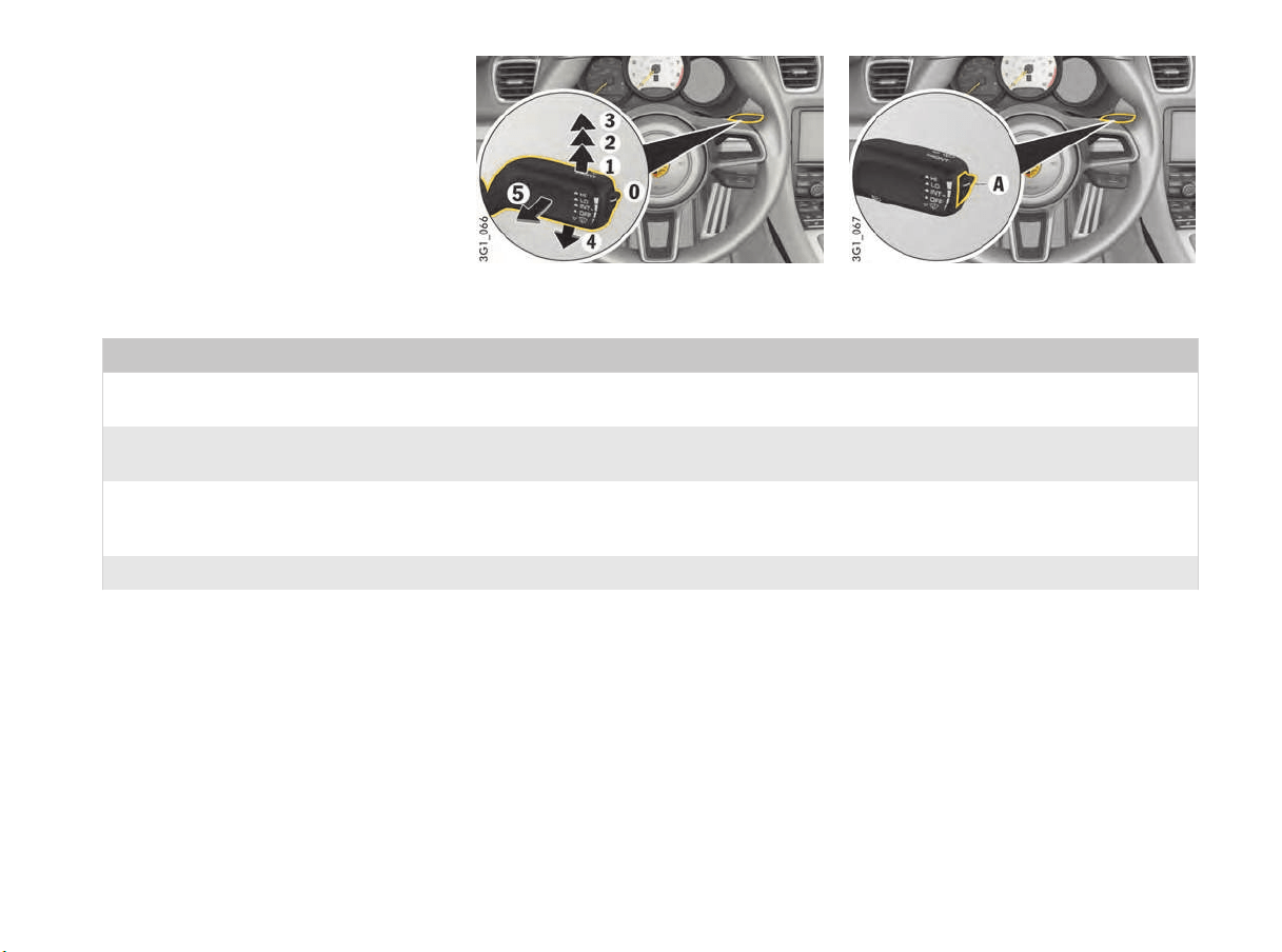
Lights, Turn Signals and Windshield Wipers 69
Brief Overview – Windshield wipers
This brief overview does not replace the
information provided under “WINDSHIELD WIPER/
WASHER STALK”.
Warnings, in particular, are not replaced by
this brief overview.
Windshield wiper stalk Switch for rain sensor sensitivity (A)
What do I want to do? What do I have to do?
Wipe automatically at front
(rain sensor operation)
Press the stalk to detent position 1.
Adjusting the rain sensor
operation sensitivity
Adjust switch A on the right of the stalk upwards (wipe more often) or downwards (wipe less often).
Wipe at front Slow: Press the stalk to detent position 2.
Fast: Press the stalk to detent position 3.
Once: Briefly move stalk to position 4 (holding stalk in position 4 accelerates wiping action).
Spray and wipe at front Pull stalk towards the steering wheel at position 5 and hold.
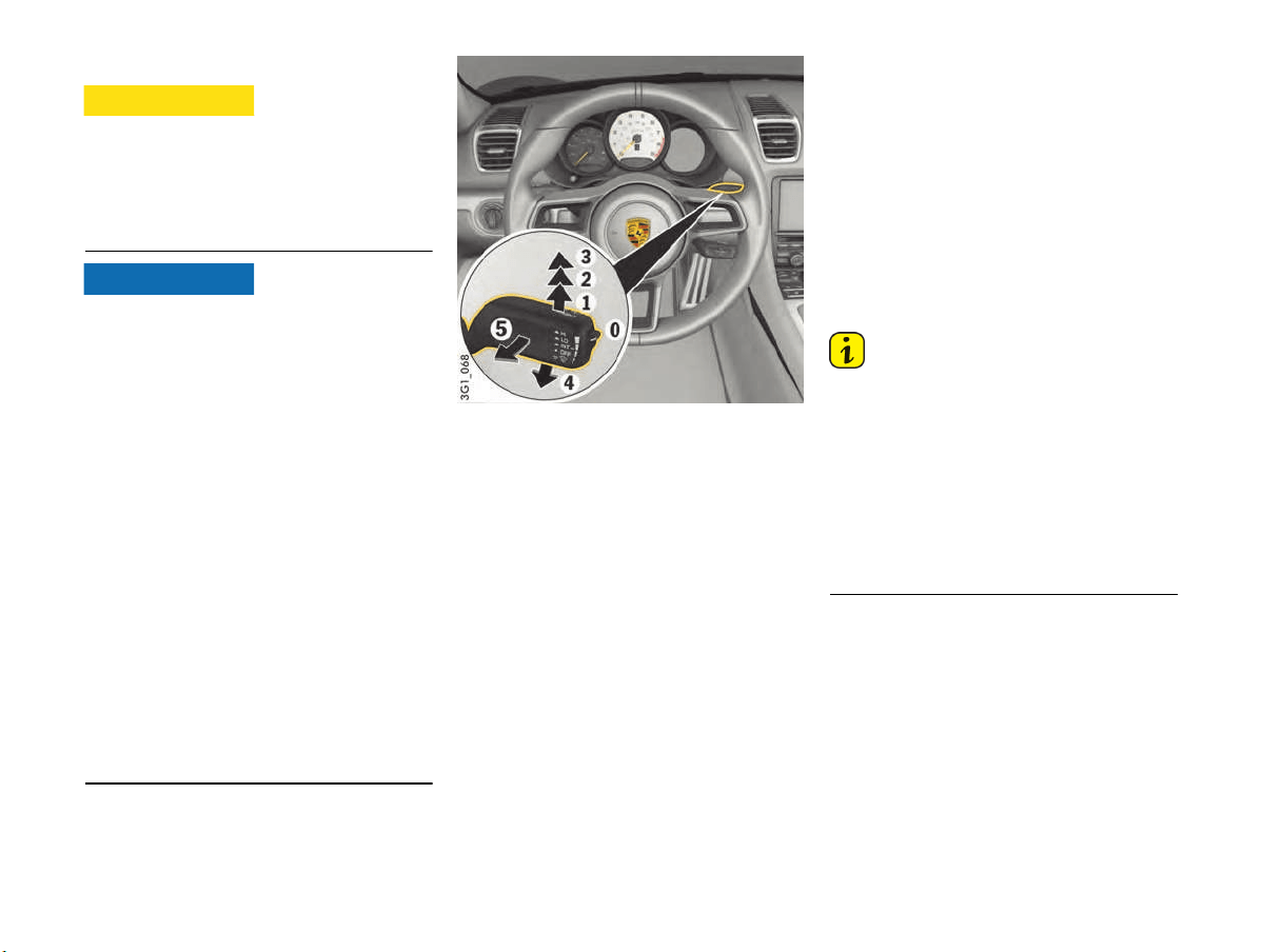
70 Lights, Turn Signals and Windshield Wipers
Windshield Wiper/Washer Stalk
In rain sensor operation, the windshield wipers
wipe automatically if moisture is detected on the
windshield.
f Always switch off windshield wipers before
cleaning the windshield to avoid unintentional
operation (rain sensor operation).
Risk of damage to the luggage compartment lids,
windshield, rear window and wiper system.
f Only wipe the windshield when sufficiently wet,
otherwise it could become scratched.
f Loosen frozen wiper blades before starting
to drive.
f Do not operate a frozen headlight washer
system.
f Always switch off windshield wipers in car
washes to prevent them wiping unintentionally
(rain sensor operation).
f Do not operate headlight washer system in car
washes.
f Always switch off windshield wipers before
cleaning the windshield to avoid unintentional
operation (rain sensor operation).
f Always hold the wiper arm securely when
replacing the wiper blade.
f Always switch off windshield wipers before
opening the luggage compartment lids
(wiper switch in position 0).
f When replacing wiper blades, observe different
lengths of the wiper blades.
Windshield wiper and headlight washer
system
0 – Windshield wipers off
When the windshield wipers are switched off and
also occasionally after the ignition is switched off,
the wipers move up slightly from their rest position
so that the wiping edges are aligned correctly.
1 – Rain sensor operation,
Windshield wipers
f Press the wiper stalk upwards to the first click.
2 – Windshield wipers – slow
f Press the wiper stalk upwards to the second
click.
3 – Windshield wipers – fast
f Press the wiper stalk upwards to the third
click.
4 – One-touch operation
Windshield wipers
f Press the wiper stalk downwards.
The windshield wipers carry out one wiping
cycle.
5 – Windshield wiper and washer system
f Pull wiper stalk towards the steering wheel.
The system wipes as long as the stalk is pulled
towards the steering wheel.
When the wiper stalk is released, a few drying
wipes are performed.
After every 10 wipes on the windshield,
the headlights are cleaned automatically.
Information
f If heavily soiled, repeat wash.
f Persistent dirt (e.g. insect residues) should
be removed regularly.
For information on car care:
f Please see the chapter “CAR CARE
INSTRUCTIONS” on page 174.
Windshield wiper blades that are in perfect
condition are vital for a clear view.
f Please see the chapter “WIPER BLADES”
on page 168.
Fitting ice or sun shields and wiper blade
replacement
f After switching off the ignition, press the wiper
stalk once downwards 4.
The wipers move upwards to an angle of
approx. 45°.
Cleaning windshield
CAUTION
h
NOTICE
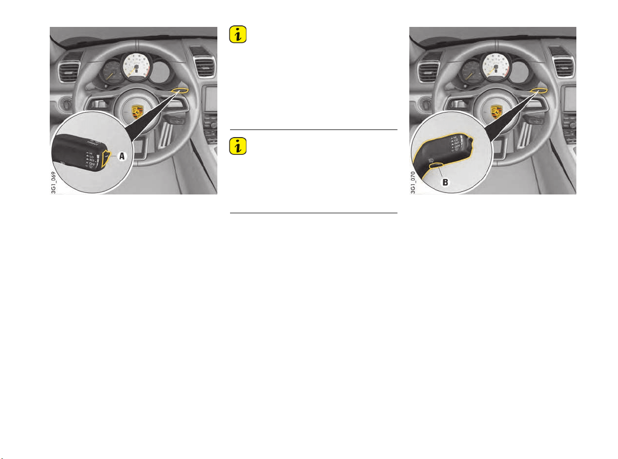
Lights, Turn Signals and Windshield Wipers 71
Rain sensor operation, windshield wipers
In rain sensor mode, the amount of rain on the
windshield is measured. The wipe interval is
automatically controlled accordingly.
Rain sensor operation is activated automatically at
speeds of less than approx. 2.5 mph (4 km/h)
when the windshield wipers are switched on.
If a speed of approx. 5 mph (8 km/h) is exceeded,
the system switches to the preselected wiper
speed.
Information
f If the wiper stalk is in position 1 when the
ignition is switched on, the rain sensor is
activated as soon as the vehicle speed
exceeds approx. 2.5 mph (4 km/h).
f If the wiper stalk is in position 2 or 3 when the
ignition is switched on, the windshield wipers
remain switched off until the wiper stalk is
actuated.
Information
The wiper is stopped when the luggage
compartment lid is opened.
After closing the luggage compartment lid, the
wiper stalk must be operated in order to switch
the wiper back on.
Adjusting the rain sensor sensitivity
f Move switch A upwards –
high sensitivity.
The setting is confirmed by one wipe of
the windshield.
f Move switch A downwards –
low sensitivity.
Activating and deactivating automatic rain
sensor operation in the multi-function display
For information on automatic rain sensor
operation:
f Please see the chapter “ACTIVATING AND
DEACTIVATING RAIN SENSOR OPERATION”
on page 103.
Headlight washer system
(on vehicles with Bi-Xenon
TM
headlights and
PDLS)
The washer sprays only while low beam or
high beam is activated.
f Press button B under the wiper stalk.
After every 10 wipes on the windshield, the
headlights are cleaned automatically as well.
The wipe count starts from zero again when the
low beam is switched off.

72 Lights, Turn Signals and Windshield Wipers
Information
f Clean the wiper blades with window cleaner
at regular intervals, especially after washing
the vehicle in a car wash.
We recommend Porsche window cleaner.
If the wiper blades are very dirty (e.g. soiled
with insect remains), they can be cleaned with
a sponge or cloth.
If the wiper blades judder or squeak, this may
be due to the following:
– If the vehicle is washed in an automatic car
wash, wax residues may adhere to the
windshield. These wax residues can be
removed only by using window cleaner
concentrate.
Please see the chapter “WASHER FLUID”
on page 167.
– The wiper blades may be damaged or worn.
f Replace damaged wiper blades immediately.
f Contact an authorized Porsche dealer for
more information.

Instrument Panel and Multi-Function Display 73
Instrument Panel and Multi-Function Display
Instrument Panel USA Models.........................74
Instrument Panel Canada Models....................75
Displays on the Instrument Panel....................76
Battery/Alternator .........................................77
Check Engine
(Emission Control) .........................................77
Acoustic Signals ...........................................77
Operating the Multi-Function Display on the
Instrument Panel ...........................................78
Vehicle Menu ................................................81
Audio Menu...................................................83
Phone Menu..................................................84
Map Menu ....................................................84
Navigation Menu ...........................................85
Trip Menu .....................................................86
Tire Pressure Menu (Tire Pressure Monitoring
System, TPMS) .............................................86
Chrono Menu (Stopwatch)..............................95
Gear Shift Assist Menu ..................................97
G-Forces Menu..............................................98
Performance Menu........................................98
Vehicle Settings on the
Multi-Function Display ....................................99
Overview of Warning and
Information Messages..............................109
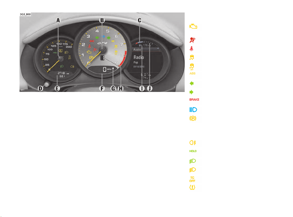
74 Instrument Panel and Multi-Function Display
Instrument Panel USA Models
A Speedometer
B Tachometer
C Multi-function display
For information on warning and information
messages of the multifunction display on the
instrument panel:
f Please see the chapter “OVERVIEW OF
WARNING AND INFORMATION MESSAGES”
on page 109.
D Reset button for trip counter display/
brightness setting for instrument panel
E Odometer
F Digital speedometer
G Upshift indicator
H Gear display
I Marking showing position of filler flap
J Fuel gauge
Warning and indicator lights on the
tachometer
Warning and indicator lights on the
speedometer
Emission control warning light
(Check Engine)
Airbag warning light
Safety belt warning light
PSM warning light
PSM OFF warning light
ABS warning light
Turn signal, left
Turn signal, right
Brake warning light
High beam indicator light
Electric parking brake warning light
Rear fog light indicator light
HOLD function indicator light
Low beam indicator light
PDLS warning light
TC OFF warning light
Tire pressure warning light
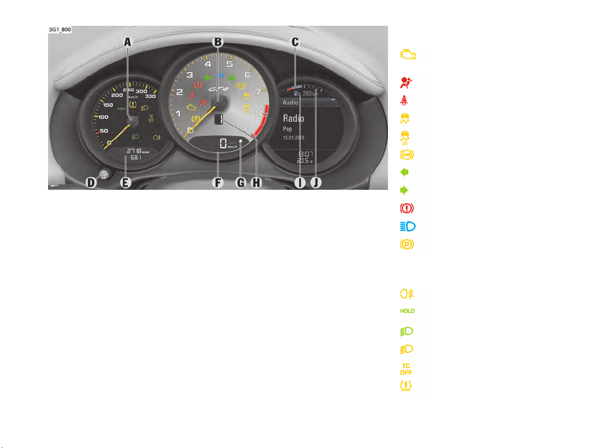
Instrument Panel and Multi-Function Display 75
Instrument Panel Canada Models
A Speedometer
B Tachometer
Multi-function display
For information on warning and information
messages of the multifunction display on the
instrument panel:
f Please see the chapter “OVERVIEW OF
WARNING AND INFORMATION MESSAGES”
on page 109.
C Reset button for trip counter display/
brightness setting for instrument panel
D Odometer
E Digital speedometer
F Upshift indicator
G Gear display
H Marking showing position of filler flap
I Fuel gauge
Warning and indicator lights on the
tachometer
Warning and indicator lights on the
speedometer
Emission control warning light
(Check Engine)
Airbag warning light
Safety belt warning light
PSM warning light
PSM OFF warning light
ABS warning light
Turn signal, left
Turn signal, right
Brake warning light
High beam indicator light
Electric parking brake warning light
Rear fog light indicator light
HOLD function indicator light
Low beam indicator light
PDLS warning light
TC OFF warning light
Tire pressure warning light

76 Instrument Panel and Multi-Function Display
Displays on the Instrument Panel
A – Speedometer
The analogue display A is located on the left next
to the tachometer in the instrument panel.
B – Tachometer
The start of the red zone on the tachometer or rev-
counter scale is a visual warning of the maximum
permissible engine speed.
If the red zone is reached during acceleration, fuel
feed is interrupted in order to protect the engine.
C – Multi-function display
For information on the multi-function display:
f Please see the chapter “OPERATING THE
MULTI-FUNCTION DISPLAY ON THE
INSTRUMENT PANEL” on page 78.
D – Reset button for trip counter display/
brightness setting for instrument lighting
Resetting trip counter display
f Press rotary switch D for approx. 1 second.
The trip counter display is reset to “0”.
Adjusting brightness of instrument lighting
For information on adjusting the brightness of the
instrument lighting:
f Please see the chapter “ADJUSTING INTERIOR
LIGHTS” on page 103.
E – Odometer
The displays for the total mileage and individual
trips are integrated in the speedometer on the
instrument panel.
The upper display counts the total mileage, the
lower display shows individual trips.
After exceeding 6,213 miles or 9,999 kilometers,
the trip counter returns to 0.
F – Digital speedometer
The digital speedometer F is integrated in the
tachometer on the instrument panel.
G – Upshift indicator
The consumption-oriented shift indicator to the
right of the digital speed display on the
tachometer helps you to develop a fuel-saving
driving style.
The upshift indicator lights up - prompting you to
shift up to the next-higher gear - depending on the
selected gear, engine speed and accelerator
pedal position.
f Change to the next-higher gear when the
upshift indicator lights up.
H – manual transmission gear display
When the engine is running, the display shows the
currently engaged gear.
J – Fuel gauge
The fuel gauge displays the contents of the tank,
and depending on the settings, the fuel range
when the ignition is on.
For information on adjusting the fuel gauge:
f Please see the chapter “ADAPTING FUEL
GAUGE” on page 102.
For information on fuel quality and refill capacities:
f Please see the chapter “FILLING CAPACITIES”
on page 223.
For information on fuel and refueling:
f Please see the chapter “FUEL” on page 171.
If the vehicle’s inclination changes (e.g. uphill/
downhill driving), minor deviations in the gauge
may occur.
Fuel reserve warning
If less than approximately 2.6 U.S. gallons
(10 liters) remains in the tank, the warning light on
the multi-function display lights up when the
ignition is switched on or the engine is running.
f Refuel at the next opportunity.
A shortage of fuel may damage the emission
control system.
f Never drive the tank dry.
f If the warning lights have come on, do not take
bends at high speed.
For information on the emission control system:
f Please see the chapter “EMISSION CONTROL
SYSTEM” on page 168.
NOTICE

Instrument Panel and Multi-Function Display 77
Battery/Alternator
The warning message “Generator fault
Park vehicle safely” will appear on the multi-
function display in the instrument panel if the
vehicle electrical system voltage drops
significantly.
f Stop at a safe place and switch the engine off.
For information on warning messages on the
multi-function display:
f Please see the chapter “OVERVIEW OF
WARNING AND INFORMATION MESSAGES”
on page 109.
Possible causes
– Defect in the battery charging system
– Broken drive belt
Risk of engine damage.
The engine cooling does not function if the drive
belt is torn.
f Do not continue driving.
f Have the fault corrected.
f Please contact a qualified specialist workshop.
We recommend that you get an authorized
Porsche dealer to do this work as they have
trained workshop personnel and the necessary
parts and tools.
Check Engine
(Emission Control)
Warning light
The emission control system detects malfunctions
that could cause increased pollutant emissions or
consequential damage, etc. well in advance.
Faults are indicated by the warning light on the
instrument panel which then either lights up
continuously or flashes.
The faults are recorded in the control unit’s fault
memory.
The warning light on the instrument panel lights up
when the ignition is switched on as a lamp check
and goes out approx. 1 second after the engine
starts.
The warning light on the instrument panel flashes
to indicate operating states (e.g. engine misfiring)
which may cause damage to certain parts of the
emission control system.
f In this case, immediately reduce the engine
load by easing off the accelerator pedal.
In order to avoid consequential damage to the
engine or the exhaust-gas cleaning system
(e.g. catalytic converter):
f We recommend that you get an authorized
Porsche dealer to do this work as they have
trained workshop personnel and the necessary
parts and tools.
Risk of damage to the emission control system.
If the warning light on the instrument panel
continues flashing even when you have eased off
the accelerator pedal, the emission control
system may overheat.
f Stop as soon as possible in a safe place.
Make sure that combustible materials, such as
dry grass or leaves, cannot come into contact
with the hot exhaust system.
f Switch off the engine.
f Have the fault corrected.
Acoustic Signals
A speaker in the instrument panel generates
acoustic signals.
The warning message “Instrument cluster/
Park Assist audio fault Service required” will
appear on the multi-function display in the
instrument panel if a speaker fault occurs.
The speaker cannot generate acoustic signals.
f Please see the chapter “OVERVIEW OF
WARNING AND INFORMATION MESSAGES”
on page 109.
Warning message
NOTICE
NOTICE
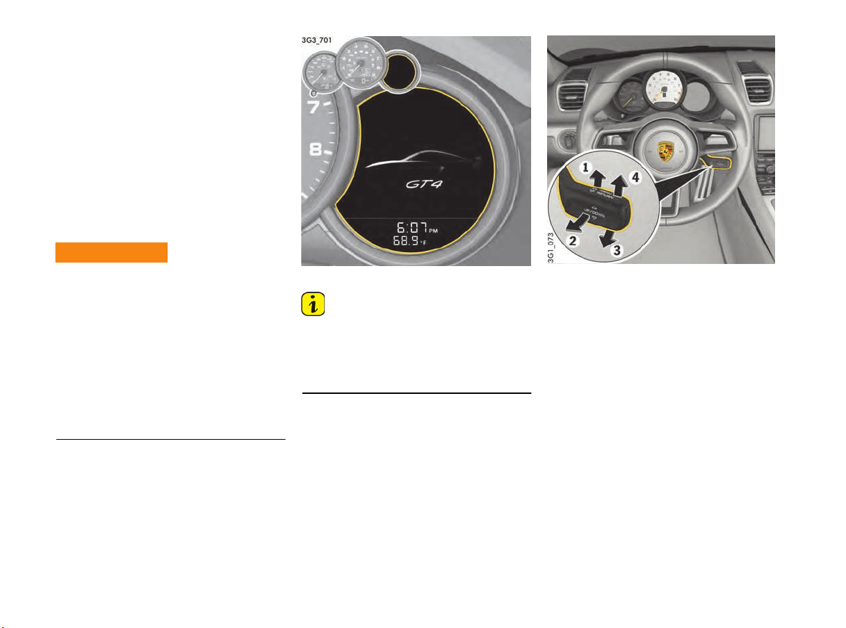
78 Instrument Panel and Multi-Function Display
Operating the Multi-Function
Display on the Instrument Panel
On the multi-function display, you can view
information relating to the relevant vehicle
equipment, operate the audio source (radio, CD,
iPod, etc.), check the oil level, check the tire
pressure, use the stopwatch or operate the
navigation system.
You can also modify different vehicle settings in
the “Vehicle” menu.
It is not possible to describe all details of the
functions in this Owner’s Manual. The examples
clearly demonstrate the functional principle and
clarify the menu structure.
You may be distracted from paying attention to the
road if you set or operate the multi-function
display, radio, navigation system, telephone or
other equipment when driving. You may lose
control of the vehicle.
f Operate the equipment while driving only if the
traffic situation allows you to do so safely.
f Carry out any complicated operating or setting
procedures only while the vehicle is stationary.
Multi-function display
Information
The multi-function display is only active when the
ignition is on.
Certain menus are only available when the vehicle
has stopped, e.g. the adjustment menu for tire
pressure monitoring system.
Operating principle
The multi-function display is operated with the
lower lever on the right of the steering column.
Selecting menu, function, setting option
f Push the lever downwards (position 3) or
upwards (position 4).
Confirming selection (Enter)
f Push the lever forward (position 1).
Moving back one or several selection levels
f Pull the lever towards the steering wheel
(position 2) once or several times.
Operation of the multi-
function display
, radio,
navigation system,
telephone etc. during
driving.
WARNING
h

Instrument Panel and Multi-Function Display 79
A - Fuel gauge
B - Title area with menu indicator
C - Information area
D - Status area
Areas on the multi-function display
A – Fuel gauge
The fuel gauge A displays the contents of the tank,
and depending on the settings, the fuel range
when the ignition is on.
For information on adjusting the fuel gauge:
f Please see the chapter “ADAPTING FUEL
GAUGE” on page 102.
For information on fuel quality and refill capacities:
f Please see the chapter “FILLING CAPACITIES”
on page 223.
For information on fuel and refueling:
f Please see the chapter “FUEL” on page 171.
If the vehicle’s inclination changes (e.g. uphill/
downhill driving), minor deviations in the gauge
may occur.
Fuel reserve warning
If less than approximately 2.6 U.S. gallons
(10 liters) remain in the tank, the warning light on
the multi-function display lights up when the
ignition is switched on or the engine is running.
f Refuel at the next opportunity.
A shortage of fuel may damage the emission
control system.
f Never drive the tank dry.
f If the warning lights have come on, do not take
bends at high speed.
For information on the emission control system:
f Please see the chapter “CAR CARE
INSTRUCTIONS” on page 174.
B – Title area with menu indicator
The menu item currently selected is displayed in
the title area B.
The menu indicator (gray bar) on the right shows
the position of the current menu item in the overall
menu and displays the number of other menu
items on this menu level.
The wider the menu indicator, the fewer menu
items the current menu contains.
C –
Information area
The information area C displays the menu items
currently available for selection or after a menu
item is selected, information relating to this menu
item or other selection options.
D – Status area
Basic information, such as time and temperature,
as well as warnings are displayed in the status
area D.
The display contents of the status area can be
individually adapted.
For information on adapting the multi-function
display:
f Please see the chapter “ADAPTING
APPEARANCE OF MULTI-FUNCTION DISPLAY”
on page 99.
Activating functions, opening submenus
and accessing setting options from the
main menu areas
Push the right lower lever on the steering wheel
forwards (position 1) to access menus, other
functions and setting options regardless of the
main menu area.
Browsing through long lists
When searching for an entry in long telephone and
audio lists on vehicles with PCM, you can skip
directly to other entries with the same first letter.
f Hold the control stalk in position 3 or 4.
A letter selection screen appears.
Select the desired first letter and confirm.
The marking skips to the first list entry beginning
with the letter selected.
NOTICE
1. Select main menu
and confirm.
2. Select function, submenu or setting option
and confirm.
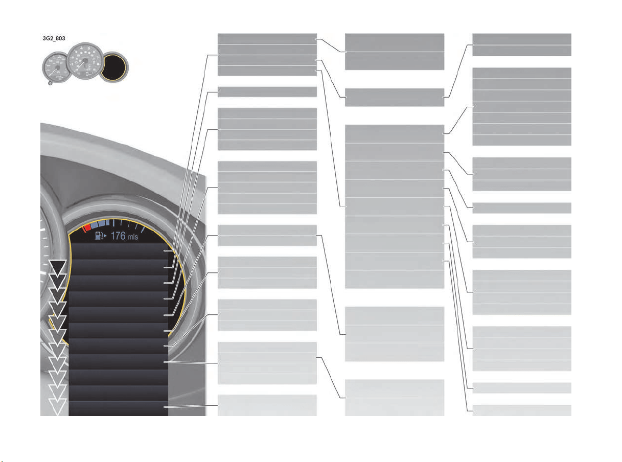
80 Instrument Panel and Multi-Function Display
Vehicle
Audio
Telephone
Map
Navigation
Trip
TPMS
Chrono
Gearshift assistant
G-Force
Performance
Info
Oil measurement
Limits
Settings
Station/Track
Answer/Reject/End
Phonebook
Previous calls
Received calls
Manual zoom
Auto zoom
3D map
North up
Show destination/position
Destination input
Start/Stop route guidance
Since
Total
To destination
Fill info
Tire type
Circuits
Start
Stop
Round
Interim
Power
Torque
Current speed
Set speed
Menu scope
Audio
Vehicle menu
Upper line
PCM display
Lower line
Brightness
Exterior lights
Interior lights
Wiper
Door lock/unlock
Air flow
Vent. panel
Auto air circ.
Time
Date
DST (+01:00)
Time Chrono
Speedometer
Temperature
Tire pressure
Consumption
German/French ...
Warn. tones
Messages
Service interval
Limit 1/Limit 2
Display
Light & Visibility
Locking
Air conditioning
Date & Time
Units
Language
Volume
Fact. settings
Last destination
Stored destinations
POIs
Cont.
Reset
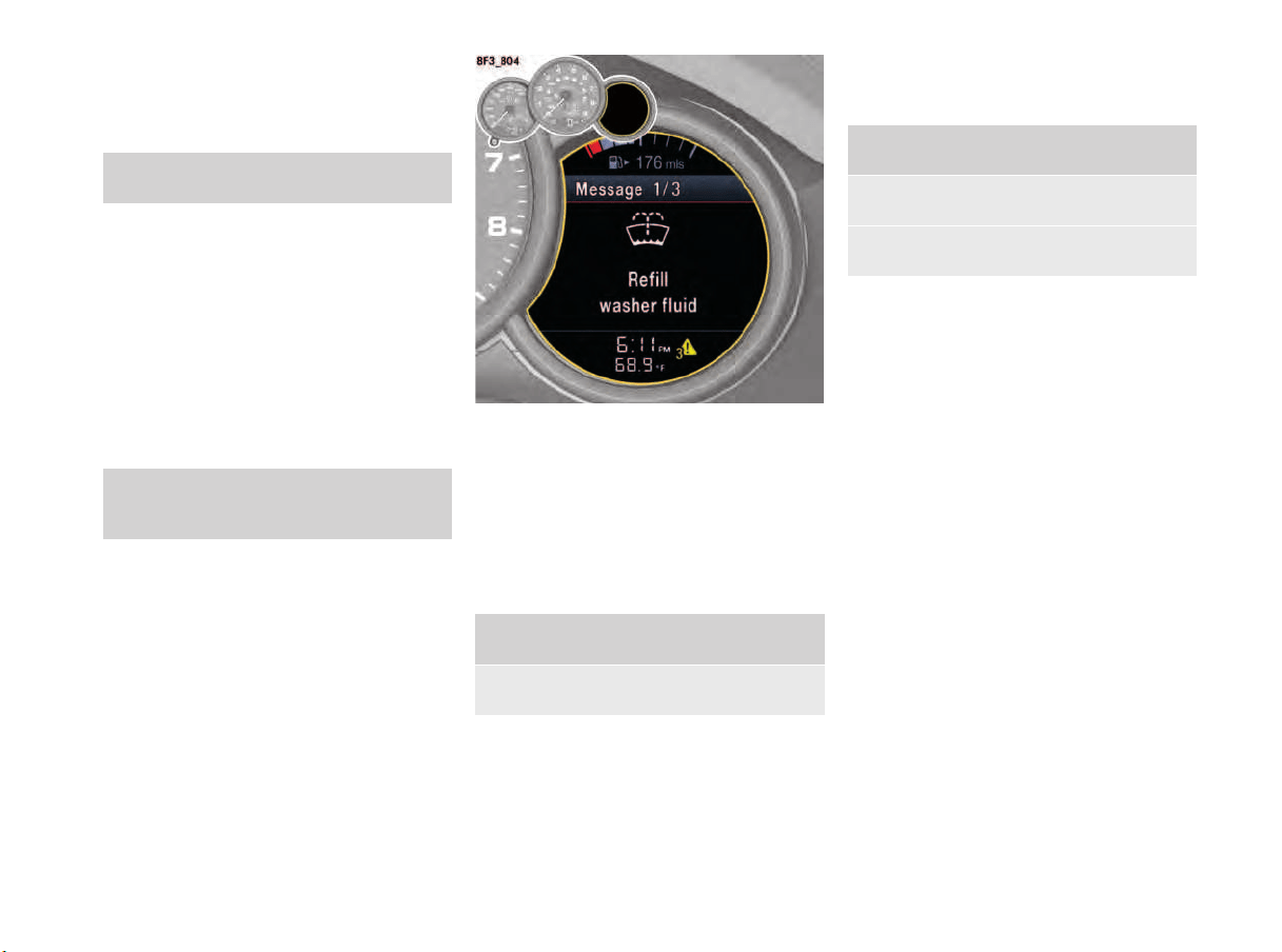
Instrument Panel and Multi-Function Display 81
Vehicle Menu
A large amount of vehicle information can be
displayed and vehicle settings made in the
“Vehicle” main menu.
The vehicle information display can be adapted
individually.
For information on adapting the vehicle menu:
f Please see the chapter “ADAPTING DISPLAY
CONTENTS IN VEHICLE INFORMATION AREA”
on page 99.
Displaying vehicle information
Pending warning messages, information on
forthcoming service intervals and the average fuel
consumption can be viewed in the “Info” sub-menu
of the “Vehicle” main menu area.
Displaying messages
All current warning messages and vehicle
messages can be viewed on the multi-function
display.
The warning symbol in the lower status area
indicates the number of pending warning
messages.
If several warning messages are pending, you can
browse through the message list.
Displaying service intervals
The internal mileage counter indicates when the
next vehicle service is due.
Available service interval displays:
–“Service”
–“Interm. service”
–“Oil change”
1. Select “Vehicle”
main menu.
1. Main menu: Select “Vehicle”
> “Info”
and confirm.
1. Main menu “Vehicle”
> “Info”
2. Select “Messages”
and confirm.
1. Main menu “Vehicle”
> “Info”
2. Select “Service intervals”
and confirm.
3. Select the desired service interval
and confirm.
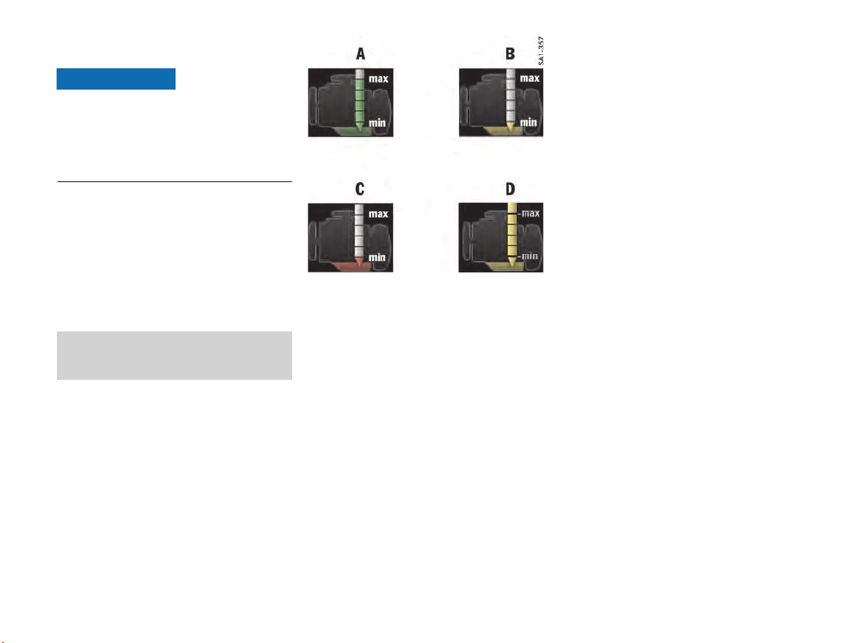
82 Instrument Panel and Multi-Function Display
Display and measurement of the engine
oil level
Risk of engine damage due to inadequate
lubrication.
f Regularly check the oil level each time before
refuelling.
f Do not allow the oil level to fall below the
minimum mark.
Prerequisites for the oil-level gauge:
1. Park the vehicle on a level surface.
2. Switch off engine, which is now at operating
temperature.
3. Wait for approx. 1 minute.
4. Select the “Oil measurement” function on the
multi-function display.
Selecting the Oil measurement function on
the multi-function display
f Please see the chapter “OVERVIEW OF
WARNING AND INFORMATION MESSAGES”
on page 109.
Example displays for oil level
A - Maximum oil level reached
B - Minimum oil level reached
C - Oil level below minimum
D - Oil level above maximum
Measured oil level
The oil level reading is shown on the segment
display in the Oil measurement menu.
If the segments are filled in green up to the top line
(illustration A), the oil level has reached the
maximum mark.
f Under no circumstances add engine oil.
If the bottom segment is shown in yellow
(illustration B), the oil level has reached the
minimum mark.
The message “Oil level minimum reached
Refill oil” appears on the multi-function display.
f Add engine oil immediately.
If the bottom segment is red (illustration C), the oil
level has dropped below the minimum mark.
The message “Oil level below min. Refill oil at
once Do not drive on” appears on the multi-
function display.
f Add engine oil immediately.
Top-up quantity
The difference between the minimum and
maximum marks on the segment display is
approx. 1.8 quarts (1.7 liters).
f Never add more engine oil than required to
reach the maximum mark.
If the segments are shown in yellow up to the top
edge (illustration D), this indicates that the
maximum engine filling capacity has been
exceeded. Exceeding the maximum capacity may
result in blue smoke formation and cause long-
term damage to the catalytic converters
depending on the overfill quantity and various
external influences.
If too much engine oil was added, the message
“Oil level above maximum Consult a
workshop Driving permitted” appears on the
multi-function display.
f Have the oil quantity corrected at the next
opportunity.
Please contact an authorized Porsche dealer.
1. Main menu: Select “Vehicle”
> “Oil measurement”
and confirm.
NOTICE

Instrument Panel and Multi-Function Display 83
Measuring the oil level after topping up
engine oil or opening the rear lid
The oil level can be checked after waiting for
approx. 1 minute with the vehicle parked on a level
surface and the engine at operating temperature.
If the rear lid is opened when the engine is cold
(e.g. in order to top up engine oil), the oil level
cannot be displayed for a certain time.
The message “No inform./oil level available
now” appears on the multi-function display.
f Engine oil should therefore only be topped up
with the engine at operating temperature. This
ensures short waiting times for the soonest
possible oil level display.
Failure
If the oil-level indicator fails, the message “Oil
level measurement fault Consult a workshop
Driving permitted” appears on the multi-function
display.
Setting speed limits
If a speed limit is preset and activated on the multi-
function display, a warning message appears if
the speed limit is exceeded.
A speed limit can be used to remind the driver to
keep to the maximum speed permitted for the tire
type fitted to the vehicle, for example.
Setting a speed limit
You can either adopt the current speed of the
vehicle or specify your own speed limit.
Activating and deactivating speed limits
Adjusting vehicle settings
Various vehicle settings can be modified in the
“Settings” submenu.
For information on modifying vehicle settings:
f Please see the chapter “PERFORMANCE
MENU” on page 98.
Audio Menu
In the “Audio” main menu, you can select a radio
station either from the station list or the list of
stored stations, depending on the settings, or a
track from the active audio source, e.g. disc.
For information on adjusting audio menu settings:
f Please see the chapter “ADAPTING DISPLAY
CONTENTS OF AUDIO MAIN MENU”
on page 99.
1. Main menu: Select “Vehicle”
> “Limits”
and confirm
1. Main menu “Vehicle”
> “Limits”
2. Select
“Limit 1: ---” or
“Limit 2: ---”
and confirm.
3. Select “Current speed” or
“---”
and confirm.
1. Main menu “Vehicle”
> “Limits”
2. Select
“Limit 1: ---” or
“Limit 2: ---”
and confirm.
3. Select “Active”
4. Confirm your selection.
Limit is active.
Limit is not active.
1. Main menu: Select “Audio”
and confirm.
2. Select the desired radio station or track
and confirm.

84 Instrument Panel and Multi-Function Display
Phone Menu
In the “Phone” main menu, you can retrieve
telephone numbers stored in the phonebook or in
lists of most recently dialled or received calls.
Dialling telephone number
Answering calls
Rejecting calls
Ending a call
Making multiple calls simultaneously
During an active telephone conversation, you have
the option of starting another telephone
conversation.
You can have a separate conversation with the
person you have called or alternatively start a
conference call together with the other caller.
Making additional calls
During a current call:
Switching between callers
Adding a caller to a conference call
Map Menu
In the “Map” main menu, you can view and modify
the map display of the navigation system.
Modifying map display
Available display options:
–“Auto zoom”
The scale of the map is set automatically from
the current position of the vehicle to the next
navigation maneuver point.
–“3D map”
Three-dimensional map display.
–“North up”
The map always faces north.
1. Main menu: Select “Phone”
and confirm.
1. Main menu “Phone”
2. Select
“Phonebook” or
“Previous calls” or
“Received calls”
and confirm.
3. Select the desired telephone number
and confirm.
1. Main menu “Phone”
2. Select “Answer”
and confirm.
1. Main menu “Phone”
2. Select “Reject”
and confirm.
1. Main menu “Phone”
2. Select “End call”
and confirm.
1. Main menu “Phone”
2. Select “New call”
and confirm.
1. Main menu “Phone”
2. Select “Swap”
and confirm.
1. Main menu “Phone”
2. Select “Conference”
and confirm.
1. Main menu:
Select “Map”.
1. Main menu: Select “Map”
and confirm.
2. Select display option
and confirm.
3. Confirm your selection.
Function is active.
Function is not active.

Instrument Panel and Multi-Function Display 85
Enlarging and reducing map display
The zoom factor of the map display can be
adapted individually.
Displaying current location or destination
You can view the navigation destination or current
vehicle position on an enlarged section of the
map.
Navigation Menu
In the “Navigation” main menu, you can enter a
navigation destination, start route guidance and
view the navigation information for an active route.
Entering navigation destination
You can enter a navigation destination in the multi-
function display.
Only navigation destinations from the list of
previous destinations or from the list of preset
POIs or stored destinations can be selected.
Starting route guidance
If route guidance is inactive and you have entered
a new navigation destination you can then start
route guidance.
Stopping route guidance
You can stop route guidance while in progress.
1. Main menu: Select “Map”
> “Manual zoom”
and confirm.
2. Select the desired zoom setting
and confirm.
1. Main menu “Map”
2. Select
“Show destination” or
“Show position”
and confirm.
1. Main menu: Select “Navigation”
and confirm.
1. Main menu “Navigation”
> “Destination input”
2. Select
“Last destination” or
“Stored destination” or
“POIs”
and confirm.
3. Select the desired navigation destination
and confirm.
1. Main menu “Navigation”
2. Select “Start route guidance”
and confirm.
1. Main menu “Navigation”
2. Select “Stop route guidance”
and confirm.
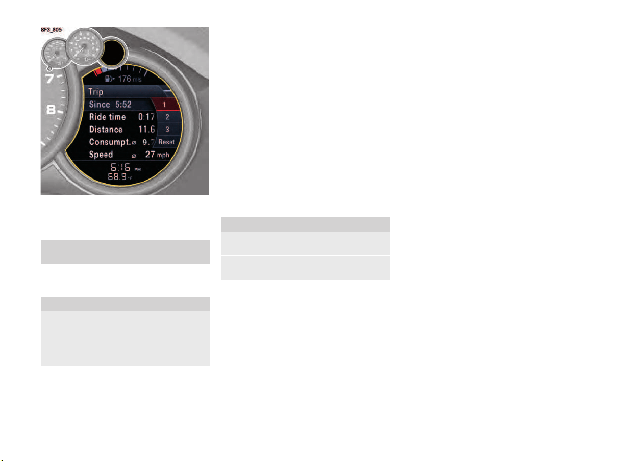
86 Instrument Panel and Multi-Function Display
Trip Menu
In the “Trip” main menu, you can retrieve and
reset driving data.
Displaying driving data
There are three driving data displays available.
Available driving data:
–“Since”
Driving data since the last vehicle start.
The driving data is reset automatically once
the vehicle has remained stationary for 2 hours
(with the ignition switched off).
–“Total”
Cumulative driving data.
The driving data is added progressively until a
reset is performed. The data is retained even
if the ignition key is removed.
–“To destination”
Driving data up to navigation destination.
If route guidance is active, the driving data is
calculated and displayed up to the navigation
destination.
Resetting driving data
The selected driving data display can be reset.
Tire Pressure Menu (Tire Pressure
Monitoring System, TPMS)
This device complies with Part 15 of the FCC
Rules and RSS-210 of Industry Canada.
Operation of this device is subject to the following
two conditions:
1. This device may not cause harmful
interference, and
2. This device must accept any interference
received including interference that may cause
undesired operation.
Changes or modifications not expressly approved
by the party responsible for compliance could void
the user's authority to operate the equipment.
Each tire, including the spare (if provided), should
be checked monthly when cold and inflated to the
inflation pressure recommended by the vehicle
manufacturer on the vehicle placard or tire
inflation pressure label. (If your vehicle has tires of
a different size than the size indicated on the
vehicle placard or tire inflation pressure label, you
should determine the proper tire inflation pressure
for those tires).
For information on the tire inflation pressure label:
f Please see the chapter “TIRES AND WHEELS”
on page 186.
As an added safety feature, your vehicle has been
equipped with a Tire Pressure Monitoring System
(TPMS) that illuminates a low tire pressure telltale
(warning light) when one or more of your tires is
significantly under-inflated.
Accordingly, when the low tire pressure telltale
illuminates, you should stop, check your tires as
soon as possible, and inflate them to the proper
pressure. Driving on a significantly under-inflated
tire causes the tire to overheat and can lead to tire
failure. Under-inflation also reduces fuel efficiency
1. Main menu:
Select “Trip”.
1. Main menu “Trip”.
2. Select
“1 – Since” or
“2 – Total” or
“3 – To destination”
and confirm.
1. Main menu “Trip”.
2. Select the relevant driving data display
and confirm.
3. Select “Reset”
and confirm.

Instrument Panel and Multi-Function Display 87
and tire tread life, and may affect the vehicle’s
handling and stopping ability.
The display as well as the settings for the Tire
Pressure Monitoring System take place on the
multi-fuction display.
However, the tire pressure must still be set
manually on the wheel.
f Please see the chapter “TIRE PRESSURE FOR
COLD TIRES (68 °F/ 20 °C)” on page 221.
Driving the vehicle with low tire pressure increases
the risk of a tire failure and resulting loss of
control. Furthermore, low tire pressure increases
rate of wear of the affected tires.
Please note that the Tire Pressure Monitoring
System is not a substitute for proper tire
maintenance, and it is the driver's responsibility to
maintain correct tire pressure, even if under-
inflation has not reached the level to trigger
illumination of Tire Pressure Monitoring System
low tire pressure telltale. Low tire pressure
reduces the road safety of the vehicle and
destroys the tire and wheel.
Tire Pressure Monitoring System gives a warning
about tire damage caused by a natural loss in
pressure as well as about a gradual loss of
pressure caused by foreign objects.
Tire Pressure Monitoring System cannot warn you
about tire damage that occurs suddenly (e.g. flat
tire due to abrupt external effects).
f When a red tire pressure warning appears,
stop immediately in a suitable place and check
the tires for damage. If necessary, remedy the
damage with a tire sealant.
f Do not by any means continue to drive with
defective tires.
f Sealing the tire with tire sealant is only an
emergency repair so you can drive to the
nearest authorized Porsche dealer.
The maximum permitted speed is 50 mph
(80 km/h).
3. Do not drive with tires in which the tire
pressure drops again very quickly. In case of
doubt, have tires checked by an authorized
Porsche dealer.
f Defective tires must be replaced immediately
at an authorized Porsche dealer.
Tires must never be repaired under any
circumstances.
f If Tire Pressure Monitoring System is defective
(e.g. defective wheel transmitter), contact an
authorized Porsche dealer immediately and
have the damage repaired.
The tire pressure will not be monitored at all
or will be monitored only partially when Tire
Pressure Monitoring System is defective.
For information on warning messages on the multi-
function display:
f Please see the chapter “OVERVIEW OF
WARNING AND INFORMATION MESSAGES”
on page 109.
f Incomplete entries or selection of the wrong
tires on the multi-function display affect the
accuracy of warnings and messages.
The settings in the tire pressure menu must be
updated following a wheel change or changes
in vehicle loading.
f Use only the pressure differences shown in the
“Fill info” display in the Tire pressure menu
or from the corresponding tire pressure
warning when correcting the tire pressure.
f Tires can lose air over time without a tire
defect being present. A tire pressure warning
will then appear on the multi-function display.
Check the tire pressure at the next opportunity.
Warning light
Your vehicle has also been equipped with a TPMS
malfunction indicator to indicate when the system
is not operating properly.
The TPMS malfunction indicator is combined with
the low tire pressure telltale.
When the system detects a malfunction, the
telltale will flash for approximately one minute and
then remain continuously illuminated. This
sequence will continue upon subsequent vehicle
start-ups as long as the malfunction exists.
When the malfunction indicator is illuminated, the
system may not be able to detect or signal low tire
pressure as intended.
TPMS malfunctions may occur for a variety of
reasons, including the installation of replacement
or alternate tires or wheels on the vehicle that
prevent the TPMS from functioning properly.
f Always check the TPMS malfunction telltale
after replacing one or more tires or wheels on
your vehicle to ensure that the replacement or
alternate tires and wheels allow the TPMS to
continue to function properly.
Maintaining tire pressure
WARNING
h
Attention to TPMS
malfunction indicator
WARNING
h
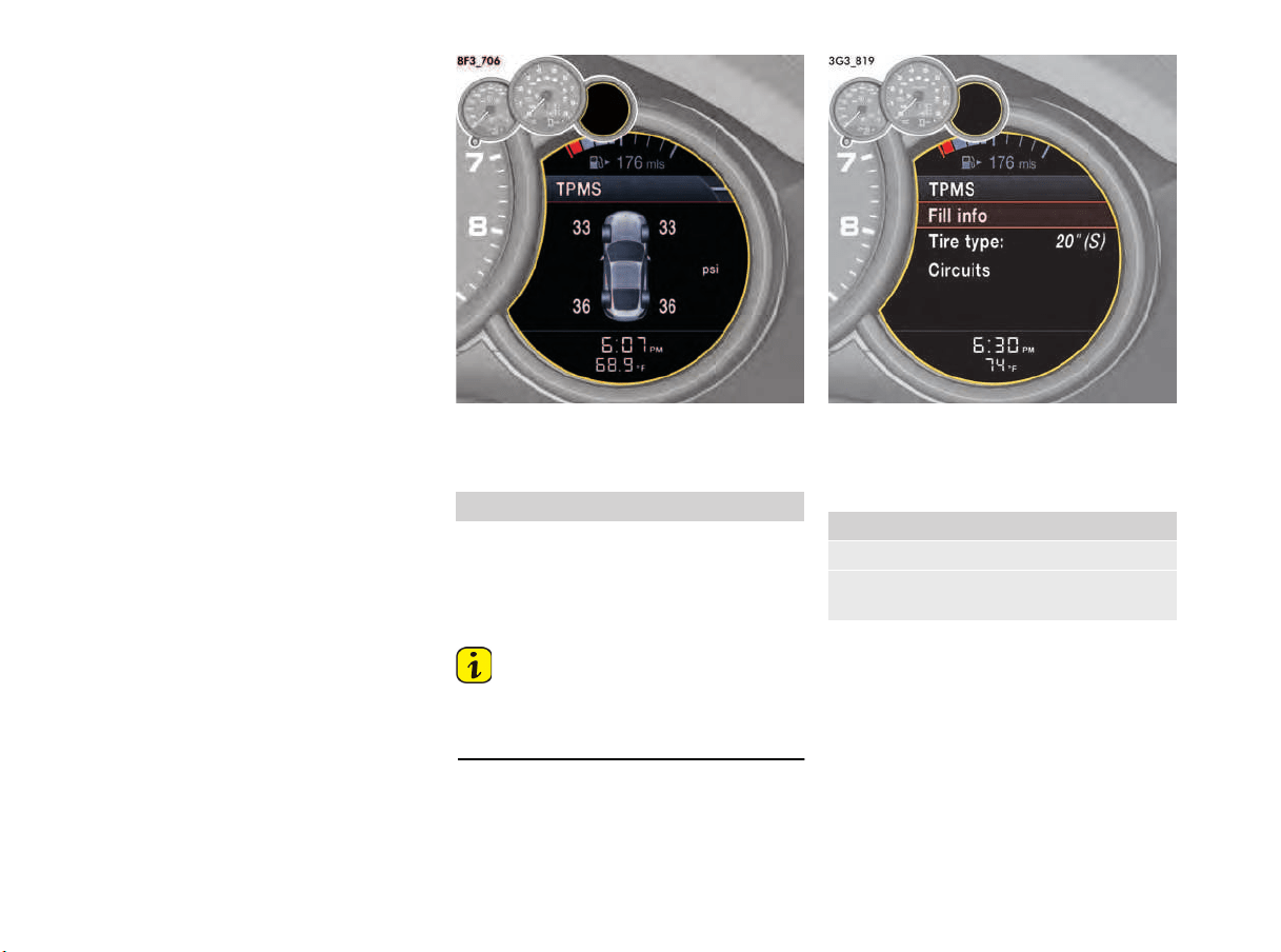
88 Instrument Panel and Multi-Function Display
The warning light in the instrument panel lights up:
–
When a loss in pressure has been detected.
– In the event of a defect in Tire Pressure
Monitoring System or a temporary fault.
– When learning new fitted wheels/wheel
transmitters, as long as the vehicle’s own
wheels have not yet been recognized.
The tire pressure warning light on the instrument
panel goes out only when the cause of the fault
has been rectified.
Overview of Tire Pressure Monitoring
System functions
Tire Pressure Monitoring System offers the
following functions:
– Display of the actual tire pressure while the
vehicle is in motion.
–“Fill info” display:
Display of the deviation from the required
pressure (refilling pressure) at standstill.
–“Tire type” display:
Display of current settings
(when the vehicle is stationary).
– Tire pressure warnings in two stages
(yellow and red warning).
Tire pressure display on the multi-function display
Selecting the TPMS function on the
multi-function display
The “TPMS” function displays the temperature-
dependent tire pressures (actual pressures) in the
four wheels.
You can watch the tire pressure rise as the
temperature increases while driving.
Information
This display is only for information.
f Under no circumstances should the tire
pressures be changed based on this display.
Viewing Fill info in the Tire pressure menu
(only when vehicle is stationary)
You can read the tire pressures to be corrected in
this display.
1. Select main menu “TPMS”
1. Main menu “TPMS”
2. Confirm “TPMS”.
3. Select the “Fill info”
menu and confirm.
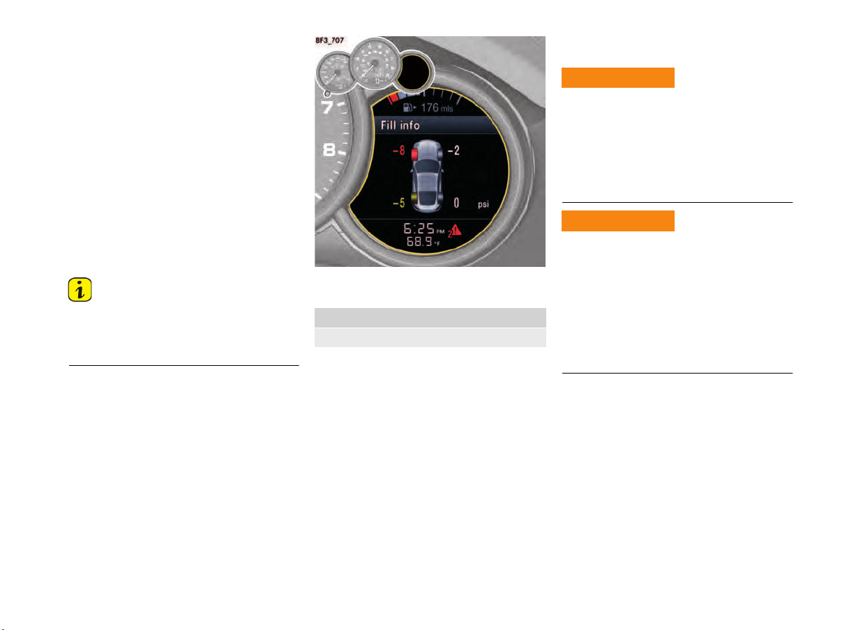
Instrument Panel and Multi-Function Display 89
The tire pressure to be corrected (refill pressure)
is indicated on the displayed wheel.
Example: If
“–1.5 psi (–0.1 bar/ –10 kPa)”
is displayed for the front right tire,
1.5 psi (0.1 bar/ 10 kPa)
must be added to this tire.
The displayed pressures take into account the tire
temperature.
f Use only the pressure values shown in the
“Fill info” display in the “TPMS” main menu or
from the corresponding tire pressure warning
when correcting the tire pressure.
Information
After the ignition is switched on, it can take up to
approx. 1 minute until all tire pressures are
displayed. Dashes (-.-) appear instead of the tire
pressures.
Viewing current settings in the
TPMS menu
Selecting tire type in the TPMS menu
(type and size of fitted tire)
Exceeding the maximum tire speed could result in
a tire burst, causing loss of control of the vehicle.
f Always observe the permissible maximum
speed of the respective tire.
f Porsche recommends obeying all traffic laws
at all times to maintain the safety of yourself
and all vehicle occupants.
Incomplete entries or selection of the wrong tires
on the multi-function display affect correct
indication of warnings and messages.
f The settings must be updated in the “TPMS”
menu after changing a wheel, filling with tire
sealant or adding air (after previous warning
“Check tires”).
f Please see the chapter “RED WARNING –
“Check tires”” on page 93.
1. Main menu “TPMS”
2. Confirm “TPMS”.
Exceeding maximum
rated tire speed
Entering tire data and
display
WARNING
h
WARNING
h

90 Instrument Panel and Multi-Function Display
The new tire type and tire size must be selected
even if the settings for the new set of wheels ar
e
the same as for the old wheels.
Option is selected.
Option is not selected.
Tire selection has only been completed
successfully when the following message appears
on the multi-function display (example):
“No tire pressure monitoring System is
learning”.
f Please see the chapter “CHANGING A WHEEL
AND REPLACING TIRES” on page 94.
Information
Before fitting tires with dimensions that are not
already stored in the multi-function display, the
missing information should be added to the
multi-function display by your authorized Porsche
dealer.
f Please contact your authorized Porsche
dealer.
f Use only tires approved by Porsche.
The available items in the tire pressure menu
depend on the model type. For this reason, some
of the selection options shown here may not be
available on your multi-function display.
System learning
Tire Pressure Monitoring System begins to “learn”
the tires after a wheel change, wheel transmitter
replacement or update of the tire settings. During
this process, Tire Pressure Monitoring System
recognizes the wheels and their locations.
The message “No monitoring System is
learning” appears on the multi-function display.
The wheel learning process takes place
exclusively when the vehicle is being driven
(vehicle speed above 16 mph (25 km/h)).
Tire Pressure Monitoring System requires a
certain amount of time to learn the wheels. During
this time, the current tire pressures are not
available on the multi-function display:
– The tire pressure warning light remains lit until
all wheels have been learned.
– Lines (-.-) appear on the display of the “TPMS”
function.
– The required pressures for cold tires 68 °F (20
°C) are shown under “Fill info” in the “TPMS”
main menu.
Position and pressure information is displayed as
soon as Tire Pressure Monitoring System has
assigned the wheels recognized as belonging to
the vehicle to the correct wheel positions.
f Check the tire pressure for all wheels under
“Fill info”.
f Correct the tire pressure to the required
pressure if necessary (differential pressure
value “0.0”).
Tire pressure warnings
The tire pressure warning light on the instrument
panel and a corresponding message on the multi-
function display warn about loss of pressure in two
stages (yellow and red), depending on the amount
of pressure loss.
1. Main menu “TPMS”
2. Confirm “TPMS”.
3. Select “Tire type” and confirm.
4. Select
“20" Summer” or
“20" Winter”
and confirm.
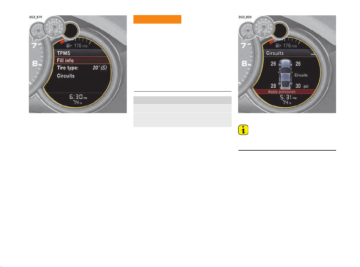
Instrument Panel and Multi-Function Display 91
Selecting “Circuits” in the TPMS menu
For driving on a race circuit, you can set and
monitor pressures different to those used for road
mode.
Race circuit mode is not designed for driving on
public roads.
This gives the experienced driver the option of
customising tire pressure to suit race circuits, for
optimum handling.
The driver remains responsible when driving, e.g.
setting tire pressures for driving on race circuits,
regardless of Tire Pressure Monitoring System.
f Adjust the required pressure to suit the
maximum intended driving speeds.
Take into account the warning thresholds
which trigger a tire pressure warning.
For information on warning thresholds and tire
pressure warnings:
f Please see the chapter “TIRE PRESSURE
WARNINGS” on page 93.
The current actual tire pressures are displayed.
Setting tire pressure for race circuits
Information
The desired actual tire pressures must not be less
than 26 psi (1.8 bar) at each wheel.
f Set the desired actual tire pressure for race
circuits at the wheel.
The actual tire pressures are updated in the
“Circuits” display every 5 seconds for a
maximum of 15 minutes
Low Tire Pressure
1. Main menu “TPMS”
2. Confirm “TPMS”.
3. Select “Circuits”
and confirm.
WARNING
h
92 Instrument Panel and Multi-Function Display
Information
If the tir
e pressure falls below minimum pressure,
the message “Note min. pressure 26 psi
(1.8 bar)” appears and the new pressures are not
accepted. If this is the case, the required tire
pressures must be set again.
The new tire pressures have only been accepted
successfully when the message “New target
pressures” appears on the multi-function display.
When race circuit mode is activated, is
displayed permanently on the multi-function
display.
Returning to road mode
There are two options for returning to road mode.
Option 1
without switching off the ignition
If you change from race circuit mode to road
mode without first switching off the ignition, the
previous tire selection continues to be monitored.
f Use the pressure differences shown in the “Fill
info” display in the “TPMS” main menu or from
the corresponding tire pressure warning when
correcting the tire pressure.
Option 2
after switching off the ignition
When race circuit mode is activated, the
“Circuits” screen appears on the multi-function
display whenever the ignition is switched on,
together with the prompt (selection): “No”/“Yes”/
“New pressure”.
–“No”:
If you select “No” and then select the
“Tire type” menu, the required tire pressures
will be set back to road mode.
Tire Pressure Monitoring System will relearn the
wheels once you have returned to road mode.
During this process the required pressures for
cold tires (20 °C) are shown under “Fill info” in the
“TPMS” main menu.
f Please see the chapter “SYSTEM LEARNING”
on page 90.
f Once the Tire Pressure Monitoring System has
finished learning, check the tire pressure for all
wheels under “Fill info”.
f Correct the tire pressure to the required
pressure if necessary (differential pressure
value “0.0”).
–“Yes ”:
If you select “Ye s ”, this inserts the required tire
pressures that you set for driving on a race
circuit.
–“New pressure”:
If you select “New pressure”, you can set new
required tire pressures for driving on a race
circuit.
Information
If you make no selection before driving off, the
system automatically switches back to road mode
and the message “Tire change? Update
settings” appears.
f Update the multi-function display settings the
next time the vehicle is stationary.
1. Main menu “TPMS”
> “TPMS”
> “Circuits”
2. Select “Apply pressures”
and confirm.
1. Main menu “TPMS”
> “TPMS”
> “Circuits”
2. Select “No” and confirm.
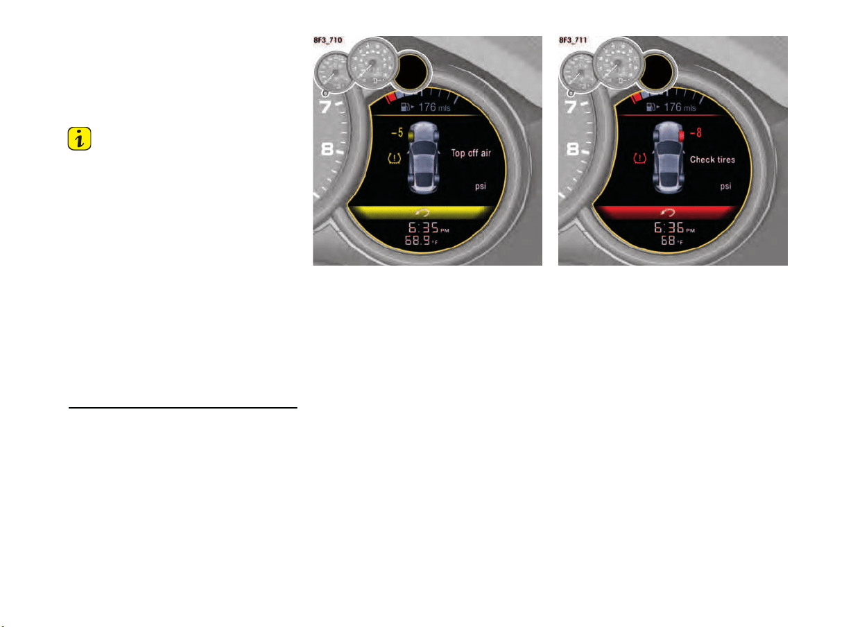
Instrument Panel and Multi-Function Display 93
Tire pressure warnings
The tire pressure warning light on the instrument
panel and a corresponding message on the multi-
function display warn about loss of pressure in two
stages (yellow and red), depending on the amount
of pressure loss.
Information
Race circuit mode:
– If the actual tire pressure falls below 23 psi
(1.6 bar) (e.g. due to cooling), a red warning is
issued.
The red warning stops as soon as actual tire
pressure is above 23 psi (1.6 bar) (e.g. due to
warming).
– If the pressure also falls below the warning
threshold, the warning only stops when the
tires are filled to the required pressure again
(differential pressure value “0.0”) or
a new required pressure is set in the
“Circuits” menu.
For information on warning thresholds:
f Please see the chapter “RED WARNING –
“Check tires”” on page 93. Always check for
damage before filling the tires to the required
pressure (differential pressure value “0.0”).
Yellow warning – “Top off air“
The pressure in the tire is too low by more than
4 to 7 psi/0.3 to 0.5 bar/30 to 50 kPa. The
tire pressure warning specifies the affected tire
and the target tire pressure.
f Fill up with air at the next opportunity.
This tire pressure warning appears:
– for approx. 10 seconds when the vehicle is
stationary and the ignition is switched off or
– when the ignition is switched on again.
The warning can be acknowledged when the
ignition is switched on.
The tire pressure warning light on the instrument
panel goes out only when the tire pressure has
been corrected (differential pressure value “0.0”).
Red warning – “Check tires”
At speeds below 100 mph (160 km/h):
– The pressure in the tire has dropped by 20 %
below the required pressure or by more
than 7 psi/0.5 bar/50 kPa. This significant
pressure loss is a danger to road safety.
At speeds above 100 mph (160 km/h):
– The pressure in the tire has dropped by more
than 6 psi/0.4 bar/40 kPa. This significant
pressure loss is a danger to road safety.
f When the tire pressure warning appears, stop
immediately at a suitable location. Check the
indicated tire for signs of damage. If
necessary, fill in tire sealant and set the
correct tire pressure.
This tire pressure warning also appears when
driving and can be acknowledged.
The tire pressure warning light on the instrument
panel goes out only when the tire pressure has
been corrected (differential pressure value “0.0”).
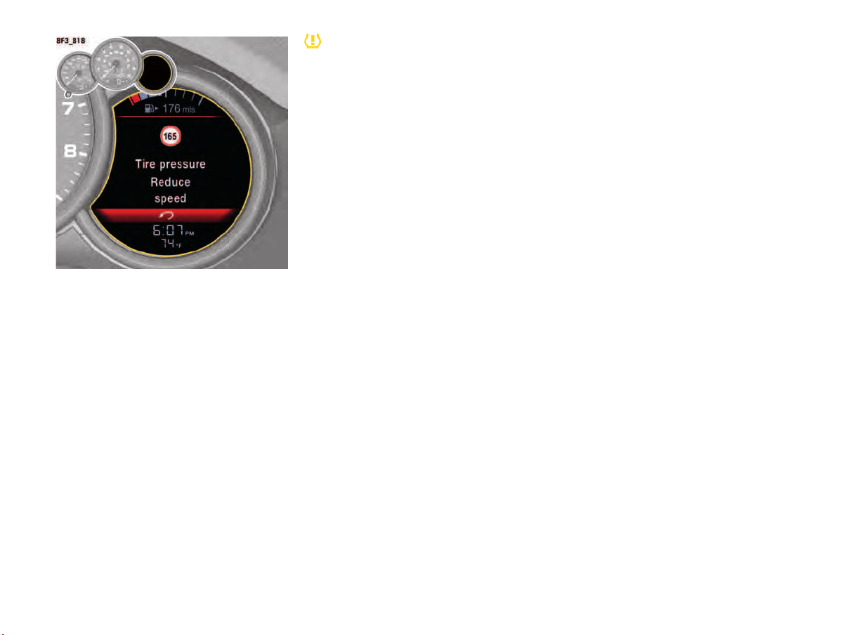
94 Instrument Panel and Multi-Function Display
Speed warning - “Tire pressure Reduce
speed“
At speeds above 165 mph (270 km/h):
–
The pressure in the tire has dropped by more
than 4 psi/0.3 bar/30 kPa. This pressure
loss is a danger to road safety.
f When the tire pressure warning appears,
reduce speed to below 165 mph (270 km/h)
until the warning disappears.
When driving at very high speeds, increase the
tire pressure to the required pressure
(differential pressure value “0.0”).
For information on tire sealing compound:
f Please see the chapter “FILLING IN SEALANT”
on page 200.
Warning light
The warning light in the instrument panel lights up:
– When a loss in pressure has been detected.
– In the event of a defect in Tire Pressure
Monitoring System or a temporary fault.
– When learning new fitted wheels/wheel
transmitters, as long as the vehicle’s own
wheels have not yet been recognized.
A warning message also appears on the multi-
function display in the instrument panel.
f Please see the chapter “OVERVIEW OF
WARNING AND INFORMATION MESSAGES”
on page 109.
The tire pressure warning light on the instrument
panel goes out only when the cause of the fault
has been rectified.
Changing a wheel and replacing tires
f New wheels must be fitted with radio
transmitters for Tire Pressure Monitoring
System.
Before tires are changed, the battery charge
condition of the wheel transmitters should be
checked.
We recommend that you get an authorized
Porsche dealer to do this work as they have
trained workshop personnel and the necessary
parts and tools.
f Switch off the ignition when changing a wheel.
The tire settings on the multi-function display must
be updated after changing a wheel.
If the tire settings are not updated, the message
“Tire change? Update settings” is displayed on
the multi-function display.
f Update the multi-function display settings the
next time the vehicle is stationary.
Pressure increase as the result of
temperature increase
In accordance with physical principles, the tire
pressure changes as the temperature changes.
For every 18 °F (10 °C) change in temperature,
the tire pressure increases or decreases by
approx. 1.5 psi (0.1 bar/10 kPa).
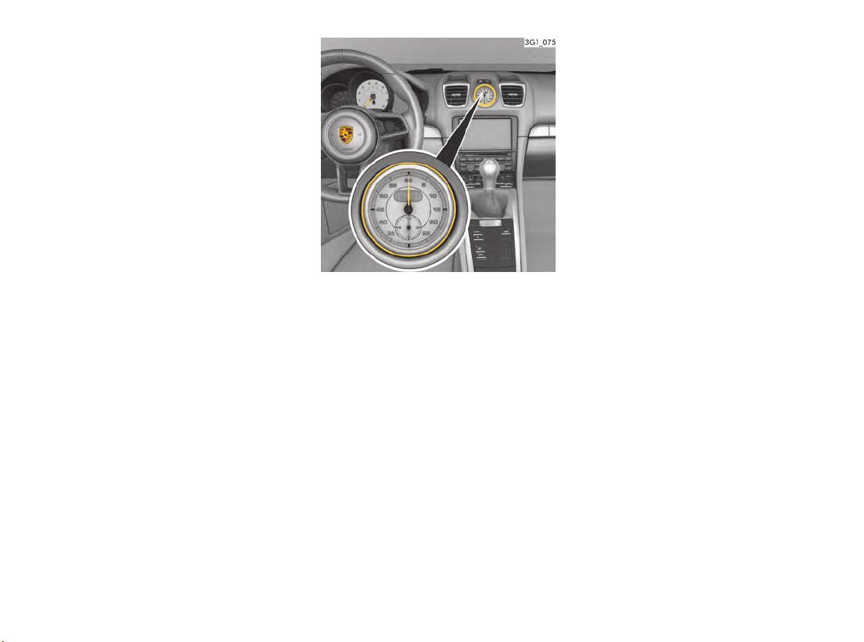
Instrument Panel and Multi-Function Display 95
Partial monitoring
Monitoring of the other wheels is continued if there
is a fault in one or two wheel transmitters.
– The tire pressure warning light lights up.
– The message “Restricted monitoring”
appears on the multi-function display.
– No tire pressures are displayed on the
multi-function display for wheels with faulty
wheel transmitters.
No monitoring
In the event of faults, Tire Pressure Monitoring
System cannot monitor the tire pressure.
The warning light on the instrument panel lights up
and a corresponding message appears on the
multi-function display.
Monitoring is not active:
– If Tire Pressure Monitoring System is faulty.
– If wheel transmitters for Tire Pressure
Monitoring System are missing.
– During the learning phase after the tire settings
have been updated.
– After a wheel change without updating the tire
settings.
– If more than four wheel transmitters are
recognized.
– If there is external interference by other radio
sources, e.g. wireless headphones.
– If tire temperatures are too high.
f Please see the chapter “OVERVIEW OF
WARNING AND INFORMATION MESSAGES”
on page 109.
Chrono Menu (Stopwatch)
You can use the stopwatch to measure any times,
e.g. on the race circuit or on work-related
journeys. Measured lap times can be stored and
evaluated if the vehicle is equipped with Porsche
Communication Management (PCM).
f Please observe the chapter “SPORT DISPLAY”
in the separate PCM operating instructions.
Driving data can be displayed, recorded and
analysed on a smartphone using the Porsche
Track Precision app (country-dependent).
f Please see the chapter “PORSCHE TRACK
PRECISION APP” on page 129.
Automatic lap counting and timing are possible
using the lap trigger available as an option via
Porsche Tequipment.
f Please see the chapter “LAP TRIGGER”
on page 130.
Stopwatch on the dashboard
The stopwatch has an analoge and a digital
display.
The large pointer of the analog display measures
the seconds. The two small pointers measure
hours and minutes. The display re-starts at zero
after 12 hours.
Seconds and increments of
1/10th and 1/100th of a second can be read on
the digital display.
The digital display and the multi-function display
can show up to 99 hours and 59 minutes.
Stopwatch timing displays
The stopwatch time is displayed at different
positions on the dashboard:
– In the stopwatch on the dashboard.
– In the “Chrono” menu in the multi-function
display on the instrument panel.
– In the “CAR” main menu on the PCM.
Displaying the time on the stopwatch
You can configure the stopwatch on the
dashboard to display the time in the multi-function
display on the instrument panel.
For information on displaying the time on the
stopwatch:
f Please see the chapter “DISPLAYING TIME IN
STOPWATCH ON DASHBOARD” on page 107.
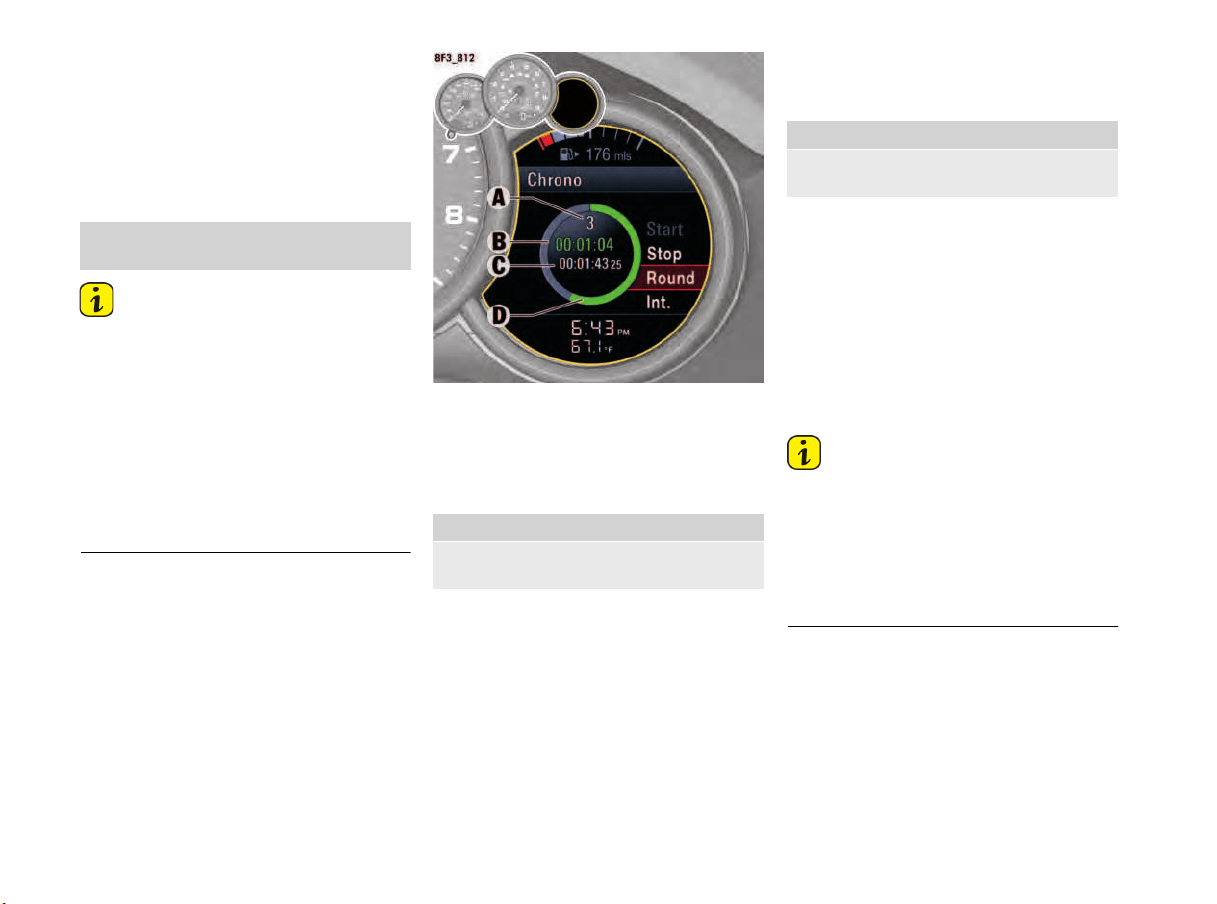
96 Instrument Panel and Multi-Function Display
Chrono on multi-function display
All stopwatch displays are started and stopped in
the “Chrono” menu on the multi-function display.
For instructions on using the multi-function
display:
f Please see the chapter “OPERATING THE
MULTI-FUNCTION DISPLAY ON THE
INSTRUMENT PANEL” on page 78.
Information
If you exit the “Chrono” menu while the stopwatch
is running, measurement will continue.
The stopwatch stops after the ignition is switched
off. If the ignition is switched on again within
approx. 4 minutes, the stopwatch will continue to
run.
The only way to reset the stopwatch to zero is by
selecting “Reset” in the “Chrono” menu.
For information on resetting the stopwatch:
f Please see the chapter “RESETTING THE
STOPWATCH TIME” on page 97.
A - Number of completed laps
B - Current stopwatch time
C - Reference time (fastest lap)
D - Circle display: Comparison of current lap time
with the reference time
Starting timing
The stopwatch time B is displayed simultaneously
on all stopwatch displays in the vehicle.
Stopping lap/Starting new lap
The current stopwatch time can be stored as a lap
time while the stopwatch is still running.
The lap counter value A is incremented by the
value of 1.
The time of the fastest completed lap is stored
temporarily as a reference value C.
The stopwatch time B and the circle display D turn
a different color to indicate whether the current
lap time is quicker than, slower than or identical to
the current fastest lap.
– Green: Current lap time is faster.
– Yellow: Current lap time is identical.
– Red: Current lap time is slower.
Information
If a reference time has not been stored yet, the
reference time position C remains blank.
The segment display is not colored.
A maximum of 63 laps can be stored during each
session.
The current stopwatch time B and the display D
are only highlighted in colour when driving.
1. Main menu: Select “Chrono”
and confirm.
1. Main menu “Chrono”
2. Select “Start”
and confirm.
1. Main menu “Chrono”
2. Select “Round”
and confirm.
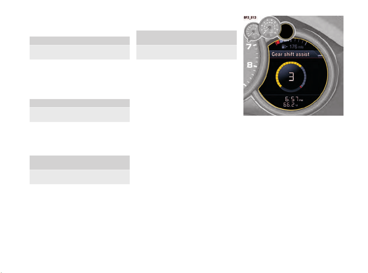
Instrument Panel and Multi-Function Display 97
Storing intermediate time
You can store an intermediate time while the
stopwatch is still running.
The intermediate time is displayed temporarily on
the multi-function display. It is not stored.
Timing continues in the background.
Stopping timing
You can stop the stopwatch at any time.
The stopwatch time B stops.
Continuing timing
You can resume timing again after stopping the
stopwatch.
The stopwatch time B continues.
Resetting the stopwatch time
The stopwatch time can be reset to zero.
All stopwatch time displays are reset to zero.
Gear Shift Assist Menu
(in vehicles with manual transmission)
In order to provide assistance during
performance-oriented driving, a graphic display of
the upshift indicator is shown in the “Gear shift
assist” main menu.
The gearshift assistant displays a prompt to shift
to the next-higher gear with a pre-indication via
segments that fill up. The sequence in which the
segments are filled with color is white, yellow,
red.
1. Main menu “Chrono”
2. Select “Interim”
and confirm.
1. Main menu “Chrono”
2. Select “Stop”
and confirm.
1. Main menu “Chrono”
> “Stop”
2. Select “Cont.”
and confirm.
1. Main menu “Chrono”
> “Stop”
2. Select “Reset”
and confirm.
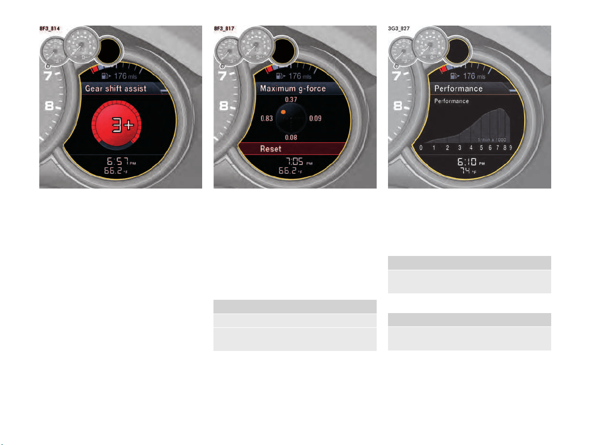
98 Instrument Panel and Multi-Function Display
When all the segments are filled in red, a “+” sign
appears next to the engaged gear in the display as
a pr
ompt to shift to the next-higher gear.
G-Forces Menu
In the “G-forces” main menu, the current lateral
and longitudinal acceleration forces are shown
graphically (in m/s
2
) in the form of a circular
diagram.
The maximum occurring longitudinal and lateral
acceleration forces are displayed (in m/s
2
) in the
“Maximum g-force” sub-menu.
The values can be reset via the menu item “Reset”
(illustration).
Performance Menu
In the “Performance” main menu, the current
power or torque can be displayed graphically as a
function of engine speed.
Power
Torque
1. “G-forces” main menu
2. Confirm “Maximum g-force”.
3. Select “Reset”
and confirm.
1. Main menu “Performance”
2. Select “Performance”
and confirm.
1. Main menu “Performance”
2. Select “Torque”
and confirm.

Instrument Panel and Multi-Function Display 99
Vehicle Settings on the
Multi-Function Display
Different settings can be adjusted in the multi-
function display on the instrument panel
depending on the vehicle equipment.
Selecting settings menu
Selecting setting options or activating
vehicle functions
A symbol positioned in front of a setting option
indicates whether the option is selected or a
vehicle function is activated.
Selecting one of several options
Option is selected.
Option is not selected.
Activating and deactivating functions
Function is activated.
Function is deactivated.
Resetting to factory settings
All settings made in the multi-function display can
be reset to the factory settings:
Information
All personal settings that have already been stored
will be lost as a result of resetting to factory
settings.
Adapting appearance of multi-function
display
The contents and appearance of the multi-function
display can be adapted individually.
Selecting main menu display contents
Individual elements in the main menu can be
hidden and shown as required.
The main menu items “Audio”, “Phone”, “Map”,
“Navigation”, “Trip”, “TPMS”, “Chrono”,
“Gearshift assist” and “G-Force“ can be hidden
or shown.
The menu items “Vehicle” cannot be hidden.
Adapting display contents of audio main
menu
In the audio main menu, you can display either a
list of all radio stations currently within range or a
list of all stored radio stations.
Available display contents:
–“Station list”
List of stations currently within range.
–“Preset list”
List of stored stations.
Adapting display contents in vehicle
information area
You can select four of the many items of vehicle
information for display in the “Vehicle” menu and
assignment to the display areas 1, 2, 3 and 4.
1. Main menu: Select “Vehicle”
> “Settings”
and confirm
1. Main menu “Vehicle”
> “Settings”
2. Select “Fact. settings”
and confirm.
3. Select “Ye s ”
and confirm.
1. Main menu: Select “Vehicle”
> “Settings”
> “Display”
and confirm.
1. Main menu “Vehicle”
> “Settings”
> “Display”
2. Select “Menu scope”
and confirm.
3. Select the desired main menu item.
4. Confirm your selection.
Menu item is displayed.
Menu item is hidden.
1. Main menu “Vehicle”
> “Settings”
> “Display”
2. Select “Audio”
and confirm.
3. Select the desired display contents
and confirm.
1. Main menu “Vehicle”
> “Settings”
> “Display”
2. Select “Vehicle menu”
and confirm.

100 Instrument Panel and Multi-Function Display
Available display contents:
–“V
eh. voltage”
–“Oil pressure”
–“Oil temperature”
–“Coolant temp.” – Coolant temperature
–“Fuel Range”
–“Dst: Arrival” – Arrival time at destination
–“Int: Arrival” – Arrival time at intermediate
destination
“Dst: Trip time” – Driving time to destination
–“Int: Trip time” – Driving time to intermediate
destination
–“Compass”
–“GPS height”
–“Time”
–“Date”.
–“Station/Track” – Current radio station/
music track
–“Phone info” – Network strength/network
name
–“Blank line” – Line remains empty
Information
One item of vehicle information cannot be
assigned to several display areas.
Example configuration of multi-function display
information area
A - Coolant temperature gauge
B - Engine oil temperature gauge
C - Engine oil pressure gauge
A – Coolant temperature gauge
If the cooling system is in any way faulty, consult
an authorized Porsche dealer.
Bar in left area – engine cold
f Avoid high engine speeds and heavy engine
loading.
Bar in center area – normal operating
temperature
The bar may move up to the red area when the
engine is under heavy load and the outside
temperature is high.
Coolant temperature warning
If the coolant temperature is too high, the
temperature gauge moves to the maximum mark
and the warning message “Engine too hot Park
vehicle to cool down” appears on the multi-
function display in the instrument panel.
f Switch the engine off and let it cool.
f Check radiators and air guides in front end of
vehicle for obstructions.
f Check the coolant level.
Top up with coolant if necessary.
f Have the fault corrected.
f Please see the chapter “CHECKING THE
COOLANT LEVEL AND ADDING COOLANT”
on page 184.
f Please see the chapter “OVERVIEW OF
WARNING AND INFORMATION MESSAGES”
on page 109.
Information
To prevent excessive temperatures, the cooling
air ducts must not be obstructed by covering
them (e.g. with film, “stone guards“, etc.).
Coolant level warning
At engine temperatures below 140 °F (60 °C):
A low coolant level is indicated by the warning
message “Refill coolant Observe engine
temperature” on the multi-function display in the
instrument panel.
f Add coolant.
At engine temperatures above 140 °F (60 °C):
A low coolant level is indicated by the warning
message “Refill coolant immediately
Do not drive on” on the multi-function display in
the instrument panel. The temperature gauge
moves to the maximum mark.
f Switch engine off and let it cool.
3. Select
“Field 1:” or
“Field 2:” or
“Field 3:” or
“Field 4:”
and confirm.
4. Select the desired display contents
and confirm.

Instrument Panel and Multi-Function Display 101
f Add coolant.
If the coolant level is low, warning indicators may
light up if the vehicle tilts at an extreme angle (e.g.
steep slopes) or generates high lateral
acceleration while travelling round long bends
(e.g. driving in circles). If the warnings do not
disappear once the vehicle has assumed “normal”
operating state, check the coolant level.
f Please see the chapter “CHECKING THE
COOLANT LEVEL AND ADDING COOLANT”
on page 184.
f Please see the chapter “OVERVIEW OF
WARNING AND INFORMATION MESSAGES”
on page 109.
Risk of engine damage.
f Do not continue driving if the warning persists
even when the engine coolant level is correct.
f Have the fault corrected.
We recommend that you get an authorized
Porsche dealer to do this work as they have
trained workshop personnel and the necessary
parts and tools.
B – Engine oil temperature gauge
A warning message will appear on the multi-
function display in the instrument panel if the
engine oil temperature is too high.
f Reduce engine speed and engine load
immediately if the red zone is reached.
For information on warning messages on the multi-
function display:
Please see the chapter “OVERVIEW OF WARNING
AND INFORMATION MESSAGES” on page 109.
C – Engine oil pressure gauge
The oil pressure is controlled as required and
should be at least 51 psi (3.5 bar) at an engine
speed of 5,000 rpm.
The engine oil pressure varies depending on the
engine speed, oil temperature and engine load.
If oil pressure drops abruptly and a message
is displayed on the multi-function display
when the engine is running or while driving:
f Stop immediately in a suitable place.
f Switch off the engine.
f Check whether there is an obvious oil leak on
or under the car.
f Select “Oil level” on the multi-function display.
f Please see the chapter “DISPLAY AND
MEASUREMENT OF THE ENGINE OIL LEVEL”
on page 82.
f Add engine oil if necessary.
Risk of engine damage.
f Do not continue driving if there is an obvious oil
leak.
f Do not continue driving if the warning message
appears even when the oil level is correct.
f Have the fault corrected.
We recommend that you get an authorized
Porsche dealer to do this work as they have
trained workshop personnel and the necessary
parts and tools.
Displaying PCM information on the multi-
function display
You can configure the multi-function display to
temporarily display different items of information
relating to Porsche Communication Management
(PCM).
Available PCM information:
–“Map info”
Navigation map appears automatically when
navigation information is available.
–“Phone info”
Information on incoming and outgoing calls is
displayed.
–“Voice control”
Help text appears when the voice control
button is pressed.
–“Arrow info”
Navigation arrow appears automatically when
navigation information is available.
NOTICE
NOTICE
1. Main menu “Vehicle”
> “Settings”
> “Display”
2. Select “PCM display”
and confirm.
3. Select desired PCM
information.
4. Confirm your selection.
Information is displayed.
Information is not displayed.

102 Instrument Panel and Multi-Function Display
Adapting fuel gauge
The fuel range can be shown or hidden on the fuel
gauge (upper line).
Available display content:
–“Fuel Range”
Adapting status ar
ea
You can assign the current time and/or outside
temperature to the status area in the multi-function
display.
Available display contents:
–“Time”
–“Temperature”
–“Time & Temp.”
Adjusting display brightness
The brightness of the multi-function display can be
adjusted to suit individual requirements.
Light and visibility settings
The exterior lights, interior lighting and visual aids
for reversing the vehicle can be adapted
individually.
Adjusting exterior lights
You can adapt the exterior light functions on the
vehicle e.g. the dynamic high beam and off delays
of the Welcome Home and Entry functions in the
“Exterior lights” menu.
Adjusting off delay for Welcome Home and
Entry functions
The off delay of the Welcome Home and Entry
functions can be adapted individually.
1. Main menu “Vehicle”
> “Settings”
> “Display”
2. Select “Upper line”
and confirm.
3. Select display
contents and confirm.
1. Main menu “Vehicle”
> “Settings”
> “Display”
2. Select “Lower line”
and confirm.
3. Select the desired display contents
and confirm.
1. Main menu “Vehicle”
> “Settings”
> “Display”
2. Select “Brightness”
and confirm.
3. Select the desired brightness
and confirm.
1. Main menu: Select “Vehicle”
> “Settings”
> “Light & Visibility”
and confirm.
1. Main menu: Select “Vehicle”
> “Settings”
> “Light & Visibility”
> “Exterior lights”
and confirm.
1. Main menu “Vehicle”
> “Settings”
> “Light & Visibility”
> “Exterior lights”
2. Select “Fade-out”
and confirm.
3. Select the desired off delay
and confirm.

Instrument Panel and Multi-Function Display 103
Adjusting interior lights
Interior light functions on the vehicle can be
adapted individually in the “Interior lights” menu.
Activating or deactivating interior lights
when the door is opened (depending on
equipment)
You can configure the interior lights to be switched
on when the door is opened.
Adjusting brightness of orientation lighting
The brightness of the orientation lighting can be
adapted individually.
Ambient lighting
The brightness of the ambient lighting can be
adapted individually.
Setting interior lighting off delay
The off delay for the lighting in the passenger
compartment after closing the vehicle doors can
be adapted individually.
Activating and deactivating rain sensor
operation
You can configure the windshield wiper to adjust
the wiper speed automatically when it is raining.
Available setting options:
–“Automatic”
The wiper speed is automatically adjusted.
– “Manual”
The wiper speed must be manually adjusted
using the wiper switch.
1. Main menu: Select “Vehicle”
> “Settings”
> “Light & Visibility”
> “Interior lights”
and confirm.
1. Main menu “Vehicle”
> “Settings”
> “Light & Visibility”
> “Interior lights”
2. Select
“by opening door”
3. Confirm your selection.
Interior lights are activated.
Interior lights are deactivated.
1. Main menu “Vehicle”
> “Settings”
> “Light & Visibility”
> “Interior lights”
2. Select “Orientation”
and confirm.
3. Select the desired brightness
and confirm.
1. Main menu “Vehicle”
> “Settings”
> “Light & Visibility”
> “Interior lights”
2. Select “Ambient light”
and confirm.
3. Select the desired brightness
and confirm.
1. Main menu “Vehicle”
> “Settings”
> “Light & Visibility”
> “Interior lights”
2. Select “Fade-out”
and confirm.
3. Select the desired off delay
and confirm.
1. Main menu “Vehicle”
> “Settings”
> “Light & Visibility”
> “Wiper”
2. Select “Rain sensor”
and confirm.
3. Select the desired setting
and confirm.

104 Instrument Panel and Multi-Function Display
Locking settings
The locking and unlocking settings on the vehicle
can be adjusted.
The Easy Entry function can be switched on and
of
f.
Setting door unlocking
You can configure specific doors to unlock when
the vehicle is unlocked.
Available setting options:
–“All doors”
All doors are unlocked when the vehicle is
unlocked.
–“Driver’s door”
The driver’s door is unlocked when the vehicle
is unlocked.
Setting door locking
You can configure the doors to remain unlocked or
lock automatically after a delay on entering the
vehicle.
Available setting options:
–“Off”
The doors are not locked automatically after
entering the vehicle.
–“After ign. on”
The doors are locked automatically when the
ignition is switched on.
–“After drive-off”
The doors are locked automatically after
driving off.
Switching Comfort Entry on and off
You can configure the driver’s seat and steering
wheel to move back automatically and allow the
driver to get in and out of the vehicle more easily.
Setting air conditioning
(on vehicles with 2-zone air conditioning)
The automatic air conditioning can be changed
individually.
Adjusting air flow
The strength of the air flow and the air quantity can
be adjusted.
Available setting options:
–“Soft”
–“Normal”
–“Strong”
1. Main menu: Select “Vehicle”
> “Settings”
> “Locking”
and confirm.
1. Main menu “Vehicle”
> “Settings”
> “Locking”
2. Select “Door unlock”
and confirm.
3. Select the desired setting
and confirm.
1. Main menu “Vehicle”
> “Settings”
> “Locking”
2. Select “Door lock”
and confirm.
3. Select the desired setting
and confirm.
1. Main menu “Vehicle”
> “Settings”
> “Locking”
2. Select
“Comfort Entry”.
3. Confirm your selection.
Comfort Entry is activated.
Comfort Entry is deactivated.
1. Main menu: Select “Vehicle”
> “Settings”
> “Air conditioning”
and confirm.
1. Main menu “Vehicle”
> “Settings”
> “Air conditioning”
2. Select “Air flow”
and confirm.
3. Select the desired setting
and confirm.

Instrument Panel and Multi-Function Display 105
Switching extended ventilation panel
on and off
The extended ventilation panel on top of the
dashboard can be switched on or off.
Switching automatic air-recirculation mode
on/off
You can configure the fresh air supply to adjust
automatically to the air quality.
Setting date and time
The date and time displays on the vehicle can be
adjusted individually.
Information
On vehicles with Porsche Communication
Management (PCM), the date and time are set and
synchronised automatically by satellite navigation
signals (GPS).
Some setting options may be temporarily
unavailable, depending on satellite signal
reception.
Setting the time
The time, time format and time zone can be set in
the “Time” menu.
Displaying GPS time
The time can be synchronised via the GPS signal
and displayed.
Setting the time format
The time can be displayed in 12-hour or 24-hour
format.
Available setting options:
–“12h”
–“24h”
1. Main menu “Vehicle”
> “Settings”
> “Air conditioning”
2. Select
“Vent. panel”.
3. Confirm your selection.
Ventilation panel is activated.
Ventilation panel is deactivated.
1. Main menu “Vehicle”
> “Settings”
> “Air conditioning”
2. Select
“Auto air circ.“.
3. Confirm your selection.
Automatic air-recirculation mode
is activated
Automatic air-recirculation mode
is deactivated
1. Main menu: Select “Vehicle”
> “Settings”
> “Date & Time”
and confirm.
1. Main menu: Select “Vehicle”
> “Settings”
> “Date & Time”
> “Time”
and confirm.
1. Main menu “Vehicle”
> “Settings”
> “Date & Time”
> “Time”
2. Select
“GPS time”
3. Confirm your selection.
Time synchronised with GPS.
Time not synchronised with GPS.
1. Main menu “Vehicle”
> “Settings”
> “Date & Time”
> “Time”
2. Select “Format”
and confirm.
3. Select the desired setting
and confirm.

106 Instrument Panel and Multi-Function Display
Setting current time
On vehicles without Porsche Communication
Management (PCM), the hours and minutes can be
set separately when setting the time.
Setting time zone
The time zone of the vehicle clock can be set
individually on vehicles with Porsche
Communication Management (PCM).
Setting the date
The date and date format can be changed in the
“Date” menu.
Setting the date format
The date format can be adjusted.
Available setting options:
–“DD.MM.YYYY”
–“MM/DD/YYYY”
–“YYYY/MM/DD”
Setting the curr
ent date
The day, month and year can be set individually on
vehicles without the navigation module.
Setting Daylight Saving Time
The vehicle clock can be configured to change to
Daylight Saving Time (DST).
1. Main menu “Vehicle”
> “Settings”
> “Date & Time”
> “Time”
2. Select
“Hour/Minute”
3. Set the desired time
and confirm.
1. Main menu “Vehicle”
> “Settings”
> “Date & Time”
> “Time”
2. Select “Zone”
and confirm.
3. Select the desired time zone
and confirm.
1. Main menu: Select “Vehicle”
> “Settings”
> “Date & Time”
> “Date”
and confirm.
1. Main menu “Vehicle”
> “Settings”
> “Date & Time”
> “Date”
2. Select “Format”
and confirm.
3. Select the desired setting
and confirm.
1. Main menu: Select “Vehicle”
> “Settings”
> “Date & Time”
> “Date”
and confirm.
2. Select
“Date”.
3. Set the desired date
and confirm.
1. Main menu “Vehicle”
> “Settings”
> “Date & Time”
2. Select
“DST (+01:00)”
3. Confirm your selection.
Daylight Saving Time is activated.
Daylight Saving Time is deactivated.

Instrument Panel and Multi-Function Display 107
Displaying time in stopwatch on dashboard
You can configure the stopwatch on the
dashboard to display the time.
Setting units
You can select the units of measurement for
vehicle displays such as the speed on the digital
speedometer in the instrument panel, the
temperature gauge in the air-conditioning displays
and the tire pressure display on the multi-function
display.
Setting speedometer units
The units of the speed and distance information on
the speedometer can be adjusted.
Available setting options:
–“km / km/h”
–“Miles / mph”
Setting unit for temperature gauges
The measurement unit for temperature gauges
can be changed.
Available setting options:
–“°C”
–“°F”
Setting unit for Tire Pressure Monitoring
System display
The measurement unit for the Tire Pressure
Monitoring System display can be changed.
Available setting options:
–“bar”
–“psi”
Setting unit for fuel consumption display
The unit can be set for the fuel consumption
display.
Available setting options:
–“l/100km”
–“MPG (US)”
–“MPG (UK)”
–“km/l”
1. Main menu “Vehicle”
> “Settings”
> “Date & Time”
2. Select
“Time – Chrono”
3. Confirm your selection.
Time is displayed.
Time is not displayed.
1. Main menu: Select “Vehicle”
> “Settings”
> “Units”
and confirm.
1. Main menu “Vehicle”
> “Settings”
> “Units”
2. Select
“Speedometer”.
3. Select the desired setting
and confirm.
1. Main menu “Vehicle”
> “Settings”
> “Units”
2. Select
“Temperature”
3. Select the desired setting
and confirm.
1. Main menu “Vehicle”
> “Settings”
> “Units”
2. Select
“TPMS”.
3. Select the desired setting
and confirm.
1. Main menu “Vehicle”
> “Settings”
> “Units”
2. Select
“Consumpt”.
3. Select the desired setting
and confirm.

108 Instrument Panel and Multi-Function Display
Changing the language
The language of the display text on the multi-
function display can be changed.
Adjusting volume of warning and
information tones
The volume of the warning tones and ParkAssist
information tones can be adjusted.
Adjusting ParkAssist volume
The volume of the ParkAssist information tones
can be adjusted.
Available setting options:
–“Loud”
–“Medium”
–“Low”
Adjusting volume of warning tones
The volume of the warning tones can be adjusted
individually.
Available setting options:
–“Loud”
–“Medium”
–“Low”
1. Main menu “Vehicle”
> “Settings”
> “Language”
2. Select the desired language
and confirm.
1. Main menu “Vehicle”
> “Settings”
> “Volume”
2. Select
“ParkAssist”.
3. Select the desired setting
and confirm.
1. Main menu “Vehicle”
> “Settings”
> “Volume”
2. Select
“Warn. tones”.
3. Select the desired setting
and confirm.
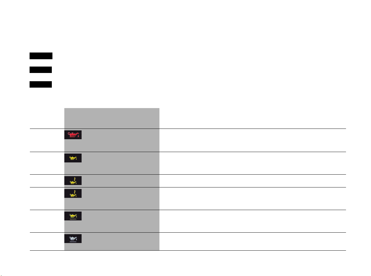
Instrument Panel and Multi-Function Display 109
Overview of Warning and Information Messages
If a warning message appears, always refer to the corresponding sections in this Owner’s Manual.
Warning messages are issued only if all measurement prerequisites are met.
Therefore, check all fluid levels regularly – in particular, always check the engine oil level before refuelling.
Warning and information message categories
f Visit or consult an authorized Porsche dealer immediately.
f Visit an authorized Porsche dealer at the next opportunity.
f Visit an authorized Porsche dealer at the next opportunity or remedy yourself.
Red System failure or warning
Yellow fault or system failure warning
White Information/message
Light in
instrument
panel
Warning and information message in the
multi-function display
Meaning/Action required
Oil press. too low
Park vehicle
safely
Stop immediately in a suitable place and switch engine off. Do not continue driving.
Select “Oil measurement” on the multi-function display. Add engine oil if necessary.
Do not continue driving if the warning message is displayed despite the oil level being correct.
Have the fault corrected at an authorized Porsche dealer.
Oil pressure
measurement fault
Driving permitted
Consult a workshop
Adapt your driving style and speed to the changed conditions.
Have the fault corrected at an authorized Porsche dealer.
Oil temperature too high
Reduce load
Switch engine off and let it cool. Check oil level and, if necessary, add oil.
Oil temperature
indicator fault
Consult a workshop
Driving permitted
Adapt your driving style and speed to the changed conditions.
Have the fault corrected at an authorized Porsche dealer.
Oil level
measurement fault
Consult a workshop
Driving permitted
Adapt your driving style and speed to the changed conditions.
Have the fault corrected at an authorized Porsche dealer.
No inform. / oil
level available
now
The oil level can be checked after waiting for approx. 1 minute with the vehicle parked on a level surface
and the engine at operating temperature. If the
rear luggage compartment lid is opened when the engine
is cold (e.g. to top up engine oil), the oil level cannot be displayed for a certain time.
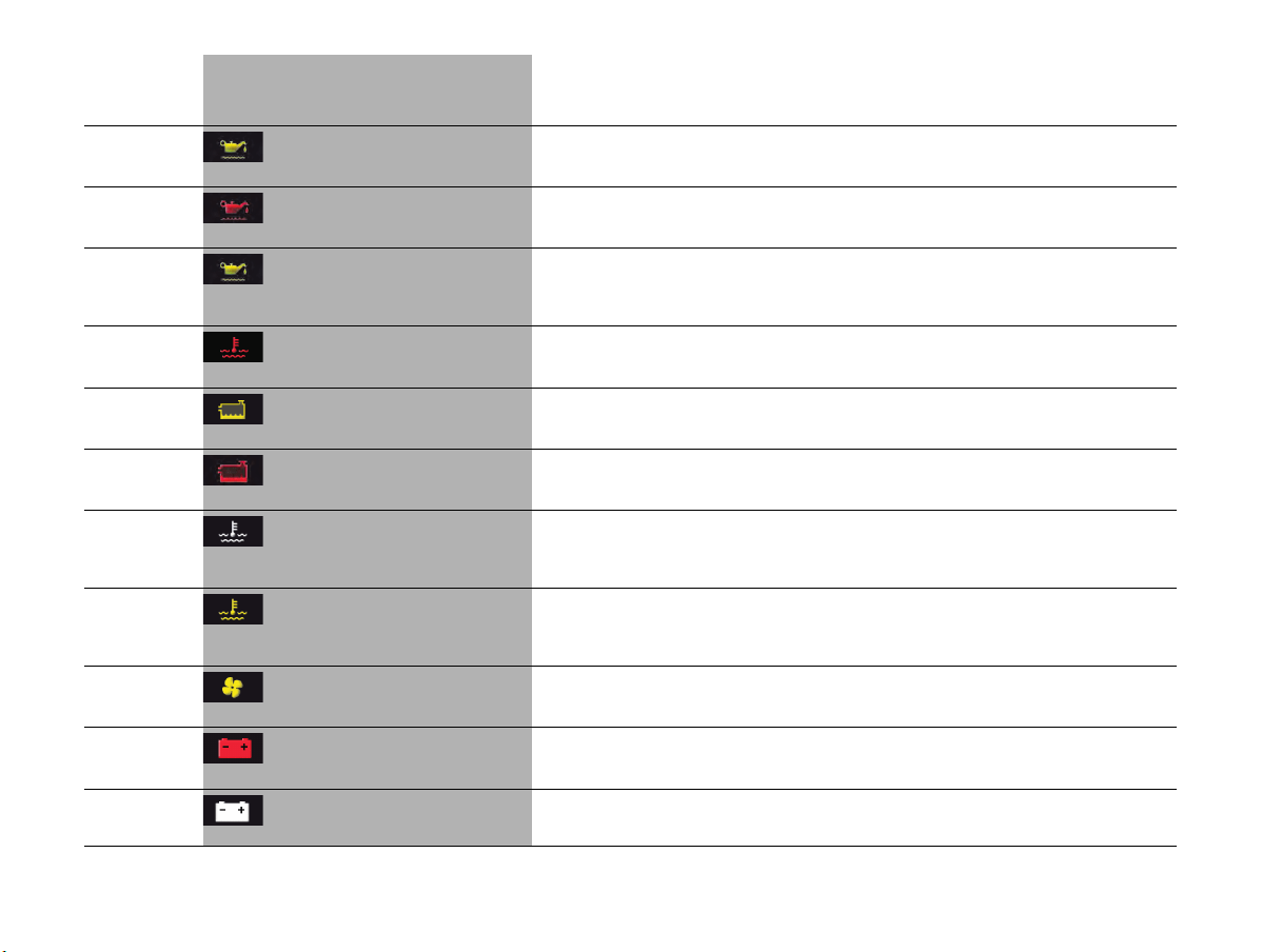
110 Instrument Panel and Multi-Function Display
Oil level minimum
reached
Refill oil
Top up engine oil immediately.
Oil level below min.
Refill oil at once
Do not drive on
Top up engine oil immediately.
Oil level
above maximum
Consult a workshop
Driving permitted
Adapt your driving style and speed to the changed conditions.
Visit an authorized Porsche dealer at the next opportunity and have the oil drained to the correct level.
Gauge moves to
maximum mark
Engine too hot
Park vehicle to cool down
Coolant or engine oil temperature is too high.
Switch off engine and let it cool.
Check coolant or engine oil level. If necessary, top up coolant / engine oil.
Refill coolant
Observe
engine temperature
Check coolant level. Add coolant if necessary.
Gauge moves to
maximum mark
Refill coolant
immediately
Do not drive on
Switch engine off and let it cool.
Check coolant level. Add coolant if necessary.
Cooling system
fault
Consult a workshop
Service required
Have the fault corrected at an authorized Porsche dealer.
Coolant temp
indicator fault
Driving permitted
Consult a workshop
Adapt your driving style and speed to the changed conditions.
Have the fault corrected at an authorized Porsche dealer.
Engine fan failure
Avoid full load
Driving permitted
Adapt your driving style and speed to the changed conditions.
Have the fault corrected at an authorized Porsche dealer.
Generator fault
Park vehicle
safely
Stop in a suitable place and switch engine off.
Do not continue driving.
Have the fault corrected at an authorized Porsche dealer.
Low battery
Start the engine and run for
extended period
Start the engine immediately so that the battery can be charged.
Light in
instrument
panel
Warning and information message in the
multi-function display
Meaning/Action required
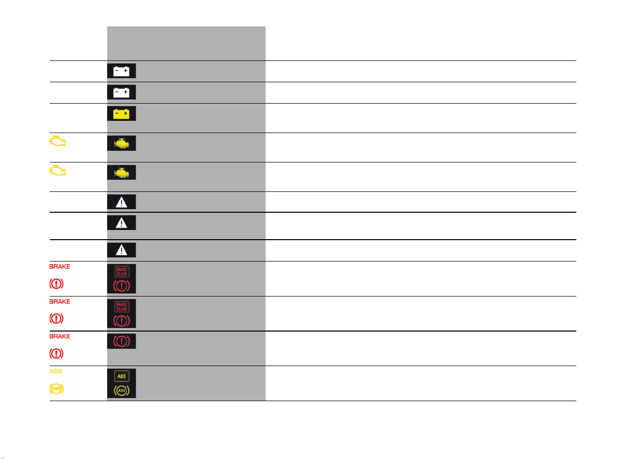
Instrument Panel and Multi-Function Display 111
Low battery
Consumption off
The power supply to various comfort features is deactivated to prevent the battery from discharging.
Battery protection was
active during parking
The power supply to various features was deactivated during parking to prevent the battery from
discharging.
Battery function
restricted
Consult a workshop
Consult an authorized Porsche dealer.
Reduced power
Driving permitted
Consult a workshop
Adapt your driving style and speed to the changed conditions.
Consult an authorized Porsche dealer.
Engine control fault
Consult a workshop
Driving permitted
Adapt your driving style and speed to the changed conditions.
Have the fault corrected at an authorized Porsche dealer.
Please start engine manually Start engine manually at the ignition.
Please
switch off
the ignition
To prevent the battery from discharging, switch off the ignition when leaving the vehicle after the engine
was stopped automatically.
Press clutch Manual transmission:
Depress clutch pedal when starting.
Brake fluid level
Park vehicle
safely
Stop immediately in a suitable place. Do not continue driving.
Have the fault corrected at an authorized Porsche dealer.
Brake distribution fault
Park vehicle safely
Stop immediately in a suitable place. Do not continue driving.
Have the fault corrected at an authorized Porsche dealer.
Brake cooling faulty Brake temperature too high.
Stop the vehicle at a suitable place, switch off engine and allow the brake to cool down.
Have the fault corrected at an authorized Porsche dealer.
ABS/PSM failure
Adapted driving permitted
Adapt your driving style and speed to the changed conditions.
Have the fault corrected at an authorized Porsche dealer.
Light in
instrument
panel
Warning and information message in the
multi-function display
Meaning/Action required
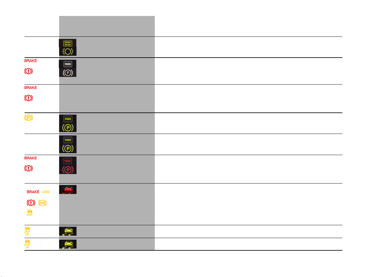
112 Instrument Panel and Multi-Function Display
Wear limit
Change brake pads
Driving permitted
Have brake pads replaced immediately.
Adapt your driving style and speed to the changed conditions.
Consult an authorized Porsche dealer.
flashes
Release
parking brake
Pull the electric parking brake switch.
Press brake pedal Press the brake pedal before releasing the electric parking brake.
Fault
parking brake
Have the fault corrected at an authorized Porsche dealer.
Electric
parking brake in
service mode
Have the fault corrected at an authorized Porsche dealer.
flashes
Emergency braking Emergency braking function of the electric parking brake active.
PSM system error
Park
vehicle safely
Stop the vehicle in a suitable place.
Do not continue driving.
Have the fault corrected immediately at an authorized Porsche dealer.
ESC + TC failure
Adapted driving permitted
Adapt your driving style and speed to the changed conditions.
Have the fault corrected at an authorized Porsche dealer.
ESC switched off Electronic Stability Control (ESC) switched off.
Light in
instrument
panel
Warning and information message in the
multi-function display
Meaning/Action required
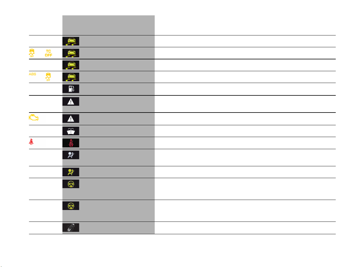
Instrument Panel and Multi-Function Display 113
ESC switched on Electronic Stability Control (ESC) switched on.
and
ESC + TC switched off Electronic Stability Control (ESC) and Traction Control (TC) switched off.
ESC + TC switched on Electronic Stability Control (ESC) and Traction Control (TC) switched on.
Roll mode active Roll mode is switched on.
Fuel gauge
warning light on
Mind remaining distance Refuel at the next opportunity.
Fault
tank display
service necessary
Have the fault corrected at an authorized Porsche dealer.
Check
tank cap
Position tank cap correctly and screw on until it locks securely.
Refill washer fluid
Fasten seat belt All vehicle occupants must fasten their safety belts.
Loss of airbag
Pilot lamp
Service required
Have the fault corrected at an authorized Porsche dealer.
Passenger airbag
on/off
The passenger airbag is switched on/off.
Power steering fail.
Increased
effort
Driving permitted
Adapt your driving style and speed to the changed conditions.
Have the fault corrected at an authorized Porsche dealer.
Power steering
restricted
Consult a workshop
Driving permitted
Steering assistance is temporarily reduced.
Adapt your driving style and speed to the changed conditions.
Consult an authorized Porsche dealer.
Remove key
from ignition
Light in
instrument
panel
Warning and information message in the
multi-function display
Meaning/Action required
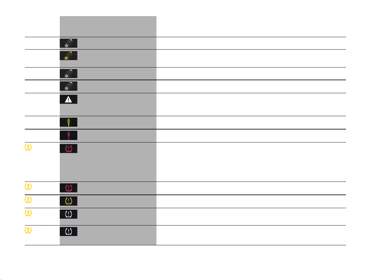
114 Instrument Panel and Multi-Function Display
Remove key from trunk
Key not found /
Key malfunction
Change key position
Make sure that you have the driver's key with you.
Replace ignition key battery Replace the battery in the driver's key.
Multiple keys recognized in
vehicle
Information message:
Several driver's keys in the vehicle, e.g. in the possession of a passenger.
PADM
deactivated
Service required
Driving permitted
Have the fault corrected at an authorized Porsche dealer.
Chassis system fault
Adapted driving permitted
Vehicle handling may be affected. Adapt your driving style and speed to the changed conditions.
Have the fault corrected at an authorized Porsche dealer.
Chassis system failure Stop immediately in a suitable place. Do not drive off or continue driving.
Have the fault corrected at an authorized Porsche dealer.
Check tires
Tire Pressure Monitoring System detects a pressure loss of more than 20% below the required pressure
or more than 7 psi (0.5 bar) at a speed of less than 100 mph (160 km/h), more than 6 psi (0.4 bar) at
a speed greater than 100 mph (160 km/h) and more than 4 psi (0.3 bar) at a speed greater than
165 mph (270 km/h).
Stop in a suitable place and check the tires indicated for damage.
If necessary, fill in tire sealant and set the correct tire pressure.
Note min. pressure 26 psi
(1.8 bar)
Tires have fallen below the minimum required pressure. For driving on race circuits,
adjust tire pressures to at least 26 psi/1.8 bar/180 kPa at each wheel.
Top off air Tire Pressure Monitoring System detects a pressure loss of more than 4 psi (0.3 bar).
Correct the tire pressure at the next opportunity.
Restricted monitoring Fault on one or both wheel transmitters.
Have the fault corrected at an authorized Porsche dealer.
No tire pressure monitoring
System is learning
Tire Pressure Monitoring System requires a certain amount of time to learn the wheels.
During this time, the current tire pressures are not available on the multi-function display.
Light in
instrument
panel
Warning and information message in the
multi-function display
Meaning/Action required
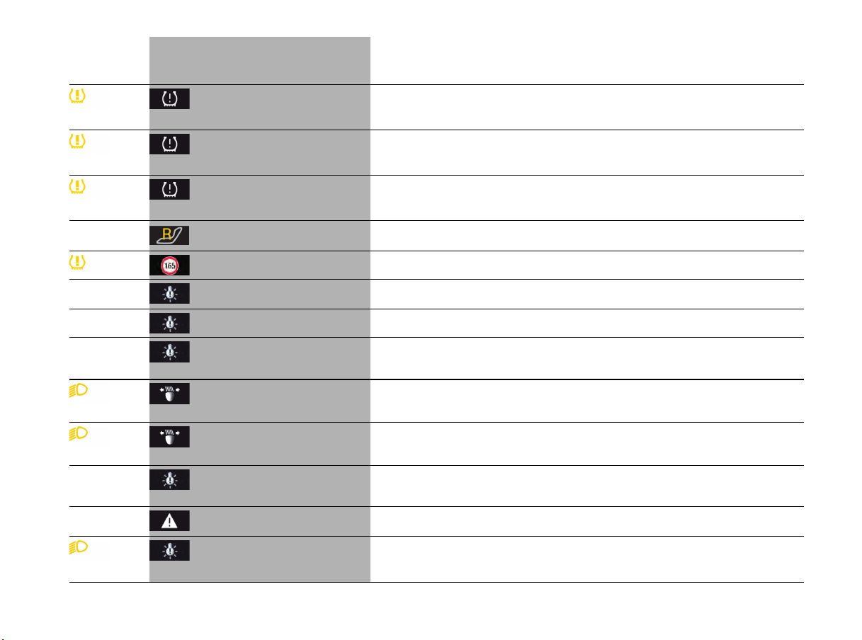
Instrument Panel and Multi-Function Display 115
Tire pressure monitoring
fault
Service required
Fault in Tire Pressure Monitoring System. Tire pressure is not monitored.
Have the fault corrected at an authorized Porsche dealer.
Tire pressure monitoring
temporarily deactivated
Temporary fault in the Tire Pressure Monitoring System.
Tire pressure is not monitored.
Tire change?
Update settings
The tire settings on the multi-function display must be updated after changing a wheel.
Race circuit mode active in Tire Pressure Monitoring System. Race circuit mode must not
be used on public roads.
Tire pressure
Reduce speed
Speed too high for actual pressure. Inflate tire to the required pressure.
Signal light
switched on
Driving light/side light on.
Parking light on Left/right parking light on.
Example:
Check front left indicator
The reported light is faulty.
Check bulb.
Have the fault corrected at an authorized Porsche dealer.
flashes
Adaptive headlight
control defective
Service required
Have the fault corrected at an authorized Porsche dealer.
lights up
Driving light control
defective
Service required
Have the fault corrected at an authorized Porsche dealer.
Headlight range regulation
defective
Service required
Adjust your speed and driving style. Have the fault corrected at an authorized Porsche dealer.
Rain/light sensor defective
Service required
Switch on wipers/light manually. Have the fault corrected at an authorized Porsche dealer.
flashes
Headlight control defective
Service required
Have the fault corrected at an authorized Porsche dealer.
Light in
instrument
panel
Warning and information message in the
multi-function display
Meaning/Action required
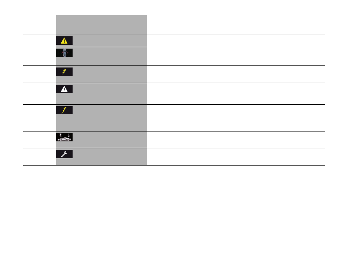
116 Instrument Panel and Multi-Function Display
Wiper defective
Consult a workshop
Have the fault corrected at an authorized Porsche dealer.
Example
Doors/lids open Close door/lid indicated.
System fault
Driving permitted
Consult a workshop
One or more electrical systems may have failed.
Adapt your driving style and speed to the changed conditions.
Have the fault corrected at an authorized Porsche dealer.
Parking Assistant
audio fault
Service
required
Acoustic warning and distance signals for ParkAssist are not available.
Please remember this, e.g. when parking. Have the fault corrected at an authorized Porsche dealer.
Warning light on
the coolant
temperature
gauge flashes
Fault of the
engine control system
Have the fault corrected at an authorized Porsche dealer.
Outside temp. display
defective
Service required
Have the fault corrected at an authorized Porsche dealer.
Example:
Service in xxx km
Service reminder.
Bring the vehicle in for service no later than after the distance/time shown has elapsed.
The intervals in the “Maintenance” booklet are decisive however.
Light in
instrument
panel
Warning and information message in the
multi-function display
Meaning/Action required

Driving and Driving Safety 117
Driving and Driving Safety
Diagnostic Socket.......................................118
Ignition Lock...............................................118
Starting and Stopping the Engine .................119
Electric Parking Brake .................................120
Brakes .......................................................121
Cruise Control.............................................124
Car Audio Operation/Tips ............................126
Porsche Communication Management (PCM).128
USB/iPod
®
and AUX....................................128
Voice Control..............................................129
Porsche Track Precision App .......................129
Lap Trigger ................................................130
Manual Transmission, Clutch........................132
Transmission and Chassis Control Systems ..134
Porsche Stability Management (PSM)............135
ABS Brake System
(Anti-Lock Brake System) .............................138
Porsche Active Suspension Management
(PASM) .......................................................139
Porsche Torque Vectoring (PTV) Functional
Description.................................................140
Dynamic Engine Mounting (PADM) ................140
“Sport” mode..............................................141
Sports Exhaust System ...............................141
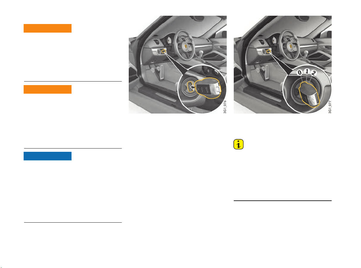
118 Driving and Driving Safety
Diagnostic Socket
External equipment or devices (e.g. navigation
units, head-up displays, etc.) connected to the
diagnostic socket can impair the function of the
vehicle systems.
f Do not connect any equipment or devices to
the diagnostic socket.
Loose equipment/devices or hanging cables in
the driver's footwell can obstruct clearance
around the pedals or become caught between the
pedals when braking or changing direction.
f Do not place any equipment/devices or cables
in the driver's footwell.
The diagnostic socket is for connecting diagnostic
equipment in qualified specialist workshops.
Operating external equipment or devices (e.g.
navigation units, head-up displays, etc.) from the
diagnostic socket when the ignition is switched off
will run down the battery. If the vehicle is parked
for an extended period, the battery can discharge
fully and be damaged (exhaustive discharge).
f Do not connect any equipment or devices to
the diagnostic socket.
Ignition Lock
The ignition key is inserted into the ignition lock to
the right of the light switch at the left of the
steering wheel.
On vehicles with Porsche Entry & Drive, you no
longer have to insert the key into the ignition lock,
but merely keep it with you. The ignition key is
replaced by a control unit in the ignition lock,
which always remains in the ignition lock, unless
the vehicle is being towed.
The ignition lock has three key positions.
Key positions
0 - Initial position
1 - Ignition on
2 - Start engine
Information
The vehicle battery discharges if the ignition key is
left inserted.
If the vehicle battery is dead, the key can only be
removed from the ignition lock if the emergency
operation is performed:
f Please see the chapter “EMERGENCY
OPERATION – UNLOCKING THE IGNITION KEY”
on page 27.
Improper interventions
in the vehicle electrical
system
Loose equipment/
devices or hanging
cables in the driver's
footwell
WARNING
h
WARNING
h
NOTICE

Driving and Driving Safety 119
Ignition lock position 0 – Ignition off
(initial position)
The engine and ignition are off in ignition lock
position 0. The ignition key can be removed in this
position.
Ignition lock position 1 – Ignition on
f Turn ignition key to position 1.
All electrical equipment can be switched on. The
warning lights on the instrument panel light up for
a lamp check.
f Please see the chapter “INSTRUMENT PANEL
USA MODELS” on page 74.
If a load is not switched on for 10 minutes after
switching on the ignition, the ignition must be
switched on again.
Turn the ignition key to ignition lock position 0
(initial position) first.
The ignition key cannot be removed when the
ignition is switched on or when the engine has
been started.
To remove the ignition key:
f Stop the vehicle.
f Switch ignition off.
f Remove the ignition key.
Ignition lock position 2 – Start engine
f Turn ignition key to ignition lock position 2.
The key is reset automatically from position 2 to
position 1 when you start the engine.
Starting and Stopping the Engine
The immobilizer can be deactivated and
the engine started only using an authorized
ignition key.
f Please see the chapter “IMMOBILIZER”
on page 160.
Exhaust gas contains colorless and odorless
carbon monoxide (CO), which is toxic even in low
concentrations. Carbon monoxide can cause
unconsciousness and even death if inhaled.
f Never start or let the engine running in an
enclosed, unventilated area. It is not
recommended to sit in your car for prolonged
periods with the engine on and the car not
moving.
Exhaust fumes and the exhaust system are very
hot when the engine is running. The exhaust
system remains hot for some time after the engine
is turned off.
f Do not park or drive your vehicle where
combustible materials, such as dry grass or
leaves, can come into contact with the hot
exhaust system.
f If your car catches on fire for any reason, call
the fire department. Do not endanger your life
by attempting to put out the fire.
An unattended vehicle with a running engine is
potentialy hazardous. If warning lights come on to
indicate improper operation, no one would be
present to observe the light and turn off the
engine.
f Never leave the engine idling unattended.
Starting the vehicle
f Operate the footbrake.
f Fully depress the clutch pedal and keep it
pressed
f Do not press the accelerator pedal.
The engine control unit will provide the correct
starting mixture.
f Do not operate the starter for more than
approx. 10 seconds. If necessary, repeat the
starting procedure after a pause of approx.
10 seconds. Turn the ignition key back to
ignition lock position 0 (initial position) first.
The first operation of the starter is ended
automatically when the engine starts.
If the engine does not start, subsequent
starter operations will not be ended
automatically.
f Do not warm up the engine when stationary.
Drive off immediately. Avoid high revs and full
throttle until the engine has reached operating
temperature.
f If the vehicle battery power is too weak, the
engine can be started with jump leads.
For information on jump-lead starting:
f Please see the chapter “EXTERNAL POWER
SUPPLY, EMERGENCY STARTING WITH
JUMPER CABLES” on page 207.
Exhaust gas
Exhaust system fire
hazard
WARNING
h
WARNING
h
NOTICE
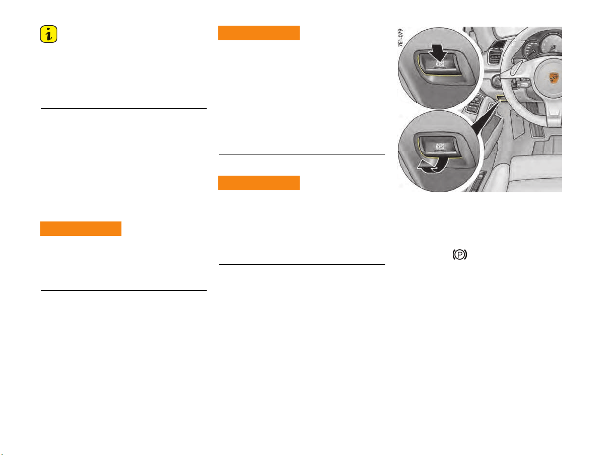
120 Driving and Driving Safety
Information
T
o ensure a good battery charge condition,
thereby ensuring that the battery will start the
engine, all electrical loads that are not required
should be switched off when the ignition is
switched on and when engine revs are low (in
traffic jams, in city traffic or in lines).
Stopping
f Only remove the ignition key when the vehicle
is stationary.
f Only switch the ignition off when the vehicle is
stationary, as there is no power steering and
brake booster assistance when the engine is
switched off.
f When leaving the vehicle, always remove the
ignition key and apply the electric parking
brake.
Engine components become very hot when the
engine is running.
f Before working on any part in the engine
compartment, turn the engine off and let it cool
down sufficiently.
The exhaust pipe is hot when the engine is running
and remains hot for some time after the vehicle is
turned off.
f To prevent injury, make a point of noting where
your vehicle’s exhaust pipe is, avoid placing
your legs near the exhaust pipe when loading
and unloading cargo in the rear, and closely
supervise children around the vehicle during
time when the exhaust pipe could be hot.
A hot exhaust pipe can cause painful skin
burns.
Radiator fan
The fan can start running depending on the
temperature, even with the engine switched off.
f Exercise extreme care that parts of the body,
articles of clothing or jewelry do not get caught
in the radiator fan.
f Exercise extreme caution when working in the
area of the radiator fans.
For information on radiator fans:
f Please see the chapter “RADIATOR FAN,
ENGINE COMPARTMENT BLOWERS”
on page 164.
Electric Parking Brake
The electric parking brake acts on the rear wheels
and serves to secure the vehicle while parked.
Applying the parking brake
f Press switch .
The brake warning light on the instrument
panel lights up.
For information on indicator lights and warning
lights on the instrument panel:
f Please see the chapter “INSTRUMENT PANEL
USA MODELS” on page 74.
Hot engine parts
WARNING
h
Hot exhaust tailpipe
Radiator fan
WARNING
h
WARNING
h
Driving and Driving Safety 121
Releasing the parking brake
The electric parking brake can only be released
when the ignition is switched on.
1. Press the brake pedal.
2. Pull switch .
The brake warning light on the instrument
panel goes out.
Automatic electric parking brake release
when driver’s intention to drive off is
detected
If the engine is running, the driver’s door is closed
and the driver’s safety belt is fastened, it is still
possible to drive off normally even though the
parking brake is on.
The electric parking brake detects the driver’s
intention to drive off and releases automatically.
The warning light on the instrument panel
goes out.
If the driver’s door is not closed or the driver’s
safety belt is not fastened, the electric parking
brake will not be released automatically when the
driver attempts to drive off.
The message “Release parking brake” appears
on the multi-function display in the instrument
panel. The brake warning light on the instrument
panel and the indicator light on the switch
start to flash.
For information on warning messages on the
multi-function display:
f Please see the chapter “OVERVIEW OF
WARNING AND INFORMATION MESSAGES”
on page 109.
Emergency braking function
If the vehicle cannot be stopped by conventional
braking, you can decelerate sharply and stop the
vehicle using the electric parking brake.
f Press switch and keep it pressed.
The brake warning light on the instrument
panel and the indicator light on the switch
start to flash.
The emergency braking function is deactivated
when you release the switch.
Information
Severe braking. Emergency braking takes place
with very high braking power.
f Only use the emergency braking function in an
emergency situation.
f Do not use the emergency braking function to
stop the vehicle when driving normally.
Brake warning light USA
Brake warning light Canada
If the electric parking brake could not be applied
fully when the vehicle is stopped, the brake
warning light on the instrument panel starts to
flash.
For information on warning messages on the multi-
function display:
f Please see the chapter “OVERVIEW OF
WARNING AND INFORMATION MESSAGES”
on page 109.
Brakes
f Make it a habit to check the operation of your
brakes before driving.
Keep in mind that the braking distance increases
very rapidly as the speed increases. At 60 mph
(100 km/h), for example, it is not twice but four
times longer than 30 mph (50 km/h). Tire traction
is also less effective when the roads are wet or
slippery.
f Therefore, always maintain a safe distance
from the car in front of you.
122 Driving and Driving Safety
Vehicles without Porsche Ceramic
Composite Brake (PCCB)
Even though the brake disks consist of alloyed
gray cast iron, they will unavoidably start to
corrode if your car is parked for an extended
period. The brakes will tend to “rub” as a result.
The nature, extent and effects of corrosion
depend on the amount of time the vehicle was
parked, whether road salt or grit was spread and
whether grease-dissolving agents were used in
car washes.
If the braking comfort is noticeably impaired, we
recommend having the brake system checked by
experts at an authorized Porsche dealer.
Brake system function
Your Porsche is equipped with a power assisted
hydraulic dual circuit brake system with disk
brakes at the front and rear.
Both circuits function independently. One brake
circuit operates the front left and rear right wheel
and the other operates the front right and rear left
wheel.
If one brake circuit has failed, the other will still
operate. However, you will notice an increased
pedal travel when you apply the brakes. Failure of
one brake circuit will cause the stopping distance
to increase.
Your vehicle is equipped with an emergency
function in the extreme event of a complete
hydraulic failure of the brake system. If your brake
pedal goes all the way to the floor, do not pump
the brakes.
f Push the brake pedal down firmly and hold it in
that position. A mechanical linkage activates
the second circuit, and you will be able to bring
the vehicle to a stop.
f After bringing your vehicle to a complete stop,
avoid driving the vehicle and instead have it
towed to the nearest authorized Porsche
dealer for repair.
Brake system warning light
You can check the functionality of the brake
system warning light by switching the ignition to
the “On” position (position 1) and verifying that the
warning light illuminates.
Brake warning light USA
Brake warning light Canada
The warning light in the instrument panel lights up.
A message will be displayed on the multi-function
display of the instrument panel if the brake fluid
level is too low, or (if the brake pedal travel has
increased) one of the two brake circuits has failed.
A greater braking pressure will be required,
stopping distances will be longer and the braking
behavior will change, particularly in curves.
With correctly adjusted brakes and a correctly
working brake system, the pedal travel to the
point of brake application should be 1-3/16 in. to
1-9/16 in. (30 to 40 mm). Whenever the brake
pedal travel exceeds this value, have the brake
system checked.
Brake pedal
Unsuitable or incorrectly fixed floor mats or
objects can reduce the travel of the brake pedal or
prevent from applying the brake pedal.
f Always check the movement of the brake
pedal before driving and make sure that it is
not obstructed by a floor mat or any other
object.
f Secure the floor mat to prevent it from sliding
into positions that could interfere with the safe
operation of your vehicle.
Your authorized Porsche dealer will be glad to
offer you floor mats of the correct size
including a securing possibility.
Information
In case one of the two brake circuits fails,
increased pedal travel is required to bring your
vehicle to a full stop.
Brake hydraulic failure
r
ecovery
WARNING
h
Obstruction of brake
pedal
WARNING
h

Driving and Driving Safety 123
f Before descending a steep grade, reduce
speed and shift the transmission into a lower
gear to control speed.
f Do not “ride the brakes” by resting your foot on
the pedal when not intending to apply brake
pressure.
f Do not hold the pedal down too long or too
often. This could cause the brakes to overheat
and lose braking power.
Brake booster
The brake booster assists braking only when
the engine is running.
When the car is moving while the engine is not
running, or if the brake booster is defective, more
pressure on the brake pedal is required to bring
the car to a stop.
Moisture, road salt or grit on brakes affects
braking.
Brakes will dry after a few cautious brake
applications.
Driving through water may reduce the traction.
Moisture on brakes from road water, car wash, or
a coating of road salt or grit may affect braking
efficiency.
f Cautiously apply brakes to test and dry the
brakes after exposure to road water, etc.
The brake booster is ready for operation only
while the engine is running.
If the engine is switched off or there is a defect in
the brake booster, much greater force has to be
applied to the pedal when braking.
f Vehicles with defective brakes must not
be towed and must be transported on a flat
bed.
For information on towing:
f Please see the chapter “TOWING”
on page 214.
Brake wear
Your car has excellent brakes, but they are still
subject to wear. The rate at which they wear
depends on how the brakes are used.
f Have the brake system inspected at the
intervals recommended in your Maintenance
Booklet.
Brake system warning light
You can check the functionality of the brake
system warning light by switching the ignition to
the “On” position (position 1) and verifying that the
warning light illuminates.
A warning message will be displayed on the multi-
function display of the instrument panel if the
brake pads are worn, excessively.
f Adapt your driving style and speed to the
changed conditions.
f Have your authorized Porsche dealer inspect
or replace the brake pads.
For information on warning messages on the
multi-purpose display:
f Please see the chapter “OVERVIEW OF
WARNING AND INFORMATION MESSAGES”
on page 109.
Brake pads and brake disks
Wear on the brake pads and brake disks depends
to a great extent on the driving style and the
conditions of use and therefore cannot be
expressed in actual miles on the road.
The high-performance brake system is designed
for optimal braking effect at all speeds and
temperatures.
Certain speeds, braking forces and ambient
conditions (e.g. temperature and humidity) can
therefore cause the brakes to “squeal”.
Unsuitable or incorrectly installed floor mats or
objects can obstruct the movement of the brake
pedal or prevent application of the brake pedal.
f Do not obstruct the pedal travel with floor mats
or other objects.
Riding the brakes
Wet brakes
WARNING
h
WARNING
h
Loss of braking power
WARNING
h
Brake wear warning message USA
Brake wear warning message
Canada
Obstructed brake pedal
WARNING
h
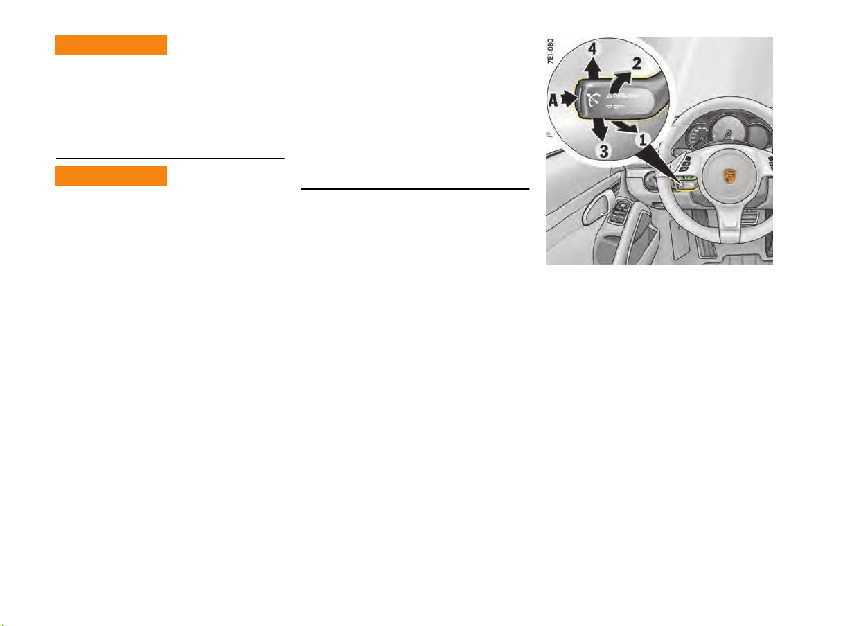
124 Driving and Driving Safety
In heavy rain, while driving through water or after
leaving a car wash, the braking action may be
delayed and incr
eased pressure may be required.
f For this reason, keep further back from the
vehicle in front and “dry” the brakes by
applying them at intervals. Make sure that the
traffic behind you is not affected.
After a long drive over salted or gritted roads,
a coating may form on the brake disks and pads
that significantly reduces friction and therefore
also braking effect.
f Even though the brake disks consist of alloyed
gray cast iron, they will unavoidably start to
corrode if your vehicle is parked for an
extended period. The brakes will tend to “rub”
as a result.
The nature, extent and effects of corrosion
depend on the amount of time the vehicle was
parked, whether road salt or grit was spread
and whether grease-dissolving agents were
used in car washes (not on vehicles with
Porsche Ceramic Composite Brake).
To prevent corrosion of the brake disks,
“brake them dry” before parking the vehicle
(not on vehicles with Porsche Ceramic
Composite Brake).
If braking comfort is noticeably impaired, we
recommend that you have the brake system
checked by experts at an authorized Porsche
dealer.
f To relieve the brake system on downhill
stretches, change down to a lower gear in
good time (engine braking).
If engine braking is insufficient on steep
stretches, operate the footbrake at intervals.
Avoid continuous braking as it overheats the
brakes and reduces the braking effect.
For information on brake fluid and checking the
brake fluid level:
f Please see the chapter “BRAKE FLUID”
on page 185.
New brake pads or linings
New brake pads have to be “broken in”, and
therefore only attain optimal friction when the car
has covered several hundred miles or km.
The slightly reduced braking ability must be
compensated for by pressing the brake pedal
harder. This applies whenever the brake pads
and/or brake disks are replaced.
A - Switch cruise control on/off
1 - Set/increase desired speed
2 - Reduce desired speed
3 - Interrupt (OFF)
4 - Return to set speed (RESUME)
Cruise Control
Cruise control maintains any selected speed
between approx. 20–150 mph (30–240 km/h)
without you having to use the accelerator.
Cruise control is operated using the control stalk
at the bottom left of the steering wheel.
Wet brakes
Reduced braking
ef
ficiency
WARNING
h
WARNING
h

Driving and Driving Safety 125
If the current traffic situation does not allow you to
drive safely at a constant speed and with sufficient
distance to the vehicle in front, using the cruise
control can cause accidents.
f Do not use the cruise control in heavy traffic,
in city traffic, on twisting roads or under
unfavorable road conditions (e.g. wintry or wet
conditions, varying road surfaces).
f Observe all local and national speed limits.
f Do not reach through the steering-wheel
spokes while driving.
Switching cruise control readiness on
f Press button A on the control stalk.
Maintaining and storing speed
1. Accelerate or decelerate to the desired speed
using the accelerator pedal.
2. Push the control stalk on the steering wheel
forward (position 1).
The current driving speed is now stored as the
desired speed, which will be maintained
automatically.
Accelerating (e.g. to overtake)
Variant 1
f Increase the speed as usual with the
accelerator pedal.
When you ease off the accelerator, the
previously stored value is set again.
Variant 2
f Push the control stalk on the steering wheel
forward (position 1).
The desired speed is increased in steps of
1 mph (1 km/h).
or
Press the control stalk on the steering wheel
forward and keep it pressed (position 1).
The desired speed is increased in steps of
5 mph (10 km/h).
The new desired speed is displayed on the multi-
function display in the instrument panel.
Decelerating
f Briefly pull the control stalk on the steering
wheel towards the steering wheel (position 2).
The desired speed is decreased in steps of
1 mph (1 km/h).
or
Pull the control stalk on the steering wheel
towards the steering wheel and keep it pulled
(position 2).
The desired speed is decreased in steps of
5 mph (10 km/h).
The new desired speed is displayed on the multi-
function display in the instrument panel.
Interrupting cruise control
operation – OFF
The speed driven before the interruption remains
stored in the memory and can be reactivated by
pressing the control stalk.
f Please see the chapter “RESUMING THE
STORED SPEED – RESUME” on page 126.
f Press the control stalk down (position 3).
Cruise control operation is interrupted
automatically:
– If the set vehicle speed is exceeded by more
than approx. 16 mph (25 km/h) for longer
than 20 seconds.
– If the actual vehicle speed falls below the set
vehicle speed by approx. 37 mph (60 km/h)
for longer than 60 seconds (e.g. gradients).
– If Porsche Stability Management (PSM)
intervenes for longer than 0.5 seconds.
Misuse of cruise control
Cruise control readiness
The grey symbol on the multi-function
display in the instrument panel indicates
readiness.
Desired speed
The desired speed that was stored is
displayed under the cruise control
symbol, which has now turned orange.
WARNING
h
126 Driving and Driving Safety
Resuming the stored speed – RESUME
f Press the control stalk up (position 4).
Cruise control accelerates/decelerates the
vehicle to the stored speed.
Information
The stored speed should only be recalled if traffic
and road conditions are conducive to driving at
that speed.
Switching cruise control readiness off
f Press button A on the control stalk.
The memory is cleared and the readiness
symbol disappears.
The stored desired speed is cleared when the
ignition is switched off when the vehicle is parked.
Information
On upward or downward slopes, the set speed
cannot always be maintained by cruise control
(vehicles with manual transmission).
f To obtain sufficient engine braking or a better
rev range, you therefore have to change down
to a lower gear.
Car Audio Operation/Tips
For radio operation see your radio manual
which is included with your on-board
literature.
FM reception
A vehicle is not an ideal place to listen to a radio.
Because the vehicle moves, reception conditions
are constantly changing.
Buildings, terrain, signal distance and noise from
other vehicles are all working against good
reception.
Some conditions affecting FM may appear to be
problems when they are not.
The following characteristics are completely
normal for a given reception area, and they do not
indicate any problem with the radio itself.
Information
Electronic accessories should only be installed by
your authorized Porsche dealer.
Equipment which has not been tested and
approved by Porsche may impair radio reception.
Fading and drifting
FM range is limited to about 25 miles (40 km),
except for some high power stations.
If a vehicle is moving away from the desired
station's transmitter, the signal will tend to fade
and/or drift. This condition is more prevalent with
FM than AM, and is often accompanied by
distortion.
Fading and drifting can be minimized to a certain
degree by careful attention to fine tuning or
selection of a stronger signal.
Static and fluttering
When the line-of-sight link between a transmitter
and vehicle is blocked by large buildings or
mountains, the radio sound may be accompanied
with static or fluttering because of the
characteristic of FM.
In a similar effect, a fluttering noise is sometimes
heard when driving along a tree-lined road.
This static and fluttering can be reduced by
adjusting the tone control for greater bass
response until the disturbance has passed.
Multipath
Because of the reflecting characteristics of FM,
direct and reflected signals may reach the antenna
at the same time (multipath) and cancel each other
out. As a vehicle moves through these electronic
dead spots, the listener may hear a momentary
flutter or loss of reception.
Station swapping
When two FM stations are close to each other, and
an electronic dead spot, such as static or
multipath area, interrupts the original signal,
sometimes the stronger second signal will be
selected automatically until the original one
returns. This swapping can also occur as you
drive away from the selected station and
approach another station of a stronger signal.

Driving and Driving Safety 127
Compact disk player
To avoid damage to compact disk player and
disks.
f Use only compact disks labeled as shown,
having no dirt, damage or warpage.
f Never attempt to disassemble or oil any part
of the player unit. Do not insert any object
other than a disk into the slot. Remember there
are no user-serviceable parts inside the
compact disk player.
f Do not allow the disk to sustain any
fingerprints, scrapes or stickers on the
surfaces. This may cause poor sound quality.
Hold the disk only on the edge or center hole.
f When not in use, take the disk out of the player,
put the disk back into its case and store it
away from dust, heat, damp and direct
sunlight.
Leaving the disk on the dashboard in the sun
can damage the disk.
f If the disk gets dirty, clean the disk by wiping
the surfaces from the center to the outside in
a radial direction with a soft cloth.
Do not use a conventional record cleaner or
anti-static record preservative.
Disk cleaners are available in audio stores.
Car Telephone and Aftermarket Alarms
Important legal and safety information
regarding the use of cellular telephones
Some jurisdictions may prohibit the use of cellular
telephones while driving a vehicle. Check the laws
and regulations on the use of cellular telephones
in the areas where you drive.
Looking away from the road or turning your
attention away from your driving to operate a cell
phone will sooner or later cause an accident.
f Do not attempt to operate a hand-held cell
phone while you are driving. Safety is more
important than a phone call.
f Learn to operate the hands-free phone, if it is
available, before you start driving. Then make
use of the hands-free phone at all times.
It is essential to observe the telephone
manufacturer’s instructions before operating
the telephone.
Any portable telephone or radio transmitter which
is used in a Porsche must be properly installed in
accordance with the technical requirements of
Porsche.
The transmission power must not exceed
10 W.
The devices must possess a type approval for
your vehicle and have an “e” symbol.
If you should require equipment with transmission
power values greater than 10 W, please consult
your authorized Porsche dealer for this purpose.
They are familiar with the technical requirements
for installing devices of this kind.
The antennas for all radios and telephones with a
transmitting antenna must be externally mounted.
The improper installation of radios or telephones
or use of a radio or telephone with a transmitting
antenna inside the car may cause the warning
lights to come on.
Improper installation of such equipment can
create a discharged battery or excessive current
draw from added equipment.
If aftermarket systems are installed by non-
dealership technicians or outside the selling
dealer, problems may result. Installation of
aftermarket equipment is not covered under the
New Car Warranty.
f Consult your authorized Porsche dealer about
the installation of non-Porsche approved
equipment.
Reception quality
The reception quality of your car telephone will
change constantly when you are driving.
Interference caused by buildings, landscape and
weather is unavoidable. It may become particu-
larly difficult to hear when using the hands-free
function due to external noise such as engine and
wind noise.
Automatic car-wash
f Unscrew external antennas before using an
automatic car-wash.
NOTICE
Cell phone use
DANGER
h
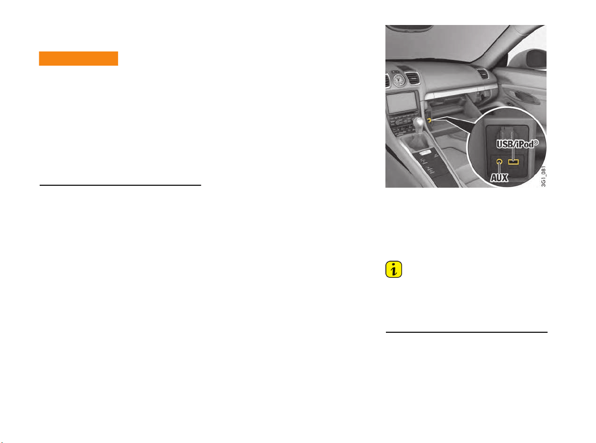
128 Driving and Driving Safety
Porsche Communication
Management (PCM)
Setting or operating the multi-function display,
radio, navigation system, telephone or other
equipment when driving could distract you from
the traffic. You could lose control of the vehicle.
f Operate the components while driving only if
the traffic situation allows you to do so safely.
f Carry out any complicated operating or setting
procedures only with the vehicle stationary.
f If it is necessary to operate these components
while the vehicle is in motion, use the function
keys on the multi-functional steering wheel.
f Refer to the separate operating instructions
before putting the PCM into operation.
When put into operation for the first time, a
distance of approx. 3 miles (5 km) must be driven
in order for the navigation system to complete the
process of fine calibration. The same applies
when the tires are changed (e.g. summer/snow
tires) or new tires fitted. Full location accuracy is
not yet achieved during the fine-calibration
process.
If the vehicle has been transported (e.g. ferry, car
train), the system may take a few minutes after
being switched on before it determines the current
location.
Serious tire slip (e.g. spinning wheels on snow)
may result in temporarily inaccurate navigation.
When the battery has been disconnected, it may
take up to 15 minutes before the navigation
system is operational once more.
Satellite radio
You must have the satellite radio activated before
you can put it into operation. You will need a
contract with a provider in order to use this radio.
f Refer to the separate radio operating
instructions before putting into operation.
USB/iPod
®
and AUX
The USB/iPod
®
and AUX interfaces are located in
the glove box.
f Please refer to the chapter “EXTERNAL AUDIO
SOURCE” in the separate PCM operating
instructions.
Information
Do not leave your iPod
®
, USB storage device or
an external audio source in the vehicle for
extended periods of time because extreme
ambient conditions (temperature fluctuations,
humidity) can occur in the vehicle.
Operation of on-board
systems
WARNING
h
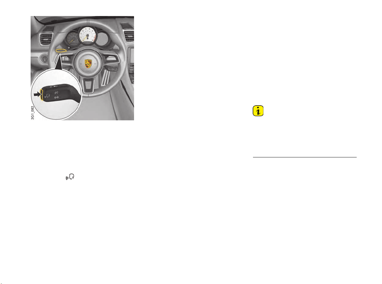
Driving and Driving Safety 129
Voice Control
Porsche Communication Management (PCM) can
be operated by spoken commands using the voice
control system.
f Please refer to the chapter “VOICE CONTROL”
in the separate PCM operating instructions.
Activating voice control
f Press button .
An acoustic signal sounds and help text for
using the five most important voice commands
appears on the multi-function display in the
instrument panel.
Simply say the command.
For information on switching the help text on and
off on the multi-function display:
f Please see the chapter “DISPLAYING PCM
INFORMATION ON THE MULTI-FUNCTION
DISPLAY” on page 101.
Porsche Track Precision App
USA: QZ9-APPGATEWAY
Canada: 5927A-APPGATEWAY
This device complies with Part 15 of the FCC
Rules (and with Industry Canada licence-exempt
RSS standard(s)).
Operation is subject to the following two
conditions:
1. This device may not cause harmful
interference, and
2. this device must accept any interference
received, including interference that may
cause undesired operation.
Changes or modifications made to this equipment
not expressly approved by Porsche may void the
FCC authorization to operate this equipment.
This equipment has been tested and found to
comply with the limits for a Class B digital device,
pursuant to Part 15 of the FCC Rules.
These limits are designed to provide reasonable
protection against harmful interference in
a residential installation.
This equipment generates, uses and can radiate
radio frequency energy and, if not installed and
used in accordance with the instructions, may
cause harmful interference to radio
communications. However, there is no guarantee
that interference will not occur in a particular
installation.
If this equipment does cause harmful interference
to radio or television reception, which can be
determined by turning the equipment off and on,
the user is encouraged to try to correct the
interference by one or more of the following
measures:
– Reorient or relocate the receiving antenna.
– Increase the separation between the
equipment and receiver.
– Connect the equipment into an outlet on a
circuit different from that to which the receiver
is connected.
– Consult the dealer or an experienced radio/TV
technician for help.
Information
Radiofrequency radiation exposure: The
radiated output power of the device is far below
the FCC radio frequency exposure limits.
Nevertheless, the device shall be used in such a
manner that the potential for human contact
during normal operation is minimized.
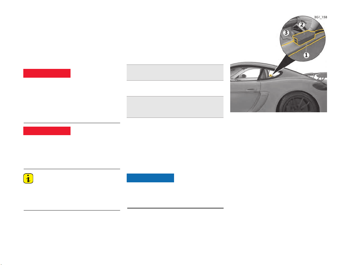
130 Driving and Driving Safety
The Porsche Track Precision app can be used to
connect to the vehicle via a wir
eless local network
(WLAN). This enables driving data to be displayed,
recorded and analysed directly on a smartphone.
Detailed information on installation and the
functions of the Porsche Track Precision app is
available directly in the app and at
www.porsche.com or from your authorized
Porsche dealer.
Driving at excessive speeds and risky maneuvers
may lead to loss of control over the vehicle.
f Adapt your driving style and maneuvers to your
personal ability, the road and weather
conditions, as well as the traffic situation.
f Only use the Porsche Track Precision app on
closed circuits away from public roads.
Use of the app while driving can distract your
attention from the road. You may lose control of
the vehicle.
f Carry out operating and setting procedures
only whilst the vehicle is stationary.
Information
Since vehicle-specific data can be accessed
using the Porsche Track Precision app, it is
recommended to protect this data from
unauthorized access by third parties.
Lap Trigger
The lap trigger enables lap times to be
automatically measured. The system consists of
an infrared transmitter positioned at the edge of
the circuit and an infrared receiver mounted in the
vehicle.
Technical data
Notes on the receiver
– The receiver can be installed on the left or right
in the vehicle depending on the race circuit.
– To guarantee optimum reception, there must
be a direct line of sight between the receiver
and transmitter.
– Direct sunlight hitting the receiver will interfere
with reception.
Ambient temperatures of below 50 °F (10 °C) can
cause permanent damage to the receiver.
f Remove the receiver from the vehicle if the
ambient temperature is below 50 °F (10 °C).
Installing the receiver
f Mount the receiver 2 horizontally on the
bracket 1. The receiver eye 3 should be
pointing out of the rear side window.
Loss of control over the
vehicle
Setting and operating
when driving
DANGER
h
DANGER
h
Permissible voltage range
of the transmitter
11 V to 16 V
Power consumption of
the transmitter
1.2 W
Permissible temperature
range of the receiver
50 °F (10 °C)
to
140 °F (60 °C)
NOTICE
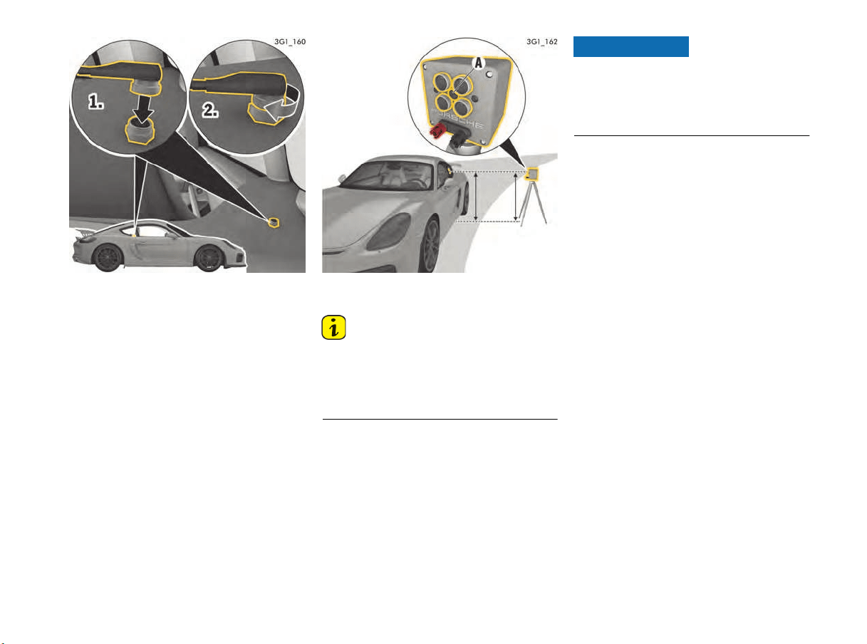
Driving and Driving Safety 131
Connecting the receiver
1. Insert the receiver cable into the socket behind
the passenger seat.
2. Screw the connector onto the socket.
Installing the transmitter at the edge of
the circuit
Information
If multiple vehicles with the Porsche lap trigger
system will be driving on a race circuit, only one
transmitter should be installed. The receiver
cannot differentiate the transmitters and detects
each passing of a transmitter as a new lap.
A commercially available camera tripod, for
example, can be used for adjusting the transmitter
height.
Alternatively the transmitter can be placed on a
flat, firm surface.
Risk of damage to the transmitter
The airflow from passing vehicles can cause the
transmitter to fall down or over.
f Choose the transmitter location so that a safe,
firm position is guaranteed.
1. Position transmitter A at the edge of the circuit
at the start line at the same level as the
receiver in the vehicle.
2. Align transmitter A parallel to the track.
NOTICE
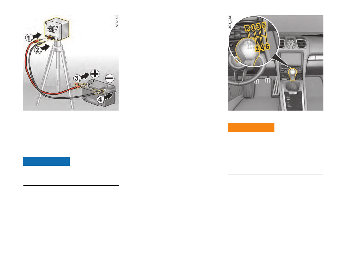
132 Driving and Driving Safety
Connecting the power supply for the
transmitter
A commercially available motorcycle or car
battery, for example, can be used for the power
supply to the transmitter.
f Make sure that the battery is sufficiently
charged.
Risk of damage due to short circuit.
f Keep the battery dry.
f Make sure the polarity is correct.
1. Insert the red cable into the red connection on
the transmitter.
2. Insert the black cable into the black connection
on the transmitter.
3. Connect the red cable to the positive terminal
(+) of the battery.
4. Connect the black cable to the negative
terminal (-) of the battery.
Starting timing
The first lap must be manually started in the
“Chrono” menu on the multi-function display.
The lap times are then recorded automatically.
For instructions on starting the timing:
f Please see the chapter “STARTING TIMING”
on page 93.
Manual Transmission, Clutch
Unsuitable or improperly secured floor mats or
objects can restrict pedal travel or hinder pedal
operation.
f Do not obstruct the pedal travel with floor mats
or other objects.
Nonskid floor mats of the correct size are
available at your authorized Porsche dealer.
The positions of the gears are shown on the shift
pattern on the gearshift lever.
f When changing gears, always ensure that the
clutch pedal is fully depressed and the gear
has engaged fully.
f Select reverse gear only when the vehicle is
stationary.
Reverse gear can be engaged after moving the
gearshift lever to the left past the stop.
NOTICE
Blocked pedals
WARNING
h
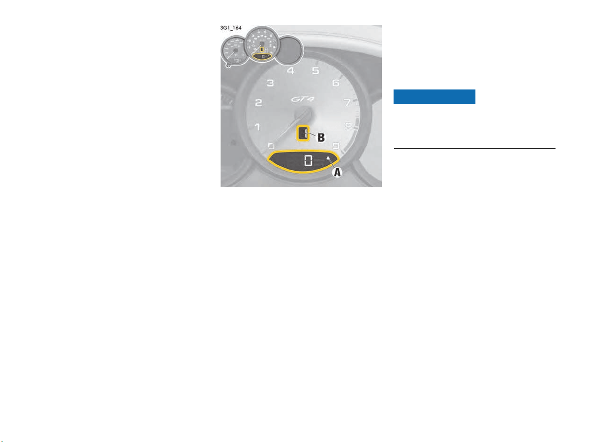
Driving and Driving Safety 133
f Select an appropriately low gear on upward
and downward slopes.
This will ensure optimum use of engine power
and engine braking.
When reverse gear is selected and the ignition is
on, the reversing lights come on.
Upshift prompt for fuel-economy-
optimised driving
The consumption-oriented upshift indicator A in
the tachometer at the right beside the digital
speed display helps you to develop a fuel-saving
driving style.
The upshift indicator lights up – prompting you to
shift up to the next-higher gear – depending on the
selected gear, engine speed and accelerator
pedal position.
f Change to the next-higher gear when the
upshift indicator lights up.
Gear display
The gear display B in the tachometer indicates the
currently engaged gear.
Permitted engine speed
f You should change into a higher gear or ease
off the accelerator before the needle reaches
the red mark on the tachometer.
If the red zone is reached during acceleration,
fuel feed is interrupted.
Risk of engine damage (overrevving) when shifting
down to a lower gear.
f Take care not to exceed the maximum
permitted engine speed when shifting down.
NOTICE

134 Driving and Driving Safety
Transmission and Chassis Control Systems
Your Porsche sports car features a complex integrated system made up of all control systems acting in power transmission and in the chassis.
All control systems are networked with the aim of combining the best possible driving performance with maximum safety.
The following systems are involved:
System/designation Scope
PSM
Porsche Stability Management
– Driving stability control
– Anti-lock brake system (ABS)
– Brake booster (Hydraulic Brake Assist)
– Automatic brake differential (ABD)
– Anti-slip control (ASR)
– Engine drag torque control (MSR)
– Drive-Off Assistant
PASM
Porsche Active Suspension Management
– Shock absorber system with adaptive, continuous shock absorber control
PTV
Porsche Torque Vectoring
– Laterally dynamic braking intervention for more agile cornering
– Rear differential lock with fixed asymmetrical locking ratio

Driving and Driving Safety 135
Despite the advantages of transmission and
chassis control systems, it is still the driver’s
responsibility to adapt his driving style and
maneuvers in line with road and weather
conditions, as well as the traffic situation.
The increased safety that is provided should not
induce you to take greater risks with your safety.
The limits set by the physics of driving cannot be
overcome.
These systems cannot reduce the risk of
accidents due to inappropriate speed.
f Adapt your driving style, maneuvers and speed
to the road and weather conditions, as well as
the traffic situation.
Porsche Stability Management
(PSM)
PSM is an active control system for stabilization of
the vehicle during extreme driving maneuvers.
PSM makes use of both the automatic brake
differential (ABD) and anti-slip regulation (ASR)
systems, as well as the functions of the anti-lock
brake system (ABS) and engine drag torque
control system (MSR).
In spite of the advantages of PSM, it is still the
driver’s responsibility to adapt his driving style and
maneuvers in line with road and weather
conditions, as well as the traffic situation.
The increased safety that is provided should not
induce you to take greater risks with your safety.
The limits set by the physics of driving cannot be
overcome, even with PSM.
Risk of accidents due to inappropriate speed
cannot be reduced by PSM.
Advantages of PSM
– Best possible traction and lane-holding ability –
even on road surfaces with varying friction.
– The system compensates for undesired
vehicle reactions (Ferraria effect) when the
driver releases the accelerator pedal or brakes
on bends. This compensation functions up to
the maximum lateral acceleration.
– PSM actively stabilizes the vehicle if necessary
during dynamic driving maneuvers (e.g. rapid
steering movements, during lane changes,
or on alternating bends).
– Improved braking stability on bends and on
different or varying road surfaces.
– Improved brake function and shorter stopping
distance in the event of emergency braking.
Readiness for operation
PSM is switched on automatically every time you
start the engine.
Function
Sensors at the wheels, brakes, steering system
and engine continuously measure:
– Speed
– Direction of travel (steering angle)
– Lateral acceleration
– Axial acceleration
– Rate of turn about the vertical axis
PSM uses these values to determine the direction
of travel desired by the driver.
PSM intervenes and helps to correct the course if
the actual direction of motion deviates from the
desired course (steering-wheel position):
It brakes individual wheels as required.
If necessary, PSM also influences the engine
power.
The events below inform the driver of PSM control
operations and warn him to adapt his driving style
to the road conditions:
– PSM warning light on the instrument panel
flashes.
– Hydraulic noises can be heard.
– The vehicle decelerates and steering-wheel
forces are altered as PSM controls the brakes.
– Reduced engine power.
– The brake pedal pulsates and its position is
changed during braking.
In order to achieve full vehicle deceleration,
foot pressure must be increased after the
brake pedal has begun vibrating.
Driver responsibility
WARNING
h
Loss of control over the
vehicle
WARNING
h

136 Driving and Driving Safety
Examples of PSM control operations
–
If the “front wheels of the vehicle drift” on a
bend, the engine power is reduced and the
rear wheel on the inside of the bend is braked
if necessary.
– If the rear of the vehicle swings out on a bend,
the front wheel on the outside of the bend is
braked.
– Brake booster (Hydraulic Brake Assist):
In the event of an emergency braking operation
where the pedal force is insufficient, a brake
booster provides the braking pressure
necessary for maximum deceleration at all
4 wheels.
Automatic brake differential (ABD)
The ABD system controls the front and rear axles
separately. If one wheel of an axle starts to spin,
it is braked so that the other wheel on the same
axle can be driven.
ABD recognizes different driving states, and it
features control strategies adapted to these
states. In situations in which little propulsive power
is required, such as when the vehicle moves off on
a level gravel surface, traction control already
becomes active at low engine speeds. If a large
amount of propulsive power is required, e.g. when
driving off on an uphill slope or for rapid
acceleration, the ABD system is adapted
accordingly.
Anti-slip control (ASR)
The anti-slip control system prevents the wheels
from spinning by adjusting the engine power,
thereby ensuring good lane-holding ability and
stable handling.
Engine drag torque control (MSR)
In conditions of excessive slip, the engine drag
torque control system prevents all driven wheels
from locking up when the vehicle is overrunning.
This is also the case for downshifts on a slippery
road.
Switching off PSM
PSM can be switched off in 2 stages:
– Stage 1 ESC OFF:
Switch off Electronic Stability Control (ESC).
– Stage 2 ESC+TC OFF:
Also switch off Traction Control (TC).
There is no stabilizing brake control in either of the
switch-off stages (even when the brakes are
used).
f PSM should always be switched on during
“normal” driving. This particularly applies in
wet conditions.
However, it may be a good idea to switch off PSM
temporarily in exceptional situations:
– On a loose surface and in deep snow.
– When “rocking the vehicle free”.
No Brake Control in
Switch-Of
f Stages
WARNING
h
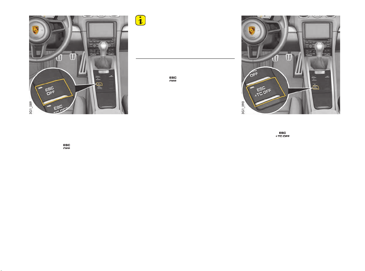
Driving and Driving Safety 137
Switching off Electronic Stability Control
(ESC)
Condition: Indicator light on the ESC+TC OFF
button is off.
f Press button .
Electronic Stability Control (ESC) is
switched off after a short delay.
When the system is switched off, the indicator
light on the button and the PSM OFF warning
light on the speedometer light up.
The message “ESC switched off” appears on
the multi-function display in the instrument
panel for approx. 4 seconds.
An acoustic signal also sounds.
Information
– When Electronic Stability Control (ESC) is
switched off, sportier Traction Control is
activated.
– Brake interventions are deactivated.
– The ABS remains active.
Switch Electronic Stability Control (ESC)
back on
f Press button .
Electronic Stability Control (ESC) is active
immediately.
The indicator light on the button and the PSM
OFF warning light on the tachometer go out.
The message “ESC switched on” appears on
the multi-function display in the instrument
panel for approx. 4 seconds.
Switching off Electronic Stability Control
(ESC) and Traction Control (TC)
f Press button .
Electronic Stability Control (ESC) and Traction
Control (TC) switch off completely after a short
delay.
When the system is switched off, the indicator
light on the button and the PSM OFF warning
light on the tachometer and TC OFF warning
light on the speedometer light up.
The message “ESC + TC switched off”
appears on the multi-function display in the
instrument panel for approx. 4 seconds.
A gong signal also sounds.

138 Driving and Driving Safety
Information
–
All PSM functions are deactivated.
– ABS remains active.
– If PSM is deactivated directly using the
ESC+TC OFF button, the indicator light on the
ESC button also lights up.
Switching Electronic Stability Control (ESC)
and Traction Control (TC) back on
f Press button .
PSM is active immediately.
The indicator light on the button, the PSM OFF
warning light on the tachometer and the TC
OFF warning light on the speedometer go out.
The message “ESC + TC switched on”
appears on the multi-function display in the
instrument panel for approx. 4 seconds.
Information
When PSM is switched off, Traction Control (TC)
can be switched on separately:
f Press button .
Traction Control (TC) is active immediately.
The indicator light on the button and
the TC OFF warning light on the speedometer
go out.
Electronic Stability Control (ESC) remains
switched off.
PSM warning light
– The PSM warning light on the instrument panel
lights up for a lamp check when the ignition is
switched on.
– The light indicates PSM control operations,
e.g. brake control in the event of one-sided
wheel spin.
– The light – in conjunction with the multi-function
display – indicates a fault.
The warning message “ESC + TC failure
Adapted driving permitted” appears on the
multi-function display in the instrument panel.
For information on warning messages on the multi-
function display:
f Please see the chapter “OVERVIEW OF
WARNING AND INFORMATION MESSAGES”
on page 106.
f Adapt your driving style and speed to the
changed conditions.
f Contact a qualified specialist workshop in
order to correct the fault. We recommend that
you get an authorized Porsche dealer to do
this work as they have trained workshop
personnel and the necessary parts and tools.
Towing
For information on towing:
Please see the chapter “TOWING”
on page 230.Additional steering forces also
assist the driver during countersteering.
ABS Brake System
(Anti-Lock Brake System)
In spite of the advantages of ABS, it is still the
driver’s responsibility to adapt his driving style
and maneuvers in line with road and weather
conditions, as well as the traffic situation.
The increased safety that is provided should not
induce you to take greater risks with your safety.
The limits set by the physics of driving cannot be
overcome, even with ABS.
Risk of accidents due to inappropriate speed
cannot be reduced by ABS.
ABS ensures
– Full steering control
Vehicle remains steerable
– Good driving stability
No skidding due to locked wheels
– Optimum braking distance
Shorter stopping distance in most cases
– Prevention of wheel locking
No flat spots on the tires
Loss of control over
the vehicle
WARNING
h
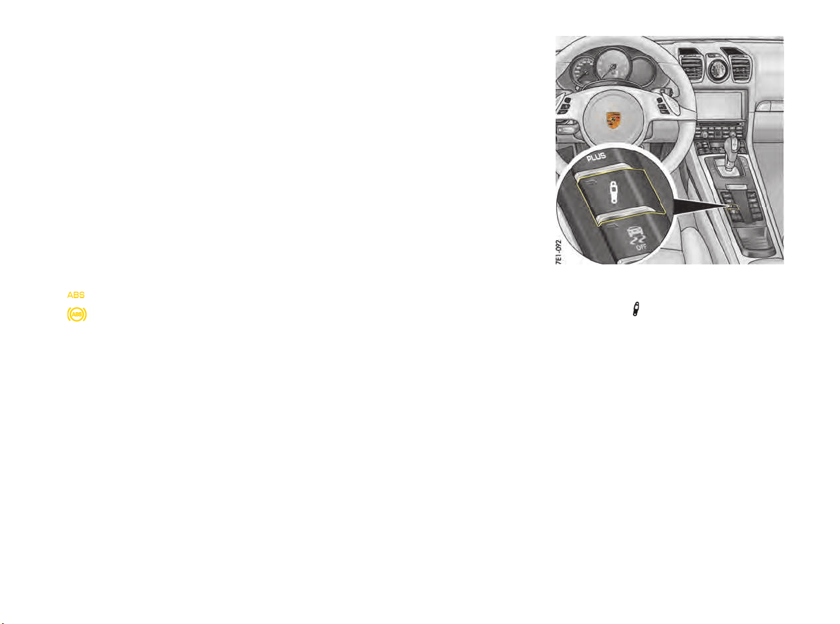
Driving and Driving Safety 139
Function
The decisive advantage of ABS lies in the driving
stability and manoeuvrability of the vehicle in
hazardous situations.
ABS prevents locking of the wheels during full
braking, on almost all road surfaces, until just
before the vehicle stops.
ABS begins to control the braking process as
soon as a wheel shows a tendency to lock.
This controlled braking process is comparable
with extremely rapid cadence braking.
The pulsating brake pedal and a “juddering noise”
warn the driver to adapt his driving speed to the
road conditions.
f If full braking is necessary, press the brake
pedal fully during the whole braking operation,
even though the pedal is pulsating. Do not
reduce brake pressure.
Warning light USA
Warning light Canada
If the ABS warning light lights up on the instrument
panel while the engine is running, the ABS has
switched off because of a fault.
The warning message “ABS/PSM failure
Adapted driving permitted” appears on the
multi-function display in the instrument panel.
For information on warning messages on the multi-
function display:
f Please see the chapter “OVERVIEW OF
WARNING AND INFORMATION MESSAGES”
on page 109.
In this case, the braking system will operate
without lock prevention, as in vehicles without
ABS.
f Adapt your driving style to the changed
braking behavior.
The ABS must be checked by your Porsche
dealer in order to prevent the occurrence of
further faults with unpredictable
consequences.
Please contact a qualified specialist workshop.
We recommend that you get an authorized
Porsche dealer to do this work as they have
trained workshop personnel and the necessary
parts and tools.
The ABS control unit is adjusted for the approved
tire dimensions.
The use of tires with non-approved dimensions can
lead to different wheel speeds, causing ABS to
switch off.
Porsche Active Suspension
Management (PASM)
The PASM system actively adjusts the shock
absorbers. The adjustable damper system selects
the appropriate damping level for each wheel
according to the driving situation and driving
conditions. Driving safety, agility and comfort are
optimised.
Two different chassis setups can be selected at
the push of a button:
– “Chassis Normal”
– “Chassis Sport”
In Normal mode, the chassis is in a basic setup for
public roads and race circuits with uneven
surfaces.
Sport mode provides a shock absorber tuning for
particularly high driving dynamics (e.g. on even
race circuits).
In addition to manual mode selection, PASM also
adjusts shock absorber tuning for either sporty or
comfort driving, depending on the driving
situation.
Selecting the PASM mode
1. Switch on ignition.
2. Press button (repeatedly).
On the button:
– No indicator light comes on when “Chassis
Normal” is selected (default setting).
– An indicator light comes on when “Chassis
Sport” is selected.
In addition, the selected chassis setup is shown on
the multi-function display in the instrument panel
for approx. 4 seconds.

140 Driving and Driving Safety
Information
The last selected chassis setup is stor
ed in the
memory after the ignition is switched off.
Warning message
The system automatically detects PASM faults and
displays them on the multi-function display in the
instrument panel.
For information on warning messages on the
multi-function display:
f Please see the chapter “OVERVIEW OF
WARNING AND INFORMATION MESSAGES”
on page 109.
f Adapt your driving style according to the
changed conditions.
f Contact an authorized Porsche dealer in order
to correct the fault.
Porsche Torque Vectoring (PTV)
Functional Description
Despite the advantages of PTV, it is still the
driver’s responsibility to adapt his/her driving style
and maneuvers in line with road and weather
conditions, as well as the traffic situation.
The increased safety that is provided should not
induce you to take greater risks with your safety.
The limits set by the physics of driving cannot be
overcome, even with PTV.
Risk of accidents due to inappropriate speed
cannot be reduced by PTV.
Porsche Torque Vectoring (PTV)
PTV consists of a control system for
driving-dynamics relevant brake interventions
enabling variable drive-torque distribution at the
rear axle in conjunction with a mechanical
rear-axle differential lock.
By using gentle braking interventions that are
imperceptible to the driver at the rear wheel on
the inside of the bend, PTV improves steering
performance and steering precision. The vehicle
follows the steering angle of the front wheels more
precisely. Understeer is largely prevented in the
limit range. This increases the lateral acceleration
potential and higher cornering speeds are
possible.
The mechanical rear-axle differential lock
additionally improves traction in the event of wheel
spin. It reduces load alteration effects during rapid
cornering and increases driving stability at higher
speeds.
Dynamic Engine Mounting (PADM)
On vehicles with Sport Chrono package
Dynamic Engine Mounting with variable damping is
a system designed to enhance both driving
dynamics and driving comfort. Depending on the
driving situation, the ideal mounting rigidity and
damping is automatically set in the range between
a rigid engine-to-body connection (increase in
driving dynamics) and decoupling of the engine
from the body (increase in driving comfort).
Warning message
Dynamic engine mounting faults are indicated by
a warning message on the on-board computer.
f Please see the chapter “OVERVIEW OF
WARNING AND INFORMATION MESSAGES”
on page 109.
Loss of control over
the vehicle
WARNING
h
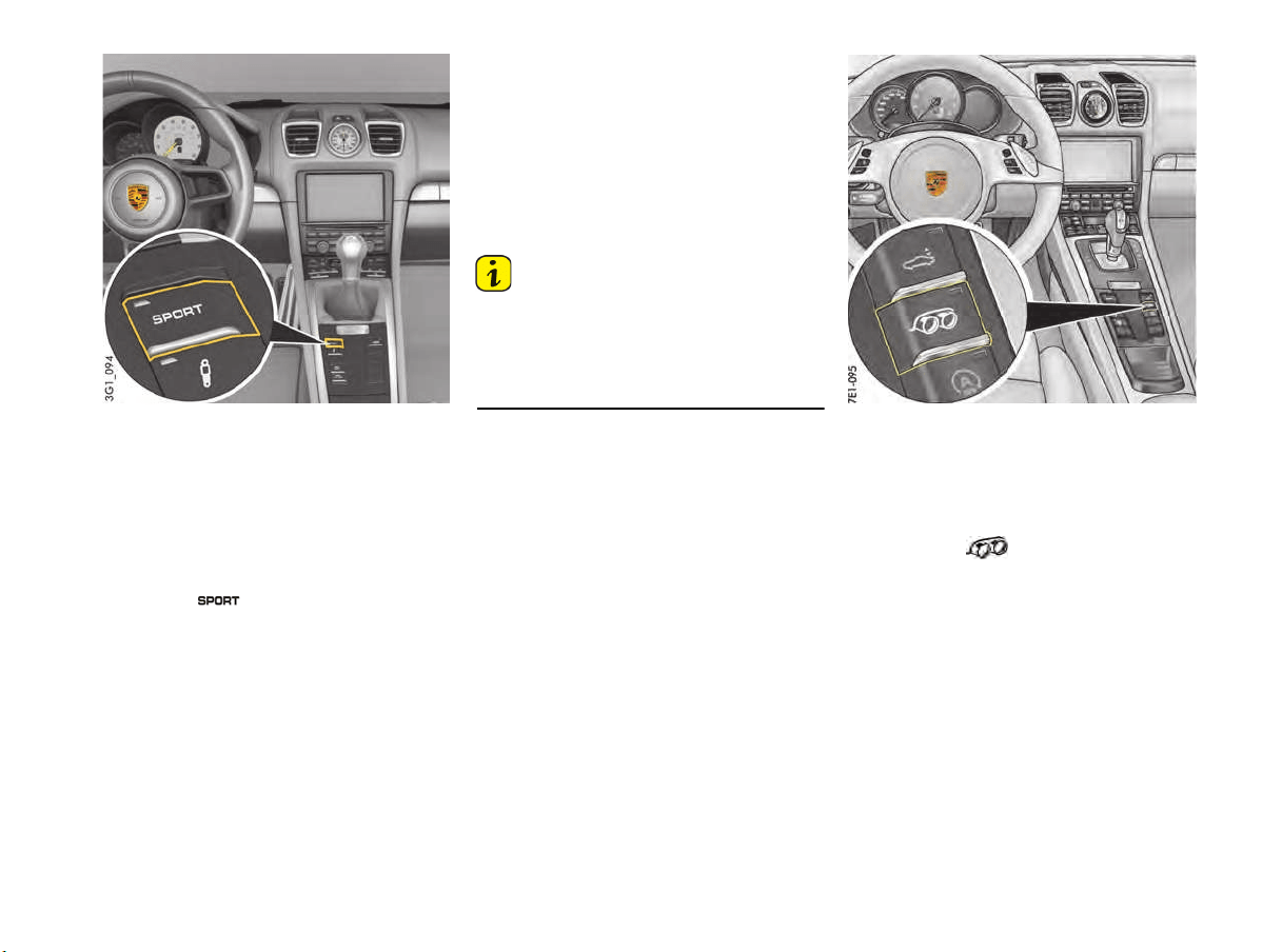
Driving and Driving Safety 141
“Sport” mode
“Sport“ mode activates the throttle-blipping
function. During downshifts, controlled revving up
ensures optimum speed compensation and
therefore greater vehicle stability during load
changes.
Switching “Sport” mode on and off
f Press the button.
When “Sport” mode is switched on, the
indicator light on the button lights up.
The word “SPORT” appears on the digital
speedometer.
Switching “Sport“ mode on end off has no
influence on the PASM mode.
Warning messages
The warning message “Sport mode not
available” appears on the multi-function display in
the instrument panel in the event of a fault.
For information on warning messages on the
multi-function display:
f Please see the chapter “OVERVIEW OF
WARNING AND INFORMATION MESSAGES”
on page 109.
Information
After the ignition is switched off, Sport mode is
automatically reset to Normal mode.
f Please see the chapter “PORSCHE ACTIVE
SUSPENSION MANAGEMENT (PASM)”
on page 139.
Sports Exhaust System
Switching on and off
The sports exhaust system can be switched to
a sound-optimized mode when the ignition is
switched on.
f Press button .
When the sports exhaust system is switched
on, the indicator light on the button lights up.

142 Storage and Luggage Compartment
Storage and Luggage Compartment
Storage .....................................................143
Drinks Holder/Cupholder .............................144
Ashtray ......................................................146
Cigarette Lighter.........................................146
Sockets .....................................................147
Front Luggage Compartment.......................148
Rear Luggage Compartment........................150
Luggage Cover...........................................150
Loading Information ....................................151
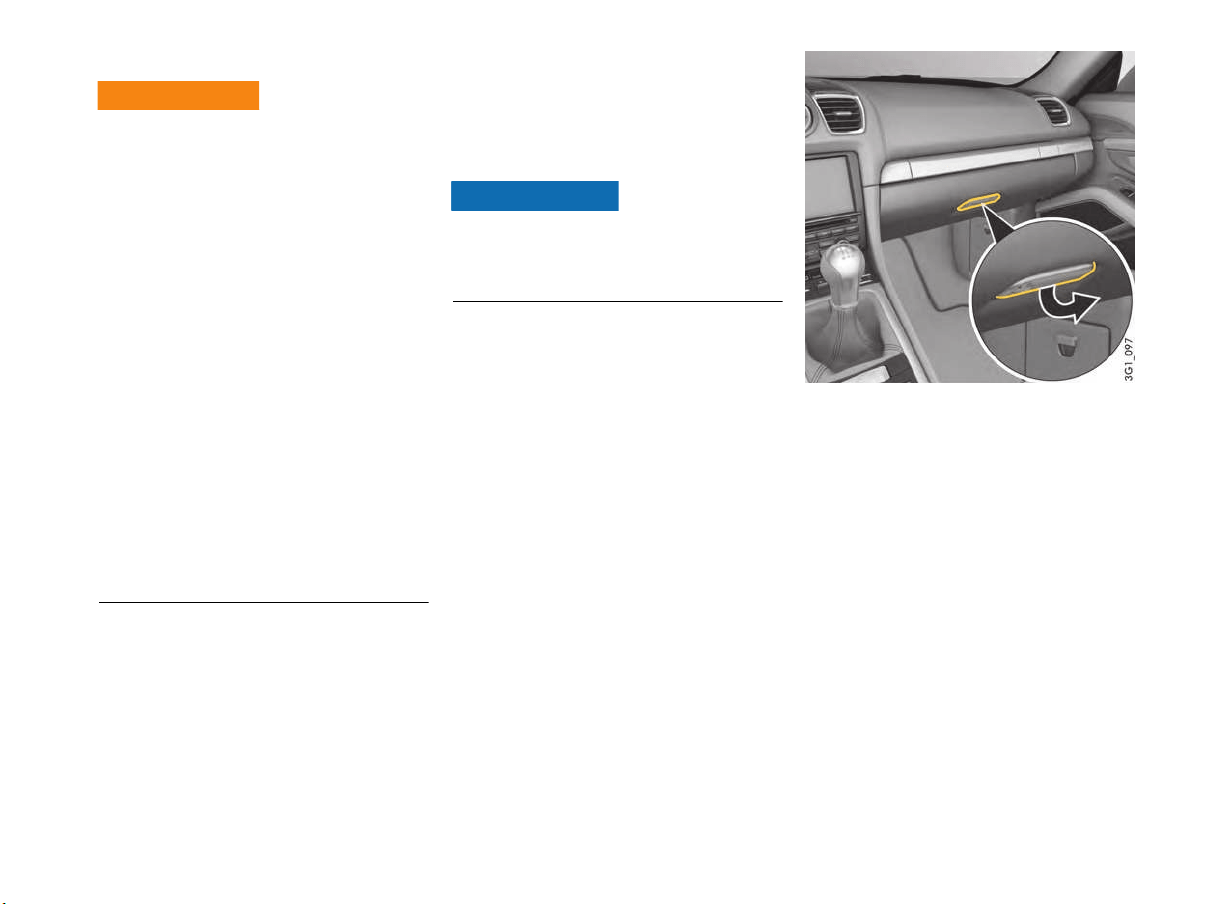
Storage and Luggage Compartment 143
Storage
An unsecured or incorrectly positioned load can
slip out of place or endanger the vehicle
occupants as a result of braking, direction
changes or in accidents.
f Do not transport items of luggage or objects
unsecured in the passenger compartment.
f Do not transport any heavy objects in open
storage trays.
f Always keep the covers of the storage trays
closed while driving.Do not exceed the
maximum gross weight and the axle load.
This information can be found under
“Technical data” in this Owner’s Manual:
Please see chapter “WEIGHTS” on page 222.
f Adapt the tire pressure to the load.
If you change the tire pressure, you must
also update the setting for Tire Pressure
Monitoring System.
Information on tire pressures for partially and
fully loaded vehicles can be found under
“Technical data” in this Owner’s Manual:
Please see chapter “TIRE PRESSURE FOR
COLD TIRES (68 °F/ 20 °C)” on page 221.
Storage options
There are various storage options available,
depending on the vehicle equipment:
– In the doors
– In the center console
– Storage net in the passenger’s footwell
Heavy and bulky objects can damage the storage
net.
f Do not place any heavy and bulky objects in the
storage net.
– Clothes hook on back of seat backrests
(depending on vehicle equipment).
– Glove box with pen holder
– Storage tray in the armrest
– Side storage trays with retractable covers
behind the seats
– Drinks holder/cupholder
Glove box
On the inside of the glove box lid, there is a holder
for clipping in a pen.
Opening
f Pull the latch handle (arrow) and open the lid.
Locking
f Always lock the latch handle with the
emergency key to secure the contents from
unauthorized access.
Unsecured, incorrectly
secured or incorrectly
positioned loads
WARNING
h
NOTICE
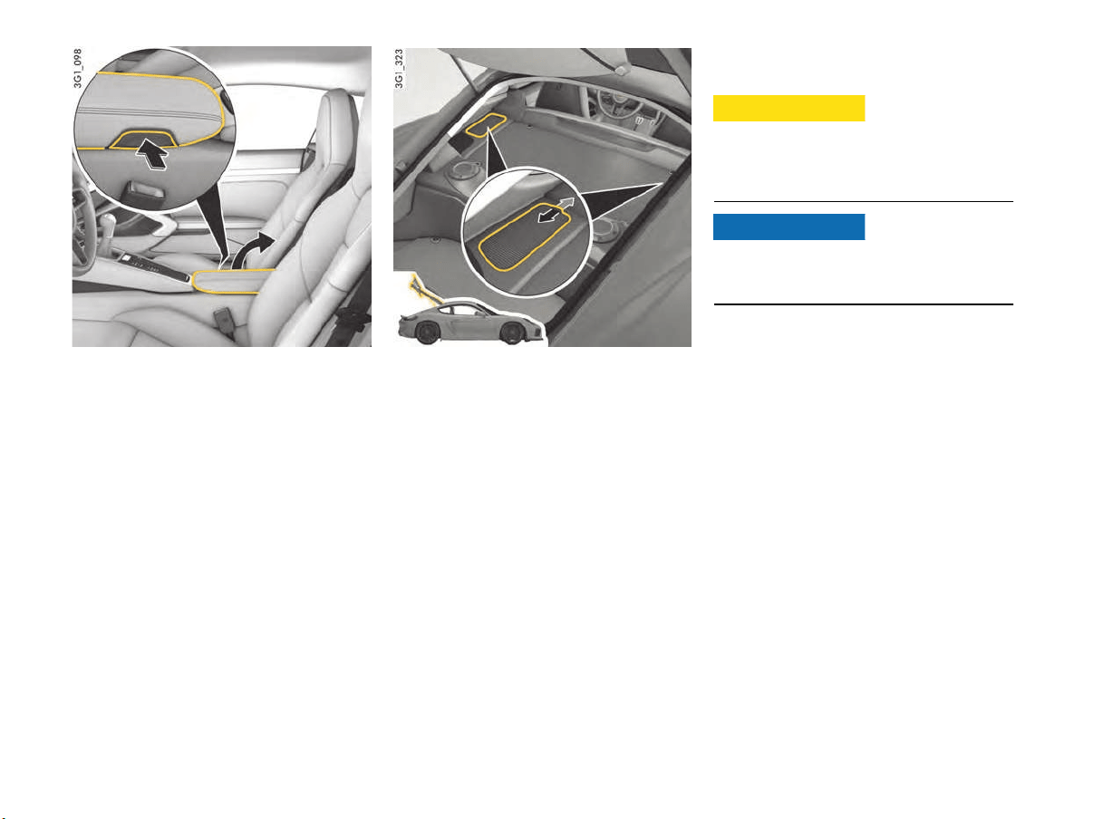
144 Storage and Luggage Compartment
Storage tray in the armrest between the
seats
Opening
f Press the button (arrow) on the passenger’s
side of the armrest.
The lid pops up automatically.
Side storage trays with retractable covers
behind the seats
Opening
f Pull the handle of the retractable cover
backwards in the direction of the arrow.
Closing
f Push the handle of the retractable cover
forwards in the direction of the arrow.
Drinks Holder/Cupholder
You can place drinks in the cupholder.
Hot drinks can cause scalding if spilt.
f Only use containers that fit.
f Never put overfull containers in the cupholder.
f Do not use hot drinks.
Risk of damage due to drinks being spilt.
f Only use containers that fit.
f Never put overfull containers in the cupholder.
Spilling hot drinks
CAUTION
h
NOTICE
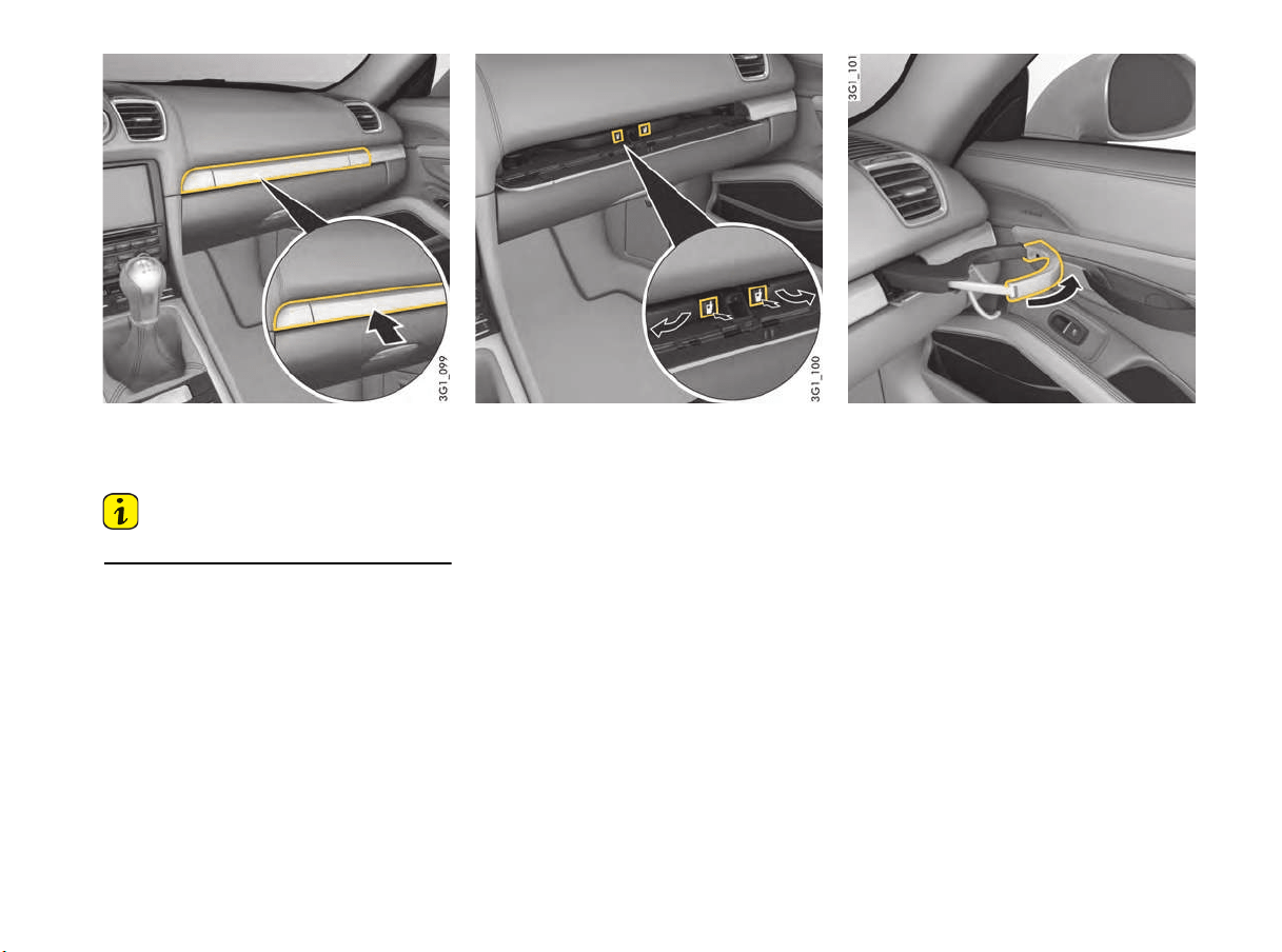
Storage and Luggage Compartment 145
Opening the cupholder
There are two folding cupholders behind the panel
above the glove box.
Information
f Keep the closed when driving.
1. Press the cupholder panel.
The panel opens.
2. Press the symbol for the left or right
cupholder.
The cupholder folds out.
3. Close the panel in the middle so that the
cupholder does not move while driving.
The cupholders can be pulled out in order to fit
larger containers.
Pulling cupholder out
1. Pull out the holder (arrow).
2. Insert a cup/container.
3. Carefully slide the holder inwards to adjust it to
the size of the cup/container.
Folding cupholder in
1. Push cupholder drawer in.
2. Open the panel in the middle.
3. Fold the cupholder in and engage it.
4. Close the panel in the middle.
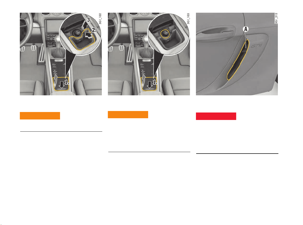
146 Storage and Luggage Compartment
Ashtray
(depending on equipment)
f Never use ashtray for waste paper disposal,
as it could pose a fire hazard.
Opening
1. Press briefly on the ashtray lid.
The lid opens automatically.
Emptying
2. To unlock, press ashtray insert forwards at the
top right until it is felt to disengage.
3. Pull the ashtray insert upwards to remove it.
f After emptying the ashtray insert, replace it
and push it downwards until it is felt to engage.
Cigarette Lighter
(depending on equipment)
The tip of the cigarette lighter becomes very hot
in use.
f Do not leave children in the vehicle unattended.
f Never touch the heating element or sides of
the lighter.
f Only hold the heated lighter by the knob.
Using the cigarette lighter
The cigarette lighter is ready for use regardless of
ignition lock position.
f For information on using charging adapters in
the cigarette lighter:
Please see chapter “USING CHARGING
ADAPTER FOR 12 VOLT SOCKET/CIGARETTE
LIGHTER” on page 147.
1. Press briefly on the ashtray lid.
2. Press the lighter into the receptacle. When the
element is red hot, the lighter will jump back to
its initial position
Cigarettes or cigars can be blown into the air
inlets A by the air flow and cause a fire in the
engine compartment.
f Do not throw burning cigarettes or cigars out
of the vehicle.
Ashtray fire risk
WARNING
h
Burns due to hot
cigarette lighter
WARNING
h
Danger of fire due to the
disposal of burning
cigars or cigarettes
DANGER
h
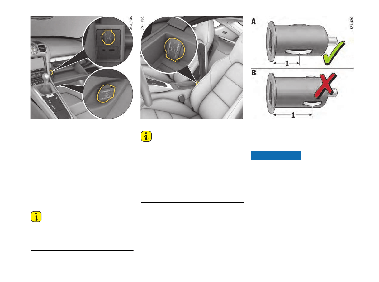
Storage and Luggage Compartment 147
Sockets in the glove box and passenger footwell
Sockets
Electrical accessories can be connected to the
12 V sockets.
Depending on the vehicle equipment, these
sockets are located in the glove box, the
passenger footwell and in the oddments tray in the
center console.
f For information on using charging adapters in
12 volt sockets:
Please see chapter “USING CHARGING
ADAPTER FOR 12 VOLT SOCKET/CIGARETTE
LIGHTER” on page 147.
Information
The maximum electrical load of a socket is 20 A,
but only if no other loads are switched on. Do not
exceed 10 A per socket if several loads are
operating simultaneously.
Center console socket
Information
The sockets and thus the connected electrical
accessories function even if the ignition is
switched off or the ignition key is removed.
If the engine is not running and the accessories
are switched on, the vehicle battery will be
discharged. The power supply is interrupted after
30 minutes to protect the vehicle battery. If the
load is to be switched on again, the ignition must
be switched on once.
A - Suitable charging adapter
B - Unsuitable charging adapter
Using charging adapter for 12 volt
socket/cigarette lighter
Risk of damage to the electrical system.
f Only use a suitable charging adapter (A) that
meets the following requirements:
The distance 1 between the ground
connection and the upper edge of the charging
adapter must be less than approx. 0.63 in.
(16 mm).
Unsuitable charging adapters (B) with a larger
distance 1 than 0.63 in. (16 mm) between the
ground connection and the upper edge can
destroy the sockets.
NOTICE
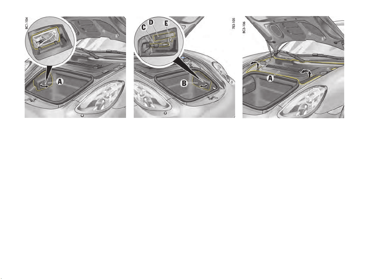
148 Storage and Luggage Compartment
Front Luggage Compartment
f Please see chapter “OPENING AND CLOSING
LUGGAGE COMPARTMENT LIDS” on page 24.
Tire sealant
The tire sealant is located in plastic box A.
f Grasp plastic box A at the handle recess and
remove.
f To insert the plastic box, first insert the tab at
the rear.
Engage the box at the front.
C - Towing lug
D - Tool kit
E - Adapter for security wheel bolts
Tools
The tools are located in a plastic box B.
f Grasp plastic box B at the handle recess and
remove.
f To insert the plastic box, first insert the tab at
the rear.
Engage the box at the front.
Tire filling compressor
Removing the tire filling compressor
1. Lift plastic cover A at the handle recesses
(arrows) until the clips are heard to disengage
and pull forwards slightly.
2. Lift the plastic cover at front.
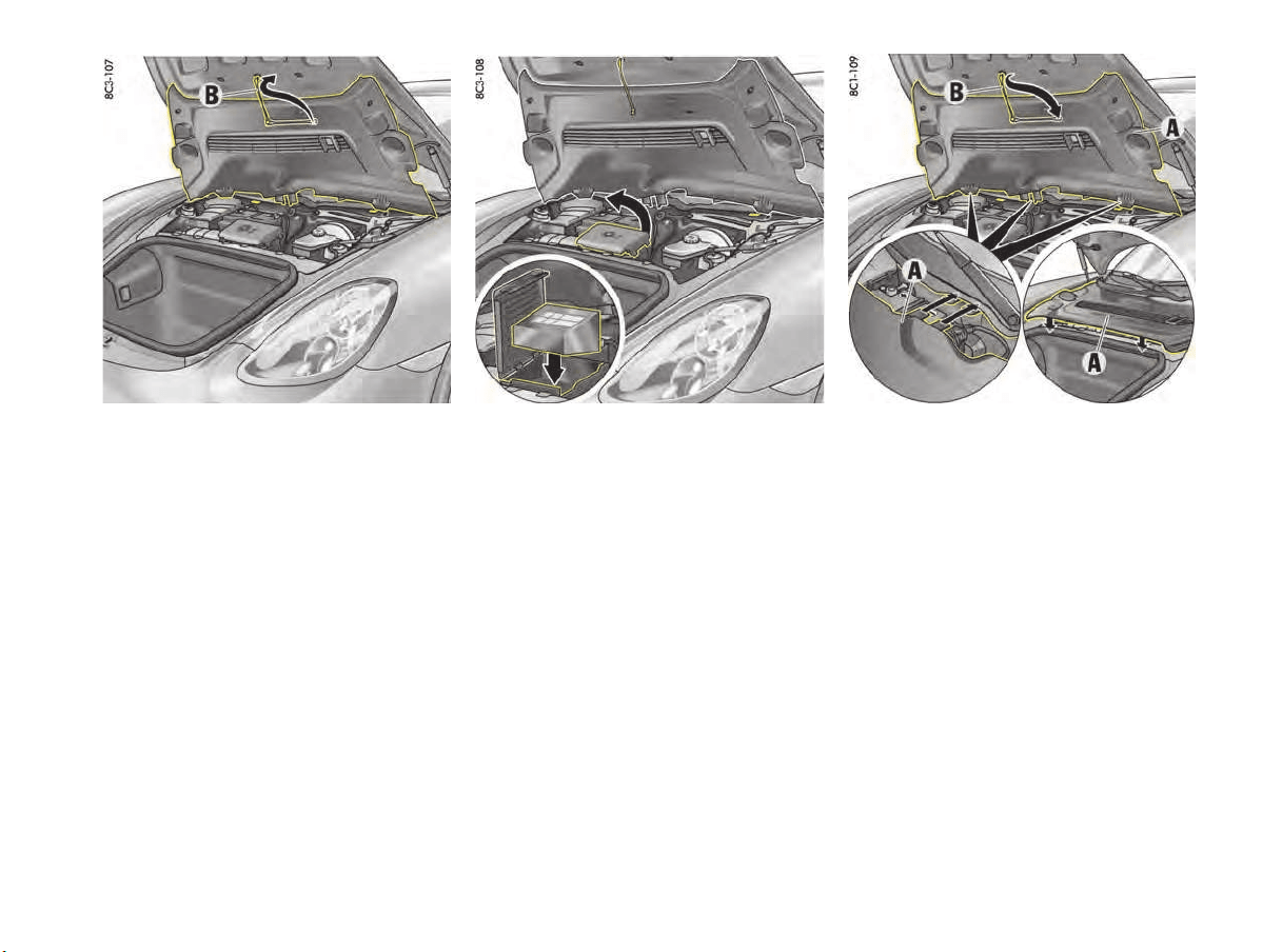
Storage and Luggage Compartment 149
3. retaining strap B on the underside of the
plastic cover and attach to the luggage
compartment lid.
4. Open the cover of the storage compartment
for the tire filling compressor.
5. Remove the tire filling compressor from the
storage compartment.
Stowing the tire filling compressor
1. The tire filling compressor is wedge-shaped.
Insert the tire filling compressor in the storage
compartment so that the narrower side faces
forwards (illustration).
2. Close the cover of the storage compartment
for the tire filling compressor.
3. Detach retaining strap B and clip onto the
plastic cover.
4. Insert plastic cover A with the guides at the
rear edge and lay it on the yellow holder. Lower
the plastic cover at the front.
5. Ensure that the centring pins on the underside
of the cover engage in the guide.
Press the cover downwards at the handle
recesses, until the clips are heard to engage.
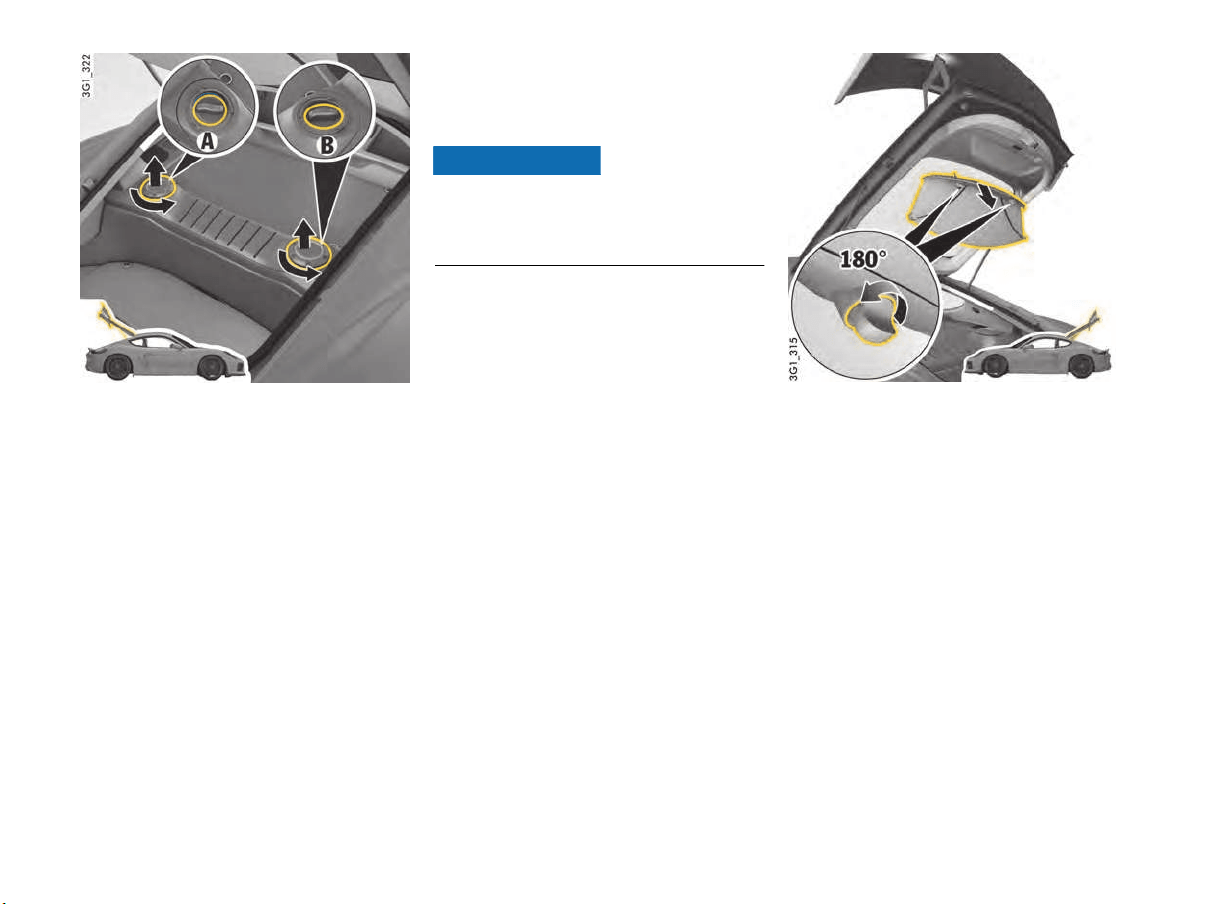
150 Storage and Luggage Compartment
A - Topping up coolant
B - Topping up engine oil
Rear Luggage Compartment
The refilling points for coolant A and engine oil B
are located in the rear luggage compartment.
f Please see chapter “CHECKING THE COOLANT
LEVEL AND ADDING COOLANT” on page 184.
f Please see chapter “TOPPING UP ENGINE OIL”
on page 166.
Luggage Cover
The luggage cover protects luggage in the rear
storage area from direct sunlight and curious
eyes.
Risk of damage to luggage cover from
sharp-edged or sliding pieces of luggage.
f Always remove luggage cover if pieces of
luggage might damage the luggage cover.
Removing the luggage cover
1. Hold luggage cover with one hand and loosen
both turn-locks.
2. Remove the luggage cover using both hands.
NOTICE
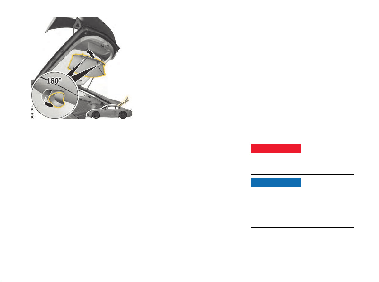
Storage and Luggage Compartment 151
Installing the luggage cover
f Place luggage cover into the mounting with
both hands, hold it with one hand and lock both
turn-locks.
Loading Information
Definitions
The rear-axle load is the vehicle weight on the
rear axle plus the weight of the transported load.
The Curb weight – actual weight of your vehicle -
vehicle weight including standard and optional
equipment, fluids, and emergency tools. This
weight does not include passengers and cargo.
The Gross Vehicle Weight is the sum of the curb
weight and the weight of passengers and cargo
combined.
The Gross Vehicle Weight Rating is the
maximum total weight of vehicle, passengers,
luggage and optional equipment.
The Gross Axle Weight Rating is the maximum
load limit for the front or the rear axle. This
information is located on the safety compliance
sticker located in the driver’s side door aperture
area.
For determining the compatibility of the tire and
vehicle load capabilities:
f Please see chapter “TIRES AND WHEELS” on
page 186.
The load capacity coefficient (e.g. “106”) is a
minimum requirement. For more information:
f Please see chapter “INSCRIPTION ON RADIAL
TIRE” on page 194.
The Gross Combined Weight Rating is the
maximum total weight rating of vehicle,
passengers and cargo.
The Vehicle Capacity Weight – Load Limit - is
the maximum total weight limit specified of the
load (passengers and cargo) for the vehicle. This
is the maximum weight of passengers and cargo
that can be loaded into the vehicle. This infor-
mation can be found on the tire pressure plate.
The maximum loaded vehicle weight is the
sum of curb weight, accessory weight, vehicle
capacity weight and production options weight.
The load rating is the maximum load that a tire
is rated to carry for a given inflation pressure.
The maximum load rating is the load rating for
a tire at the maximum permissible inflation
pressure.
The cargo capacity is the permissible weight of
cargo, the subtracted weight of passengers from
the load limit.
Overloading will lead to dangerous vehicle
reactions and long braking distances.
f Never exceed the specified axle loads.
Risk of damage to the vehicle if the vehicle is
overloaded.
Overloading can shorten the service life of the
tires and car. Damage due to overloading is not
covered by the vehicle warranty.
f Never exceed the specified axle loads.
Overloading vehicle
DANGER
h
NOTICE
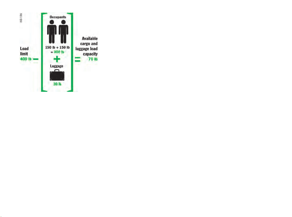
152 Storage and Luggage Compartment
Example for determining the combined weight of
occupants and cargo
Vehicle Load Capacity
f The combined weight of occupants and cargo
should never exceed the weight shown on the
tire pressure plate in the vehicle.
Please see chapter “TIRE PRESSURE PLATE”
on page 189.
f Never exceed the number of passengers
shown on the tire pressure plate in the vehicle.
Determining the combined weight of
occupants and cargo:
f Add the weight of all occupants and then add
the total luggage weight (figure).
Steps for determining correct load limit
1. Locate the statement “The combined weight of
occupants and cargo should never exceed XXX
pounds” on your vehicle’s placard (depending
on the date of manufacture).
2. Determine the combined weight of the driver
and passengers that will be riding in your
vehicle.
3. Subtract the combined weight of the driver and
passengers from XXX kilograms or XXX
pounds.
4. The resulting figure equals the available
amount of cargo and luggage load capacity.
For example, if the “XXX” amount equals 400
lbs. and there will be two - 150 lb passengers
in your vehicle, the amount of available cargo
and luggage load capacity is 100 lbs. [400 -
300 (2 x 150) = 100 lbs.].
5. Determine the combined weight of luggage
and cargo being loaded on the vehicle. That
weight may not safely exceed the available
cargo and luggage load capacity calculated in
Step 4.

Parking 153
Parking
Garage Door Opener HomeLink
®
(Universal Remote Control)...........................154
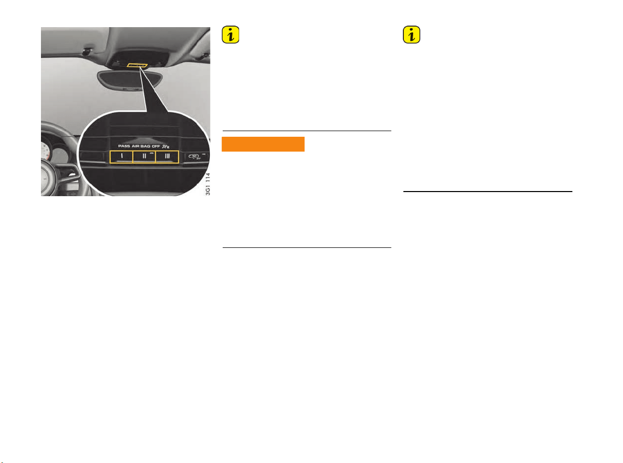
154 Parking
Garage Door Opener HomeLink
®
(Universal Remote Control)
With the HomeLink
®
of your Porsche, a wide
range of remote-controlled equipment
(e.g. garage door/gate to your property, security
systems, house lights) can be activated from
inside the vehicle.
The HomeLink
®
system replaces up to three
different original remote controls. The signal for
a remote control can be assigned to one of the
three memory buttons I, II and III on the overhead
operating console keypad. The respective
equipment can then be operated using the
programed memory button.
Transmission of the signal is indicated by the
indicator light in the button II.
Information
f Please read the instructions for the original
remote control.
f Information on the compatibility of your
vehicle’s HomeLink
®
system with the original
remote control can be obtained from your
authorized Porsche dealer, on the HomeLink
®
website (www.homelink.com) or by calling the
free HomeLink
®
hotline (1-800-355-3515).
When opening and closing the equipment being
operated, parts of the body could become
trapped or crushed.
f When using the garage door opener, make
sure that no persons or animals are within the
range of movement of the equipment that is
being operated.
f Observe the safety notes for the original
remote control.
Information
f When the button is pressed, the transmitter
unit sends the signal forward in direction of
travel.
Always align the vehicle with the receiver.
Otherwise, range restrictions cannot be ruled
out.
f Before selling the vehicle, delete the
programed signals for the garage door opener
on the keypad.
f If the equipment cannot be operated after the
initial programing, check whether the original
remote control has fixed or changeable code.
To find this out, read the instructions for the
original remote control.
Garage door opener use
WARNING
h
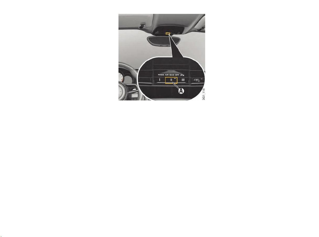
Parking 155
Operating the garage door opener
The ignition must be switched on.
f Press and hold the corresponding HomeLink
®
button on the overhead operating console
keypad.
The indicator light A lights up during signal
transmission.
Programing garage door opener: Deleting
and storing signals
The HomeLink
®
system is programed on
the overhead operating console and in direct
proximity to the vehicle’s radiator grille.
Preconditions
In order to delete programed signals and
store garage door opener signals,
– the ignition must be switched on,
– the turn signals must be off and
– the engine must be off.
When using the garage door opener, the vehicle
must be within the range of the receiver.
Deleting programed signals from the buttons
This process clears all of the HomeLink
®
programing. It is not possible to individually clear
the programed buttons.
Do not repeat this process if you want to assign
additional signals to the buttons.
f Keep the two outer buttons I and III on the
overhead operating console keypad pressed
for approx. 20 seconds until the indicator
light A on button II starts to flash quickly.
f Release the buttons.
The HomeLink
®
buttons are cleared and can be
reprogramed.
Assigning garage door opener signal to key
with fixed code system
On the overhead operating console:
1. Switch on ignition.
2. The standard factory-set codes must be
deleted before programing for the first time.
3. Press and hold the desired button on the
overhead operating console keypad until the
indicator light A on button II starts to flash
slowly.
You now have 5 minutes to teach the button.
4. Stand in front of the vehicle with the original
remote control of the system to be
programed.
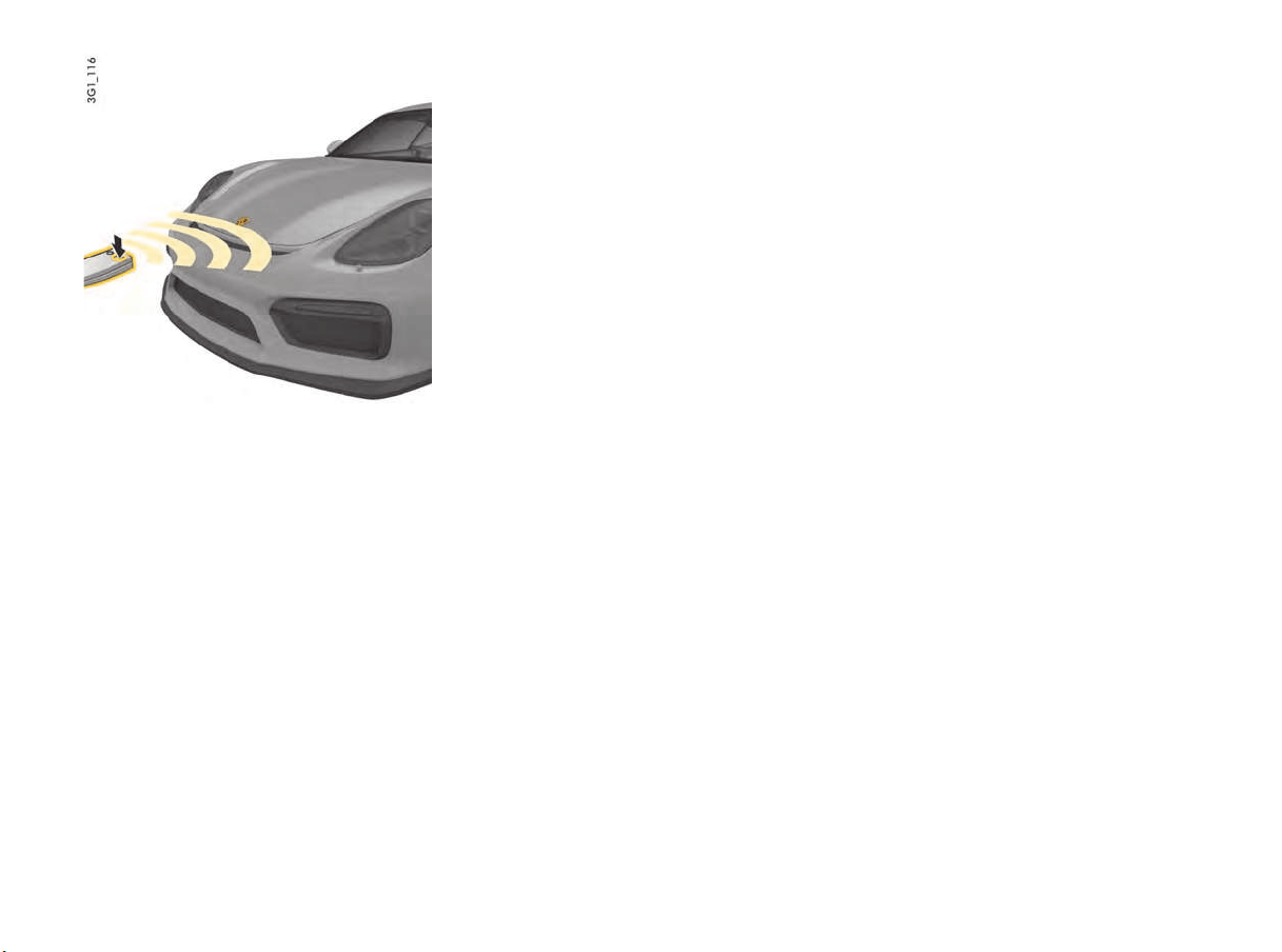
156 Parking
In front of the vehicle:
5. Hold the original r
emote control approx. 12 in.
(30 cm) away from the marked position
(illustration) and press and hold the transmit
button (for more than approx. 1 minute in
some cases) until the vehicle’s turn signal
lights flash on and off three times or the
indicator light A on the overhead operating
console starts flashing quickly.
The turn signal lights flash three times and the
indicator light A flashes quickly to confirm that
the new signal has been programed
successfully.
Several attempts with different distances
between the vehicle and the original remote
control may be necessary.
With some systems, the transmit button on the
original remote control may need to be
pressed again when the indicator light on the
original remote control goes out.
6. The turn signal lights will flash once when the
5 minute teaching readiness period has
elapsed.
Repeat steps 3 to 5.
7. Repeat steps 3 to 5 to assign further signals
to the remaining buttons.
Assigning garage door opener signal to
button with changeable code system
With some systems, a changeable code also
needs to be programed for the HomeLink
®
system. A second person makes programing
easier.
Identifying the changeable code
f Press and hold the previously programed
HomeLink
®
button.
If the indicator light A on button II in the overhead
operating console starts to flash quickly and lights
up continuously after approx. 2 seconds, it means
that the equipment has a changeable code
system.
f Information on synchronization can also be
found in the operating instructions for the
system to be programed.
Assigning garage door opener signal to key
f Park the vehicle within the range of the remote-
controlled equipment.
On the overhead operating console:
1. Switch on ignition.
2. The standard factory-set codes must be
deleted before programing for the first time.
For information on deleting the factory-set codes:
f Please see the chapter “PROGRAMING
GARAGE DOOR OPENER: DELETING AND
STORING SIGNALS” on page 155.
3. Press and hold the desired button on the
overhead operating console keypad until the
indicator light A on button II starts to flash
slowly.
You now have 5 minutes to teach the button.
4. Stand in front of the vehicle with the original
remote control of the system to be
programed.
In front of the vehicle:
5. Hold the original remote control approx. 12 in.
(30 cm) away from the marked position
(illustration) and press and hold the transmit
button (for more than approx. 1 minute in
some cases) until the vehicle’s turn signal
lights flash on and off three times or the
indicator light A on the overhead operating
console starts flashing quickly.
The turn signal lights flash three times and the
indicator light A flashes quickly to confirm that
the new signal has been programed
successfully.
Several attempts with different distances
between the vehicle and the original remote
control may be necessary.
With some systems, the transmit button on the
original remote control may need to be
pressed again when the indicator light on the
original remote control goes out.

Parking 157
6. The turn signal lights will flash once when the
5 minute teaching readiness period has
elapsed.
Repeat steps 3 to 5.
7. Repeat steps 3 to 5 to assign further signals
to the remaining buttons.
8. Locate the programing button on the receiver
of the equipment to be programed, e.g. on
the motor unit of the garage door opener.
Synchronizing the system
9. Activating the motor unit:
Press the programing button on the receiver
of the garage door opener.
You then usually have approx. 30 seconds to
initiate step 10 (a setting indicator is usually
activated on the motor unit).
10. Programing on the overhead operating
console:
Press the button you selected in step 3 three
times on the overhead operating console
keypad (you must press the button on the
keypad several times to complete the setting
process for some devices).
11. Repeat steps 3 to 10 to assign signals to the
other buttons.
12. After completing programing on the overhead
operating console, the system should
recognize the HomeLink
®
signal and launch
as soon as the memory button is pressed
when the ignition is switched on.
Reprograming an individual button on the
keypad
A HomeLink
®
button can be individually
reprogramed without deleting the rest of the
button assignments.
On the overhead operating console:
1. Switch on ignition.
2. Press and hold the button to be programed on
the overhead operating console keypad
(approx. 20 seconds), until indicator light A on
button II flashes slowly.
You now have 5 minutes to teach the button.
3. Stand in front of the vehicle with the original
remote control of the system to be
programed.
In front of the vehicle:
4. Hold the original remote control approx. 12 in.
(30 cm) away from the marked position
(illustration) and press and hold the transmit
button (for more than approx. 1 minute in
some cases) until the vehicle’s turn signal
lights flash on and off three times or the
indicator light A in the overhead operating
console starts to flash quickly.
The turn signal lights flash three times and the
indicator light A flashes quickly to confirm that
the new signal has been programed
successfully.
Several attempts with different distances
between the vehicle and the original remote
control may be necessary.
With some systems, the transmit button on the
original remote control may need to be
pressed again when the indicator light on the
original remote control goes out.
5. The turn signal lights will flash once when the
5-minute teaching readiness period has
elapsed.
Repeat steps 1 to 4.
6. Repeat steps 1 to 4 to assign further signals
to the other buttons.
Information
f Please consult an authorized Porsche dealer if
you have not been able to successfully assign
signals to the buttons even though you have
carefully followed the instructions in this
section and the operating instructions for the
original remote control. Your authorized
Porsche dealer has a list of all garage door
opener signals that can be adapted.
f Make sure that the battery in the remote
control for the garage door opener is new.
If the battery voltage is inadequate, faults may
occur in signal transmission. The system in the
vehicle then learns the wrong code, which will
not be recognized reliably by the garage door
opening mechanism.

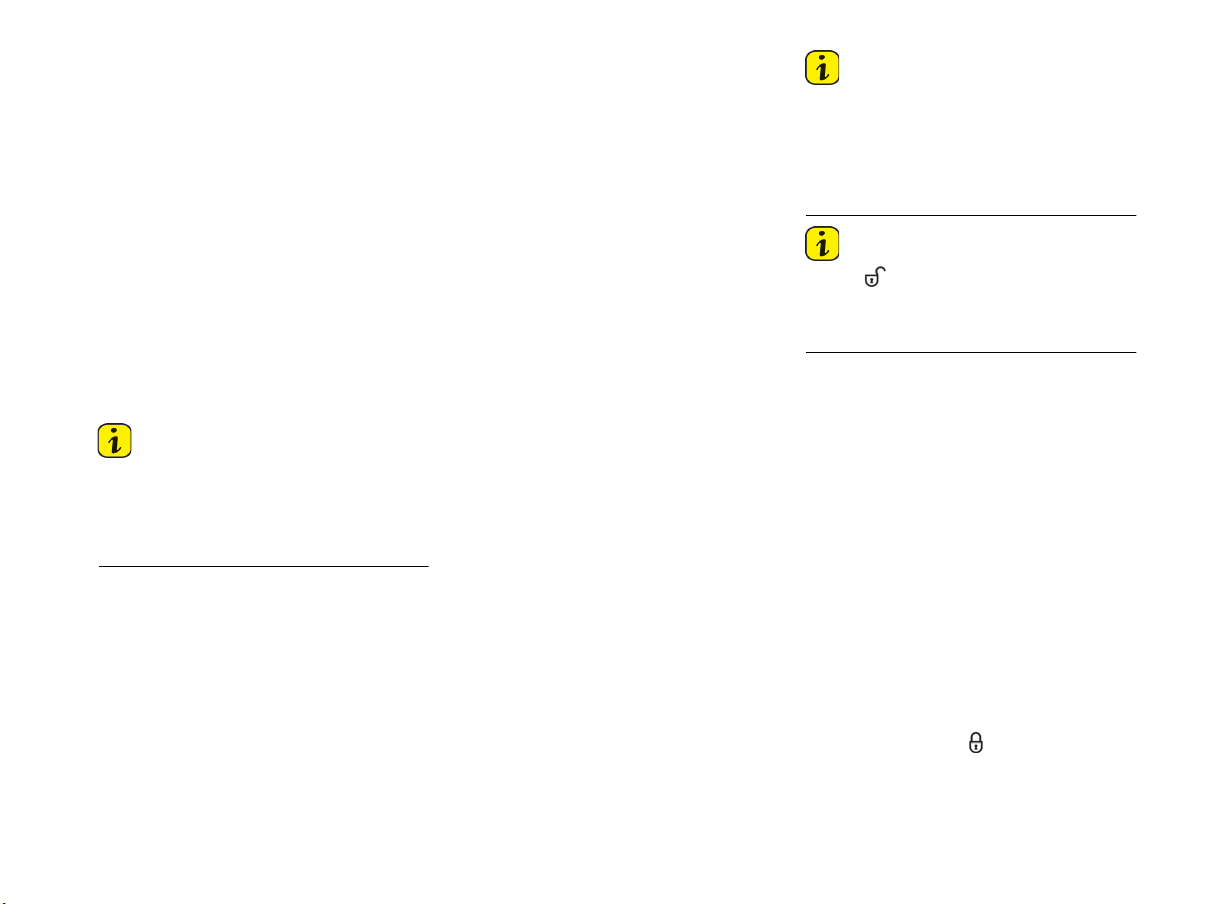
Alarm System and Theft Protection 159
Alarm System and Passenger
Compartment Monitoring
FCC Numbers:
This device complies with Part 15 of the FCC
Rules and RSS-210 of Industry Canada.
Operation of this device is subject to the following
two conditions:
1. This device may not cause harmful
interference, and
2. this device must accept any interference
received including interference that may cause
undesired operation.
Changes or modifications not expressly approved
by the party responsible for compliance could void
the user's authority to operate the equipment.
Information
The manufacturer is not responsible for any radio
or TV interference caused by unauthorized
modifications to this equipment.
Such modification could void the user's authority
to operate the equipment.
The alarm system monitors the following alarm
contacts:
– Alarm contacts in doors, luggage
compartment lids and headlights.
– Interior surveillance: Movement in the interior
when the vehicle is locked, e.g. attempted
theft after breaking a window.
– Inclination sensor country-specific equipment:
inclination of the vehicle (e.g. when attempting
to tow).
If one of these alarm contacts is interrupted,
the alarm horn sounds for approx. 30 seconds
and the emergency flasher flashes.
After 5 seconds of interruption, the alarm is
triggered again. This cycle is repeated up to ten
times.
Switching on
f The alarm system is activated when the vehicle
is locked.
Switching off
f The alarm system is deactivated when the
vehicle is unlocked.
Information
f If you unlock the vehicle with the emergency
key in the door lock, you must switch the
ignition on (ignition lock position 1) within
10 seconds of opening the door in order to
prevent the alarm system from being
triggered.
Information
If button on the vehicle key is pressed and a
door or a luggage compartment lid is not opened,
the vehicle is locked again automatically after 30
seconds.
Switching off the alarm system if it is
triggered
f Unlock vehicle or
switch on ignition.
Switching off interior surveillance and
inclination sensor
If people or animals are remaining in the locked
vehicle or the vehicle is being transported on,
e.g. a train or ship, the interior surveillance
system and inclination sensor must be switched
off temporarily.
f Please see the chapter “LOCKING DOORS”
on page 22.
f Inform any persons remaining in the vehicle
that the alarm system will be triggered if the
door is opened.
Using the vehicle key
f Quickly press button on the vehicle key
twice within 2 seconds. The emergency
flasher flashes slowly once.The doors are
locked, but can be opened from inside.
USA: KR55WK50138
Canada: 7812D-5WK50138

160 Alarm System and Theft Protection
Information
The interior surveillance system and inclination
sensor r
emain switched off if:
– The interior surveillance system and inclination
sensor were switched off when you last locked
the vehicle
and
If button A was pressed and a door or a
luggage compartment lid was not opened.
Function indication
The locking condition of the vehicle is indicated by
the indicator lights in the central locking button
flashing at different frequencies.
The indicator lights go out when the vehicle is
unlocked.
The locking condition of the vehicle is indicated by
the indicator lights in the doors flashing at
different frequencies.
Alarm system is activated
– The indicator lights flash quickly twice when
the vehicle is being locked, then flash normally.
Alarm system is activated, interior
surveillance and inclination sensor are
switched off
– The indicator lights flash quickly while you are
locking the vehicle, go out for 10 seconds and
then flash normally.
Faults in the central locking system and
alarm system
The indicator lights come on for 10 seconds, flash
at double speed for 20 seconds and then flash
normally.
Avoiding false alarms
f If people or animals are remaining in the locked
vehicle or the vehicle is being transported on
a train or ship, for example, the interior
surveillance system and inclination sensor
must be switched off temporarily.
f Always close all door windows.
Immobilizer
There is a transponder (an electronic component),
containing a stored code, in each key.
Before the ignition is switched on, the ignition lock
checks the code.
The immobilizer can be deactivated and the
engine started using an authorized ignition
key only.
Theft Protection
When leaving the vehicle, always:
f Close the windows.
f Activate the electric parking brake.
f Remove the ignition key
f Close the glove box.
f Close all storage compartments.
f Remove valuables, vehicle registration
documents, telephone and house keys from
the vehicle.
f Close the luggage compartment lids.
f Lock the doors.

Maintenance and Car Care 161
Maintenance and Car Care
Exercise Extreme Caution when
Working on your vehicle...............................162
Engine Oil...................................................165
Checking Engine Oil Level ............................165
Topping up Engine Oil..................................166
Washer Fluid ..............................................167
Wiper Blades ..............................................168
Emission Control System.............................168
How Emission Control Works .......................169
Fuel Economy .............................................170
Operating Your Porsche in other Countries....170
Fuel ...........................................................171
Portable Fuel Container ...............................173
Fuel Recommendations................................173
Fuel Evaporation Control .............................174
Car Care Instructions...................................174

162 Maintenance and Car Care
Exercise Extreme Caution when
Working on your vehicle
The engine compartment of any motor vehicle is a
potentially hazardous area. If you are not fully
familiar with proper repair procedures, do not
attempt the adjustments described on the
following pages.
This caution applies to the entire vehicle.
Many vehicle fluids are highly flammable, e. g.
fuel, engine and transmission oil. Fuel vapors can
cause an explosion. When a battery is being
charged, highly explosive gases can develop.
f Do not smoke or allow an open flame around
the battery or fuel.
Pay attention to sparks, e. g. when coming into
contact with cables.
Keep a fire extinguisher close at hand.
f Ensure that there are no open flames in the
area of your vehicle at any time when fuel
fumes might be present. Be especially
cautious of devices such as hot water heaters
which ignite a flame intermittently.
f Only work on your vehicle outdoors or in a well
ventilated area.
Refill fluids, e. g. engine oil, brake fluid or coolant
are hazardous to health (poisonous, irritant,
caustic).
f Keep these fluids out of children's reach and
dispose of them in accordance with the
appropriate State, Local and Federal
regulations.
f Only work on your vehicle outdoors or in a well
ventilated area.
Engine exhaust is dangerous if inhaled.
Engine exhaust fumes have many components
which you can smell. They also contain carbon
monoxide (CO), which is a colorless and odorless
gas.
Carbon monoxide can cause unconsciousness
and even death if inhaled.
f Only work on your vehicle outdoors or in a well
ventilated area.
The engine and surrounding components, exhaust
system and coolant become very hot when the
engine is running.
The coolant reservoir is pressurized. Careless
opening of the coolant reservoir can lead to hot
coolant suddenly spraying out.
f Take care when working near hot parts of the
vehicle, in particular engine parts and parts of
the exhaust system.
f Before working in the engine compartment,
always switch the engine off and let it cool
sufficiently.
f Allow the engine to cool down before opening
the cap of the coolant reservoir and protect
your hands, arms and face from any possible
escape of hot coolant.
Take great care to ensure that hands, fingers,
articles of clothing (e. g. ties, sleeves, etc.),
necklaces or long hair cannot be caught up by the
radiator fans, drive belt or other moving parts.
The radiator fans in the front of the vehicle may be
operating or unexpectedly start operating when
the engine is switched on.
f Exercise extreme care that parts of the body,
articles of clothing or jewelry do not get caught
in the radiator fan, drive belt or other moving
parts.
f Carry out work in these areas only with the
engine off and exercise extreme caution.
When the ignition is on, all cables and wires of the
ignition system carry a high voltage.
f Exercise special care when working on the
ignition system.
Fire and explosion
hazar
ds
DANGER
h
Fluid health hazards
Exhaust gas inhalation
Hot engine parts,
exhaust system and
fluids
WARNING
h
WARNING
h
WARNING
h
Moving engine parts
Electric shock from
ignition system
WARNING
h
WARNING
h

Maintenance and Car Care 163
If the vehicle is not secured, or incorrectly
secured, during repair work, it could move
unexpectedly or fall from the car jack or car lift.
f Be alert and cautious around the engine at all
times while it is running.
If you have to work on the engine while it is
running, always apply the electric parking
brake.
f Always support your car with safety stands if it
is necessary to work under the car. The jack
supplied with the car is not adequate for this
purpose.
Switch off level control of air suspension and
height adjustment.
Please see the chapter “RAISING THE VEHICLE
WITH A LIFTING PLATFORM, TROLLEY JACK
OR STANDARD JACK” on page 195.
f Jack up the vehicle only at the specified
jacking points on the underside of the vehicle.
f Never start the engine when the vehicle is
jacked or lifted up. Vibration from the engine
could cause the vehicle to fall.
f When working under the car without safety
stands but with the wheels on the ground,
make sure the car is on level ground, the
wheels are blocked, and that the engine
cannot be started. Withdraw ignition keys.
Information
f Incomplete or improper servicing may cause
problems in the operation of the car. If in doubt
about any servicing, have it done by your
authorized Porsche dealer.
Improper maintenance during the warranty
period may affect your Porsche warranty
coverage.
f Some countries require additional tools and
special spare parts to be carried in your
vehicle. Please make enquiries before driving
abroad.
Technical Modifications
f Modifications may be carried out on your
vehicle only if approved by Porsche.
This ensures that your Porsche will remain
reliable and safe to drive, and that it will not be
damaged as a result of the modifications.
Your authorized Porsche dealer will be pleased
to advise you.
Information
f Only use genuine Porsche spare parts for your
vehicle or spare parts of similar quality which
have been manufactured according to the
specifications and production requirements of
Porsche. These parts are available from your
authorized Porsche dealer. Safety-related
accessories should only be used if they are
from the Porsche Tequipment range or are
tested and approved by Porsche. Your
authorized Porsche dealer will be pleased to
advise you and answer any questions you may
have.
However, the use of other parts or
accessories may adversely affect the safety
of your vehicle, and Porsche can take no
responsibility for any loss or damage caused
by their use.
Even if the supplier of other accessories or
parts is a recognized supplier, the safety of
your vehicle may still be affected if such items
are installed.
Due to the large variety of products offered in
the accessory market, it is not possible for
Porsche to inspect and approve every one.
f In addition, please note that the use of
replacement parts that are not genuine
Porsche parts or approved parts, or the use of
accessories not approved by Porsche may
also detrimentally affect your vehicle warranty.
f Check your vehicle regularly for signs of
damage. Damaged or missing aerodynamic
components, such as spoilers or underbody
panels, impair vehicle handling and must
therefore be replaced immediately.
Failure to secure vehicle
WARNING
h

164 Maintenance and Car Care
Radiator fan, engine compartment
blowers
The engine-compartment blowers are mounted in
the engine compartment.
After the engine is switched off, the engine
compartment temperature is monitored for
approx. 30 minutes.
During this period, and depending on
temperature, the engine-compartment blowers
may continue to run or start to run.
f Carry out work in this area only with the engine
off and exercise extreme caution.
The radiators and radiator fans are in the front of
the vehicle.
The radiator fans in the front of the vehicle may be
operating or unexpectedly start operating when
the engine is switched on.
f Carry out work in these areas only with the
engine switched off.
f Take great care to ensure that parts of the
body, items of clothing or jewellery cannot be
drawn in by the radiator fan, engine-
compartment blower, drive belt or other
moving parts.
Measurements on test stands
Performance test
Performance tests on roller-type test stands are
not approved by Porsche.
Brake tests
Brake tests must be performed only on roller-type
test stands.
The following limit values must not be exceeded
on roller-type test stands:
– Test speed 4.7 mph (7.5 km/h)
– Test duration 20 seconds
In order to fulfil legal stipulations, measurements
with different limit values are permissible (e. g.
exhaust emissions tests etc.).
Testing the electric parking brake
Electric parking brake tests on the brake test
stand must only be performed with the ignition
switched on and with the manual gearshift lever in
neutral
The vehicle switches automatically to brake test
stand mode, in which the electric parking brake
can be tested.
The message “Electric parking brake in
service mode” appears on the multi-function
display in the instrument panel.
Balancing wheels on the vehicle
During finish balancing of the wheels, the entire
vehicle must be lifted and the wheels must be free
to turn.
Radiator fans, engine
compar
tment blowers
WARNING
h

Maintenance and Car Care 165
Engine Oil
It is important to perform oil changes regularly in
accordance with the intervals specified in your
Maintenance Schedule.
Engine oil consumption
It is normal for your engine to consume oil.
The rate of oil consumption depends on the quality
and viscosity of oil, the speed at which the engine
is operated, the climate, road conditions as well
as the amount of dilution and oxidation of the
lubricant.
If the vehicle is used for repeated short trips, and
consumes a normal amount of oil, the engine oil
measurement may not show any drop in the oil
level at all, even after 600 miles (1000 km) or
more. This is because the oil is gradually
becoming diluted with fuel or moisture, making it
appear that the oil level has not changed.
The diluting ingredients evaporate out when the
vehicle is driven at high speeds, as on an
expressway, making it then appear that oil is
excessively consumed after driving at high
speeds.
If the conditions you drive your vehicle in are
dusty, humid, or hot, the frequency of the oil
change intervals should be greater.
If the vehicle is driven at a high rate of speed,
climatic conditions are warm, and the load is high,
the oil should be checked more frequently, as
driving conditions will determine the rate of oil
consumption.
– The engine in your vehicle depends on oil to
lubricate and cool all of its moving parts.
Therefore, the engine oil should be checked
regularly and kept at the required level.
– Make it a habit to have the engine oil level
checked with every refueling.
– The oil pressure warning light is not an oil level
indicator.
The oil pressure warning light indicates serious
engine damage may be occuring when lit, if
engine rpm is above idle speed.
Checking Engine Oil Level
f Check the oil level on the multi-function display
at regular intervals before refueling.
f Please see the chapter “DISPLAY AND
MEASUREMENT OF THE ENGINE OIL LEVEL”
on page 82.
Engine oil is hazardous to your health and may be
fatal if swallowed.
f Keep engine oil out of children's reach.
Used engine oil contains chemicals that have
caused cancer in laboratory animals.
f Always protect your skin by washing
thoroughly with soap and water.
If you suspect an oil leak in the engine have your
authorized Porsche dealer check it out
immediately.
Top-up quantity
The difference between the minimum and
maximum marks on the segment display is
approx. 1.8 quarts (1.7 liters).
f Never add more engine oil than required to
reach the maximum mark.
If the oil level is too low, this is indicated by the
oil-warning light on the multi-function display.
f Add engine oil immediately.
f Please see the chapter “OVERVIEW OF
WARNING AND INFORMATION MESSAGES”
on page 109.
Swallowing engine oil
Engine oil cancer risk
Oil-level warning
DANGER
h
WARNING
h
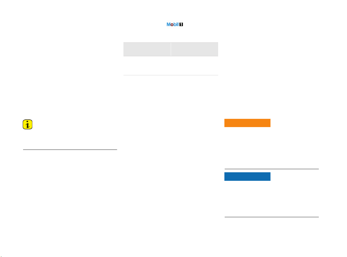
166 Maintenance and Car Care
Measuring the oil level after topping up
engine oil or opening the r
ear luggage
compartment lid
The oil level can be checked after waiting for
approx. 1 minute with the vehicle parked on a level
surface and the engine at operating temperature.
If the rear luggage compartment lid is opened
when the engine is cold (e.g. in order to top up
engine oil), the oil level cannot be displayed for
a certain time.
The message “No information about oil level
available at present” appears on the multi-
function display.
f Engine oil should therefore only be topped up
with the engine at operating temperature.
This ensures short waiting times for the
soonest possible oil level display.
Information
The “Check Engine” warning light may come on if
the cap of the oil filler opening is opened while the
engine is running.
Topping up Engine Oil
Porsche recommends .
The right oil for your vehicle:
1)
Generally, you can find details of the
manufacturer approvals on the oil containers or as
a notice displayed by the retailer.
The current approval status is also available from
your authorized Porsche dealer.
2)
SAE viscosity class – Example: SAE 0W-40
Specification 0W = Viscosity specification for
low temperatures (winter).
Specification 40 = Viscosity specification for
high temperatures.
3)
For all temperature ranges.
4)
For the temperature range above –13 °F
(–25 °C).
Always observe the following points:
– Use engine oils approved by Porsche only. This
is a precondition for optimum and problem-free
driving.
– Regular oil changes are part of servicing.
It is important that the service intervals,
particularly the oil change intervals, are
observed in accordance with the specifications
in the “Maintenance” booklet.
– Oils approved by Porsche can be mixed with
each other.
– Porsche engines are designed so that no oil
additives may be used.
– A label is located in the rear luggage
compartment, which provides you with
information on suitable oil for your engine.
Your authorized Porsche dealer will be pleased to
advise you.
Engine oil can ignite if it comes into contact with
hot engine parts.
f Top up engine oil only with the engine stopped
and ignition switched off.
f Please see the chapter “EXERCISE EXTREME
CAUTION WHEN WORKING ON YOUR VEHICLE”
on page 162.
Risk of damage through overflowing engine oil.
The luggage compartment or items of luggage
may become soiled in this event.
f Take care not to soil the luggage compartment
or items of luggage when checking and
topping up engine oil.
Complies with
approval
1)
Viscosity class
2)
Porsche A40 SAE 0W-40
3)
SAE 5W-40
4)
SAE 5W-50
4)
Burning engine oil
WARNING
h
NOTICE
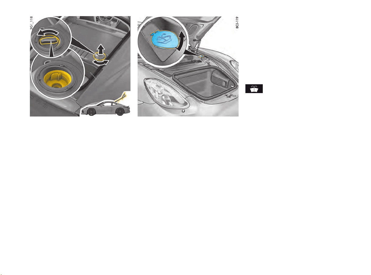
Maintenance and Car Care 167
1. Before opening the rear luggage compartment
lid, read off the oil level on the multi-function
display.
f Please see the chapter “DISPLAY AND
MEASUREMENT OF THE ENGINE OIL LEVEL”
on page 82.
2. Park the vehicle on a level surface.
3. Switch off engine (at operating temperature).
4. Open the rear lid.
5. Turn cap anti-clockwise and remove.
6. Unscrew cap on oil filler opening (illustration).
7. Top up engine oil according to the gauge on
the multi-function display.
8. Carefully close cap on the oil filler opening.
9. Fit cap and turn it clockwise.
10.Close the rear lid.
Washer Fluid
Observe the following points:
f Depending on the season, mix the water with
the appropriate additives (window cleaner
concentrate, antifreeze) in the correct mixture
ratio.
Summer filling with water + window cleaner
concentrate in the mixture ratio specified on
the container.
Winter filling with water + antifreeze +
window cleaner concentrate in the mixture
ratio specified on the container.
Always follow all the instructions on the
containers of the additives used.
f Only use window cleaner concentrate that
meets the following requirements:
– Dilutability 1:100,
– Phosphate-free,
– Suitable for plastic headlight lenses.
We recommend window cleaner concentrates
approved by Porsche. Your authorized Porsche
dealer will be pleased to advise you.
The washer fluid reservoir for windshield and
headlights is located in the front luggage
compartment (illustration).
A warning message appears on the multi-function
display if the washer fluid level is too low.
f Add washer fluid at the next opportunity.
The maximum filling capacity is approx.
1.59 US gallons (6 liters).
Adding washer fluid
1. Open cap on washer fluid reservoir
(illustration).
2. Add washer fluid.
3. Close cap carefully.
Warning message

168 Maintenance and Car Care
Wiper Blades
Maintenance notes
Risk of damage if wiper blades are not cleaned
properly. The graphite coating on the wiper blades
may be damaged.
f Do not clean the wiper blades using a cloth or
sponge, but rinse with clean water.
Risk of damage due to unintentional folding back
of wiper arm and frozen wiper blades.
f Always hold the wiper arm securely when
replacing the wiper blade.
f Thaw the wiper blades before lifting them from
the window.
Wiper blades that are in perfect condition are vital
for a clear view.
f Have the wiper blades replaced twice per year
(before and after the cold season) or if wiper
performance deteriorates or the blades are
damaged.
f After switching off the ignition, press the wiper
stalk down once 4.
The wipers move upwards by approx. 45°.
f Clean the windshield regularly with window
cleaner, especially after washing the vehicle in
a car wash.
We recommend Porsche window cleaner.
If they are very dirty (e.g. soiled with insect
remains), they can be cleaned with a sponge
or cloth.
If the wiper blades judder or squeak, this may be
due to the following:
– If the vehicle is washed in an automatic car
wash, wax residues may adhere to the
windshield. These wax residues can be
removed only by using window cleaner
concentrate.
– The wiper blades may be damaged or worn.
f Have damaged wiper blades replaced
immediately.
f Please see the chapter “WASHER FLUID”
on page 167.
Replacing wiper blades
f After switching off the ignition, press the wiper
stalk down once.
The wipers move upwards to an angle of
approx. 45°.
f Please read the separate instructions provided
by the wiper blade manufacturer.
f We recommend that you get your authorized
Porsche dealer to replace the wiper blades.
Risk of damage. If the wiper blades are not
changed properly, they can come loose when the
car is moving.
f Check that the wiper blades are seated
securely.
The wiper blades must engage properly in
the wiper arm.
Emission Control System
In the interest of clean air
Pollution of our environment has become a
problem that is of increasing concern to all of us.
We urge you to join us in our efforts for cleaner air
in controlling the pollutants emitted from the
automobile.
Porsche has developed an emission control
system that controls or reduces those parts of
emissions that can be harmful to our environment.
Your Porsche is equipped with such a system.
Porsche warrants the Emission Control System in
your new car under the terms and conditions set
forth in the Warranty Booklet.
You, as the owner of the vehicle, have the
responsibility to provide regular maintenance
service for the vehicle and to keep a record of all
maintenance work performed. To facilitate record
keeping, have services performed by authorized
Porsche dealers. They have Porsche trained
technicians and special tools to provide fast and
efficient service.
To assure efficient operation of the Emission
Control System:
f Have your vehicle maintained properly and in
accordance with the recommendations
described in your Maintenance Booklet. Lack
of proper maintenance, as well as improper
use of the vehicle, will impair the function of
the emission control system and could lead to
damage.
f Do not alter or remove any component of the
emission control system.
f Do not alter or remove any device, such as
heat shields, switches, ignition wires, valves,
etc., which are designed to protect your
vehicle's emission control system. In addition
NOTICE
NOTICE
NOTICE

Maintenance and Car Care 169
to serious engine damage, this can result in a
fire if excess raw fuel reaches the exhaust
system.
f Do not continue to operate your vehicle if you
detect engine misfire or other unusual
operating conditions.
Parking
The exhaust system becomes very hot when the
engine is running and remains hot for some time
after the vehicle is turned off. Flammable material
close to the exhaust system could ignite.
f Do not park or operate your vehicle in areas
where the hot exhaust system may come in
contact with dry grass, brush, fuel spill or
other flammable materials.
f If your car catches on fire for any reason, call
the fire department. Do not endanger your life
by attempting to put out the fire.
Undercoating
Additional undercoating or rust protection agents
on or near the exhaust system can become too
hot when driving and ignite, causing a fire.
f Do not apply additional undercoating or rust
protection agent on or near the exhaust
manifolds, exhaust pipes, catalytic converters
or heat shields. During driving the substance
used for undercoating could overheat and
ignite.
How Emission Control Works
When an automobile engine is running, it uses
energy generated through the combustion of a
mixture of air and fuel. Depending on whether a
car is driven fast or slowly or whether the engine
is cold or hot, some of the fuel (hydrocarbons)
may not be burned completely, but may be
discharged into the engine crankcase or exhaust
system. Additional hydrocarbons may enter the
atmosphere through evaporation of fuel from the
fuel tank. These hydrocarbons (HC), when
released into the air, contribute to undesirable
pollution.
In addition, carbon monoxide (CO) and oxides of
nitrogen (NOx) contribute to engine emissions.
They, too, are formed during the combustion
process and discharged into the exhaust system.
To reduce these pollutants, your Porsche is
equipped with a precisely calibrated fuel injection
system to assure a finely balanced air/fuel mixture
under all operating conditions.
Oxygen sensor
The oxygen sensor, installed in the exhaust pipe
continuously senses the oxygen content of the
exhaust and signals the information to an
electronic control unit. The control unit corrects
the air/fuel ratio, so the engine always receives an
accurately metered air/fuel mixture.
Crankcase ventilation
Through crankcase ventilation, undesirable
emissions from the engine crankcase are not
permitted to reach the outside atmosphere. These
emissions are recirculated from the crankcase to
the air intake system. From here the emissions
mix with the intake air and are later burned in the
engine.
Catalytic converters
The catalytic converters are efficient “clean-up”
devices built into the exhaust system of the
vehicle. The catalytic converters burn the
undesirable pollutants in the exhaust gas before it
is released into the atmosphere.
The exclusive use of unleaded fuel is
critically important for the life of the
catalytic converters. Therefore, only
unleaded fuel must be used.
The catalytic converters will be damaged by:
– Push or tow starting the vehicle,
– Misfiring of the engine,
– Turning off the ignition while the vehicle is
moving,
– Driving until the fuel tank is completely empty,
– By other unusual operating conditions.
f Do not continue to operate your vehicle under
these conditions, since raw fuel might reach
the catalytic converters. This could result in
Fire risk when parking
WARNING
h
Aftermarket
undercoating
WARNING
h

170 Maintenance and Car Care
overheating of the converters. Federal law
pr
ohibits use of leaded fuel in this car.
Fuel Economy
Fuel economy will vary depending on where,
when and how you drive, optional equipment
installed, and the general condition of your
car.
A car tuned to specifications and correctly
maintained, will help you to achieve optimal
fuel economy.
f Have your vehicle tuned to specifications. Air
cleaner should be dirt free to allow proper
engine “breathing”.
Battery should be fully charged.
Wheels should be properly aligned.
Tires should be inflated to the correct
pressure.
f Always monitor your fuel consumption.
f Drive smoothly, avoid abrupt changes in speed
as much as possible.
f Avoid jack rabbit starts and sudden stops.
f Do not drive longer than necessary in the lower
gears. Shifting into a higher gear early without
lugging the engine will help save fuel.
f Prolonged “warm up” idling wastes gas. Start
the vehicle just before you are ready to drive.
Accelerate slowly and smoothly.
f Switch off the engine if stationary for longer
periods.
f Any additional weight carried in the vehicle
reduces fuel economy. Always keep cargo to
a minimum and remove all unnecessary items.
f Organize your trips to take in several errands
in one trip.
f All electrical accessories contribute to
increased fuel consumption.
f Only switch on the air conditioning when
necessary.
The EPA estimated miles per gallon (mpg) is
to be used for comparison purposes, actual
mileage may be different from the estimated
mpg, depending on your driving speed,
weather conditions and trip length. Your
actual highway mileage may be less than the
estimated mpg.
f Please observe all local and national speed
limits.
Operating Your Porsche in other
Countries
Government regulations in the United States and
Canada require that automobiles meet specific
emission regulations and safety standards.
Therefore, cars built for the U.S. and Canada differ
from vehicles sold in other countries.
If you plan to take your Porsche outside the
continental limits of the United States or Canada,
there is the possibility that:
– Unleaded fuel may not be available,
– Unleaded fuel may have a considerably lower
octane rating. Excessive engine knock and
serious damage to both engine and catalytic
converters could result,
– Service may be inadequate due to lack of
proper service facilities, tools or diagnostic
equipment,
– Replacement parts may not be available or
very difficult to get.
Porsche cannot be responsible for the
mechanical damage that could result
because of inadequate fuel, service or parts
availability.
If you purchased your Porsche abroad and want to
bring it back home, be sure to find out about
shipping and forwarding requirements, as well as
current import and customs regulations.
Maintenance and Car Care 171
Fuel
When the ignition is on, the fuel level is displayed
on the instrument panel.
f Please see the chapter “J – FUEL GAUGE”
on page 76.
f Fire, open flame and smoking are prohibited
when handling fuel.
Fuel and fuel vapors are hazardous to health.
f Avoid contact with skin or clothing, since injury
to your skin may occur.
f Do not inhale fuel vapors, since they may make
you ill and possibly cause death if inhalation is
prolonged and occurs in a closed space.
To prevent damage to the emission control
system and engine:
f Never drive the tank dry.
f Avoid high cornering speeds after the warning
lights have come on.
f Please see the chapter “FUEL ECONOMY”
on page 170.
Check engine warning light
If the warning lights in the instrument panel come
on and remain on while driving, it suggests:
– a potential engine control problem and the
need for system service or
– an improperly fastened tank cap or
refueling with engine running.
Information
It is important that the service intervals,
particularly the oil change intervals, are observed
in accordance with the specifications in the
“Maintenance” booklet.
Refueling
The RF energy from a cellphone can cause a
sparking on bare metal, much like aluminum foil in
a microwave oven. The spark could ignite gasoline
fumes present while refeuling.
f Do not use a cellphone while pumping gas.
Static discharge from your body can ignite
gasoline fumes present when you get back out of
the vehicle and touch the fuel nozzle.
f Do not re-enter the vehicle while pumping gas.
1. Stop the engine and switch off the ignition.
2. Open the filler flap by pressing on the rear part
of the filler flap (arrow).
The vehicle must be unlocked.
Refueling fire risk
Fuel vapors and skin
contact
DANGER
h
WARNING
h
NOTICE
Refueling fires /
cellphones
Refueling fires / static
electricity
DANGER
h
DANGER
h
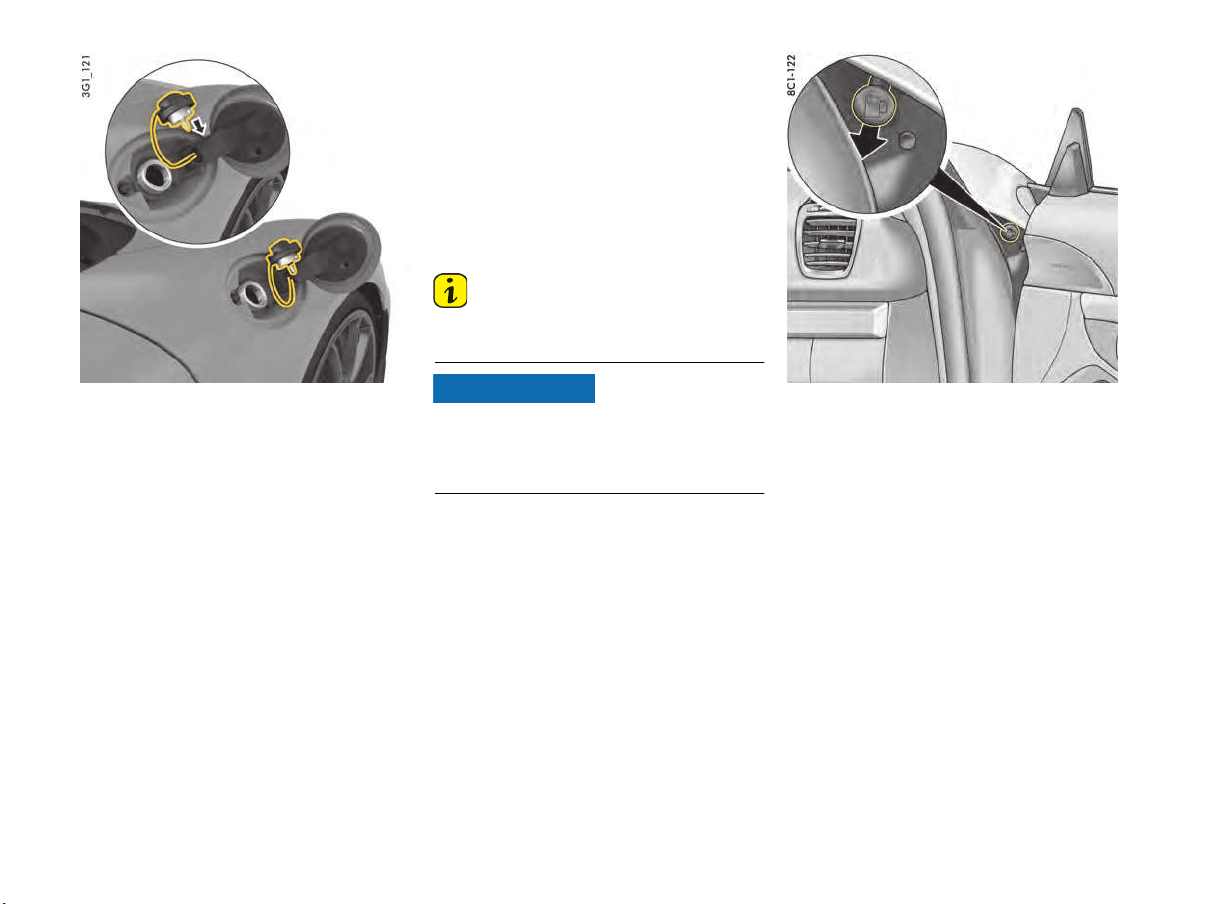
172 Maintenance and Car Care
3. Slowly open and r
emove the tank cap.
Put the tank cap into the holder (arrow).
4. Insert the pump nozzle fully into the filler neck.
The handle of the pump nozzle must point
downwards.
The maximum filling capacity is approx.
14.27 US gallons (54 litres) (optionally
approx. 16.91 US gallons (64 litres)), with a
reserve of approx. 2.64 US gallons (10 litres).
5. Operate the pump nozzle and refuel the
vehicle.
Do not add further fuel once the correctly
operated automatic pump nozzle has switched
off. Fuel could spray back or could flow over
when heated.
6. Replace the tank cap immediately after
refueling and close it until you hear and feel it
locking.
7. Close the filler flap and press on the rear of the
filler flap until it engages securely.
Information
If you lose the tank filler cap, you must replace it
only with an original part.
Risk of damage to decorative foils.
Decorative foils may fade if they come into
contact with fuel.
f Wipe off any spilled fuel immediately.
Emergency unlocking of the filler flap
If the electrical release mechanism is faulty, the
filler flap can be opened as follows:
f Open the passenger’s door.
f Pull the button in the right-hand door aperture
(arrow).
The filler flap pops open.
NOTICE

Maintenance and Car Care 173
Portable Fuel Container
If the portable fuel container is damaged in an
accident and fuel escapes, it could ignite or
explode.
f Do not carry a portable fuel container on
journeys.
f Observe the relevant laws which prohibit fuel
transport.
Vapors from the fuel are hazardous to health.
f Do not carry a portable fuel container in the
occupant compartment.
Fuel Recommendations
Your Porsche is equipped with catalytic
converters and must use UNLEADED FUEL
WITHOUT METALLIC ADDITIVES ONLY.
Your engine is designed to provide optimum
performance and fuel economy using unleaded
premium fuel with an octane rating of 98 RON/
88 MON (93
CLC or AKI)
. Porsche therefore
recommends the use of these fuels in your
vehicle.
Porsche also recognizes that these fuels may not
always be available. Be assured that your vehicle
will operate properly on unleaded premium fuels
with octane numbers of at least
95 RON/
85 MON
(90 CLC or AKI)
, since the engine’s
“Electronic Octane™ knock control” will adapt the
ignition timing, if necessary.
If fuels of less than
95 RON/
85 MON
(90 CLC
or AKI)
are used however, this could reduce
performance and increase fuel consumption.
f Avoid driving at full throttle.
It is important to observe the regular service
intervals, and particularly the oil change intervals,
specified in the “Maintenance” booklet.
The use of UNLEADED FUEL WITHOUT
METALLIC ADDITIVES ONLY is critically
important to the life of the catalytic
converters. Deposits from leaded fuels or
metallic additives will ruin the converters and
make them ineffective as an emission
control device. Metallic additives can cause
serious engine damage.
Cars with catalytic converters have a smaller fuel
tank opening, and gas station pumps that
dispense unleaded fuel have smaller nozzles. This
will prevent accidental pumping of leaded fuel into
cars with catalytic converters.
Unleaded fuels may not be available outside the
continental U.S. and Canada. Therefore, we
recommend you do not take your car to areas or
countries where unleaded fuel may not be
available.
Information
In some countries the available fuel quality may
not meet the requirements of your Porsche vehicle
and can result in coking inside or around the
injectorbores or other serious damage to the
engine, fuel system or exhaust system.
In this case, the fuel may be mixed only with the
additive sold and recommended by Porsche after
consulting your authorized Porsche dealer.
Porsche part number 000 043 206 89.
f Observe the instructions and mixture ratios
stated on the container.
It is important that the service intervals,
particularly the oil change intervals, are observed
in accordance with the specifications in the
“Maintenance” booklet.
Risk of destruction of the engine, fuel system or
exhaust system if non-approved additives are
used.
f Use only additives approved by Porsche.
The use of other additives can result in
destruction of the engine, fuel system or
exhaust system of your vehicle.
Octane ratings
Octane rating indicates a fuel’s ability to resist
detonation. Therefore, buying the correct octane
gas is important to prevent engine “damage”.
The RON octane rating is based on the research
method. The CLC (U.S. Cost of Living Council
octane rating) or AKI (antiknock index) octane
rating usually displayed on U.S. fuel pumps is
calculated as research octane number plus motor
octane number, divided by 2, that is written as:
The CLC or AKI octane rating is usually lower than
the RON rating:
For example: 95 RON equals 90 CLC or AKI.
Fuels containing ethanol
Do not use any fuels containing more than
15 percent ethanol by volume.
We recommend, however, to change to a different
fuel or station if any of the following problems
occur with your vehicle:
– Deterioration of driveability and performance.
– Substantially reduced fuel economy.
Transporting filled fuel
containers
Portable fuel container
vapor hazard
DANGER
h
WARNING
h
NOTICE
RON+MON
2
R+M
2
or

174 Maintenance and Car Care
– Vapor lock and non-start problems, especially
at high altitude or at high temperatur
e.
– Engine malfunction or stalling.
Fuel Evaporation Control
Fuel tank venting
The evaporation chamber and the carbon canister
prevent fuel vapors from escaping to the
atmosphere at extreme high outside
temperatures, when driving abruptly around
curves and when the car is parked at an incline or
in any other nonlevel position.
Vapor control system and storage
When the fuel tank is filled, vapors are collected in
the evaporation chamber by a vent line leading the
vapors to the carbon canister where they are
stored as long as the engine does not run.
Purge system
When the engine is running, the fuel vapors from
the canister will be mixed with fresh air from the
ambient air of the canister. This mixture will be
directed to the intake air housing by the tank vent
line, mixed with the intake air and burned during
normal combustion.
Car Care Instructions
f Please see the chapter “MEASUREMENTS ON
TEST STANDS” on page 164.
Regular Maintenance and correct care helps
to maintain the value of your car and is also
a requirement for maintaining the
manufacturers vehicle warranties.
Your authorized Porsche dealer has specially
developed car-care products from the
Porsche program available either singly or
as complete car-care sets. They will be
pleased to help you select suitable products.
Whether you use Porsche products or other
commercially available cleaning agents first
make sure of their correct application.
A Porsche that is well-cared for can look like new
for years. It all depends on the amount of care the
owner is willing to give the car.
Cleaning agents may be hazardous to your health.
Most chemical cleaners are concentrates which
require dilution. High concentrations might cause
problems ranging from irritation to serious injury.
f Keep cleaning agents out of reach from
children.
f Observe all caution labels.
f Always read directions on the container before
using any product. These directions may
contain information necessary to avoid
personal injury.
f Do not use fuel, kerosene, naphtha, nail polish
remover or other volatile cleaning fluids. They
may be toxic, flammable or hazardous in other
ways. Only use spot removing fluids in a well
vented area.
f Do not clean the underside of chassis,
fenders, wheel covers, etc., without protecting
your hands and arms as you may cut yourself
on sharp-edged metal parts.
Risk of damage to the vehicle or property from
cleaning agents.
f Observe all caution labels.
Information
Moisture and road salt on brakes may affect
braking efficiency.
f Test the brakes after each vehicle washing.
Chemical cleaners
WARNING
h
NOTICE

Maintenance and Car Care 175
High-pressure cleaning equipment, steam
cleaners
Risk of damage as a result of using high-pressure
cleaning equipment, steam cleaners or similar.
High-pressure cleaning equipment, steam
cleaners or similar can damage the following
components:
– Tires
– Logos, emblems
– Painted surfaces
– Alternator
– Electrical components and plug connections in
the engine compartment
f Always read the operating instructions
provided by the equipment manufacturer.
f Always cover the lid of the brake fluid reservoir
prior to cleaning. Never point the cleaning jet
directly at the lid.
f When cleaning with a flat-jet nozzle or
a so-called “dirt blaster”, maintain a minimum
distance of 20 in. (50 cm).
f Never use high-pressure cleaning equipment
or steam cleaners with a round-jet nozzle.
A high-pressure cleaning device or steam
cleaner fitted with a round nozzle will damage
your vehicle. The tires are particularly
susceptible to damage.
f Do not point the cleaning jet directly at any of
the aforementioned components.
Decorative film
Risk of damage due to separation of the
decorative film when using high-pressure cleaning
equipment, steam cleaners or similar cleaning
equipment.
f Do not use high-pressure cleaning equipment,
steam cleaners, etc. to clean decorative films.
Care of door lock
f Never use excessive force.
f If the lock is frozen, use an ordinary de-icer.
Car washing
The best protection for the vehicle from the
damaging effects of the environment is frequent
washing and preservation.
The longer road salt, road dust, industrial dust,
insect remains, bird excrement, and tree
exudations (e.g. resin, pollen), etc. are allowed
to remain on the bodywork, the more harmful
their effect.
Observe the following points in order to ensure
that the vehicle is washed thoroughly without
damaging the paintwork:
f The underside of the vehicle should also be
thoroughly washed at the end of the gritting
season at the latest.
f Wash your vehicle only at sites provided for
this purpose to prevent soot, grease, oil and
heavy metals from entering the environment.
f New cars should be washed carefully with
plenty of clear water to protect the new paint
work. Dark paint finishes show up the smallest
of surface damage (e.g., scratches) more
readily than lighter colors.
Dark colors are slightly more susceptible to
scratching and require particularly careful
paint care.
Dark paints make even the smallest surface
blemishes (scratches) more conspicuous than
lighter colors.
f Do not wash your Porsche in direct sunlight or
when its body is hot.
f When washing by hand, use a car shampoo,
plenty of water, and a soft sponge or
washing brush.
We recommend Porsche car shampoo.
f Start washing the vehicle by thoroughly
wetting the paintwork and rinsing the heavy
dirt off.
f After washing the vehicle, rinse it thoroughly
with water and rub it dry with chamois-leather.
Do not use the same chamois for rubbing dry
as you use for cleaning the windshield and
windows.
NOTICE
NOTICE

176 Maintenance and Car Care
Reduced or uneven braking action may be caused
by wet brakes.
f After washing the vehicle, test the brakes and
steering and briefly brake the disks dry.
When doing so, make sure that vehicles
traveling behind you are not affected.
Cleaning in car washes
Optional add-on parts or parts that project beyond
the contours of the vehicle may be damaged by
design features of car washes.
The following parts are particularly at risk:
– Windshield wipers and rear wiper (always
switch them off – wiper stalk in position 0 –
to prevent them wiping unintentionally in
sensor operation).
– Exterior mirrors (always fold in).
– External antenna (always unscrew).
– Spoiler.
– Wheels (the wider the rim and the lower the tire
height, the greater the risk of damage).
– High-gloss wheels (to prevent these from
getting scratched, do not clean with the wheel-
cleaning brushes of the car wash).
f Please consult the operator before using
automatic car washes.
f All parts not reached by a car wash, such as
door and lid seams or door sills, must be
washed and polished by hand.
Information
Automatic car washes spray water at odd angles
and high pressures, which are not seen in normal
driving. Therefore, water can sometimes find its
way into the passengers compartment during or
shortly after the car wash.
Paint care
In order to protect the paint on your vehicle in the
best possible way against mechanical and
chemical damage, you should
– preserve it regularly,
– polish it if necessary,
– remove spots and stains, and
– repair damaged paintwork.
f Do not apply care products containing silicone
to the windows.
Information
f Never rub a dusty vehicle with a dry cloth,
because the grains of dirt will damage the
paintwork.
f Do not treat matt-painted components with
preservatives or polishes as these remove the
matt effect.
Preservation
The paint surface becomes dull over time due to
weathering.
f Preserve paint regularly.
f Apply paint preservative after washing the
vehicle and polish it smooth to preserve the
paintwork.
This keeps the paint shiny and elastic. Dirt is
prevented from adhering to the paint surface and
industrial dust is prevented from penetrating the
paint.
Polishing
Only when the original shine can no longer be
obtained using preservatives should paint polish
be used to clean the paint.
We recommend Porsche paint polish.
Removing spots and stains
f Remove tar spatters, traces of oil, insects etc.
as soon as possible using an insect remover,
as they discolor the paint if left to work on it
over time.
f Wash the treated areas carefully afterwards.
Repairing minor paint damage
f Have minor paint damage (cracks, scratches
or stone damage) repaired immediately
before corrosion begins.
Please contact an authorized Porsche dealer.
If traces of corrosion have already formed, these
must be thoroughly removed. An anti-corrosion
primer must then be applied to these spots,
followed by top-coat paint.
Paint data can be found on the vehicle data
carrier.
f Please see the chapter “VEHICLE
IDENTIFICATION NUMBER” on page 218.
Wet brakes
WARNING
h

Maintenance and Car Care 177
Cleaning windows
f Clean all windows regularly, inside and out,
with window cleaner.
We recommend Porsche window cleaner.
f Do not use the same chamois for painted
surfaces and for drying the windows.
Preservative residues could reduce
transparency.
f Remove insect residues with insect remover.
Information
The door windows have a water-repellent
(hydrophobic) coating, which prevents soiling of
the windows.
This coating is subject to natural wear and can be
renewed.
f Please contact an authorized Porsche dealer.
Care of windshield wiper blades
Windshield wiper blades that are in perfect
condition are vital for a clear view.
f Please see the chapter “WIPER BLADES”
on page 168.
Repairing the underbody protection
The underside of your car is durably protected
against chemical and mechanical influences.
As it is not possible to exclude the risk of damage
to this protective coating in day to day driving, it
is advisable to have the underside of the car
inspected at certain intervals - preferably before
the start of winter and again in spring - and the
undercoating restored as necessary.
Your authorized Porsche dealer is familiar with the
bodyseal treatment procedures and has the
necessary equipment for applying factory
approved materials. We recommend that you
entrust them with such work and inspections.
Unlike conventional spray oils, undercoating and
rust-proofing compounds based on bitumen or
wax do not attack the sound-proofing materials
applied at the factory.
The exhaust system becomes very hot when the
engine is running. Flammable material close to the
exhaust system could ignite. Additional
undercoating or rust protection agents on or near
the exhaust system can become too hot when
driving and ignite.
f Do not apply additional undercoating or rust-
proofing on or near the exhaust manifold,
exhaust pipes, catalytic converters or heat
shields. During driving the substance used for
undercoating could overheat and ignite.
f Before applying fresh underseal, carefully
remove deposits or dirt and grease. Once it
has dried, the new undercoating compound
forms a tough protective coating which
provides efficient rust-proofing of the floor
panels and components.
f Always apply a fresh coating of suitable
preservative to unprotect areas after cleaning
the underside of the body, the transmission,
the engine or carrying out repairs to under-
body, engine or transmission components.
Effective rust-proofing is particularly important
during the cold weather season. If your car is
driven frequently in areas where salt has been
spread on the roads, the whole engine
compartment should be cleaned thoroughly after
the winter to prevent salt from causing any lasting
damage. A full underbody wash should also be
performed at the same time.
Exhaust system fire risk
WARNING
h

178 Maintenance and Car Care
Cleaning headlights, lights, interior and
exterior plastic components, adhesive
foils
Observe the following points:
f Use only clean water and a little dishwashing
liquid or interior window cleaner to clean
headlights, lights, plastic components and
surfaces.
Use a soft sponge or a soft, lint-free cloth.
Information
An interior window cleaner can also be used to
clean plastic surfaces (always read the cleaning
instructions on the container).
We recommend Porsche interior window cleaner.
f Gently wipe the surface without applying too
much pressure.
f Do not clean when dry.
f Never use other chemical cleaners or
solvents.
f Rinse cleaned surfaces with clear water.
Alloy wheels
Metal particles (e.g. brass or copper in brake
dust) must not remain too long on alloy wheels.
Contact corrosion can cause pitting.
Information
Cleaners with an oxide-removing effect or wrong
pH value, as are commonly used for other metals,
as well as mechanical tools and products, will
damage the oxide layer and are therefore
unsuitable.
f Use only cleaners for alloy wheels
(pH value 9.5). Products with the wrong
pH value can destroy the protective layer
on the wheels.
We recommend Porsche cleaner for alloy rims.
f If possible, wash the wheels every two weeks
with a sponge or washing brush. If the wheels
are exposed to road salt, grit or industrial dust,
weekly cleaning is necessary.
f Every three months, after cleaning, grease the
wheels with car wax or an acid-free grease
(e.g. Vaseline).
Rub the grease in well with a soft cloth.
f Please see the chapter “CLEANING IN CAR
WASHES” on page 176.
If cleaning agents (e.g. wheel cleaning agents)
come into contact with the brake disks, the
resulting film on the brake disks can impair
braking performance.
f Make sure that no cleaning agent comes into
contact with the brake disks.
f If cleaning agent has come into contact with
the brake disks, clean the brake disks
thoroughly with a strong jet of water.
f Paying attention to any road users behind you,
dry the brake disks by applying the brakes.
Stainless steel tailpipes
Stainless steel tailpipes can discolor due to
soiling, strong heat and combustion residues.
The original shine can be achieved again using
commercially available metal lustre paste or
metal polish.
Cleaning door, roof, lid and window seals
The lubricant coating on the inner door seals may
be damaged by unsuitable cleaning and care
agents.
f Do not use any chemical cleaning agents or
solvents.
f Do not use any preservative agents.
f Wash dirt (e.g. abrasion, dust, road salts) from
all seals regularly using warm soapy water.
f If there is a risk of frost, protect the outer door
seals and the lid and flap seals against freezing
into place with a suitable care product.
Cleaning agents on
brake disks
WARNING
h
NOTICE

Maintenance and Car Care 179
Leather care
The natural surface markings of leather,
e.g. creases, healed scars, insect sting marks,
structural differences and slight variations in
shade and grain add to the attractiveness of the
high-quality natural leather product.
Observe the following care instructions:
The leather will be damaged by the use of
unsuitable cleaning and care agents and by
inappropriate treatment.
f Do not use caustic cleaners or hard cleaning
objects!
f Make sure that perforated leather does not get
wet on its reverse side.
f Remove water drops from the leather without
delay.
f Clean all types of leather regularly to remove
fine dust using a soft, damp, white woollen
cloth or a commercially available microfibre
cloth.
f Remove heavy contamination (not water or
moisture stains) with a leather cleaner.
Always read the instructions for use given on
the containers.
We recommend Porsche leather care liquid.
f Treat cleaned leather only with a leather care
product.
We recommend Porsche leather care liquid.
Seats with seat ventilation
Care instructions for water or moisture
stains.
Rain water or moisture can stain the perforated
leather.
Removing water and moisture stains
Preconditions:
– Seat heating and seat ventilation must be
switched off.
– No direct sunlight.
– Do not use leather cleaners or care products
to remove water and moisture stains.
f Blot the entire seat or backrest surface using
a clean, absorbent sponge and distilled water.
Make sure that the perforated leather does not
get wet on its reverse side.
f Allow the seat covering to dry completely at
room temperature out of direct sunlight.
Do not dry the seat covering by switching on
the seat heating and seat ventilation.
f Once dry, wipe the seat covering with a dry,
lint-free cloth.
Cleaning carpet, floor mats
f Use a vacuum cleaner or a brush (not too soft)
for cleaning.
f Heavy dirt and stains can be removed with
a stain remover.
We recommend Porsche stain remover.
To protect carpets, the Porsche range of
accessories includes mats of the correct size and
with the appropriate fastening.
Improperly secured floor mats can obstruct pedal
travel.
f Always check the movement of the pedals
before driving and make sure that they are not
obstructed by a floor mat or any other object.
f Secure the floor mat to prevent it from sliding
into positions that could interfere with the safe
operation of your vehicle – do not lay them
loosely in the vehicle.
Your authorized Porsche dealer will be glad to
offer you floor mats of correct size including a
securing possibility.
Cleaning airbag covers
Incorrect modifications may damage the airbag
system. The airbag may not deploy properly in the
event of an accident.
f Do not make any modifications whatsoever to
individual components, such as the padded
covers on the steering wheel, the instrument
panel, the underside of the instrument panel,
front seats and door panels.
f Have your authorized Porsche dealer to clean
these components.
NOTICE
Obstructed pedals
Vehicle interior
modifications
WARNING
h
DANGER
h

180 Maintenance and Car Care
Cleaning fabric linings
f Fabric linings on pillars, roofliner and sun
blinds, etc. must be cleaned only using
suitable cleaning agents or a suitable dry foam
and a soft brush.
Alcantara
®
care
Do not use leather care products to clean
Alcantara
®
. Alcantara
®
is a manufactured
product. It is not genuine leather or suede.
For regular care, it is sufficient to clean the cover
with a soft brush.
Strong abrasion or rubbing when cleaning will
produce a lasting change to the surface.
Cleaning when lightly soiled
f Wet a soft cloth with water or a neutral soap
solution and wipe off the dirt.
Cleaning when heavily soiled
f Wet a soft cloth with lukewarm water or
thinned white spirit and dab the dirt from the
outside in.
Cleaning the safety belts
f Use mild detergent to clean soiled belts.
f When drying, avoid direct sunlight.
f Only use suitable cleaning agents.
f Do not tint or bleach the belts.
The belt fabric could be weakened, thus
affecting safety.
Storing your Porsche
If you intend to store your Porsche for a prolonged
period, please consult your authorized Porsche
dealer. The staff will be glad to advise you on the
most suitable and necessary methods.
f Clean your vehicle thoroughly inside and
outside.
The under carriage and chassis components
should be free of dirt and salt deposits.
f Fill up the fuel tank.
f Change the oil and oil filter, and run the engine
for several minutes.
f Increase the tire pressure to 50 psi/3.5 bar/
350 kPa.
It is not recommended to lift the vehicle, due to
the possibility of corrosion on shock absorber
piston shafts.
The vehicle should be moved slightly,
approximately every four weeks, to prevent flat
spot on the tires.
Climate control
The air conditioning system should be in good
working condition and fully charged.
Windshield/Headlight washer
f Check and correct antifreeze/cleaning solution
level as necessary.
Electrical system
f Remove the battery from the vehicle and store
it in a cool dry place, not on a cement floor.
When the battery is disconnected, the
alarm system is deactivated.
f Recharge the battery every 3 months. If the
battery remains in the vehicle with the cables
connected, it is necessary to check, remove
and recharge the battery every 2-3 weeks.
Do not fast charge the battery.
f Please see the chapter “BATTERY (12 VOLT)”
on page 205.
Vehicle interior
The interior must be dry, especially in the area of
the floor carpets. The use of drying agents (Silica-
Gel) is recommended in vehicles with leather
interior and in areas with high humidity. The
recommended amount is 3 fabric bags of 1.1 lbs.
(500 grams) each placed on the floor carpets.
Windows, doors and lids must be closed. The air
vents should be opened.

Minor Repairs 181
Minor Repairs
Exercise Extreme Caution when Working
on your vehicle ...........................................182
Checking the Coolant Level and
Adding Coolant ...........................................184
Brake Fluid .................................................185
Electromechanical Power Steering ...............186
Changing Air Cleaner...................................186
Changing Particle Filters ..............................186
Tires and Wheels ........................................186
Changing Wheels ........................................196
Wheel Attachment Faces .............................198
Wheel Bolts ...............................................199
Flat Tire......................................................199
Electrical System ........................................201
Battery (12 volt)..........................................205
External Power Supply, Emergency
starting with jumper cables ..........................207
Changing Car Key (Remote Control) Battery ..209
Replacing bulbs ..........................................210
Headlights ..................................................210
Headlight Adjustment...................................213
Towing .......................................................214
Fire extinguisher .........................................216

182 Minor Repairs
Exercise Extreme Caution when
Working on your vehicle
The engine compartment of any motor vehicle is a
potentially hazardous area. If you are not fully
familiar with proper repair procedures, do not
attempt the adjustments described on the
following pages.
This caution applies to the entire vehicle.
Many vehicle fluids are highly flammable, e. g.
fuel, engine and transmission oil. Fuel vapors can
cause an explosion. When a battery is being
charged, highly explosive gases can develop.
f Do not smoke or allow an open flame around
the battery or fuel.
Pay attention to sparks, e. g. when coming into
contact with cables.
Keep a fire extinguisher close at hand.
f Ensure that there are no open flames in the
area of your vehicle at any time when fuel
fumes might be present. Be especially
cautious of devices such as hot water heaters
which ignite a flame intermittently.
f Only work on your vehicle outdoors or in a well
ventilated area.
Refill fluids, e. g. engine oil, brake fluid or coolant
are hazardous to health (poisonous, irritant,
caustic).
f Keep these fluids out of children's reach and
dispose of them in accordance with the
appropriate regulations.
f Only work on your vehicle outdoors or in a well
ventilated area.
Engine exhaust is dangerous if inhaled.
Engine exhaust fumes have many components
which you can smell. They also contain carbon
monoxide (CO), which is a colorless and odorless
gas.
Carbon monoxide can cause unconsciousness
and even death if inhaled.
f Only work on your vehicle outdoors or in a well
ventilated area.
The engine and surroundings components, the
exhaust system and coolant become very hot
when the engine is running.
The coolant reservoir is pressurized. Careless
opening of the coolant reservoir can lead to hot
coolant suddenly spraying out.
f Take care when working near hot parts of the
vehicle, in particular engine parts and parts of
the exhaust system.
f Before working in the engine compartment,
always switch the engine off and let it cool
sufficiently.
f Allow the engine to cool down before opening
the cap of the coolant reservoir and protect
your hands, arms and face from any possible
escape of hot coolant.
Take great care to ensure that hands, fingers,
articles of clothing (e. g. ties, sleeves, etc.),
necklaces or long hair cannot be caught up by the
radiator fans, drive belt or other moving parts.
The radiator fans in the front of the vehicle may be
operating or unexpectedly start operating when
the engine is switched on.
f Exercise extreme care that parts of the body,
articles of clothing or jewelry do not get caught
in the radiator fan, drive belt or other moving
parts.
f Carry out work in these areas only with the
engine off and exercise extreme caution.
When the ignition is on, all cables and wires of the
ignition system carry a high voltage.
f Exercise special care when working on the
ignition system.
Fire and explosion
hazar
ds
DANGER
h
Fluid health hazards
Exhaust gas inhalation
Hot engine parts,
exhaust system and
fluids
WARNING
h
WARNING
h
WARNING
h
Moving engine parts
Electric shock from
ignition system
WARNING
h
WARNING
h

Minor Repairs 183
If the vehicle is not secured, or incorrectly
secured, during repair work, it could move
unexpectedly or fall from the car jack or car lift.
f Be alert and cautious around the engine at all
times while it is running.
If you have to work on the engine while it is
running, always apply the electric parking
brake.
f Always support your car with safety stands if it
is necessary to work under the car. The jack
supplied with the car is not adequate for this
purpose.
Switch off level control of air suspension and
height adjustment.
Please see the chapter “RAISING THE VEHICLE
WITH A LIFTING PLATFORM, TROLLEY JACK
OR STANDARD JACK” on page 195.
f Jack up the vehicle only at the specified
jacking points on the underside of the vehicle.
f Never start the engine when the vehicle is
jacked or lifted up. Vibration from the engine
could cause the vehicle to fall.
f When working under the car without safety
stands but with the wheels on the ground,
make sure the car is on level ground, the
wheels are blocked, and that the engine
cannot be started. Withdraw ignition keys.
Information
f Incomplete or improper servicing may cause
problems in the operation of the car. If in doubt
about any servicing, have it done by your
authorized Porsche dealer.
Improper maintenance during the warranty
period may affect your Porsche warranty
coverage.
f Some countries require additional tools and
special spare parts to be carried in your
vehicle. Please make enquiries before driving
abroad.
T
The engine-compartment blowers are mounted in
the engine compartment.
After the engine is switched off, the engine
compartment temperature is monitored for
approx. 30 minutes.
During this period, and depending on
temperature, the engine-compartment blowers
may continue to run or start to run.
f Carry out work in this area only with the engine
off and exercise extreme caution.
The radiators and radiator fans are in the front of
the vehicle.
The radiator fans in the front of the vehicle may be
operating or unexpectedly start operating when
the engine is switched on.
f Carry out work in these areas only with the
engine switched off.
f Take great care to ensure that parts of the
body, items of clothing or jewellery cannot be
drawn in by the radiator fan, engine-
compartment blower, drive belt or other
moving parts.
Measurements on test stands
Performance test
Performance tests on roller-type test stands are
not approved by Porsche.
Brake tests
Brake tests must be performed only on roller-type
test stands.
The following limit values must not be exceeded
on roller-type test stands:
– Test speed 4.7 mph (7.5 km/h)
– Test duration 20 seconds
Testing the electric parking brake
Electric parking brake tests on the brake test
stand must only be performed with the ignition
switched on and with the manual gearshift lever in
neutral or the Porsche Doppelkupplung selector
lever in position N.
The vehicle switches automatically to brake test
stand mode, in which the electric parking brake
can be tested.
The message “Electric parking brake in
service mode” appears on the multi-function
display in the instrument panel.
Balancing wheels on the vehicle
During finish balancing of the wheels, the entire
vehicle must be lifted and the wheels must be free
to turn.
Information
The tools required for changing a wheel (e.g. jack,
wheel bolt wrench, assembly aids) are not
supplied as standard with the vehicle. Your
authorized Porsche dealer will be pleased to
advise you.
Failure to secure vehicle
WARNING
h
Radiator fans, engine
compartment blowers
WARNING
h
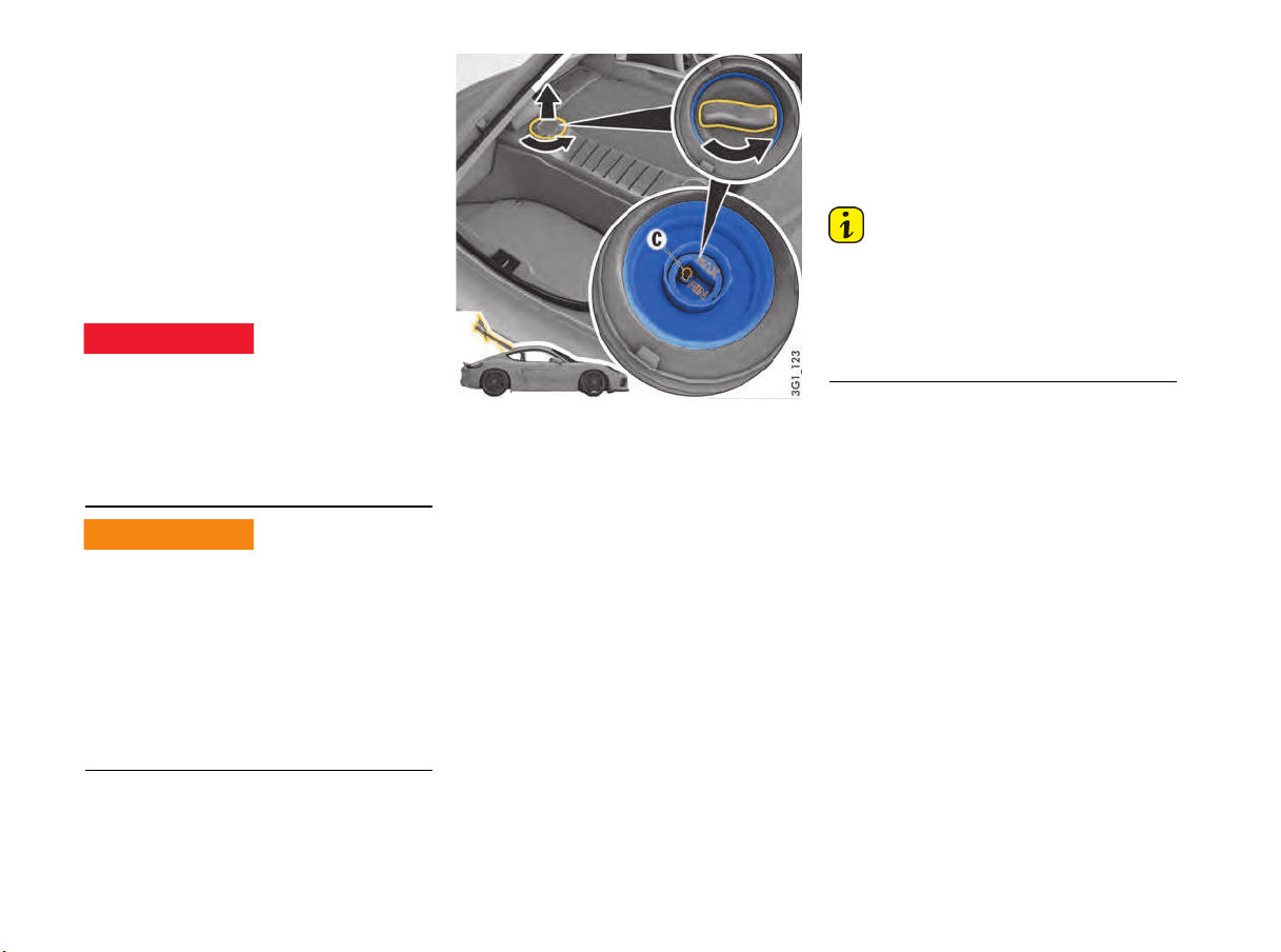
184 Minor Repairs
Checking the Coolant Level and
Adding Coolant
The coolant provides year-round protection from
corrosion and freezing down to –35 °F (–37 °C).
Regular checking of the coolant level is part of
servicing. The coolant level only needs to be
checked when a warning message appears on the
multi-function display in the instrument panel.
f Please see the chapter “OVERVIEW OF
WARNING AND INFORMATION MESSAGES”
on page 109.
f Use only antifreeze authorized by Porsche.
Coolant is hazardous to health. Coolant can be
deadly to children or pets if consumed.
f Keep coolant out of children's reach.
f Also, keep coolant away from your pets. They
can be attracted to it should there be a spill, or
to used coolant left in an open container.
The coolant becomes very hot when the engine is
running and can burn you.
The coolant reservoir is pressurized. Careless
opening of the coolant reservoir can lead to hot
coolant suddenly spraying out.
f Do not open the cap on the reservoir when the
engine is hot.
f Allow the engine to cool down before opening
the cap and protect your hands, arms and face
from any possible escape of hot coolant.
C - Coolant level indicator
Checking the coolant level when a warning
message appears on the multi-function display in
the instrument panel:
1. Allow the engine to cool as far as possible.
2. Turn cap anti-clockwise and remove.
3. Cover the reservoir cap with a cloth.
Open reservoir cap carefully and allow any
overpressure to escape.
Finally, unscrew reservoir cap completely.
4. Reading off the engine coolant level:
When the engine is cold and the vehicle is
level, the coolant level indicator C must be
between MIN and MAX markings.
5. Top up with coolant if necessary.
Only add a mixture of antifreeze and distilled
water in equal parts.
Antifreeze in coolant:
50 % provides antifreeze protection down
to –35 °F (–37 °C).
The maximum fill level is reached when the
coolant level indicator C is at the MAX marking.
Do not exceed the MAX-mark when topping up.
6. Screw the cap on the reservoir closed until it
locks securely.
7. Fit cap and turn it clockwise.
8. Have the cooling system checked.
Please contact an authorized Porsche dealer.
Information
If pure water is added in an emergency, the mixing
ratio will have to be corrected.
A significant loss of coolant indicates a leak in the
cooling system.
f The cause must be eliminated without delay.
Please contact an authorized Porsche dealer.
Swallowing engine
coolant
Hot engine coolant
DANGER
h
WARNING
h
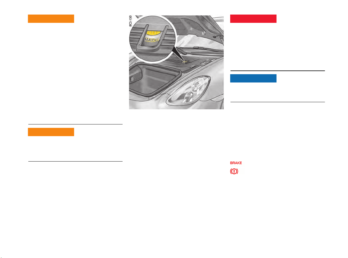
Minor Repairs 185
Hands, fingers, items of clothing (ties, sleeves,
etc.), necklaces or long hair can be drawn in by
moving parts, e.g. the engine-compartment
blowers, drive belt, etc., when working in the
engine compartment.
The engine-compartment blowers are mounted in
the engine compartment.
After the engine is switched off, the engine
compartment temperature is monitored for
approx. 30 minutes.
During this period, and depending on
temperature, the engine-compartment blowers
may continue to run or start to run.
f Carry out work in this area only with the engine
off and exercise extreme caution.
The engine and adjacent components become
very hot when the engine is running.
f Exercise extreme caution when working in the
engine compartment.
Brake Fluid
Regular checking of the brake fluid is part of
servicing.
The fluid level should always be between the
MIN and MAX markings.
A slight decrease in the fluid level due to wear and
automatic readjustment of the disk brakes is
normal.
However, if the fluid level falls significantly or goes
below the MIN marking, the brake system may
have developed a leak.
f Have the brake system checked immediately.
Please contact an authorized Porsche dealer.
Brake fluid is hazardous to your health, and may
be fatal if swallowed.
f Keep brake fluid out of children's reach.
f If brake fluid gets into your eye, immediately
rinse with clean water for a few minutes. Then
see a doctor immediately.
f Please note all the information on the refill
container of the brake fluid.
Brake fluid attacks and can damage paintwork.
f Immediately rinse off spilled brake fluid with
clean water.
Changing brake fluid
Brake fluid absorbs moisture from the air over
time. The absorbed water can impair braking
efficiency.
f It is important therefore to have the brake fluid
changed in accordance with the change
intervals specified in the “Maintenance”
booklet.
f Use only brake fluid authorized by Porsche.
Brake warning light USA
Brake warning light Canada
The warning light on the instrument panel and the
warning message on the multi-function display
alert you to the fact that the brake fluid level is too
low and could indicate brake circuit failure if the
pedal travel is greater than normal.
Engine-compartment
blowers or other moving
parts in the area of the
engine
Hot engine parts
WARNING
h
WARNING
h
Swallowing brake fluid
DANGER
h
NOTICE

186 Minor Repairs
Information
If the warning light and warning message appear
when driving:
f Stop immediately in a suitable place.
f Do not continue driving.
Please contact an authorized Porsche dealer.
For information on warning messages on the multi-
function display:
f Please see the chapter “OVERVIEW OF
WARNING AND INFORMATION MESSAGES”
on page 109.
Electromechanical Power Steering
When the engine is stopped (e.g. when on tow),
no power steering assistance is available.
Increased force is required for steering.
f Exercise extreme care when your vehicle is
being towed.
f Have the fault corrected. Please contact an
authorized Porsche dealer.
Changing Air Cleaner
Regular replacement of the filter element is part of
servicing.
f In dusty conditions, clean the filter element
more frequently and replace it if necessary.
f Please see the chapter “MEASUREMENTS ON
TEST STANDS” on page 183.
Changing Particle Filters
Regular replacement of the filters is part of
servicing.
Dirty filters can be the cause of reduced air
throughput, e.g. the windows can mist up.
f Have the filters replaced.
Please contact an authorized Porsche dealer.
Information
The particle filters ensure that the fresh air
entering the passenger compartment is virtually
free of dust and pollen.
f If the outside air is polluted by exhaust fumes,
press the recirculated-air button.
Tires and Wheels
The original equipment tires and wheel rims on
your Porsche comply with all applicable Federal
Motor Vehicle Safety Standards.
Information
The summer tires of your car have been specially
developed and adapted for high performance. At
low outside temperatures (below 60 °F (15 °C)),
the tire characteristics change. This can result in
noises occurring when parking or maneuvering at
low outside temperatures.
For your safety remember the following:
– Wheel rims and wheel bolts are matched to fit
your Porsche.
– If you intend to use other than original
equipment wheels, be sure that they conform
to Porsche specifications for your model. Only
tires with the same make and with the same
specification code (e.g. “N0”, “N1”...) can be
mounted.
– The use of wheel rims and wheel bolts that do
not meet specifications of the original factory
installed equipment will affect the safe
operation of your vehicle and affect warranty
coverage.
– Before you plan on exchanging wheels, or
snow tires already mounted on the wheel rims,
consult your authorized Porsche dealer.
Your dealer has the technical information
necessary to advise you which wheel rims and
wheel bolts are compatible with the original
factory installations.
No power steering
assist
WARNING
h
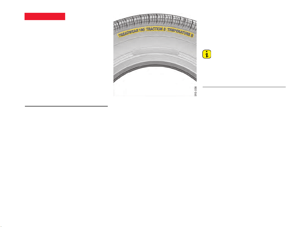
Minor Repairs 187
Driving with damaged tires could cause you to
lose control of the vehicle.
f If while driving, your vehicle experiences a
sudden vibration or ride disturbance, and/or
you suspect that possible damage to your tires
or vehicle has occurred, you should
immediately reduce your speed without
excessive use of the brakes.
f Stop the vehicle as soon as possible, and
inspect the tires.
If you cannot determine the cause for the
disturbance, have your vehicle towed to the
nearest Porsche or tire dealer to have your
vehicle or tire(s) inspected.
f Continuing to operate the vehicle without
correction could result in a loss of control.
Example
Uniform Tire Quality Grading
Quality grades can be found where applicable on
the tire sidewall between tread shoulder and
maximum section width.
All passenger car tires must conform to Federal
Safety Requirements in addition to these grades.
Treadwear
The treadwear grade is a comparative rating
based on the wear rate of the tire when tested
under controlled conditions on a specific
government test course. For example, a tire
graded 150 would wear one and a half (1-1/2)
times as well on the government course as a tire
graded 100. The relative performance of tires
depends upon the actual conditions of their use,
however, and may depart significantly from the
norm due to variations in driving habits, service
practices and differences in road characteristics
and climate.
Traction AA, A, B, C
The traction grades, from highest to lowest, are
AA, A, B, and C and they represent the tire's ability
to stop on wet pavement as measured under
controlled conditions on specified government
test surfaces of asphalt and concrete. A tire
marked C may have poor traction performance.
Information
The traction grade assigned to this is based on
braking (straight-ahead) traction tests and does
not include cornering (turned) traction,
acceleration, hydroplaning or peak traction
characteristics.
Temperature A, B, C
The temperature grades are A (the highest), B and
C, representing the tire's resistance to the
generation of heat and its ability to dissipate heat
when tested under controlled conditions on a
specified indoor laboratory test wheel.
Sustained high temperatures can cause the
material of the tire to degenerate and reduce tire
life, and excessive temperature can lead to
sudden tire failure.
The grade C corresponds to a level of
performance which all passenger car tires must
meet under the Federal Motor Vehicle Safety
Standard No. 109.
Grades B and A represent higher levels of
performance on the laboratory test wheel than the
minimum required by law.
Tire damage while
driving
DANGER
h

188 Minor Repairs
The temperature grade for this tire is established
for a tire that is properly inflated and not
overloaded. Excessive speed, underinflation, or
excessive loading, either separately or in
combination, can cause heat buildup and possible
tire failure.
f Do not exceed the permitted maximum speed
for the tires fitted to the vehicle.
f Ensure that the tires are set to the correct
inflation pressure.
f Observe the maximum load for the vehicle.
Tire pressures
Driving the vehicle with low tire pressure increases
risk of a tire failure and resulting loss of control.
Furthermore, low tire pressure increases rate of
wear of the affected tires and causes damage.
f Always use an accurate tire pressure gauge
when checking inflation pressures.
f Do not exceed the maximum tire pressure
listed on the tire sidewall. (Also refer to
“Technical data”).
f Please see the chapter “TIRE PRESSURE
PLATE” on page 189.
f Cold tire inflation pressure means: all tires
must be cold, ambient temperature maximum
68 °F (20 °C), when adjusting the inflation
pressure. Avoid sunlight striking the tires
before measuring cold pressures, since the
pressures would rise from temperature
influence.
f Valve caps protect the valve from dust and dirt,
and thus from leakage. Always screw caps
tightly down. Replace missing caps
immediately.
f Use only plastic valve caps.
f For safety reasons, don't use tire inflating
bottles.
f Please see the chapter “TIRE PRESSURE FOR
COLD TIRES (68 °F/ 20 °C)” on page 221.
Each tire, including the spare (if provided), should
be checked monthly when cold and inflated to the
inflation pressure recommended by the vehicle
manufacturer on the vehicle placard or tire
inflation pressure label. (If your vehicle has tires of
a different size than the size indicated on the
vehicle placard or tire inflation pressure label, you
should determine the proper tire inflation pressure
for those tires.)
As an added safety feature, your vehicle has been
equipped with a tire pressure monitoring system
(TPMS) that illuminates a low tire pressure telltale
when one or more of your tires is significantly
under-inflated. Accordingly, when the low tire
pressure telltale illuminates, you should stop and
check your tires as soon as possible, and inflate
them to the proper pressure. Driving on a
significantly under-inflated tire causes the tire to
overheat and can lead to tire failure. Under-
inflation also reduces fuel efficiency and tire tread
life, and may affect the vehicle’s handling and
stopping ability.
Please note that the TPMS is not a substitute for
proper tire maintenance, and it is the driver’s
responsibility to maintain correct tire pressure,
even if under-inflation has not reached the level to
trigger illumination of the TPMS low tire pressure
tell-tale.
For further information on the tire pressure
monitoring system:
f Please see the chapter “TIRE PRESSURE
MENU (TIRE PRESSURE MONITORING
SYSTEM, TPMS)” on page 86.
When tires are warm, the tire pressure is
increased.
f Never let air out of hot tires. This could cause
the tire pressure to fall below the prescribed
value.
Insufficient tire pressure can cause tires to over-
heat and thus be damaged – even invisibly. Hidden
tire damage is not eliminated by subsequently
correcting the tire pressure.
Overloading
Overloading can lead to dangerous vehicle
reactions and long braking distances.
f Do not overload your vehicle.
f If you plan to load the vehicle, first correct the
tire pressure. Tire pressure for loaded vehicle
can be found on the tire pressure plate and in
the chapter technical data.
f Never exceed the specified axle load.
Tire abuse
Low tir
e pressure
WARNING
h
DANGER
h
Overloading tires
DANGER
h
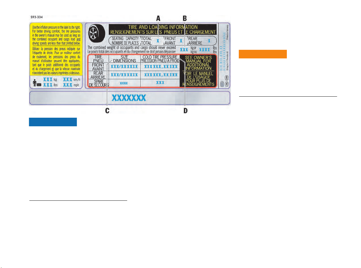
Minor Repairs 189
Risk of damage to the vehicle and to the tires.
Damage due to overloading is not covered by the
vehicle warranty.
Tire damage may also be caused by overloading,
and this damage is not covered by your tire
warranty.
f Do not overload your vehicle.
f If you plan to load the vehicle, first correct the
tire pressure. Tire pressure for loaded vehicle
can be found on the tire pressure plate and in
the chapter “Technical data“.
f Never exceed the specified axle load.
f Please see the chapter “LOADING
INFORMATION” on page 151.
Example of a tire pressure plate
Tire Pressure plate
Information on the tire pressure plate
A Seating capacity
Maximum number of vehicle occupants, including
the driver.
B Vehicle load limit
Is the maximum total weight limit specified of the
load (passengers and cargo) for the vehicle. This
is the maximum weight of passengers and cargo
that can be loaded into the vehicle.
f Please see the chapter “LOADING
INFORMATION” on page 151.
NOTICE
C Original tire size
Size of tires mounted at the factory.
D Recommended cold tire inflation pressure
These values are for cold tires (68 °F/20 °C).
Tire traction
When driving on wet or slushy roads, a wedge of
water may build up between the tires and the road.
This phenomenon is known as “hydroplane” and
may cause partial or complete loss of traction,
vehicle control or stopping ability.
f Reduce speed on wet surfaces.
Hydroplaning
WARNING
h

190 Minor Repairs
Tire life
Tire life depends on various factors, i.e., road
surfaces, traffic and weather conditions, driving
habits, type of tires and tire care.
f Inspect your tires for wear and damage before
driving off. If you notice uneven or substantial
wear, wheels might need alignment or tires
should be balanced or replaced.
Tire wear
The original equipment tires on your Porsche have
built-in tire wear indicators. They are molded into
the bottom of the tread grooves and will appear as
approximately 1/2 in. (12 mm) bands when the
tire tread depth is down to 1/16 of an in (1.6 mm).
When the indicators appear in two or more
adjacent grooves, it is time to replace the tires.
We recommend, however, that you do not let the
tires wear down to this extent.
Worn tires cannot grip the road surface properly
and are even less effective on wet roads.
In the United States, state laws may govern the
minimum tread depth permissible. Follow all such
laws.
Driving on worn tires can result in loss of control
of the vehicle and could cause serious personal
injuries or death.
f Do not drive with worn tires or tires showing
cuts or bruises as they may lead to sudden
deflation and loss of control which could cause
severe personal injury.
f Specialized high performance tires on high
performance sports cars exhibit more wear
than those on a family sedan, or even a high
performance sedan.
Therefore, it is important to check your tire
pressure and condition at least every two
weeks.
f If you notice that tires are wearing unevenly,
consult your authorized Porsche dealer.
Uneven wear may not always be due to improper
wheel alignment. It can be the result of individual
driving habits such as cornering at high speeds. If
the tire pressure is not checked and adjusted
regularly, abnormal tire wear can also occur.
Tire care
f Avoid damaging tires and wheel rims.
f If you must drive over a curb or other obstacle,
drive slowly and at an obtuse angle.
f Check tires for uneven wear and damage
before driving off.
f Remove embedded material.
f Replace worn or damaged tires immediately.
f Keep oil, fuel, brake fluid, etc. away from tires.
f Replace missing valve stem caps.
f Keep tires inflated correctly.
f Wash tires when washing the vehicle. Also
clean inner side of wheels.
f Do not use abrasive cleaners when washing
the wheels.
f Check wheel rims for corrosion.
f Remove road salt, if driving in winter.
Tire damage, puncture
f Please see the chapter “HIGH-PRESSURE
CLEANING EQUIPMENT, STEAM CLEANERS”
on page 175.
Driving the vehicle with low tire pressure increases
risk of a tire failure and resulting loss of control.
Furthermore, low tire pressure increases the rate
of wear of the affected tires.
f Check tires – including sidewalls – regularly for
foreign bodies, nicks, cuts, cracks and bulges.
f After driving off road, examine tires for signs
of damage such as cuts, tears, bulges or
foreign objects stuck in the tread. Replace a
damaged tire if necessary.
f Cross curb edges slowly and at right angles if
possible.
Avoid driving over steep or sharp curbs.
f In cases of doubt, have the wheel (particularly
the inner side) checked by an authorized
Porsche dealer.
In case of tire damage, where it is uncertain
whether there is a break in the ply with all its
consequences or tire damage caused by thermal
or mechanical overloading due to loss of pressure
or any other prior damage, we recommend that
the tire be replaced for safety reasons.
If one faulty tire is replaced it should be noted that
the difference in tread depth on one axle must not
exceed 30 %. Handling inconsistencies may
result.
f Recommendation: Replace both tires on one
axle so that no handling inconsistencies may
result due to different tread depths.
f Perform a visual inspection if necessary.
Excessively-worn tires
DANGER
h
Damaged tire check
DANGER
h
Minor Repairs 191
Tire replacements
f Use only tire makes and types tested by
Porsche.
If you do not use a Porsche recommended
replacement tire, make sure that you
purchase your new tires from a reputable tire
dealer and that the dealer complies with all
manufacturers warnings for those tires.
Only tires with the same manufacturer and
with the same specification code (e.g. “N0”,
“N1”…) should be mounted on the vehicle.
Before mounting new tires, check with your
Porsche dealer about the current release
status.
Use tires with “ZR” quality standards. There
are currently no standards concerning tire
strength at speeds above 150 mph (240 km/h).
Tires should be replaced no less than on one axle
at the time. Only tires of the same make and type
must be used. Mixed tires are not permissible and
will affect vehicle performance, safety, and can
affect vehicle warranty.
Authorized Porsche dealers can recommend the
most current replacement tire options for your
vehicle.
Initially, new tires do not have their full traction.
You should therefore drive at moderate speeds
during the first 60 - 120 miles (100 - 200 km).
Tires must always remain on the same side
of the vehicle.
When wheels are removed, the direction of
rotation and position of each wheel should be
marked.
If new tires are installed only on one axle, a
noticeable change in handling occurs due to the
different tread depth of the other tires. This
happens especially if only rear tires are replaced.
However, this condition disappears as the new
tires are broken in.
f Please adjust your driving style accordingly.
Installation of new tires should only be done by a
qualified tire technician.
Valves
Please observe the fitting and replacement
instructions:
f Only use genuine Porsche valves for the Tire
Pressure Monitoring (TPM).
f Check the TPM valves whenever the tires are
changed, and replace if necessary. We
recommend that you get a Porsche partner to
do this work as dealers have trained workshop
personnel and the necessary parts and tools.
f Protect valve inserts from soiling using valve
caps. Soiled valve inserts can cause a gradual
loss of air.
f Use only plastic valve caps.
Parking at the curb
Hard impacts against curbs (or traffic islands) are
dangerous and may cause hidden tire damage
which is not noticeable until later. Such damage
can result in accidents at high speeds. Depending
on the force of impact, the edge of the rim can
also be damaged.
f After such an impact, have the wheel checked
by an expert.
f If you must drive over a curb or other obstacle,
drive slowly and at an obtuse angle.
Exercise care when parking along curbs.
Information
Tire repairs are not permissible under any
circumstances.
Wheel alignment, wheel balancing
As a precaution, have wheels with summer tires
balanced in the spring, and those with mud and
snow tires before winter. Unbalanced wheels may
affect car handling and tire life.
Only the specified weights may be used for wheel
balancing.
Self-adhesive weights must not come into contact
with cleaning agents, since they could drop off.
Uneven tread wear indicates wheel imbalance. In
this event, the vehicle should be checked at an
authorized Porsche dealer.
If, during a trip, uneven running or vibrations occur
that could be caused by damage to tires or the
car, the speed must be reduced immediately, but
without braking sharply. If you continue your trip
without having the cause of the fault remedied,
you might lose control of your vehicle.
f Stop the vehicle and check the tires.
f If no cause for the fault can be found, drive
carefully to the nearest authorized Porsche
dealer.
Curb impact / tire
damage
DANGER
h
High-speed tire vibration
DANGER
h
192 Minor Repairs
Wheels with Tire Pressure Monitoring
System (TPMS) sensors
Before changing wheels, make sure that the
wheels are compatible with your vehicle’s TPMS.
f Check this with your authorized Porsche
dealer.
Removing and storing tires
f After changing, adjust tire pressure and torque
wheel bolts diagonally.
Please see the chapter “CHANGING WHEELS”
on page 196.
f Store tires in a cool and dry place. Rotate
periodically to avoid flat spots.
f Do not store summer tires or park vehicles
fitted with summer tires at ambient
temperatures below 5 °F (–15 °C).
f Avoid contact with fuel, oil and grease.
Tires must always remain on the same side
of the vehicle.
When wheels are removed, the direction of
rotation and position of each wheel should be
marked.
Example
FR (front right), FL, RR and RL.
Wheels must always be fitted in accordance with
their marking.
The perception that tire durability and
performance are not affected by storage and age
is unfounded.
Chemical additives, which make the rubber
elastic, lose their effectiveness over the course of
time and the rubber becomes brittle and cracks.
Therefore, the tires should be inspected from
time to time.
Information
Under no circumstances should tires older than
6 years be used on your Porsche.
The age of the tire can be obtained from the “DOT”
code number. If, for example, the last four
numbers read 1211, then the tire was produced in
the 12th week of 2011.
Snow tires
The installation of Porsche approved snow tires is
recommended.
Use Porsche approved snow tires for grip on snow
and ice. Summer performance tires are not
suitable for usage in cold, snowy, or icy
conditions.
Check with your local Motor Vehicle Bureau for
possible restrictions.
The standard tires profile and rubber mixture are
optimized for wet and dry driving conditions, and
may not prove favorable for snow conditions.
f Install snow tires before driving in such
conditions.
Risk of insufficient road grip leading to loss of
control and damage to the vehicle.
The standard tires profile and rubber mixture are
optimized for wet and dry driving conditions, and
may not prove favorable for snow conditions.
f Install snow tires before driving in such
conditions.
Before mounting snow tires, consult with your
Porsche dealer. They have the technical
information necessary to advise you on wheel and
tire compatibility.
f Snow tires should have the same load capacity
as original equipment tires and should be
mounted on all four wheels.
Driving the vehicle with low tire pressure increases
risk of a tire failure and resulting loss of control.
Furthermore, low tire pressure increases the rate
of wear of the affected tires and causes damage.
Tires with badly worn treads are very dangerous
and could cause accidents.
f Make sure they are replaced immediately.
f Do not exceed the snow tire speed rating.
Snow tires do not have the same degree of
traction on dry, wet or snowfree roads as normal
tires.
Furthermore, snow tires wear rapidly under these
conditions.
Snow tire use
WARNING
h
NOTICE
Tire hazards
DANGER
h

Minor Repairs 193
Information
We recommend that you fit snow tires on the
vehicle at temperatures below 45 °F (7 °C) since
the driving performance of summer tires is
reduced at low temperatures and a lower level of
comfort can also be expected. For example,
juddering noises caused by the tires can occur
while maneuvering the vehicle or accelerating out
of bends on both dry and wet road surfaces.
Extremely low temperatures of
below 5 °F (–15 °C) can cause permanent
damage to summer tires.
Snow tires lose their suitability when their tread
depth falls below 5/32 in. (4 mm).
Comply with all state and local laws
governing snow tire and tread depth
requirements.
Exceeding the maximum permitted speed for the
tires fitted could cause tire failure.
f Always check the maximum speed rating on
the tire sidewall on any tire on the vehicle.
f Never exceed the maximum speed rating of
the tires.
Wheel change
f When wheels are removed, mark the direction
of rotation and position of each wheel.
Example: FR (front right), FL, RR and RL.
f Always fit the wheels in accordance with the
markings.
Snow chains
Risk of damage to body, axle or brake
components.
f Fit snow chains only to the rear wheels, and
only with the tire/rim combination listed in the
Technical Data.
f Use only the fine-link snow chains
recommended and authorized by Porsche so
that sufficient clearance between the wheel
well and the chain is assured.
f Please see the chapter “WHEELS, TIRES”
on page 220.
f Follow instructions issued by the supplier of
the chains.
Fitting snow chains
Using snow chains is not permitted if 1/5 in.
(5 mm) spacers are fitted.
f To permit the fitting of snow chains, have the
5 mm spacers removed on all 4 wheels.
f Before fitting chains, remove accumulated ice
and snow from the wheel well.
f Vehicles with snow chains must not be driven
faster than 30 mph (50 km/h).
Different states and countries have varying
statutory requirements regarding maximum
speed.
f Check with local authorities for possible
restrictions.
f Remove chains as soon as the roads are free
of ice and snow.
f
Excessive speed for
tires
DANGER
h
NOTICE
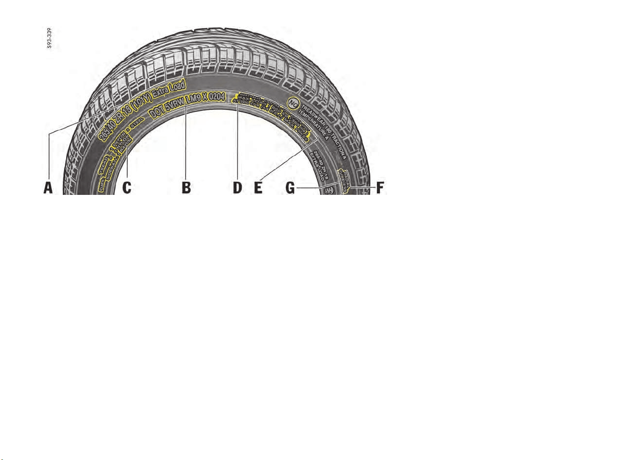
194 Minor Repairs
Example of Inscription
Inscription on radial tire
A – Tire size
Example: P 265/40ZR18 (101Y)
– P - The tire is designed for Passenger vehicle.
This information is not included on all tires.
– 265 - Indication of tire width in mm
– 40 - Indication of tire height to tire width ratio
in percent
– ZR - Belt type code letter for radial
– 18 - Indication of rim diameter in inches
– 101 - Load capacity coefficient
– Y - Speed code letter
– XL (Extra Load) - Tire with increased load
rating
B – TIN (Tire Identification Number)
Example: DOT xx xx xxxx xxxx
– DOT
The DOT symbol indicates that the tires
comply with the requirements of the
US Department of Transportation and provides
information about:
– first two-digit code means manufacture’s
identification mark.
– second two-digit code means tire size.
– third four-digit code means tire type code.
– fourth four-digit code means date of
manufacture.
If, for example, the last four numbers read
0211, the tire was produced in the 2nd week
of 2011.
C – Tire ply composition and material
The number of layers in the tread and sidewalls
and their material composition.
D – Maximum permissible inflation pressure
The maximum permissible cold inflation pressure
to which a tire can be inflated.
f Do not exceed the permissible inflation
pressure.
E – Maximum Load rating
The maximum load in kilograms and pounds can
be carried by the tire. If you replace tires always
use a tire that has the same maximum load rating
as the factory installed tire.
F – Radial
The identification indicates if the tire has radial
structure.
G – Term of tubeless or tube tire
Identification for tubeless tires.
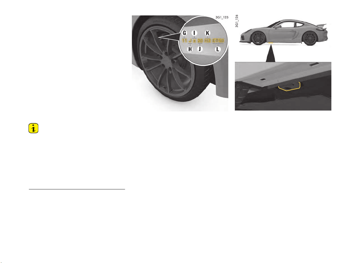
Minor Repairs 195
Speed code letters
The speed code letter Y indicates the maximum
permitted speed for the tire.
This code letter is shown on the tire sidewall.
Information
Tires with a maximum speed rating that is lower
than the specified maximum vehicle speed may be
mounted only if they bear an M+S identification on
the tire sidewall.
f Please note that in addition to snow tires,
all-season tires are also subject to speed limits
and bear this identification.
f Never drive faster than the speed rating of the
tires, and obey all speed and traffic laws.
G - Rim width in inches
H - Rim-flange contour code letter
I - Symbol for drop-center rim
J - Rim diameter in inches
K - Double hump
L - Rim offset in mm
Inscription on alloy wheels
The information is provided on the rear of the
spokes. The rim width in inches A and the rim
offset F are visible from the outside. This
information can be found near the tire valve.
Jacking point for lifting platform and jack at the front
Raising the vehicle with a lifting platform,
trolley jack or standard jack
f Before driving the vehicle onto a lifting
platform, make sure that there is sufficient
space between the lifting platform and the
vehicle.
T up to 118 mph (190 km/h)
H up to 131 mph (210 km/h)
V up to 150 mph (240 km/h)
W up to 165 mph (270 km/h)
Y up to 185 mph (300 km/h)
(Y) up to 185 mph (300 km/h) as for Y tires.
Speeds of more than 185 mph
(300 km/h) are also possible at a
maximum tire load capacity of 85 %
(confirmation from tire manufacturer
required for speeds of more than
185 mph (300 km/h)).
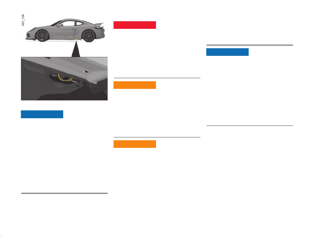
196 Minor Repairs
Jacking point for lifting platform and jack at the rear
Risk of serious damage to the engine or vehicle if
you lift the vehicle improperly.
f Lift only at the jacking points provided.
f Before driving the vehicle onto a lifting
platform, make sure that there is sufficient
space between the lifting platform and the
vehicle.
f To avoid serious damage, never jack up the
vehicle at the engine, transmission or at the
axles.
f Use only level anti-slip rubber pads on a lifting
platform.
f Do not damage any sensitive components in
the vicinity of the jacking points.
Changing Wheels
Other vehicles could collide with your vehicle if you
are parked in a dangerous position.
f If you have a flat tire, move a safe distance off
the road. Turn the emergency flasher on and
use other warning devices to alert other
motorists.
f Do not remain in the car. Someone
approaching from the rear may not realize your
vehicle is stopped and cause a collision.
Exhaust fumes and the exhaust system are very
hot when the engine is running. The exhaust
system remains hot for some time after the
vehicle is turned off.
f Do not park your vehicle in areas where the hot
exhaust system may come in contact with dry
grass, brush, fuel spill or other flammable
material.
If the vehicle is not secured, or incorrectly
secured, during a wheel change, it could move
unexpectedly or fall from the car jack.
f Passengers must not be in the vehicle when it
is jacked up.
f Before you change a wheel, be sure the ground
is level and firm. If necessary, use a board
under the jack to ensure that the jack does not
sink into the ground.
f Set the electric parking brake and block the
wheels opposite the flat tire on the other side
of the vehicle.
f The jack is only to be used for changing a
wheel. Do not use it as a support to work under
the car.
f The car must be jacked up only at the
illustrated jacking points. Lifting at any other
place may result in personal injury.
Risk of damage to the engine or vehicle if you lift
the vehicle improperly.
f The car must be jacked up only at the
illustrated jacking points. Lifting at any other
place may result in damage to the vehicle.
f Never jack up the car by the body, bumpers,
engine, transmission or at the axles.
f Do not damage any sensitive components in
the vicinity of the jacking points.
f For safety reasons do not use tire inflating bot-
tles. Do not use commercially available sealant
bottles. Use only the tire inflating bottle
located in the luggage compartment.
NOTICE
Unsafe stopping
Stopping over nearby
flammable matter
Jacking risks
DANGER
h
WARNING
h
WARNING
h
NOTICE
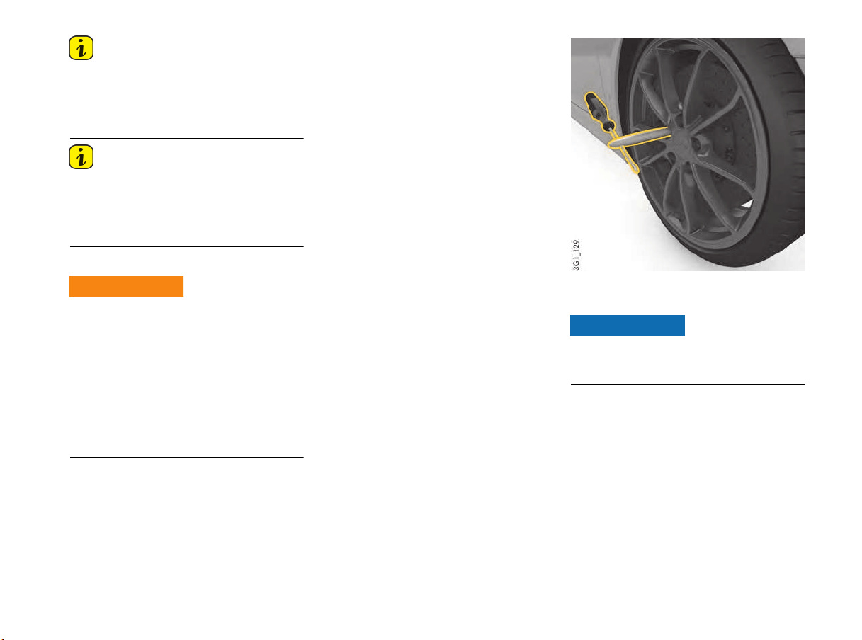
Minor Repairs 197
Information
The tools required for changing a wheel (e.g. jack,
wheel bolt wrench, assembly aids) are not
supplied as standard with the vehicle. Your
authorized Porsche dealer will be pleased to
advise you.
Information
The tire and wheel sizes on both axles are
different.
f Do not fit the wrong wheels on the wrong axle.
f Only use wheels/tires with approved
dimensions for the relevant axle.
Sequence of operation
The jack must be used only to raise the car for
wheel changing.The jack must never be used as a
support to work underneath the vehicle. If the jack
is accidentally dislodged, you or bystanders could
suffer severe personal injury.
f Never jack up other vehicles or other loads
with the jack.
f Always place the car on stable supports if you
have to work under it. When working under the
vehicle, always use safety stands specifically
designed for this purpose.
f Please use a suitable knee rest to protect your
clothing against soiling.
1. Activate the electric parking brake and shift
into 1st gear.
2. Switch on the emergency flasher if necessary.
3. Secure the vehicle to prevent it from rolling
away, e.g. by means of wedges under the
wheels on the opposite side.
This is particularly important on slopes.
4. Slightly loosen the wheel bolts on the wheel to
be changed.
5. Lift the vehicle only at the specified jacking
points.
6. Raise the vehicle until the wheel lifts off the
ground.
f Please see the chapter “RAISING THE VEHICLE
WITH A LIFTING PLATFORM, TROLLEY JACK
OR STANDARD JACK” on page 195.
7. Remove 1 or 2 wheel bolts (see corresponding
figure).
Screw in one assembly aid on vehicles without PCCB
8. Screw in assembly aids instead of wheel bolts.
Risk of damage to brake disks.
f Always screw in both assembly aids when
changing a wheel.
9. Remove the remaining wheel bolts.
10.Take the wheel off and put a new wheel on.
f Please see the chapter “WHEEL BOLTS”
on page 199.
11.Insert wheel bolts and tighten by hand.
Working under vehicle
WARNING
h
NOTICE
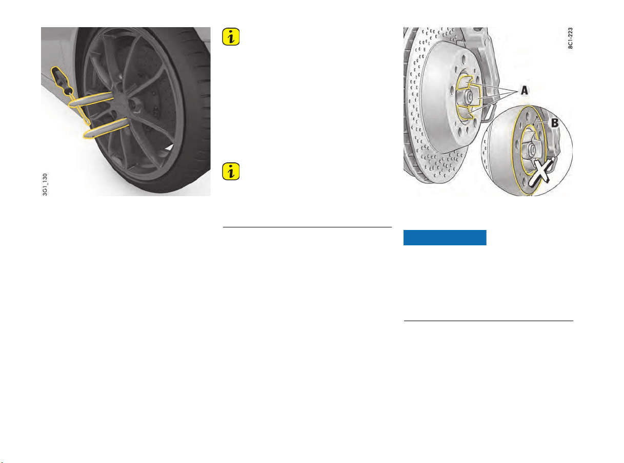
198 Minor Repairs
Screw in two assembly aids on vehicles with PCCB
12.Remove assembly aids and screw in remaining
wheel bolts.
Initially tighten bolts only slightly in diagonally
opposite sequence so that the wheel is
centered.
13.Inflate the tire if necessary.
f Please see the chapter “TIRE PRESSURE FOR
COLD TIRES (68 °F/ 20 °C)” on page 221.
14.Lower the vehicle fully and remove the jack.
15.Tighten wheel bolts in diagonally opposite
sequence.
Immediately after changing a wheel, use
a torque wrench to check the prescribed
tightening torque of the wheel bolts
(160 Nm/118 ftlb.).
Information
Tire Pressure Monitoring System settings on the
multi-function display must be updated after a
wheel change.
f Please see the chapter “TIRE PRESSURE
MENU (TIRE PRESSURE MONITORING
SYSTEM, TPMS)” on page 86.
Checking tire pressure with a pressure
gauge
1. Remove the valve stem cap from the tire.
2. Press the pressure gauge onto the valve stem.
Information
f Do not press too hard or force the valve stem
sideways, or air will escape.
If the sound of air escaping from the tire is
heard, reposition the pressure gauge.
3. Read the tire pressure on the gauge stem and
compare it to the permissible tire pressure.
This information can be found on the tire
pressure plate or in the chapter Technical
Data.
4. Remove the pressure gauge.
5. Please see the chapter “TIRE PRESSURE
MENU (TIRE PRESSURE MONITORING
SYSTEM, TPMS)” on page 86.
Do not grease wheel attachment face B
Wheel Attachment Faces
There is a risk of damage to the wheel and wheel
attachment face.
f The wheel attachment face B on the brake disk
and on the wheel itself must not be greased.
f Only the areas A may be greased. Grease
these areas very thinly with Optimoly
®
TA.
Do not use any other grease/paste.
NOTICE
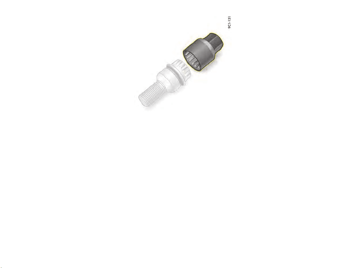
Minor Repairs 199
Wheel Bolts
f Always clean the wheel bolts before fitting.
f Wheel bolts must not be greased.
f Replace damaged wheel bolts.
Only use genuine Porsche wheel bolts
assigned especially to this model or wheel
bolts of similar quality that have been
manufactured according to Porsche
specifications and production requirements.
Tightening torque
Tightening torque for wheel bolts: 160 Nm
(118 ftlb.).
Security wheel bolts
The adapter (wrench socket) supplied for the
security wheel bolts (if fitted) can be stored in
the tool kit in the front luggage compartment.
f If the wheels have to be removed at the
workshop, do not forget to hand over the
socket for the security wheel bolts along with
the car key.
f To loosen or tighten the wheel bolt with anti-
theft protection, the adapter must be used
between the wheel bolt and the wheel bolt
wrench.
f When positioning the wrench socket, ensure
that it engages fully in the teeth of the wheel
bolt.
Flat Tire
1. Stop the vehicle as far away from the driving
lane as possible.
The vehicle must be parked on a firm and flat
surface offering adequate grip.
2. Switch emergency flasher on.
3. Apply the parking brake.
4. Put the vehicle in 1st gear.
5. Straighten the front wheels.
6. Remove the ignition key, in order to lock the
steering and prevent the engine from being
started.
7. Get all passengers to leave the vehicle.
8. Set up the warning triangle at a suitable
distance.
Filling in tire sealant
The tire sealant can be found in the right-hand box
in the front luggage compartment. The
compressor is located under the cover in the front
luggage compartment.
The tire sealant can be used to seal small cuts,
especially in the tire tread.
Sealing the tire with the tire sealant is only an
emergency solution so you can drive to the
nearest workshop. Even if the tire is air-tight,
it may only be used for short journeys in an
emergency.
The tire sealant set comprises:
– a filler bottle
– a filler hose
– a valve turner
– a spare valve insert
– a sticker with the maximum permitted speed
– a compressor
– operating instructions
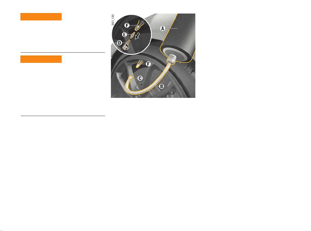
200 Minor Repairs
Always observe the following points:
f Use the tire sealant only in the case of cuts or
punctures no larger than 0.15 in. (4 mm).
f Never use the tire sealant if the rim is
damaged.
The sealant is highly flammable and harmful to
health.
f Fire, naked flame and smoking are prohibited
when handling tire sealant.
f Avoid contact with skin, eyes or clothing due to
caustic chemical properties of the tire sealant.
f Keep tire sealant away from children.
f Do not inhale vapors, due to the consequent
harm to personal health resulting in serious
personal injury or death.
In the event of contact with sealant:
f If sealant gets on your skin or into your eyes,
thoroughly rinse the affected part of your body
immediately with plenty of water.
f Change soiled clothing immediately.
f See a doctor immediately in the event of an
allergic reaction.
f If sealant is swallowed, thoroughly rinse out
the mouth without delay and drink plenty of
water. Do not induce vomiting.
See a doctor immediately.
A - Filler bottle
B - Filler hose
C - Filler hose plug
D - Valve turner
E - Valve insert
F - Tire valve
Filling in sealant
1. Leave the object that caused the puncture in
the tire.
2. Remove sealant and the enclosed sticker from
the front luggage compartment.
3. Stick the sticker in the driver’s field of vision.
4. Shake filler bottle A.
5. Screw filler hose B onto the filler bottle.
The filler bottle is now open.
6. Unscrew valve cap from the tire valve F.
7. Remove valve insert E from the tire valve with
valve turner D.
Keep the valve insert in a clean, dry place.
8. Remove plug C from the filler hose B.
9. Push filler hose onto the tire valve.
10.Hold the filler bottle higher than the level of the
tire valve and squeeze it forcefully until the
bottle is completely emptied into the tire.
11.Pull filler hose off the tire valve.
12.Screw valve insert E securely into the tire
valve with the valve turner D.
13.Connect the compressor to a socket in the
vehicle and inflate the tire to at least 37 psi/
2.5 bar/25 kPa.
If this tire pressure cannot be reached, the tire
is too severely damaged.
Do not continue driving with this tire.
14.Screw valve cap onto the tire valve F.
15.Check the tire pressure after driving for
around 10 minutes.
If the tire pressure is less than 22 psi/1.5 bar/
15 kPa, do not continue driving.
If a value of more than 22 psi/1.5 bar/15 kPa
is indicated, correct the pressure to the
prescribed value.
f Please see the chapter “TIRE PRESSURE FOR
COLD TIRES (68 °F/ 20 °C)” on page 221.
16.Please contact an authorized Porsche dealer.
f Also follow the separate operating instructions
for the tire sealing compound.
Limits on tire sealant
use
Tir
e sealant flammability
WARNING
h
WARNING
h
Minor Repairs 201
A tire pressure sensor that is soiled with sealant
cannot determine the tire pressure correctly.
f When the defective tire is replaced, the tire
pressure sensor must be replaced.
Damaged tires could burst causing loss of control
of the vehicle.
f Have the tire replaced by a specialist
workshop as soon as possible.
f Avoid hard acceleration and high cornering
speeds.
f Observe maximum speed of 50 mph
(80 km/h).
f Always observe the safety and operating
instructions, which can be found in the
separate operating instructions for the sealant
and on the compressor.
Electrical System
In order to avoid damage and faults in electrical or
electronic systems, electrical accessories should
be installed at an authorized Porsche dealer
f Use only accessories approved by Porsche.
Replacing fuses or relays with the engine running
or the ignition on could cause electrical shock.
f Disconnect the negative terminal on the
battery during all work on the electrical
system.
f Please see the chapter “BATTERY (12 VOLT)”
on page 205.
Relays
Relays should be checked or changed only at an
authorized workshop.
Changing fuses
In order to prevent damage to the electrical
system due to short circuits and overloads,
the individual circuits are protected by fuses.
The fuse boxes are located in the side walls of the
driver’s and passenger’s footwell respectively.
1. Switch off the load with the defective fuse.
2. Detach the appropriate plastic cover at the
finger hole.
3. Remove the relevant fuse (see fuse
assignment) from its slot using the yellow
plastic gripper A (left fuse box) in order to
check it.
A blown fuse can be identified by the melted
metal strip.
4. Replace only with fuses of the same rating.
Spare fuses can be found in the left-hand fuse
box, next to the yellow plastic gripper.
We recommend that you use genuine Porsche
fuses for replacement.
Information
If a fuse blows repeatedly, the cause of the fault
must be corrected immediately.
f Please contact an authorized Porsche dealer.
Pressure loss
Damaged tires
WARNING
h
DANGER
h
Changing fuses
WARNING
h
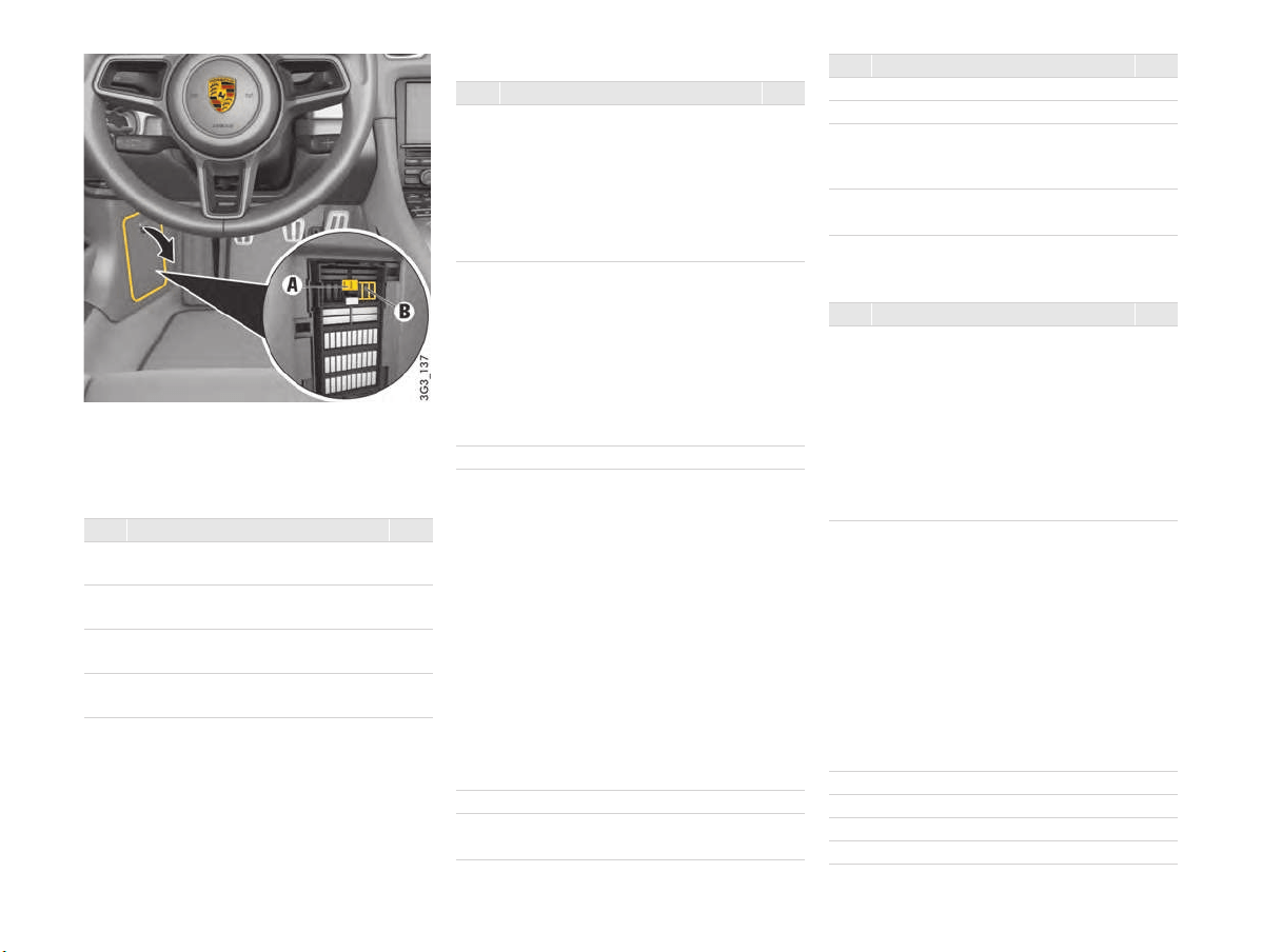
202 Minor Repairs
A - Plastic gripper
B - Spare fuses
Fuses in left footwell
Row A
Row B
Row C
No. Designation A
1 Lower left:
Air-conditioning fan, R/L
40
2 Upper left:
PSM control unit
40
3 Lower right:
Seat adjustment
25
4 Upper right:
PASM control unit
40
No. Designation A
1 Headlight adjustment for LHD/RHD
Front lid light
Front lid actuator
High beam, FL
Low beam, FL
Side marker light, FR
Turn signal lights, RL
40
2 Exhaust flap control
Raised brake light, rear wing
Rear lid actuator
Rear fog light, right
Reversing light, left
Brake light, left
Tail light, left
Daytime driving light, FL
15
3 Alarm horn 15
4 Interior lighting
Hall sensors
Orientation light
License plate light
Heated rear window relay
Central locking LED
Door panels LED
Ambient light
Raised brake light
Rear fog light, left
Brake light, right
Reversing light, right
Daytime driving light, FR
Tail light, right
15
5 Fuel pump relay 20
6 Filler flap close/open
Washer pump
10
7 Not used
8 Air conditioning control unit 7.5
9 Instrument cluster
Steering column
Stopwatch
10
10 PCM
CAN adapter
25
No. Designation A
1 Center console button panel
Gateway control unit
Diagnostic socket
Ignition lock
Passenger compartment monitoring
sensor
Light switch
Front left door control unit
Bluetooth phone charger
15
2 Footwell lights
Electric ignition lock anti-removal
lock
Turn signal light indicator, FL/FR
Emergency flasher button LED
Electric ignition lock light
Side turn signal lights, FR/FL
High beam, FR
Low beam, FR
Turn signal light indicator, RR
Side marker light, FL
40
3 Vehicle Tracking System control unit 5
4 Horn 15
5 Filler flap 30
6 Power window control unit, FL 25
No. Designation A
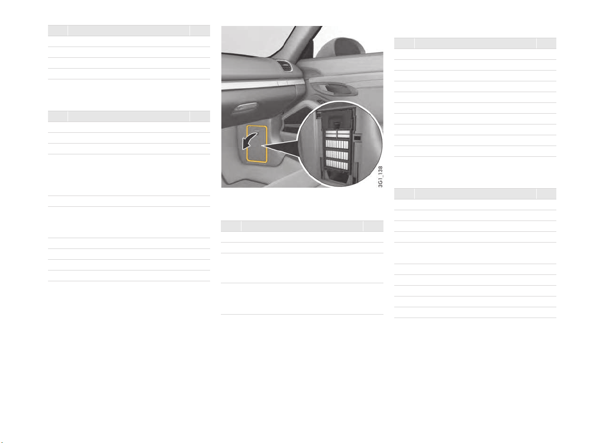
Minor Repairs 203
Row D
Fuses in right footwell
Row A
Row B
Row C
7 Headlight cleaning system 30
8 PSM control unit 25
9 Alarm siren 5
10 PASM control unit 5
No. Designation A
1 Not used
2 HomeLink
®
5
3 Left headlight 5
4 PDC control unit
Gateway/diagnostic socket
Air quality sensor
Gateway headlights
5
5 PSM control unit 5
6 Steering column switching module
Electronic steering gear
Refrigerant pressure sensor
5
7 Clutch switch sensor 5
8 Right headlight 5
9 Interior mirror 5
10 Not used
No. Designation A
No. Designation A
1 Not used 40
2 Not used 40
3 Lower right:
Fresh-air blower motor
Blower regulator
40
4 Upper right:
Right seat control unit
Seat adjustment
25
No. Designation A
1 Rain sensor 5
2 Air conditioning control unit 25
3 Not used
4 Not used
5 RDK control unit 5
6 TV tuner 5
7 Not used
8 Not used
9 Not used
10 Not used
No. Designation A
1 Heated rear window 30
2 Electric parking brake button 5
3 PASM control unit 5
4 Not used
5 Temperature sensor
Tank leakage diagnosis
5
6 Wiper motor 30
7 Power window control unit, FR 25
8 Steering column adjustment 25
9 Roof console 5
10 Not used
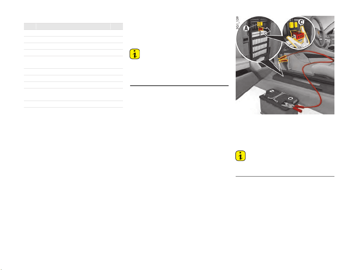
204 Minor Repairs
Row D Emergency unlocking of front luggage
compartment lid
If the battery is discharged, the front luggage
compartment lid can be opened only with the
aid of a donor battery.
Information
The engine cannot be started with this method.
f Please see the chapter “EXTERNAL POWER
SUPPLY, EMERGENCY STARTING WITH
JUMPER CABLES” on page 207.
Unlocking lids
1. Use the key to unlock the vehicle at the
door lock.
2. Remove the plastic cover from the left-hand
fuse box.
3. Pull out positive terminal C (red) in the fuse
box using the plastic gripper A (yellow).
A - Plastic gripper (yellow)
C - Positive terminal (red)
4. Use the red jump lead to connect the positive
terminal of the donor battery to the positive
terminal C in the fuse box.
Information
If the vehicle was locked, the alarm horn will sound
when the negative lead is connected.
No. Designation A
1 Airbag control unit 5
2 PASM control unit 5
3 Not used
4 Not used
5 Occupant sensing for the
passenger's seat
5
6 Not used
7 Control units DME, VTS, BCM back 5
8 Socket in passenger footwell 20
9 Center console socket
Cigarette lighter
20
10 Socket in glove box 20
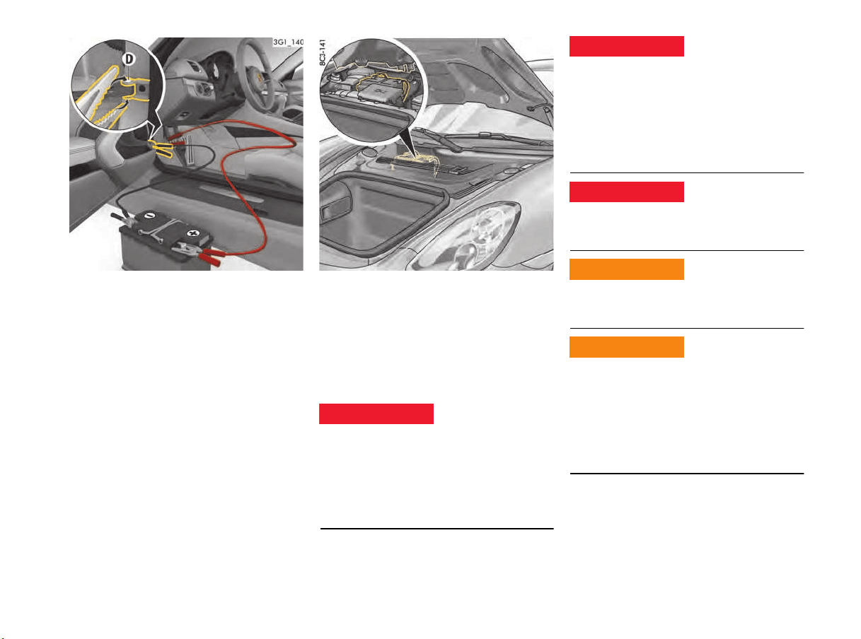
Minor Repairs 205
5. Use the black jump lead to connect the
negative terminal of the donor battery to the
door arrester D.
6. Press button 2 on the remote control for
approx. 2 seconds to unlock the luggage
compartment lid. The alarm system is
switched off.
7. Disconnect the negative lead first, then the
positive lead.
8. Push positive terminal C into the fuse box and
fit the plastic fuse box cover.
Battery (12 volt)
The battery is located under the cover in the front
luggage compartment.
For information on removing the cover:
f Please see the chapter “TIRE FILLING
COMPRESSOR” on page 148.
f Have the battery removed and installed only by
your authorized Porsche dealer.
f Observe all warning notes on the battery.
f Disconnect the negative terminal on the
battery during all work on the electrical
system.
f Do not lay tools or other metal objects on the
battery as they could cause a short circuit
across the battery terminal.
f Charge battery in a well vetilated area.
f Never charge a frozen battery. It may explode
because of gas trapped in the ice. Allow a
frozen battery to thaw out first.
f Do not expose the battery to an open flame,
electrical spark or a lit cigarette, since they
can ignite hydrogen gas from the battery.
f Do not wipe the battery with a dry cloth.
f Before touching the battery, discharge any
static electricity by touching the vehicle.
f After handling battery, always protect your skin
and remove surface chemicals by washing
thoroughly with soap and water.
f Wear eye protection.
f Do not allow battery acid to come in contact
with your skin or eyes.
f If you get electrolyte, which is an acid, in your
eyes or on your skin, immediately rinse with
cold water for several minutes and call a
doctor.
Electric shock
DANGER
h
Battery explosion
hazard
Static electricity
Chemical exposure
Battery acid and
electrolyte exposure
DANGER
h
DANGER
h
WARNING
h
WARNING
h
206 Minor Repairs
Risk of damage to the fabric, metal or paint from
battery acid or electrolyte.
f Do not allow battery acid to come in contact
with fabric or painted surfaces.
f Spilled electrolyte must be rinsed off at once
with a solution of baking soda and water to
neutralize the acid.
Charge state
A well-charged battery prevents starting problems
and has a longer service life.
In order to avoid unintentional battery
discharge:
f Switch off unnecessary electrical loads in city
traffic, on short trips or in a line of traffic.
f Always remove the ignition key when leaving
the vehicle or
f Avoid using the Porsche Communication
Management system and the audio system
when the engine is not running.
f Please see the chapter “CHARGING THE
BATTERY” on page 208.
Information
In the cold season in particular or if the vehicle
is used primarily for short distances, it may be
necessary to recharge the battery from time to
time.
Battery care
f Ensure that battery is securely mounted.
f Keep battery surface clean and dry.
f Keep terminals and connections clean.
Corrosion can be prevented by coating the
terminals and connections with petroleum jelly
or silicone spray.
f Ensure that terminal clamps and the vent
hose are firmly secured.
Winter driving
The ability of the battery to deliver and store
power decreases at low outside temperatures.
Moreover, the battery is more heavily loaded in the
winter months, e.g. by the heated rear window,
the more frequent use of additional lights, the
blower and the windshield wipers, etc.
f Have the battery checked before the start
of winter.
Information
Keep the battery fully charged to prevent it from
freezing.
A discharged battery can already freeze at 23 °F
(–5 ºC), but a fully charged one only freezes at
–-40 °F (–-40 ºC).
f If the battery is frozen, thaw it out before
connecting jump leads.
Storing the vehicle
If the vehicle is left for long periods in the garage
or workshop, the doors and lids should be closed.
f Remove the ignition key or disconnect the
battery if necessary.
Information
f When the battery is disconnected, the alarm
system ceases to function.
If the vehicle was locked before the battery
was disconnected, the alarm will be triggered
when the battery is reconnected.
To deactivate the alarm system:
f Lock the vehicle and unlock it again.
Alarm system, central locking
f The status of the central locking and alarm
system does not change when you disconnect
the battery.
Information
Even if you put your vehicle out of operation, the
battery still discharges.
f The battery must be charged, i.e. connected
to a charger, approximately every 6 weeks in
order to preserve battery function.
f Store a battery that has been removed in
a dark, cool place that is not exposed to frost.
NOTICE

Minor Repairs 207
Replacing the battery
The battery is subject to normal wear: its service
life depends heavily on the care you give it,
climatic conditions and the conditions of use
(distances, loads).
It is not possible to use the details on the battery
case to determine a comparable battery that
meets all the specific requirements of Porsche.
f Have the battery removed and installed only by
your authorized Porsche dealer.
f Only use an original Porsche battery, with the
correct part number, as a replacement. Only
this battery meets the specific requirements of
the vehicle.
f After you install a new battery, it must be
initialised in the control unit.
Please contact your authorized Porsche
dealer.
f Please observe the disposal instructions for
batteries.
Putting vehicle into operation
After connecting the battery or changing an
exhaustively discharged battery there are a few
simple steps necessary:
1. Store the end position for the power windows.
For information on storing the end positions for
the power windows:
f Please see the chapter “STORING END
POSITION OF THE WINDOWS AFTER
CONNECTING THE VEHICLE BATTERY”
on page 62.
2. Teach tires.
For information on teaching the Tire Pressure
Monitoring System:
f Please see the chapter “TIRE PRESSURE
MENU (TIRE PRESSURE MONITORING
SYSTEM, TPMS)” on page 86.
3. Store end position on vehicles with a slide/tilt
roof.
For information on storing the end position for
the slide/tilt roof:
f Please see the chapter “STORING END
POSITION OF THE WINDOWS AFTER
CONNECTING THE VEHICLE BATTERY”
on page 62.
External Power Supply, Emergency
starting with jumper cables
If the battery is flat, the battery of another vehicle
can be used for starting or as an external power
supply with the help of jump leads.
Both batteries must be 12 V batteries. The
capacity (Ah) of the donor battery must not be
substantially less than that of the flat battery.
The flat battery must be connected correctly to
the vehicle’s electrical system.
A short circuit may be caused if unsuitable jumper
cables are used or if jumper cable starting is not
performed properly. Such short circuits can
cause a fire.
f Use only standard jumper cables with sufficient
cross section and completely insulated
alligator clips. Follow the instructions provided
by the jumper cable manufacturer.
f Route the jumper cables so that they cannot
be caught by moving parts in the engine
compartment.
The jumper cables must be long enough so
that neither vehicles nor cables touch another.
f The vehicles must not touch, otherwise current
might flow as soon as the positive terminals
are connected.
f Ensure that tools or conductive jewelry (rings,
chains, watch straps) do not come into contact
with the positive jumper cable, the positive
battery post or live parts of the vehicle.
f Improper hook-up of jumper cables can ruin
the alternator.
Jumper cable hazards
WARNING
h
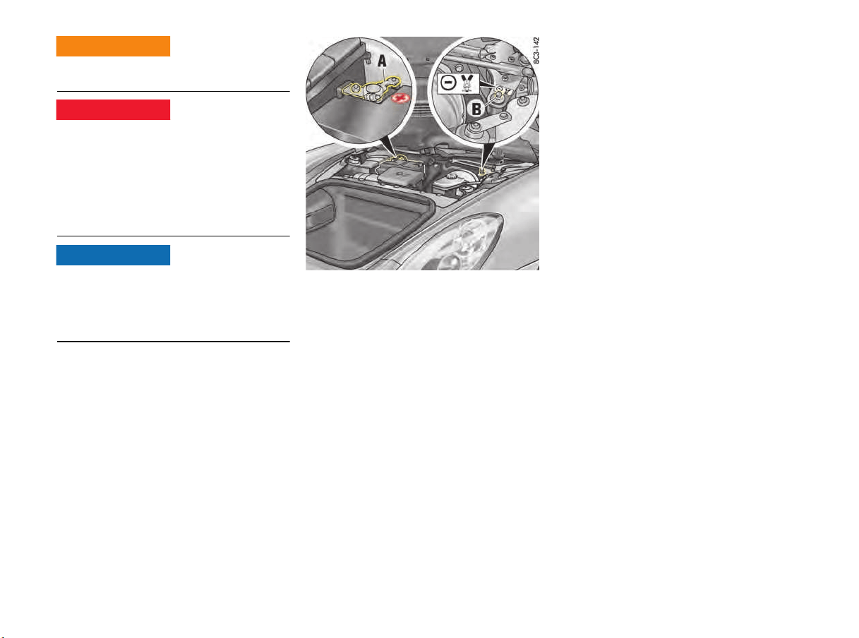
208 Minor Repairs
f Do not lean over the battery due to danger of
chemical burns from leaking acid.
f Improper use of booster battery to start a
vehicle may cause an explosion.
f Keep sources of ignition away from the
battery, e.g. naked flame, burning cigarettes
or sparks due to cable contact.
f Before connecting jumper cables, it is
essential to thaw out a frozen battery.
Risk of damage due to short circuit.
f Never connect jumper cables directly to the
battery. Always connect jumper cables to the
emergency starting terminals in the luggage
compartment.
+ = Battery positive terminal A
– = Ground point for external power supply/emergency
starting B
Supplying external power/
Performing emergency starting with
jumper cables
Always observe the sequence below:
1. Remove cover in front luggage compartment.
To remove the cover:
Please see the chapter “TIRE FILLING
COMPRESSOR” on page 148.
2. Connect the positive lead (red) to the positive
terminal A of the discharged battery first, then
connect it to the positive terminal of the donor
battery.
3. Connect the negative lead (black) first to the
negative terminal of the donor battery, then to
the ground point B.
4. Leave the engine of the donor vehicle running
at a higher engine speed.
5. Start the engine.
An attempted start using jump leads should
not last more than 15 seconds. Then wait for
at least one minute.
6. With engine running:
Disconnect the negative lead from the ground
point B first, then from the negative terminal of
the donor battery.
7. With engine running:
Disconnect the positive lead from the positive
terminal of the donor battery first, then from
the positive terminal A of the discharged
battery.
Charging the battery
Automotive batteries lose their efficiency when
not in use. The charge available in your battery can
be measured with a battery hydrometer. We
recommend that the battery voltage be tested by
your authorized Porsche dealer who has the
appropriate equipment.
If the car is not driven for prolonged periods, the
battery must be charged at least every 6 weeks.
A discharged battery allows rapid formation of
sulfates, leading to premature deterioration of the
plates.
Battery acid leakage
Battery char
ging and
jumping hazards
WARNING
h
DANGER
h
NOTICE
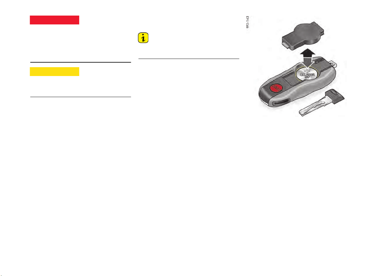
Minor Repairs 209
f Charge battery in a well ventilated area due to
hydrogen gas explosion risk.
f Never charge a frozen battery. It may explode
because of gas trapped in the ice. Allow a
frozen battery to thaw out first.
f If you get electrolyte, which is an acid, in your
eyes or on your skin, immediately rinse with
cold water for several minutes.
Your authorized Porsche dealer will be pleased to
advise you about a suitable charger.
f Always observe the instructions provided by
the charger manufacturer.
f If the battery is frozen, thaw it out first before
charging it.
f When charging the battery, ensure adequate
ventilation.
1. Connect the charger to the emergency starting
terminals.
Only plug into the mains and switch the
charger on when it is connected up correctly.
2. Switch on the charger.
3. After charging the battery, first switch off the
charger and then disconnect it.
f Please see the chapter “PUTTING VEHICLE
INTO OPERATION” on page 207.
Changing Car Key
(Remote Control) Battery
Information
f Please observe the regulations for disposing
of batteries.
Car key
If the battery in the remote control becomes too
weak, the message “Replace ignition key
battery” will appear on the multi-function display
in the instrument panel.
The battery should be changed in this case.
Changing the battery (CR 2032, 3 V)
1. Remove the emergency key.
For information on the emergency key:
f Please see the chapter “EMERGENCY KEY”
on page 19.
2. Lever off the cover on the back of the key
housing using a small screwdriver.
3. Change the battery (check polarity).
4. Re-fit cover and press together firmly.
5. Insert the emergency key.
Battery explosion
hazards
Eye or skin contact
DANGER
h
CAUTION
h
210 Minor Repairs
Replacing bulbs
Bulb Chart
Replacing Light-Emitting Diodes and
Long-Life Bulbs
Daytime driving lights, front side lights, rear turn
signal lights, gas-discharge bulbs in Bi-Xenon
TM
headlights, tail lights, fog/reversing lights, license
plate lights, additional brake light and interior
lights are equipped with light emitting diodes and
long-life bulbs.
The LEDs cannot be replaced individually.
Replacement of the long-life bulbs involves a
greater amount of installation work.
f Have defective LEDs and long-life bulbs
replaced at an authorized Porsche dealer.
Bi-Xenon
TM
headlights are under high voltage.
f Exercise extreme care when working close to
the headlights.
f Switch off the lights and ignition before
replacing bulbs.
Risk of damage from bulbs with incorrect wattage.
Bulbs of a high wattage can damage the housing.
Risk of damage due to short circuit.
f Always switch off the relevant load when
changing bulbs.
Information
Bulbs must be clean and free from grease.
f Never touch bulbs with your bare hands.
Use a cloth or soft paper when replacing bulbs.
f Always carry spare bulbs with you.
In certain countries, it is mandatory to carry
spare bulbs.
Headlights
Risk of damage to headlights due to abrasion and
excessive temperatures.
f Do not affix any coverings (e.g. “stone guards”
or film) close to the headlights.
f Use soapy water only to clean light lenses and
plastic headlight lenses. In no case may
chemical cleaners or other volatile cleaning
fluids be used.
f To prevent scratches, do not rub with a dry or
merely moist cloth, tissue or insect sponges.
Information
The headlights can mist up due to temperature
and humidity. This misting will disappear after you
have driven a sufficient distance.
f To ensure optimum ventilation, do not cover
the gap between headlight and body.
Bulb for Type Power
Additional high beam,
Bi-Xenon
TM
/Bi-Xenon
TM
with PDLS
H7 55 W
Side marker lights WY 5 W
Electric shock
WARNING
h
NOTICE
NOTICE
NOTICE
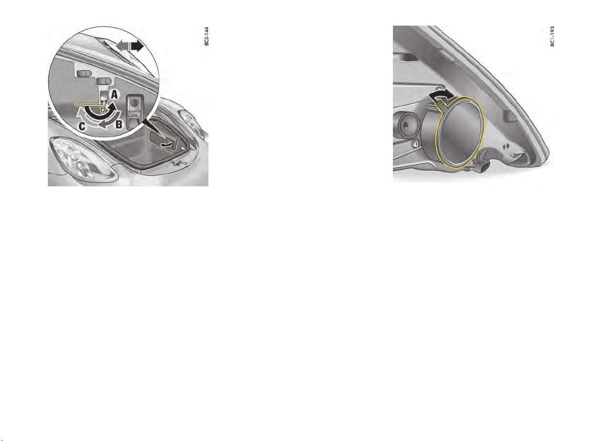
Minor Repairs 211
Removing headlights
1. Open front luggage compartment lid.
2. Remove the relevant toolbox.
3. Open up the cover for the headlight release
mechanism.
4. Place socket wrench (tool kit) on the unlocking
spindle.
The handle of the wrench should point
horizontally to the rear.
5. Turn wrench approx. 180° A. This unlocks the
headlight and pushes it forward slightly.
6. Turn socket wrench back until it is pointing
vertically downwards B and leave in position.
7. The headlight is now unlocked and can be
pulled forward out of the wing by lifting slightly.
8. Detach plug.
Installing headlights
1. Attach plug (clearly audible clicking sound).
2. Insert headlight into the guide rails and push
fully into the wing.
3. Push headlight to the rear and at the same
time turn the socket wrench until it points
horizontally to the rear C.
You should feel and hear the headlight locking
mechanism engage.
4. Close the cover for the headlight release
mechanism.
5. Attach tool box.
6. Check function of all bulbs.
f
Changing bulb for turn signal light
Opening the cover of the headlight housing
1. Remove the headlight.
f Please see the chapter “REMOVING
HEADLIGHTS” on page 211.
2. Remove the housing cover by pulling on
the tab (illustration).
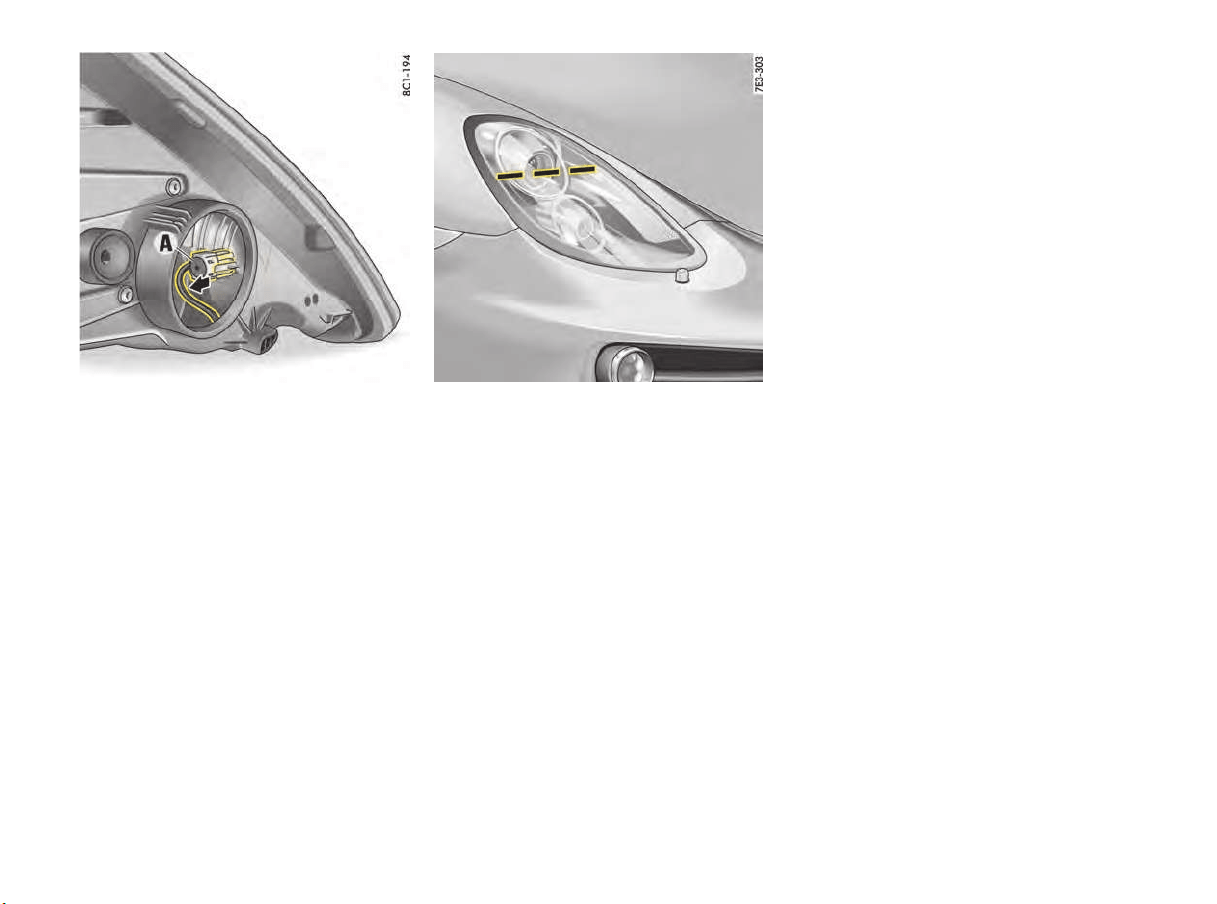
212 Minor Repairs
3. Remove the bulb holder A.
4. Replace defective bulb (bayonet lock).
5. Inser
t the bulb holder A into the guide and push
it in as far as it will go.
6. Close the housing cover.
7. Install the headlight and check operation of
bulb.
f Please see the chapter “INSTALLING
HEADLIGHTS” on page 211.
Headlight Adjustment
f Check tire pressure and adjust if necessary.
f Please see the chapter “TIRE PRESSURE FOR
COLD TIRES (68 °F/ 20 °C)” on page 221.
f Please see the chapter “REPLACING LIGHT-
EMITTING DIODES AND LONG-LIFE BULBS”
on page 210.
Adjustment
The adjustment is made with the vehicle ready to
drive and the fuel tank completely filled.
The driver's seat must be loaded by a person or a
165 lbs. (75 kg) weight and the tire pressures
must meet the prescribed values. After being
loaded, the car must be rolled a few meters so
that the suspension can settle.
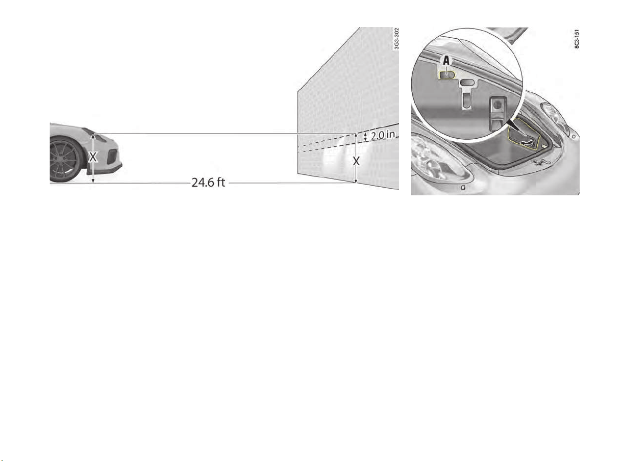
Minor Repairs 213
For checking the headlight adjustment, the
vertical position of the cutoff of the lowbeam (see
fig.) has to be projected on a vertical screen (wall)
in distance of 24.6 ft. (7.5 m) from the front lens
of the headlamp.The correct position of the cutoff
is 2.0 in. (5 cm) at 24.6 ft. or 7.5 m (0.4°) below
a horizontal line, x cm from ground to the center
of the headlamp lens.
Lateral adjustment of the headlights should be
carried out at a specialist workshop with an optical
adjustment unit.
Distance
Visual aim shall be performed at not less than
24.6 ft. (7.5 m) (this value is a rounded down
conversion from the 25-foot distance typical of
field aim using a screen). The 24.6 ft. (7.5 m)
distance is measured from the headlamp lens to
the viewing screen.
Floor
The surface upon which the vehicle rests is flat
and approximately level.
Screen
The screen upon which headlamp beams are
projected is perpendicular to the floor and the
vehicle's longitudinal axis, flat, uniformly light in
color, unobstructed, and wide and high enough to
accommodate the vehicle beam patterns to be
aimed.
The screen should be wide enough to provide at
least 3.3 ft. (1 m) of space outboard of the
vehicle's headlamp spacing.
A - Height adjustment
Height adjustment
1. Switch ignition on.
2. Switch on low beam.
3. Open front luggage compartment lid.
4. Remove the relevant toolbox.
5. Open up the cover A for the adjusting screw.
6. Place allen key (5 mm) on adjusting screw.
7. Adjust low beam in the corresponding
direction.
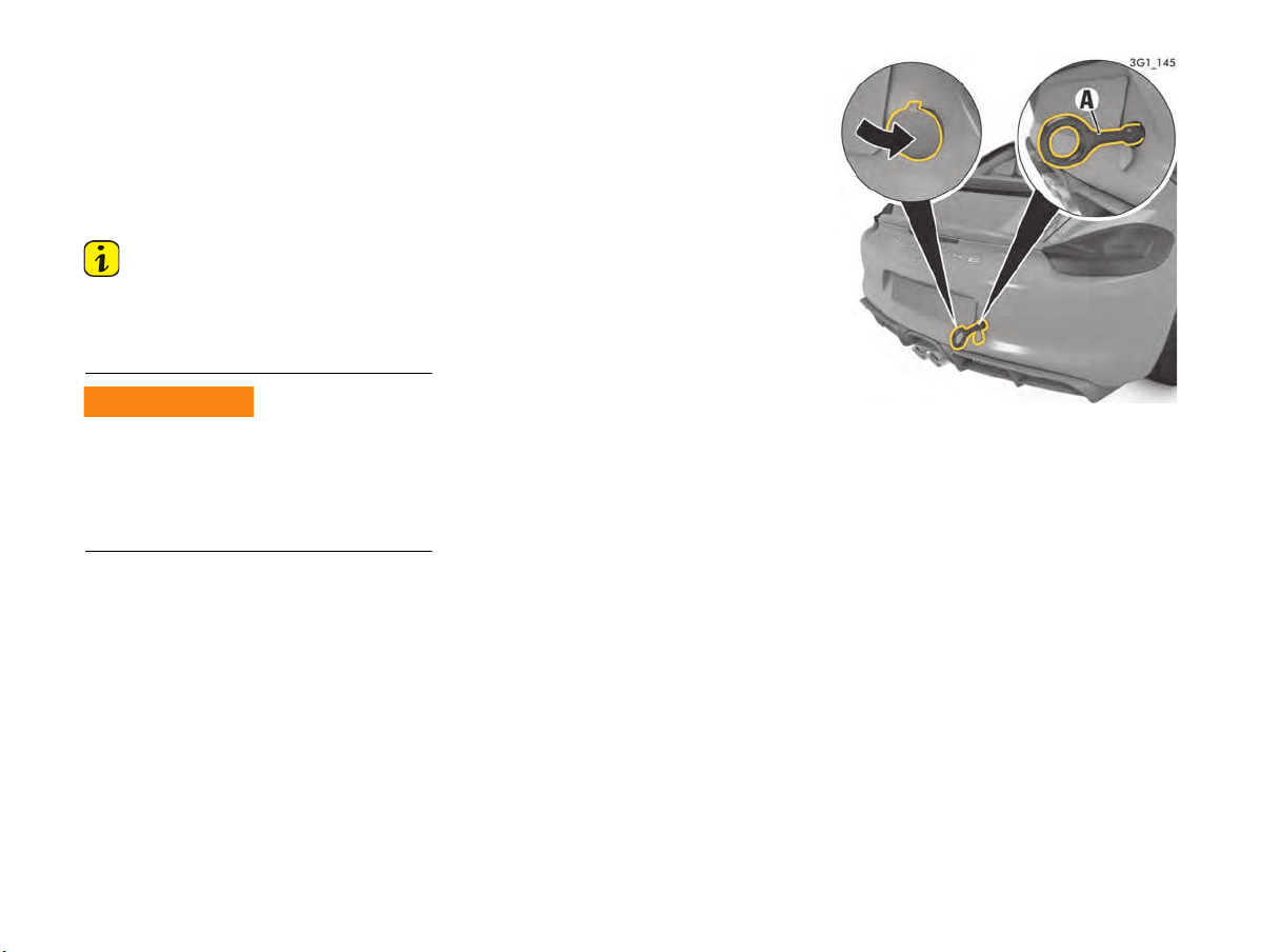
214 Minor Repairs
Towing
Certain state statutes and local ordinances
prohibit towing with a chain, rope or even a tow
bar. In addition, damage to your vehicle may result
from improper precedures. Consult your
authorized Porsche dealer for details.
Flat bed towing is the preferred type of towing to
be used on Porsche vehicles.
Information
f Always observe the laws governing towing and
tow-starting.
f Exercise extreme care when your vehicle is
being towed.
No power assistance is available on the towed
vehicle when its engine is not running. Greater
force is therefore required when braking and
steering.
f Exercise extreme care when your vehicle is
being towed.
When the engine is not running, adequate
lubrication of the transmission is not warrantied.
Observe the following points to avoid damage to
the transmission.
Towing a vehicle with manual transmission
on all four wheels:
f Put the gearshift lever in neutral.
f The vehicle must always roll on all four wheels
when towed.
The ignition must be switched on so that the
brake lights and turn signal lights operate.
Towing a vehicle with manual transmission
on one axle:
f Switch ignition off.
f Put the gearshift lever in neutral.
f Make sure that the vehicle is adequately
illuminated.
f Do not exceed a maximum speed of 30 mph
(50 km/h).
Maximum towing distance 30 miles (50 km).
If towing distances are greater, the vehicle
must be transported with a car transporter or
on a trailer.
Pulling out a vehicle stuck in snow,
sand, etc.
f Always pull out the stuck vehicle with the
greatest care.
f Do not pull out the vehicle abruptly or at an
angle.
f If possible, pull the vehicle out backwards in
its own tracks.
Rear towing lug
Fitting the towing lug
1. Press the lower edge of the appropriate plastic
cover into the bumper until the cover
disengages.
2. Pull cover out of the bumper and let it hang by
its thread.
3. Screw in towing lug A as far as it will go
(left-hand thread) and tighten hand-tight.
Towed vehicle hazards
WARNING
h
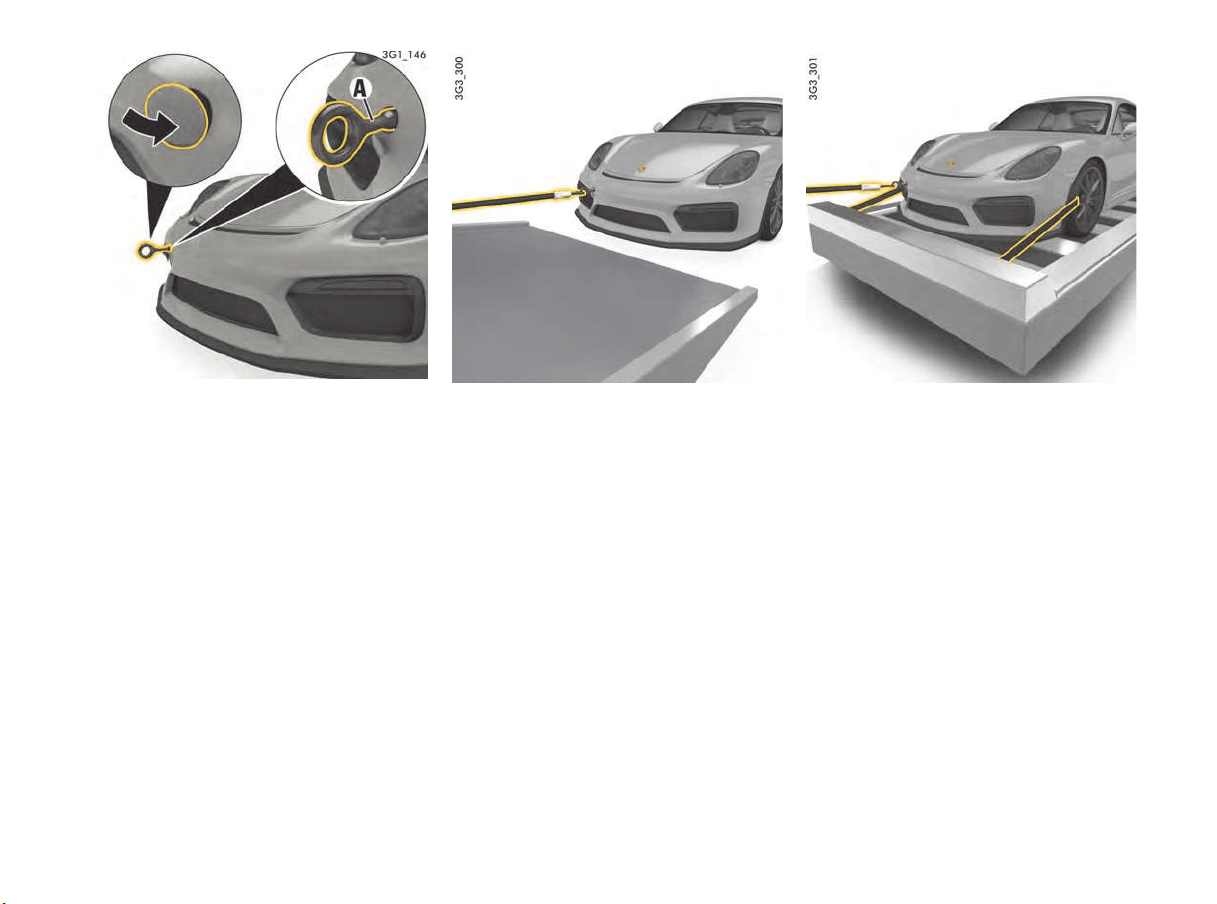
Minor Repairs 215
Front towing lug
Removing the towing lug
1. Unscrew the towing lug A.
2. Insert plastic cover at the lower edge of the
opening.
3. Fold the cover up and press on its upper edge
to engage it in the bumper.
4. Store the towing lug in the tool box.
Pulling vehicle onto flat bed
1. Position wooden ramps at the base of the flat
bed to reduce the angle of the pull.
2. Reel in the hoist cable and check the underside
of the vehicle for any interference.
Tying down vehicle on flat bed
1. Carefully feed towing straps through the
opening in the rear wheels.
Make sure metal parts of straps do not
damage rim.
Make sure the strap is flat over the rim bead.
Make sure brake backing plate is not
damaged.
2. Secure straps to rear of flat bed.
3. Reel in hoist cable only far enough to tension
tie-down straps.
Transporting the vehicle on car trains,
ferries and car transporters
f Tie the vehicle down only at its wheels.
f Deactivate interior surveillance and the
inclination sensor.
f Please see the chapter “ALARM SYSTEM AND
PASSENGER COMPARTMENT MONITORING”
on page 159.
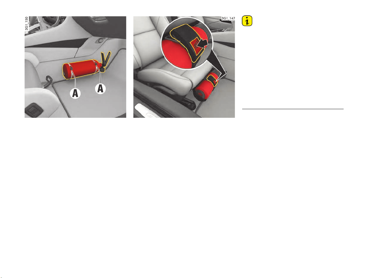
216 Minor Repairs
Fire extinguisher
Vehicles with Club Sport package
In vehicles with a fire extinguisher, the extinguisher
is attached in the passenger’s footwell.
f To remove the fire extinguisher in the event of
an emergency, hold the extinguisher with one
hand and release both locking elements A on
the fire extinguisher holder with the other hand.
Vehicles without Club Sport package
In cars with a fire extinguisher, the extinguisher is
located under the front passenger seat.
f To remove the fire extinguisher in case of an
emergency, hold the extinguisher with one
hand and press the button PRESS on the fire
extinguisher holder with the other hand
(arrow).
Information
f Check the final inspection date on the fire
extinguisher. If the fire extinguisher is used
after its inspection interval has elapsed, it may
not work properly.
f Always read the operating instructions on the
fire extinguisher.
f Observe the fire extinguisher manufacturer’s
safety instructions on the label at the fire
extinguisher handle.
f The fire extinguisher should be checked to
ensure correct operation by a specialist
workshop every 1-2 years.
f Have the fire extinguisher refilled after use.

Tire Pressure and Technical Data 217
Tire Pressure and Technical Data
Vehicle Identification Data ............................218
Engine Data................................................219
Wheels, Tires..............................................220
Tire Pressure for Cold Tires (68 °F/ 20 °C) ...221
Weights......................................................222
Filling Capacities .........................................223
Driving Performance....................................224
Chassis Setup.............................................224
Engine Diagram at Full Load.........................225
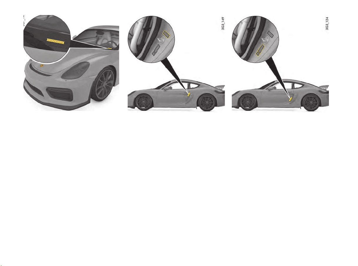
218 Tire Pressure and Technical Data
Vehicle identification number
Vehicle Identification Data
When ordering spare parts or making inquiries,
please always quote the vehicle identification
number.
Vehicle identification number
You will find the vehicle identification number at
the bottom left behind the windshield in the
direction of travel and under the front passenger´s
seat.
Identification plate
Safety compliance sticker
The safety compliance sticker is your assurance
that your new Porsche complies with all applicable
Federal Motor Vehicle Safety Standards which
were in effect at the time the vehicle was
manufactured.
The sticker also shows the month and year of
production and the vehicle identification number of
your car (perforations) as well as the Gross
Vehicle Weight Rating and the Gross Axle Weight
Rating.
Tire pressure plate
Tire pressure plate
The tire-pressure plate is attached to the B-pillar in
the driver´s door sill area.
Vehicle data carrier
You will find the vehicle data carrier in the
“Maintenance” booklet.
It contains all important data about your vehicle.
This data carrier cannot be re-ordered if it is lost
or damaged.

Tire Pressure and Technical Data 219
Engine Data
Cayman GT4
Number of cylinders 6
Displacement 231.9 cu. in. (3,800 cm
3
)
Max. engine output
as per 80/1269/EEC
283 kW (385 hp)
At engine speed 7,400 rpm
Max. torque
as per 80/1269/EEC
420 Nm (309,7 ftlb.)
At engine speed 4,750 – 6,000 rpm
Maximum permitted engine speed 7,800 rpm

220 Tire Pressure and Technical Data
Wheels, Tires
f Approval of tire and wheel sizes is granted based on extensive testing. Your authorized Porsche dealer will be pleased to advise you about the current
approval status.
By fitting tires that have been approved by Porsche, you can be sure that you have the best possible tires for your Porsche.
The load capacity coefficient (e.g. “92”) and maximum speed code letter (e.g. “Y”) for permitted top speed are minimum requirements.
When fitting new tires or changing tires: Please see chapter “TIRES AND WHEELS” on page 186.
f Snow chain clearance can only be warrantied with the tires marked
1)
. Snow chains can only be fitted on the rear wheels. Observe state- or province-
specific laws regarding maximum speeds with fitted snow chains. Only use Porsche approved fine-link cross-type or edge chains.
FA = front axle, RA = rear axle
Installation of sizes not authorized by Porsche
may impair driving stability and could result in loss
of control of the vehicle.
Before mounting new tires check with your
authorized Porsche dealer for a current list of
approved tires.
Cayman GT4
20-inch wheel FA / RA 8,5J x 20, RO 61 / 11J x 20, RO 50
Summer tires FA / RA 245/35 ZR20 (91Y) / 295/30 ZR20 (101Y) XL
Snow tires FA / RA 245/35 R20 91V M+S / 295/30 R20 97V M+S
20-inch wheel FA / RA 8,5J x 20, RO 57 / 10J x 20, RO 50
1)
Snow tires FA / RA 235/35 R20 92V M+S / 275/30 R20 97V M+S
1)
Improper tire size
DANGER
h

Tire Pressure and Technical Data 221
Tire Pressure for Cold Tires (68 °F/ 20 °C)
The standard and comfort tire pressure applies only to the tire makes and types approved by Porsche.
f Please see chapter “TIRE PRESSURE MENU (TIRE PRESSURE MONITORING SYSTEM, TPMS)” on page 86.
Standard tire pressure for summer tires
FA = front axle, RA = rear axle
Standard tire pressure for snow tires
FA = front axle, RA = rear axle
20-inch wheels
FA RA
Cayman GT4
29 psi/
2.0 bar/
200 kPa
33 psi/
2.3 bar/
233 kPa
20-inch wheels
FA RA
Cayman GT4
36 psi/
2.5 bar/
250 kPa
36 psi/
2.5 bar/
250 kPa

222 Tire Pressure and Technical Data
Weights
1)
Curb weight includes 165 lbs. (75 kg) driver and baggage share.
2)
The maximum vehicle weight and maximum axle loads must not be exceeded.
Notice: If additional accessories are installed, the maximum load will be correspondingly less.
Cayman GT4
Empty weight (depending on equipment)
per DIN 70020
2955 lbs. to 3109 lbs.
(1,340 kg to 1,410 kg)
Empty weight (depending on equipment)
per 70/156/EEC
1)
3120 lbs. to 3274 lbs.
(1,415 kg to 1,485 kg)
Maximum axle load, front
2)
1731 lbs. (785 kg)
Maximum axle load, rear
2)
1995 lbs. (905 kg)
Maximum Gross vehicle weight
2)
3616 lbs. (1,640 kg)

Tire Pressure and Technical Data 223
Filling Capacities
Only use fluids and fuels approved by Porsche. Your authorized Porsche dealer will be pleased to advise you.
Engine oil change quantity with oil filter Approx. 1.98 US gallons (7.5 liters)
Engine oil specification
Porsche A40; SAE 0W - 40, SAE 5W - 40, SAE 5W - 50
f Please see chapter “TOPPING UP ENGINE OIL” on page 166.
Fuel tank
Approx. 14.26 US gallons (54 liters) including approx. 2.64 US gallons (10 liters) reserve
optional approx. 16.91 US gallons (64 liters) including approx. 2.64 US gallons (10 liters) reserve
Fuel octane rating
The engine is designed to provide optimum performance and fuel consumption if unleaded premium
fuel with 98 RON/88 MON (93 CLC or AKI) is used.
f Please see chapter “FUEL” on page 171.
Windshield/headlight washer system Approx. 1.59 US gallons (6 liters)

224 Tire Pressure and Technical Data
Driving Performance
The specifications refer to a vehicle with DIN curb weight without performance-reducing additional equipment (e.g. special tires).
Dimensions
Chassis Setup
The anti-roll bars can be individually adjusted at the front and rear axles. We recommend using the standard setting including on the race circuit.
When used on public roads, the chassis must be in the standard setting.
f Important notes on chassis setup are included in the separate brochure “DRIVING ON THE RACE CIRCUIT”.
Cayman GT4
Maximum speed 183,3 mph (295 km/h)
Acceleration 0 to 100 km/h (62 mph) 4.4 seconds
Cayman GT4
Length 174.7 in. (4,438 mm)
Width without exterior mirrors 71.5 in. (1,817 mm)
Width with exterior mirrors 77.9 in. (1,978 mm)
Height at DIN curb weight 49.9 in. (1,266 mm)
Wheelbase 97.8 in. (2,484 mm)
Ground clearance at maximum gross weight 4.1 in. (105 mm)
Turning circle 37.4 ft. (11,4 m)
Cayman GT4
Driving on public roads and on race circuits
Front axle overall toe-in +2’
±2’
Rear axle toe-in per wheel +10’ ±2’
Front axle camber -1°30’ ±3’
Rear axle camber -1°30’ ±5’
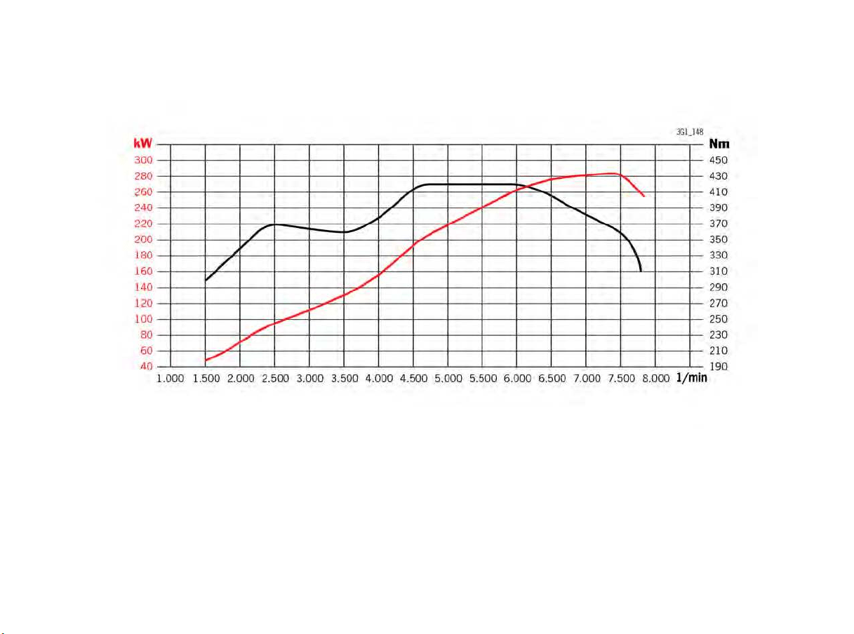
Tire Pressure and Technical Data 225
Engine Diagram at Full Load

226 Index
Index
A
A/C button
Air-conditioning system.................................51, 55
A/C MAX button
Air-conditioning system.................................52, 56
ABD (automatic brake differential)
Functional description.......................................136
ABS (Anti-lock Brake System)
Functional description.......................................138
Acoustic signals ............................................................77
Adapting fuel gauge.....................................................102
Adaptive light system, driving light assistant ....................64
Adhesive foils, care instructions....................................178
Adjusting seat position ...................................................31
Aftermarket Alarms......................................................127
Air cleaner, maintenance instructions ............................186
Air conditioning
Manual air conditioning .......................................51
Setting air quantity .............................................53
Air distribution...................................................50, 54, 58
Air vents
Adjusting ...........................................................59
Opening/closing.................................................59
Airbag
Airbag warning light on the tachometer ................39
Automatic deactivation of the passenger airbag....38
Care instructions..............................................179
Disposal ............................................................37
Function ............................................................37
Functional description.........................................35
Installation location.............................................35
Passenger airbag warning light............................39
Air-conditioning compressor
Information on air-conditioning compressor ....51, 55
Air-conditioning system
Automatic load switch-off ..............................51, 55
Defrosting windshield....................................49, 52
Extended ventilation panel...................................58
Information on air-conditioning compressor ....51, 55
Manual air conditioning .......................................49
Setting air distribution ..................................54, 58
Setting air quantity .......................................50, 57
Setting automatic air-recirculation mode...............57
Setting temperature ...............................50, 53, 57
Switching A/C MAX mode on/off ...................52, 56
Switching A/C mode on/off...........................51, 55
Switching air-conditioning compressor on/off .51, 55
Switching air-recirculation mode on
and off.................................................. 49, 53, 56
SYNC (MONO) mode .......................................... 55
Temperature sensor........................................... 54
Air-recirculation button
Air-conditioning system .......................... 49, 53, 56
Alarm button................................................................. 18
Alarm system
Avoiding false alarms....................................... 160
Functional description ...................................... 159
Persons/animals remaining in the locked vehicle 159
Switching off ................................................... 159
Switching off interior surveillance and inclination
sensor ............................................................ 159
Switching on ................................................... 159
Alcantara
®
, care instructions ....................................... 180
Alloy wheels
Care instructions ............................................. 178
Inscription....................................................... 195
Alternator
Vehicle electrical system warning........................ 77
Aluminum rims
Care instructions ............................................. 178
Inscription....................................................... 195
Ambient lighting ............................................................ 68
Antifreeze
in coolant........................................................ 184
in washer fluid ................................................. 167
Anti-lock brake system (ABS)
Functional description ...................................... 138
Anti-slip control (ASR)
Functional description ...................................... 136
Armrest
Opening oddments tray.................................... 144
Ashtray
Emptying ........................................................ 146
Opening.......................................................... 146
ASR (Anti-slip control)
Functional description ...................................... 136
Audio
Tips................................................................ 126
Audio interface, installation position.............................. 128
AUTO (light switch)........................................................ 64
Driving light assistant......................................... 64
Automatic brake differential (ABD)
Functional description ...................................... 136
Automatic Coming Home lights, courtesy lighting
Entry function ....................................................65
Welcome Home function.....................................65
Automatic speed control (cruise control)
Accelerating .................................................... 125
Decelerating....................................................125
Functional description.......................................124
Interrupting operation.......................................125
Storing speed.................................................. 125
Switching off ...................................................126
Switching on....................................................125
AUX interface, installation position ................................ 128
B
Baby seat
Installing with Top Tether system .........................43
Prescribed installation direction
(depending on weight of child).............................40
Top Tether restraint system ................................43
Battery
Care ............................................................... 206
Changing in car key..........................................209
Charging ......................................................... 208
Emergency starting with jumper cables..............207
General information.......................................... 205
Installation position...........................................205
Procedure after connection...............................207
Replacing ........................................................207
Vehicle electrical system warning ........................77
Winter driving ..................................................206
Before driving off ............................................................5
Belts
Care instructions..............................................180
Fastening ..........................................................34
Opening belt buckle ...........................................35
Safety-belt pretensioners, functional description ...34
Warning light on the tachometer..........................34
Brake booster.............................................................123
Brake disks..................................................................... 3
Brake fluid ...................................................................... 3
Changing.........................................................185
Warning light on speedometer........................... 185
Brake pads ..................................................................... 3
Breaking in new brake pads ..................................7
Warning message, brakes ................................ 123
Brake pedal ................................................................122

Index 227
Brake wear
Warning message.............................................123
Brakes
Applying/releasing parking brake.......................120
Brake pad warning message .............................123
Brake pedal .....................................................122
Brake wear warning message ...........................123
Break in new brake pads.......................................7
Footbrake........................................................121
General information ..............................................5
Test stand ...............................................164, 183
Break in hints ..................................................................7
Breaking in
Engine.................................................................7
Engine oil and fuel consumption during
break-in period.....................................................7
Hints ...................................................................7
New brake pads and brake disks...........................7
New tires.............................................................7
Brief overview
Opening and locking the vehicle from outside .......20
Bulbs
Overview .........................................................210
C
Car care
Airbags ...........................................................179
Alcantara
®
.......................................................180
Alloy wheels.....................................................178
Fabric linings ...................................................180
Headlights, plastic components, adhesive foils ...178
Leather ...........................................................179
Leather care for seats with seat ventilation.........179
Paint ...............................................................176
Safety-belts .....................................................180
Seals ..............................................................178
Underbody protection.......................................177
Use of high-pressure cleaning equipment ...........175
Washing the vehicle, instructions .......................175
Wheel attachment faces....................................198
Wheel bolts......................................................199
Windows..........................................................177
Car key (remote control)
Changing battery..............................................209
Locking vehicle door ..........................................22
Unlocking vehicle door........................................21
Car Telephone .............................................................127
Care instructions
Airbags ...........................................................179
Alcantara
®
.......................................................180
Alloy wheels.....................................................178
Car washing .................................................... 175
Carpet ............................................................ 179
Fabric linings................................................... 180
Headlights, plastic components, adhesive foils... 178
Leather........................................................... 179
Leather care for seats with seat ventilation ........ 179
Mats............................................................... 179
Paint............................................................... 176
Safety-belts ..................................................... 180
Seals .............................................................. 178
Underbody protection ...................................... 177
Use of high-pressure cleaning equipment ........... 175
Wheel attachment faces ................................... 198
Wheel bolts ..................................................... 199
Windows ......................................................... 177
Carpet, care instructions ............................................. 179
Catalytic converter ...................................................... 169
Emission control (Check Engine) ......................... 77
Center armrest
Opening oddments tray .................................... 144
Central locking.............................................................. 23
Driver’s door emergency operation,
Passenger’s door emergency operation............... 28
Locking vehicle door with car key
(remote control)................................................. 22
Opening and locking vehicle door from inside....... 23
Unlocking vehicle door with car key
(remote control)................................................. 21
Central locking system
Functional description ........................................ 19
Centre console ............................................................. 14
Changing car key (remote control) battery..................... 209
Changing wheels......................................................... 196
Chassis control systems
Overview (PSM, PASM, PTV) ............................. 134
Chassis number, position............................................. 218
Chassis setup ............................................................. 224
Functional description ...................................... 139
Selecting......................................................... 139
Check Engine (emission control)
Functional description ........................................ 77
Warning light ..................................................... 77
Checking pressure ...................................................... 198
Child restraint equipment
Prescribed installation direction .......................... 39
Child seat
Prescribed installation direction .......................... 39
Prescribed installation direction
(depending on weight of child) ............................ 40
Chrono......................................................................... 95
Cigarette lighter.......................................................... 146
Closing .........................................................................25
Locking vehicle door from inside .........................23
Persons/animals remaining in the vehicle .............22
Vehicle door with car key (remote control)............22
Closing luggage compartment lid....................................25
Closing luggage compartment lids ..................................25
Clutch
Manual transmission.........................................132
Cockpit.........................................................................11
Adjusting lighting................................................66
Cooling system, temperature gauge ..................100
Engine oil temperature gauge............................101
Fuel gauge.........................................................76
Odometer..........................................................76
Speedometer.....................................................76
Tachometer .......................................................76
Warning and indicator lights, overview..................74
Compressor
Tire pressure ...................................................148
Control systems
Overview (PSM, PASM, PTV) ..............................134
Coolant
Checking level..................................................184
Topping up.......................................................184
Cooling system
Warning on multi-function display .......................100
Cornering light
Dynamic ............................................................65
Courtesy lighting, Entry function .....................................65
Crankcase ventilation...................................................169
Cruise control
Accelerating ....................................................125
Decelerating ....................................................125
Functional description.......................................124
Interrupting operation .......................................125
Storing speed ..................................................125
Switching off....................................................126
Switching on ....................................................125
Cupholder ...................................................................145
D
Data carrier for vehicle data .........................................218
Daytime driving lights.....................................................64
Defrosting windshield...............................................49, 52
Air-conditioning system.................................49, 52
Diagnostic socket........................................................118
Diagrams....................................................................225
Digital speedometer ......................................................76
Dimensions .................................................................224

228 Index
Dimming
Adjusting brightness of instrument lighting ...........66
Adjusting brightness of interior lighting ................67
Direction indicator, stalk.................................................66
Displacement, Technical data .......................................219
Door
Locking if persons/animals are remaining
in vehicle...........................................................22
Locking with car key (remote control) ..................22
Malfunctions when opening and closing................26
Opening and locking from inside..........................23
Unlocking with car key (remote control) ...............21
Door emergency locking ................................................28
Door locking, automatic.................................................22
Door opening in an emergency situation ..........................22
Drinks holder ..............................................................145
Drive
The vehicle cannot be unlocked...........................26
Driver’s door emergency locking.....................................28
Driving
In Sport mode......................................................3
On the race circuit ...............................................3
Driving light assistant
Daytime driving lights .........................................64
Dynamic cornering light ......................................65
Low beam .........................................................64
Switching on......................................................64
Driving off
Automatic parking brake release upon
driving off........................................................121
Driving performance, Technical data .............................224
DVD
Installation location...........................................128
Navigation .......................................................128
Player .............................................................128
Dynamic cornering light .................................................65
Dynamic Engine Mounting (PADM) .................................140
E
Electric parking brake
Automatic parking brake release upon
driving off........................................................120
Emergency braking function..............................120
Operating ........................................................120
Releasing ........................................................120
Testing on brake test stand.......................164, 183
Warning light....................................................120
Electrical System
Emergency unlocking, front luggage
compartment lid ..............................................204
Emergency flasher.........................................................67
Emergency key....................................................... 19, 28
Emergency operation
Filler flap......................................................... 172
of ignition key/control unit in ignition lock ............ 27
of luggage compartment lid ............................... 26
of tailgate ......................................................... 26
Emergency release
Front luggage compartment lid......................... 204
Emergency starting for flat battery ............................... 207
Emergency starting with jumper cables......................... 207
Emission control (Check Engine)
Functional description ........................................ 77
Engine
Break in hints ...................................................... 7
Checking oil level............................................. 165
Cooling system ............................................... 100
Oil-level gauge................................................... 82
Starting .......................................................... 119
Stopping......................................................... 120
Technical data ................................................. 219
Topping up oil.................................................. 166
Engine drag torque control (MSR)
Functional description ...................................... 136
Engine oil ................................................................... 165
Change quantity .............................................. 223
Checking level................................................. 165
Consumption................................................... 219
Engine oil pressure .......................................... 109
Filler opening................................................... 167
General information ................................. 165, 166
Oil-level warning on the multi-function display ..... 165
Pressure gauge ............................................... 101
Temperature gauge ......................................... 101
Entry function, courtesy lighting when entering the
vehicle ......................................................................... 65
Error messages
Overview......................................................... 109
Exhaust pipes ................................................................. 4
Exhaust system
Sport.............................................................. 141
Exterior mirror
Adjusting........................................................... 44
Exterior mirror heating
Switching on/off ................................................ 59
External audio source, interface................................... 128
F
Fabric linings (care instructions) ................................... 180
Fault reporting
Overview......................................................... 109
Faults
Emergency operation of ignition key/control
unit in ignition lock .............................................27
Emergency operation of powerlift tailgate ............26
Emergency operation of the filler flap.................172
Power windows..................................................62
When opening and closing ..................................26
Filler flap, emergency operation....................................172
Filling capacities
Coolant ...........................................................223
Engine oil ........................................................223
Fuel ................................................................223
Overview of fluids and fuels...............................223
Washer fluid.....................................................223
Filter
Air cleaner, maintenance instructions.................186
Particle filter, maintenance instructions..............186
Fire extinguisher, storage location ................................216
Floor mats, care instructions........................................179
Fluids and fuels
Coolant ...........................................................223
Engine oil ........................................................223
Fuel ................................................................223
Washer fluid.....................................................223
Folding the seat backrest forward.............................32, 33
Footbrake
Safety notes ....................................................121
Front luggage compartment lid
Emergency release ..........................................204
Fuel
Economy.........................................................170
Evaporation control ..........................................174
Fuel can ..........................................................173
Fuel gauge ........................................................76
Fuel reserve warning ....................................76, 79
Fuels containing ethanol ...................................173
Octane rating...................................................171
Portable fuel containers........................................4
Quality.............................................................171
Recommendation .............................................173
Refueling .........................................................171
Tank capacity...................................................223
Fuel can......................................................................173
Fuel container .............................................................173
Fuel containers, portable..................................................4
Fuel gauge....................................................................76
Fuel level indicator
Fuel gauge ........................................................76
Fuel reserve................................................................172
Fuse, changing electric fuses .......................................201

Index 229
G
Garage door opener
Deleting programed signals ..............................155
Functional description.......................................154
Operating ........................................................155
Programing signal (changeable code system).....156
Programing signal (fixed code system)...............155
Gear display
Manual transmission.........................................133
PDK transmission/manual transmission................76
Gear shift assist ............................................................97
G-forces display.............................................................98
Glove box
Locking ...........................................................143
Opening...........................................................143
Ground clearance ............................................................4
H
Handbrake (electric parking brake)
Operating ........................................................120
Releasing ........................................................121
Head restraints..............................................................31
Headlights
Adjusting .........................................................212
Care instructions..............................................178
Installing..........................................................211
Notes..............................................................210
Operating washer system ...................................71
Removing ........................................................211
Heated rear window
Switching on/off.................................................59
Heating and ventilation
Setting air distribution ........................................50
High-beam headlight ......................................................66
Stalk .................................................................66
High-pressure cleaning equipment
Instructions for use ..........................................175
HomeLink
®
(garage door opener)
Deleting programed signals ..............................155
Functional description.......................................154
Operating ........................................................155
Programing signal (changeable code system).....156
Programing signal (fixed code system)...............155
Hot exhaust pipes............................................................4
I
Identification number, position ......................................218
Ignition lock
Emergency operation of the key ..........................27
Functional description.......................................118
Immobilizer
Functional description ...................................... 160
Switching on/off .............................................. 160
Inclination sensor
Function indication ........................................... 160
Switching off with vehicle key (remote control) ... 159
Information messages
Overview......................................................... 109
Instrument cluster
Adjusting lighting ............................................... 66
Cooling system, temperature gauge.................. 100
Engine oil temperature gauge ........................... 101
Fuel gauge ........................................................ 76
Odometer ......................................................... 76
Speedometer .................................................... 76
Tachometer....................................................... 76
Warning and indicator lights, overview ................. 74
Instrument lighting......................................................... 66
Instrument panel ........................................................... 12
Adjusting lighting ............................................... 66
Cooling system, temperature gauge.................. 100
Engine oil temperature gauge ........................... 101
Fuel gauge ........................................................ 76
Odometer ......................................................... 76
Speedometer .................................................... 76
Tachometer....................................................... 76
Warning and indicator lights, overview ................. 74
Interior lighting
Ambient lighting................................................. 68
Interior lights ..................................................... 67
Orientation lighting............................................. 68
Interior lights ................................................................ 67
Interior mirror
Adjusting........................................................... 45
Switching automatic anti-dazzle function on/off .... 46
Interior surveillance ..................................................... 160
Switching off with vehicle key (remote control) ... 159
iPod
®
interface, installation position ............................. 128
J
Jump-lead starting, external power supply..................... 207
K
Key
Changing battery ............................................. 209
Emergency operation, ignition lock...................... 27
Locking vehicle door.......................................... 22
Removing emergency key............................. 19, 28
Replacement keys ............................................. 18
Unlocking vehicle door ....................................... 21
Keys.............................................................................18
L
LATCH system
Prescribed installation direction of child seat
(depending on weight of child) .............................40
Lateral acceleration forces
Display ..............................................................98
Leather, care instructions.............................................179
Seats with seat ventilation.................................179
Lids
Emergency unlocking, front luggage
compartment lid...............................................204
Light
Headlight flasher ................................................66
Switching on courtesy lighting when entering the
vehicle ..............................................................65
Switching on Welcome Home function..................65
Light switch
AUTO function....................................................64
Overview ...........................................................64
Lights
Bulb chart........................................................210
Care instructions..............................................178
Replacing bulbs................................................210
Switching interior lights on/off automatically.........68
Switching on when entering the vehicle ................65
Switching on when leaving the vehicle..................65
Loading information .....................................................151
Locking
Locking vehicle door from inside .........................23
Locking vehicle door with car key
(remote control) .................................................22
Persons/animals remaining in the vehicle .............22
Vehicle door with car key (remote control)............22
Longitudinal acceleration forces
Display ..............................................................98
Luggage compartment...................................................29
Opening.............................................................25
Overview .................................................148, 150
Luggage cover............................................................150
M
Maintenance work
Adding washer fluid ..........................................167
Changing Air Cleaner ........................................186
Changing Particle Filter.....................................186
Checking engine oil level...................................165
Checking the Coolant Level and Adding Coolant..184
Notes on maintenance..............................162, 182

230 Index
Topping up engine oil........................................166
Malfunctions
Emergency operation of ignition key in ignition
lock ..................................................................27
Emergency operation of luggage compartment
lid .....................................................................26
Emergency operation of tailgate..........................26
Power windows..................................................62
Storing end position of the windows ....................62
When opening and closing ..................................26
Manual air conditioning ..................................................51
Maximum permitted engine speed
Manual transmission.........................................133
Minor repairs
In the event of a flat tire....................................199
Mirrors
Adjusting exterior mirrors ...................................44
Exterior mirror heating .......................................59
Switching automatic anti-dazzle function on and
off ....................................................................46
Vanity mirror......................................................47
Motion sensor (interior surveillance)
Switching off with vehicle key (remote control)....159
Multi-function display
Activating functions, opening menus and viewing
options..............................................................79
Browsing through long lists .................................79
Checking oil level ...............................................82
Display areas.....................................................79
Menu overview...................................................80
Operating navigation system...............................85
Operating principle.............................................78
Performance display ..........................................98
Retrieving vehicle information..............................81
Selecting a radio station .....................................83
Sport Chrono.....................................................96
Tire Pressure Monitoring System.........................86
Tire pressure warnings .................................90, 93
Trip information..................................................86
Using the phone.................................................84
Warning messages...........................................109
N
Navigation system.......................................................128
Using via multi-function display ............................85
O
Octane rating ..............................................................173
Octane rating, petrol....................................................171
Odometer
Display ............................................................. 76
Resetting .......................................................... 76
Off delay
Switching on ..................................................... 65
Oil ............................................................................. 165
Change quantity .............................................. 223
Checking level........................................... 82, 165
Consumption....................................................... 7
General information ................................. 165, 166
Level gauge ...................................................... 82
Oil pressure .................................................... 109
Oil-level warning on the multi-function display ..... 165
Pressure gauge, oil pressure ............................ 101
Temperature gauge ......................................... 101
Topping up...................................................... 166
On-board computer
Measuring oil level ............................................. 82
Menu overview .................................................. 80
Multi-function display.......................................... 78
Operating principle ............................................ 78
Performance display .......................................... 98
Tire Pressure Monitoring System ........................ 86
Opening and closing
Brief overview ................................................... 20
Locking vehicle door with car key
(remote control)................................................. 22
Opening and locking vehicle door from inside ...... 23
Unlocking vehicle door with car key
(remote control)................................................. 21
Opening and locking
The vehicle cannot be unlocked .......................... 26
Operating in other countries ........................................ 170
Orientation lighting ........................................................ 68
Oxygen sensor ........................................................... 169
P
PADM, Dynamic Engine Mounting ................................. 140
Paint
Care instructions ............................................. 176
Polishing......................................................... 176
Preserving ...................................................... 176
Removing spots and stains............................... 176
Repairing damage ........................................... 176
Panic button ................................................................. 18
Parking
Applying the parking brake ............................... 120
Locking the vehicle ............................................ 22
Parking brake
Automatic parking brake release upon driving
off .................................................................. 121
Operating ........................................................120
Releasing ........................................................120
Testing on brake test stand.......................164, 183
Particle filter, maintenance instructions .........................186
PASM (Porsche Active Suspension Management)
Functional description.......................................139
Overview .........................................................134
Selecting chassis setup....................................139
Warning message on the multi-function display ...140
PASS AIR BAG OFF
Warning light in the center console ......................39
Passenger airbag
Automatic deactivation of the passenger airbag ...38
Warning light in the center console ......................39
Passenger mirror
Adjusting ...........................................................44
Passenger’s door emergency locking, Emergency
operation
Driver’s door, Passenger’s door...........................28
PCCB (Porsche Ceramic Composite Brake)
General information..........................................4, 5
PCM (Porsche Communication Management) .................128
Performance display
Power ...............................................................98
Torque...............................................................98
Performance tests on roller-type test stands..........164, 183
Performance, Technical data ........................................219
Petrol
Fuel gauge ........................................................76
Fuel reserve warning ....................................76, 79
Octane rating...................................................171
Portable fuel container .....................................173
Portable fuel containers........................................4
Quality.............................................................171
Refueling .........................................................171
Tank capacity...................................................223
Plastic components, care instructions...........................178
Porsche Active Suspension Management (PASM)
Functional description.......................................139
Overview .........................................................134
Warning message on the multi-function display ...140
Porsche Ceramic Composite Brake (PCCB)
General information..........................................4, 5
Porsche Communication Management (PCM) .................128
Porsche Dynamic Light System (PDLS)............................65
Porsche Entry & Drive
Inclination sensor .............................................160
Interior surveillance ..........................................160
Porsche Stability Management (PSM)
Functional description.......................................135
Multi-function light in the tachometer..................138

Index 231
Overview .........................................................134
Switching off....................................................136
Porsche Torque Vectoring (PTV)
Functional description.......................................140
Overview .........................................................134
Portable fuel container .................................................173
Power
Display on the multi-function display.....................98
Power Steering ...........................................................186
Power windows
Adjusting after connecting battery .......................62
Malfunctions ......................................................62
Opening/closing windows with switch ..................61
Overview of driver’s door control panel ................61
Overview of passenger’s door control panel .........61
Storing end position ...........................................62
Pressure
Tires (bar/psi)..................................................221
Protection against towing (inclination sensor)
Switching off with vehicle key (remote control)....159
PSM (Porsche Stability Management)
Functional description.......................................135
Multi-function light in the tachometer..................138
Overview .........................................................134
Switching off....................................................136
Warning light on the multi-function display ..........207
PTV (Porsche Torque Vectoring)
Overview .........................................................134
R
Race circuit.....................................................................3
Racing Tires................................................................1, 3
Radio
Tips ................................................................126
Radio remote control .....................................................18
Rain sensor
Adjusting ...........................................................71
Switching on ......................................................70
Range on remaining fuel...............................................102
Rear ...........................................................................150
Rear fog light
Adjusting the driving light ....................................65
Switching on ......................................................64
Rear Luggage Compartment ........................................150
Rear-axle load .............................................................151
Refueling.....................................................................172
Relays
Replacing ........................................................201
Remote control..............................................................18
Changing battery in car key...............................209
Locking vehicle door ..........................................22
Unlocking vehicle door ....................................... 21
Replacement keys......................................................... 18
Restraint system for children
Prescribed installation direction .......................... 39
Restraint systems for children
Prescribed installation direction
(depending on weight of child) ............................ 40
Roof load ................................................................... 222
Running in
Tires................................................................... 7
S
Safety compliance sticker............................................ 218
Safety-belts .................................................................. 33
Care instructions ............................................. 180
Fastening .......................................................... 34
Opening belt buckle ........................................... 35
Safety-belt pretensioners, functional description... 34
Warning light on the tachometer ......................... 34
Sealant/sealing set for defective tires........................... 199
Seals, care instructions ............................................... 178
Seat
Adjusting........................................................... 31
Seat belts..................................................................... 33
Seat heating
Switching off ..................................................... 33
Switching on ..................................................... 33
Seat-belt pretensioner
Functional description ........................................ 34
Seats
Adjusting seat position ....................................... 31
Adjusting the seat .............................................. 31
Child restraint system ........................................ 39
Head restraints.................................................. 31
Seat adjustment ................................................ 31
Security wheel bolts
Storage .......................................................... 148
Setting air quantity
Air-conditioning system .......................... 50, 53, 57
Setting automatic air-recirculation mode
Air-conditioning system ...................................... 57
Setting fan
Air-conditioning system .......................... 50, 53, 57
Setting temperature
Air-conditioning system .......................... 50, 53, 57
Setting the date .......................................................... 105
Setting the time .......................................................... 105
Settings
Adjusting on multi-function display ....................... 99
Shifting gears
Gear shift assist.................................................97
Manual transmission.........................................132
Shift prompt ......................................................76
Side lights
Switching on ......................................................64
Slicks .............................................................................1
Snow chains
General information ..........................................193
Snow tires...................................................................192
Socket (12 V) ..............................................................147
Speed code letter on tire..............................................194
Speed control (cruise control)
Accelerating ....................................................125
Decelerating ....................................................125
Functional description.......................................124
Interrupting operation .......................................125
Storing speed ..................................................125
Switching off....................................................126
Switching on ....................................................125
Speed limit..................................................................194
Speedometer ................................................................76
Sport Chrono ................................................................95
Sport mode.....................................................................3
Switching on/off...............................................141
Sport tires ......................................................................3
Sports exhaust system ................................................141
Stainless steel tailpipes
Care instructions..............................................178
Starting
Engine.............................................................119
Steam-jet cleaners, instructions for use.........................175
Steering......................................................................186
Steering wheel
Adjustment ........................................................46
Stopping
Engine.............................................................120
Stopwatch ....................................................................95
Storage
Glove box ........................................................143
Oddments tray behind the seats ........................144
Opening storage compartment in armrest ..........144
Storage options ...............................................143
Storage compartment
behind the seats ..............................................144
Glove box ........................................................143
In armrest, opening ..........................................144
Storage...........................................................143
Storing the end position for the power windows ...............62

232 Index
Summer tires
Changing tires .................................................197
Storage...........................................................192
Sun visor ......................................................................47
Switching automatic anti-dazzle function on and off ..........46
Switching emergency flasher on/off ................................67
Switching on air-recirculation mode
Air-conditioning system...........................49, 53, 56
Switching on parking light ..............................................66
T
Tachometer
Display..............................................................76
Tailpipes
Stainless steel, care instructions .......................178
Tank
Ventilation system ............................................174
Technical data
Driving performance.........................................224
Engine.............................................................219
Tire pressure (bar/psi)......................................221
Tires, wheels ...................................................220
Weights, Roof load ...........................................222
Technical modifications to the vehicle, information .........163
Telephone ...................................................................127
Using via multi-function display ............................84
Test stands
Brake test ...............................................164, 183
Performance test .....................................164, 183
Theft protection.....................................................17, 160
Tire
Care ...............................................................190
Life .................................................................190
Traction...........................................................189
Wear...............................................................190
Tire filling compressor .................................................148
Tire pressure
Air pressure (bar/psi) .......................................221
Current settings.................................................89
Data (bar/psi) ..................................................221
Fill info ..............................................................88
Speed warning...................................................94
System learning.................................................90
Tire pressure plate ...........................................218
Warnings .....................................................90, 93
Tire Pressure Monitoring System
Warning light......................................................87
Tire Pressure Monitoring System (TPMS) .........................86
Race circuit mode..............................................91
Tire pressure plate ......................................................218
Tire sealing compound/sealing set for defective tires.....199
Tires
Breaking in new tires............................................ 7
Changing ........................................................ 197
Checking pressure........................................... 198
Damage.......................................................... 190
Fixing a flat tire................................................ 199
General information ......................................... 186
Inscription on radial tire.................................... 194
Replacing........................................................ 191
Sealant ........................................................... 199
Setting type and size ......................................... 89
Sidewall .......................................................... 194
Snow chains (general information)..................... 193
Snow tires (general information)........................ 192
Sport.................................................................. 3
Storage .......................................................... 192
Tire pressure plate........................................... 218
Tire pressure, data (bar/psi)............................. 221
Valves............................................................. 191
Tool kit....................................................................... 148
Tools.......................................................................... 148
Top Tether
Fastening.......................................................... 43
Installing a child seat.......................................... 43
Top tether .................................................................... 44
Torque ......................................................................... 98
Display on the multi-function display .................... 98
Torque display .............................................................. 98
Torque, Technical data................................................. 219
Towing lug
In the tool kit ................................................... 148
TPMS (Tire Pressure Monitoring System)......................... 86
Race circuit mode.............................................. 91
Transmission
Manual transmission ........................................ 132
Transmission and chassis control systems
Overview (PSM, PASM, PTV) ............................. 134
Transport (on car trains, ferries, etc.)
Securing the vehicle ........................................ 215
Switching off inclination sensor......................... 159
Trip counter
Display ............................................................. 76
Resetting .......................................................... 76
Trip information............................................................. 86
Trunk entrapment.......................................................... 29
Turn signal, stalk........................................................... 66
U
Underbody protection, care instructions ........................177
Universal audio interface, installation position ................128
Unlocking
Opening vehicle door from inside.........................23
The vehicle cannot be unlocked...........................26
Unlocking and opening tailgate............................25
Unlocking vehicle door from inside ......................23
Unlocking vehicle door with car key
(remote control) .................................................21
Upshift prompt ..............................................................76
USB interface, installation position ................................128
V
Vanity mirror .................................................................47
Vehicle
Keys .................................................................18
Vehicle data ................................................................218
Vehicle door
Locking from inside............................................23
Locking with car key (remote control) ..................22
Malfunctions when opening and closing................26
Unlocking with car key (remote control)................21
Vehicle information
Retrieving on multi-function display ......................81
Vehicle key (remote control)
Emergency operation of key/control unit in
ignition lock .......................................................27
Vehicle settings
Adapting multi-function display ............................99
Adjusting on multi-function display .......................99
Adjusting volume of warning and information
tones ..............................................................108
Air-conditioning settings....................................104
Changing the language .....................................108
Light and visibility settings ................................102
Locking settings ..............................................104
Resetting to factory settings ...............................99
Selecting settings menu .....................................99
Setting date and time .......................................105
Setting units ....................................................107
Vents
Adjusting ...........................................................59
Opening/closing.................................................59
Voice control...............................................................129

Index 233
W
Warning messages
Overview .........................................................109
Tire pressure .....................................................94
Washer fluid
Antifreeze........................................................167
Filling capacity .................................................223
Topping up.......................................................167
Washing the vehicle, instructions ..................................175
Weights
Definitions .......................................................151
Weights, Technical data................................................222
Welcome Home function
Switching on ......................................................65
Wheel
Attachment faces .............................................198
Checking pressure ...........................................198
Security wheel bolts .........................................148
Wheel alignment ..........................................................191
Wheel attachment faces...............................................198
Wheel change..............................................................193
Wheels
Adjusting .........................................................191
Changing.........................................................196
Fixing a flat tire ................................................199
General information ..........................................186
Inscription on alloy wheels ................................195
Inscription on radial tire ....................................194
Overview .........................................................220
Replacing tires (general information) ..................191
Rim offset........................................................220
Security wheel bolt (wrench socket)...................199
Size ................................................................220
Snow chains (general information) .....................193
Snow tires (general information) ........................192
Storage...........................................................192
Tire pressure plate ...........................................218
Tire pressure, data (bar/psi)..............................221
Tire sealant......................................................199
Wheel attachment faces....................................198
Wheel balancing ...............................................191
Wheel bolts (care instructions)...........................199
Windows
Adjusting after connecting battery .......................62
Care instructions..............................................177
Opening/closing with switch................................61
Storing end position ...........................................62
Windshield washer system
Adding washer fluid ..........................................167
Antifreeze........................................................167
Filling capacity .................................................223
Windshield wiper/washer stalk
Adjusting the rain sensor sensitivity..................... 69
Windshield wiper/washer system ........................ 70
Windshield, fast wiping ....................................... 70
Windshield, slow wiping...................................... 70
Wiping windshield once (one-touch operation)....... 70
Windshield wipers
Care instructions ............................................. 177
Stalk................................................................. 70
Winter driving.............................................................. 206
Winter tires
Changing tires ................................................. 197
General information.......................................... 192
Storage .......................................................... 192
Wiper blades
Care instructions ............................................. 177
Replacing........................................................ 168
Wrench socket for security wheel bolt
Using.............................................................. 199