FREEZE PROBE KIT
INSTRUCTION SHEET
INTRODUCTION – If the Intermatic panel in which you are installing this Multipurpose control and
freeze probe accessory contains no low voltage compartment raceway, you will need to install the
Intermatic Class 2 Wiring Isolation kit included with your Multipurpose control mechanism. If you need
to order the Class 2 Wiring Isolation Kit, the Part Number to order is 156PA12976A. NEC, UL & CSA
requires a double barrier of insulation between high and low voltage wiring when both are present in
the same compartment, and this Class 2 Wiring Isolation Kit satisfies the requirements for separation
of circuits in the UL, CSA, and NEC standards. The corrugated tubing provides this double barrier once
installed over the low voltage accessory wiring or cords. If you have the newest Intermatic Control
panel with the low voltage raceway, it is not necessary to install the Class 2 Wiring Isolation kit. Please
follow the below instructions carefully and remember to remove power when installing both the freeze
sensor and isolation kit.
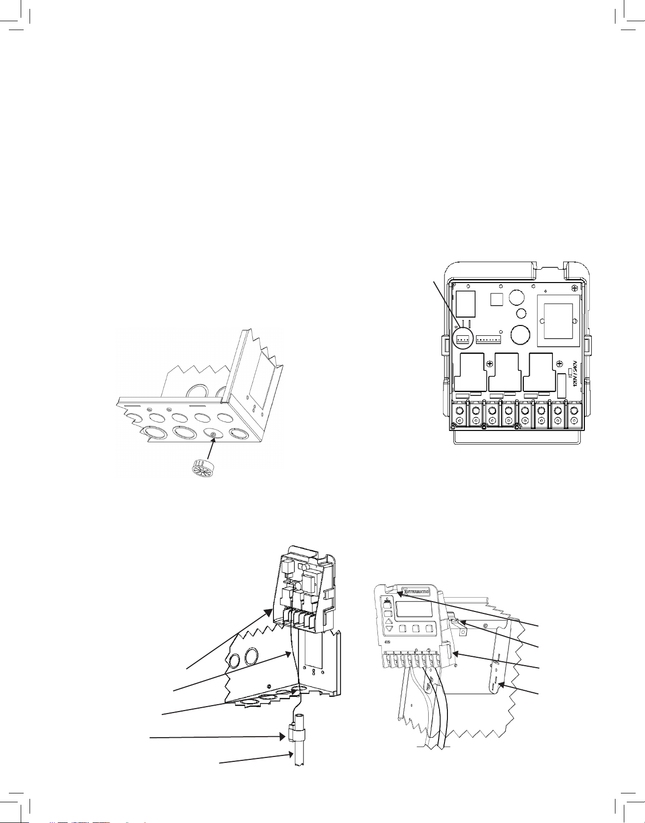
Step #1
Install the Shutter Bushing through one of the
available 3/4” knockouts at the bottom of the enclo-
sure. If a low voltage raceway is present, choose
a knockout at the entrance of the raceway.
Step #3
Route the freeze probe cord from the bottom of the
enclosure, into and through the shutter bushing.
Connect the probe connector to the back of the
Multipurpose control. Snap the freeze probe
onto a nearby piece of conduit near the pool
or spa equipment pad.
Step #4
Rotate the mechanism until the Tabs line up with
the slots. Slide the bottom half of the mechanism
into slots, and push the top half into the bracket
until the mechanism snaps into the bracket slot.
Step #2
Freeze Probe Connection
Locate the freeze probe
connector on the back of
the Multipurpose control.
The connector is polar
-ized and can only plug in
one way. Do not force
the connector on the
wrong way.
NOTE
If low voltage raceway is present,
route cord through raceway and
attach to back of control.
NOTE
If conduit is to be
used, the shutter
bushing is not
necessary.
Shutter Bushing
Intermatic Mechanism
Freeze Probe Cord
Shutter Bushing
Freeze Probe
Bracket Slot
Bracket
Tabs
Slot
Any available piece of conduit
158PA11041.indd 1 2/5/09 2:37:40 PM
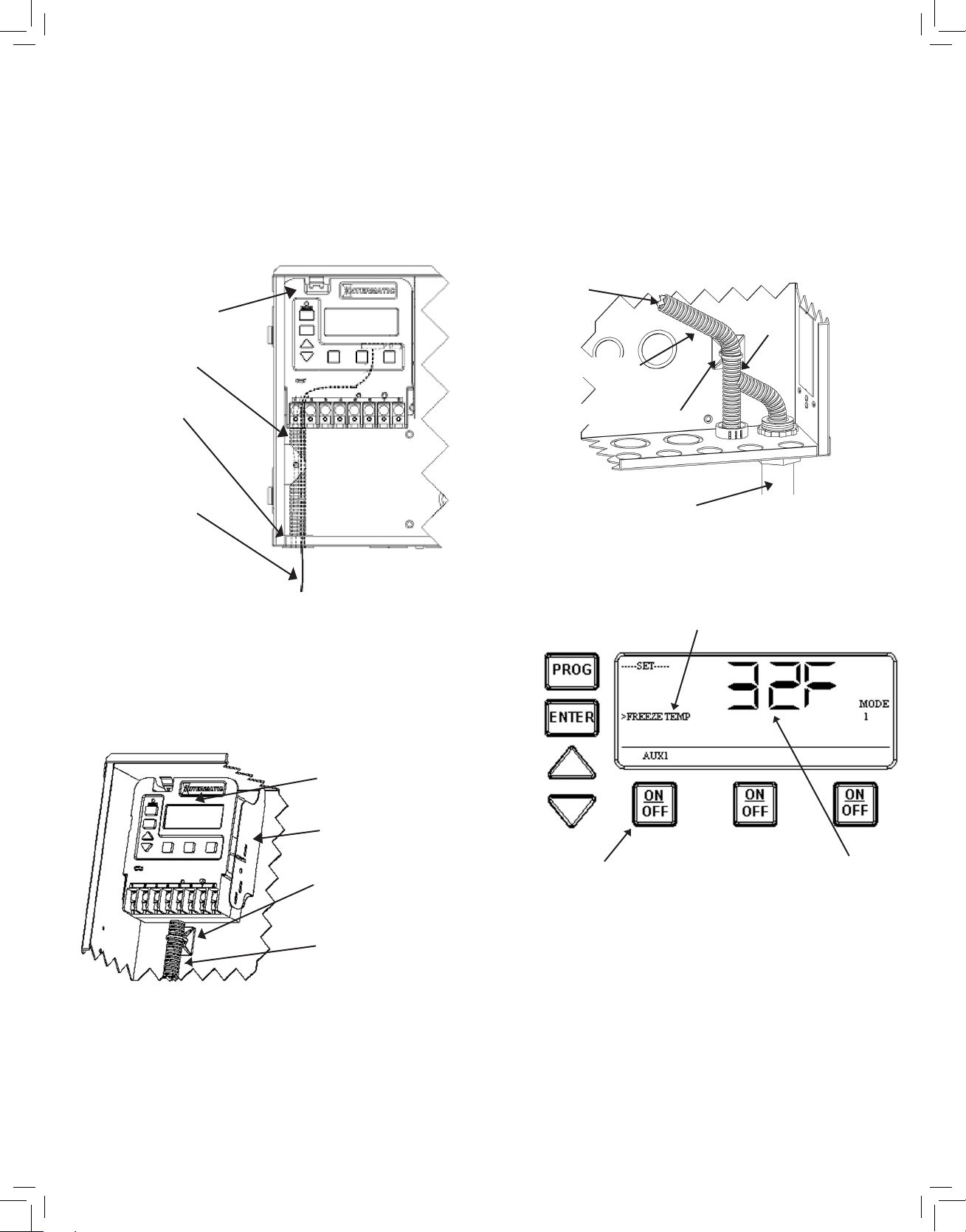
SKIP STEPS 5 AND 6 If LOW VOLTAGE RACEWAY
IS PRESENT IN ENCLOSURE AS THIS PROVIDES
THE REQUIRED SEPARATION OF CIRCUITS
Step #5
If there is not enough corrugated tubing
available in the kit to install two separate tubes,
a splice connecting one tube to the adjacent
tube is acceptable.
Step #5
Cut the corrugated tubing so there is enough
length to reach from the bottom of the control
down to the shutter bushing. Slip the tubing
over the freeze probe cord.
Step #6
Included in the Class 2 Wiring Isolation Kit is a
Cable Tie Retainer. Use this retainer to secure
the top of the corrugated tubing to the back of the
Intermatic enclosure, as close to the bottom of the
mechanism as possible.
INTERMATIC INCORPORATED
http://www.intermatic.com
Intermatic Plaza, Spring Grove, Illinois 60081-9698
158PA11041
Step #7
1. Use the program key to save and advance
to the Freeze Temperature setting.
The 1st circuit is the factory selected default, and
32°F is the default temperature setting.
2. Use the Up and Down arrow keys to increase
or decrease the desired freeze temperature trip
point. The range available is 32°F thru 44°F.
3. After you have selected the proper temperature,
push and release the desired ON/OFF keys to indi-
cate which circuits should come ON when freeze
condition exists.
4. When programming is complete, push and
release the Enter key or Program key to end your
programming session.
FOR FREEZE PROGRAMMING INSTRUCTIONS
REFER TO YOUR MULTIPURPOSE CONTROL
MANUAL FOR COMPLETE INSTRUCTIONS,
OR STEP #7 FOR A QUICK REVIEW
Intermatic Mechanism
Corrugated Tubing
Shutter Bushing
Freeze Probe Cord
Intermatic Mechanism
Enclosure
Cable Tie Retainer
Corrugated Tubing
Connect to
Mechanism
Adjacent Tube
Splice
Example #2
Example #1
Cable Tie Retainer
Conduit attached
To enclosure
158PA11041.indd 2 2/5/09 2:37:41 PM