WWW.NUTONE.CA
Serial number:
99045654-001J
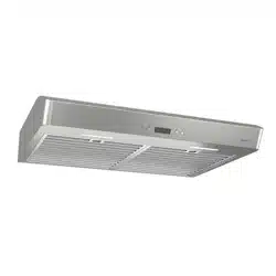
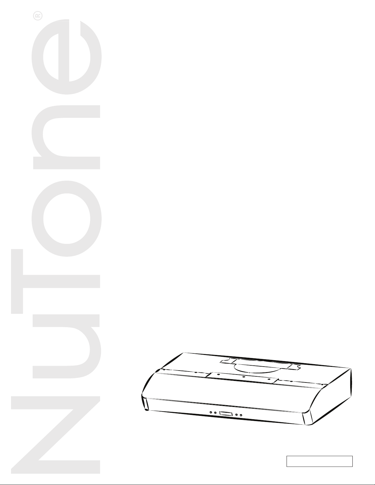
RANGE HOOD
Series: AVDN1
INSTALLATION, USE
AND CARE MANUAL
WWW.NUTON

INSTALLATION MANUAL
TABLE OF CONTENTS
2
Safety . . . . . . . . . . . . . . . . . . . . . . . . . . . . . . . . . 3-4
Operation . . . . . . . . . . . . . . . . . . . . . . . . . . . . . . 5-6
Cleaning and Maintenance . . . . . . . . . . . . . . . . . 7
Motors
Grease Filters
Non-Ducted Recirculation Filters
Fan Wheels
Stainless Steel Cleaning
Painted Finish Cleaning
Installation . . . . . . . . . . . . . . . . . . . . . . . . . . . . 8-21
Recommended Tools
and Accessories for Installation . . . . . . . . . . . . 8
Install Ductwork (Ducted Installations Only) . . . 8
Contents . . . . . . . . . . . . . . . . . . . . . . . . . . . . . . 9
Prepare the Hood . . . . . . . . . . . . . . . . . . . . . . . 10-13
Prepare the Hood Location . . . . . . . . . . . . . . . . 14
EZ1 Person Installation . . . . . . . . . . . . . . . . . 14-16
Install the Hood (EZ1 Bracket) . . . . . . . . . . . . 17-18
Standard Installation . . . . . . . . . . . . . . . . . . . 19
Install the Hood (Standard Installation) . . . . . 20
Connect the Wiring . . . . . . . . . . . . . . . . . . . . . . 21
Install the Filters . . . . . . . . . . . . . . . . . . . . . . . . 21
Wiring Diagram . . . . . . . . . . . . . . . . . . . . . . . . . 22
Service Parts . . . . . . . . . . . . . . . . . . . . . . . . . 23-24
Warranty . . . . . . . . . . . . . . . . . . . . . . . . . . . . . . . 25
INSTALLATION MANUAL
SAFETY
3
READ AND SAVE THESE INSTRUCTIONS
!
Intended for domestic cooking only
!
INSTALLER: LEAVE THIS MANUAL WITH HOMEOWNER.
Register your range hood online at www.nutone.ca
!
WARNING
TO REDUCE THE RISK OF FIRE, ELECTRIC SHOCK, OR INJURY TO
PERSONS, OBSERVE THE FOLLOWING:
• Use this unit only in the manner intended by the manufacturer. If you have
questions, contact the manufacturer at the address or telephone number
listed in the warranty.
• Before servicing or cleaning unit, switch power off at service panel and
lock the service disconnecting means to prevent power from being
switched on accidentally. When the service disconnecting means cannot
be locked, securely fasten a prominent warning device, such as a tag, to
the service panel.
• Installation work and electrical wiring must be done by a qualified
person(s) in accordance with all applicable codes and standards, including
fire-rated construction.
• Sufficient air is needed for proper combustion and exhausting of
gases through the flue (chimney) of fuel burning equipment to prevent
backdrafting. Follow the heating equipment manufacturer’s guidelines and
safety standards such as those published by the National Fire Protection
Association (NFPA) and the American Society for Heating, Refrigeration
and Air Conditioning Engineers (ASHRAE) and the local code authorities.
• When cutting or drilling into wall or ceiling, do not
damage electrical wiring and other hidden utilities.
• Ducted fans must always be vented to the outdoors.
• Do not use this unit with any additional solid-state speed control device.
• To reduce the risk of fire, use only metal ductwork.
• This unit must be grounded.
• As an alternative, this product may be installed with the UL-approved cord
kit designated for the product, following instructions packed with the cord
kit.
• When applicable local regulations comprise more restrictive installation
and/or certification requirements, the aforementioned requirements prevail
on those of this document and the installer agrees to conform to these at
his own expense.
INSTALLATION MANUAL
SAFETY
4
!
WARNING
TO REDUCE THE RISK OF A RANGE TOP GREASE FIRE:
a) Never leave surface units unattended at high settings. Boilovers cause
smoking and greasy spillovers that may ignite. Heat oils slowly on low or
medium settings.
b) Always turn hood ON when cooking at high heat or when flambeing food
(i.e.: Crêpes Suzette, Cherries Jubilee, Peppercorn Beef Flambé).
c) Clean ventilating fan frequently. Grease should not be allowed to
accumulate on fan, filters or in exhaust ducts.
d) Use proper pan size. Always use cookware appropriate for the size of
the surface element.
TO REDUCE THE RISK OF INJURY TO PERSONS IN THE EVENT OF A
RANGE TOP GREASE FIRE, OBSERVE THE FOLLOWING*:
1. SMOTHER FLAMES with a close-fitting lid, cookie sheet or metal tray,
then turn off the burner. BE CAREFUL TO PREVENT BURNS. IF THE
FLAMES DO NOT GO OUT IMMEDIATELY, EVACUATE AND CALL
THE FIRE DEPARTMENT.
2. NEVER PICK UP A FLAMING PAN — You may be burned.
3. DO NOT USE WATER, including wet dishcloths or towels — This could
cause a violent steam explosion.
4. Use an extinguisher ONLY if:
A. You own a Class ABC extinguisher and you know how to operate it.
B. The fire is small and contained in the area where it started.
C. The fire department has been called.
D. You can fight the fire with your back to an exit.
* Based on “Kitchen Fire Safety Tips” published by NFPA.
!
CAUTION
• For indoor use only.
• For general ventilating use only. Do not use to exhaust hazardous or explosive materials
and vapors.
• To avoid motor bearing damage and noisy and/or unbalanced fan wheels, keep drywall
spray, construction dust, etc. off range hood.
• Your hood motor has a thermal overload which will automatically shut off the motor if it
becomes overheated. The motor will restart when it cools down. If the motor continues to
shut off and restart, have the hood serviced.
• For best capture of cooking fumes, the bottom of the hood MUST NOT BE LESS than 18”
and at a maximum of 30” above the cooking surface.
• Always follows the cooking equipment manufacturer’s requirements regarding the
ventilation needs.
• To reduce the risk of fire and to properly exhaust air, be sure to duct air outside — Do not
exhaust air into spaces within walls or ceiling or into attics, crawl space or garage.
• When installing, servicing or cleaning the unit, it is recommended to wear safety glasses
and gloves.
• Please read specification label on product for further information and requirements.
INSTALLATION MANUAL
OPERATION
5
Operation
Always turn your hood on before you begin cooking to establish an air flow in the kitchen.
Let the blower run for a few minutes to clear the air after you turn off the range. This will help
keep the whole kitchen cleaner and fresher.
Operate the hood as follows:
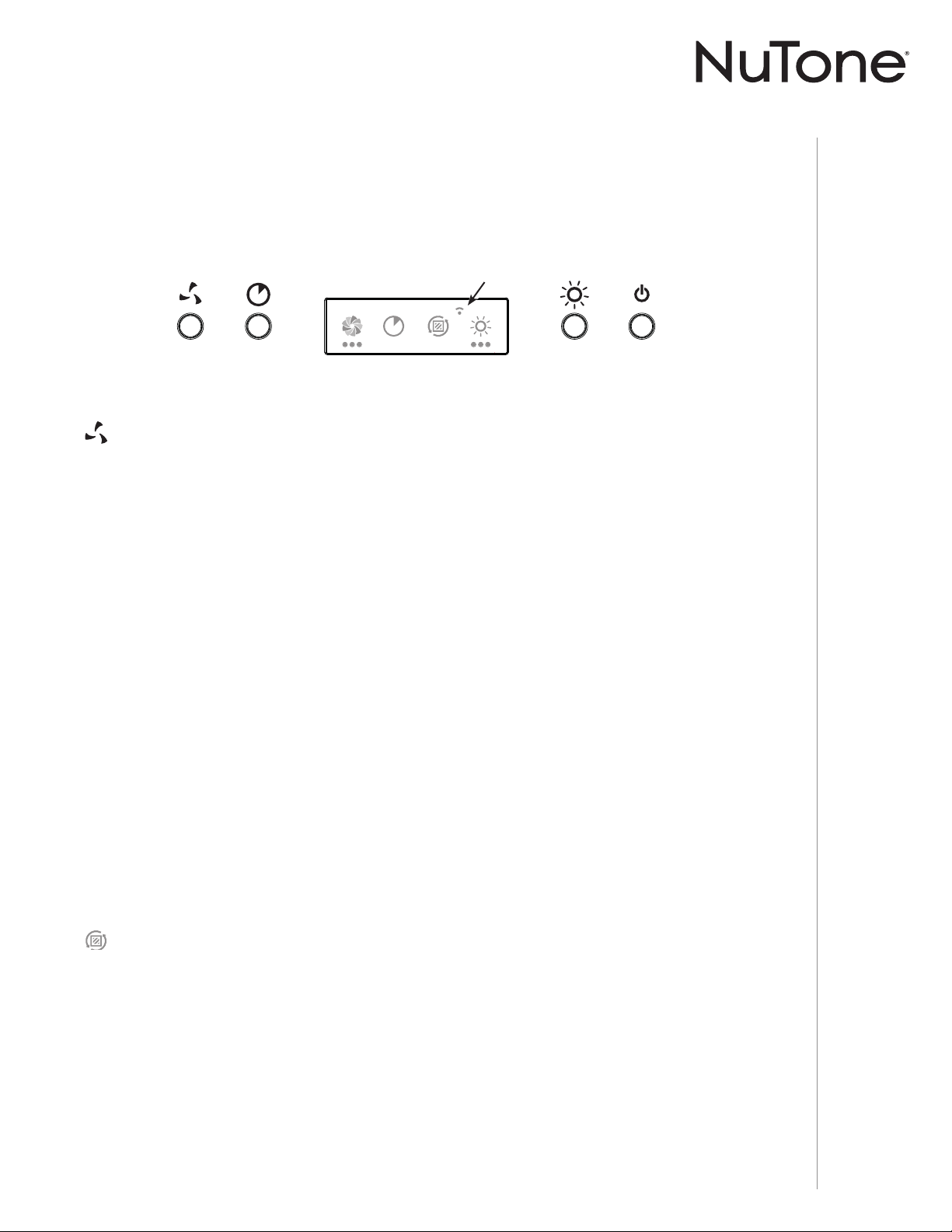
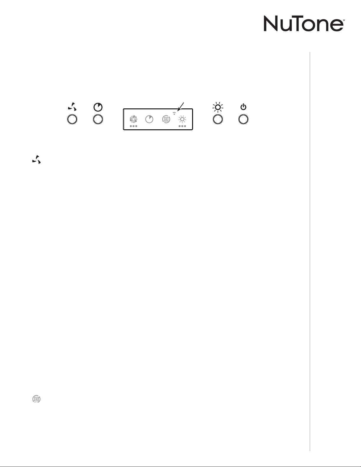
BLOWER ACTIVATION/SPEED LEVEL CHANGE/FILTER INDICATOR RESET
When blowers are OFF, press on this push button to turn ON the blowers at the last saved speed.
If there was no speed saved, the blowers will be set on LOW speed.
NOTE: When LOW speed is activated from OFF, the blowers start on MEDIUM speed for a very
short lapse of time, and then resume to LOW speed.
To change the blower speed, press this button again until the desired speed is reached (from LOW
to MEDIUM to HIGH speed to OFF). Each time a blower speed is activated, a rotating blower
icon appears on left side of LCD screen, with dot(s) under it (slow for LOW with one dot, faster for
MEDIUM with 2 dots and fastest for HIGH with 3 dots).
When blowers are on (no matter the speed level), press and hold this button until the blower icon
disappears from the LCD screen; this will turn off the blowers and save the blower speed chosen.
Heat Sentry™
This hood is equipped with a protective device that activates the blowers when an abnormally high
heat level is detected while the blowers are activated. During the Heat Sentry activation, this device
takes control of the blowers and set them on MEDIUM speed while all dots under the blower icon
blink. However, the lights can be still controlled. The blowers will remain on MEDIUM speed until
the heat is back to normal, they then return to the speed previously selected.
NOTE: When excessive heat is detected, Heat Sentry will shut off both blowers and lights while all
dots under the blower icon will blink faster. Both blowers and lights will remain off until the
ambient temperature cools down; the blowers will then start on MEDIUM speed (the lights
can be controlled again). The blowers will remain on MEDIUM speed until the heat is back
to normal, they then return to the speed previously selected.
NOTE: At range hood start-up or after a power failure, a small icon (1) appears shortly
(for ± 2 seconds) on LCD screen; this is normal.
FILTER CLEANING REMINDER
This icon appears on LCD screen 30 seconds after turning OFF the blowers when it is time to
clean hood and filters (refer to Cleaning and Maintenance on page 7). This happens every time
the blowers are turned OFF until the filter cleaning reminder has been reset. Once the cleaning is
done, reset the filter cleaning reminder by pressing on blower activation push button for 3 seconds
while the icon appears on LCD screen for 30 seconds.
1

INSTALLATION MANUAL
OPERATION
6
ON LIGHTING/LIGHT INTENSITY CHANGE
Press this button to turn on the lights at the last saved intensity; the light icon appears on right side
of LCD screen and the number of dots below it shows which light intensity is on (one dot for LOW,
two dots for MEDIUM and three dots for HIGH).
To change the light intensity, press button until the desired level is reached (from HIGH intensity,
pressing again will shut off the lights).
When lights are on (no matter the light intensity), press and hold this button until the light icon
disappears from the LCD screen; this will shut off the lights and save the chosen light intensity.
The LED modules included with this hood are the latest in LED cooktop illumination technology
specially designed to operate in the elevated temperatures of cooking - offering bright lighting and
lasting up to 25 times as long as a standard bulb and greater reliability than typical replacement
LED bulbs.
MASTER ON/OFF
Press this button to turn on the ligths and the blowers at the last saved intensity. When either lights
or blowers are ON, pressing this button will memorize the current blower speed and lighting level
prior to shut them OFF.
DELAY OFF
When the blowers are on, press this button to activate the delay function. This icon appears on LCD
screen beside the blower icon to indicate the function is on. The blowers will continue to operate for
10 minutes and then, will shut off automatically (both blower and delay icons will disappear from
LCD screen). When Delay off is activated, it is possible to change the blower speed by pressing on
blower push button without affecting the remaining time of the delay.
To cancel the delay off function before the end of the 10-minute cycle, press this button again.

INSTALLATION MANUAL
CLEANING AND MAINTENANCE
7
Cleaning and Maintenance
Proper maintenance of the Range Hood will assure proper performance of the unit.
MOTORS
The motors are permanently lubricated and never need oiling. If the motor bearings make
excessive or unusual noise, replace the motor with the exact service motor. The fan wheel should
also be replaced.
GREASE FILTERS
The grease filters should be cleaned frequently. Use a warm dishwashing detergent solution.
Clean all-metal filters using a non-phosphate detergent. Discoloration of the filters may occur if
using phosphate detergents, or as a result of local water conditions - but this will not affect filter
performance. This discoloration is not covered by the warranty.
NON-DUCTED RECIRCULATION FILTERS
The non-ducted recirculation filters should be changed every 3 to 6 months. Replace more often
if your cooking style generates extra grease, such as frying and wok cooking. Refer to installation
instructions included with non-ducted recirculation filters.
FAN WHEELS
The center of the fan wheels should be cleaned frequently. Use a clean cloth soaked with warm
detergent solution.
STAINLESS STEEL CLEANING
Do:
• Regularly wash with clean cloth or rag soaked with warm water and mild soap or liquid dish
detergent.
• Always clean in the direction of original polish lines.
• Always rinse well with clear water (2 or 3 times) after cleaning. Wipe dry completely.
• You may also use a specialized household stainless steel cleaner.
Don’t:
• Use any steel or stainless steel wool or any other scrapers to remove stubborn dirt.
• Use any harsh or abrasive cleansers.
• Allow dirt to accumulate.
• Let plaster dust or any other construction residues reach the hood. During construction/
renovation, cover the range hood to make sure no dust sticks to the stainless steel surface.
Avoid when choosing a detergent:
• Any cleaners that contain bleach will attack stainless steel.
• Any products containing: chloride, fl uoride, iodide, bromide will deteriorate surfaces
rapidly.
• Any combustible products used for cleaning such as acetone, alcohol, ether, benzol, etc.,
are highly explosive and should never be used close to a range.
PAINTED FINISH CLEANING:
Clean with warm water and mild detergent only. If discoloration occurs, use a finish polish such
as automotive polish. (DO NOT use rough abrasive cleaner or porcelain cleaner.)
INSTALLATION MANUAL
INSTALLATION
8
Recommended Tools and Accessories
for Installation
• Measuring tape
• Phillips screwdriver no. 2
• Nutdriver or socket 11/32”
• Flat blade screwdriver (to open knockout holes)
• Drill, 1/8” drill bit and 1½” hole saw (to mark holes for ducting and cut electrical access hole)
• 7/64” drill bit (to drill holes for EZ1 brackets mounting screws)
• 7” round duct plate, not included (for 7’’ round vertical ducting installation, part no.: SR680508)
• Wood shims (2) and wood screws (4) (required for standard installation to framed cabinet)
• Saw (to cut holes for ducted application)
• Sheet metal shears (ducted installation only, for duct adjustment)
• Pliers (ducted installation only, for duct adjustment)
• Metal foil duct tape (for ducted applications)
• Scissors (to cut metal foil duct tape)
• Pencil
• Wire stripper
• Strain relief, 1/2” diameter (to secure house wiring cable to the hood)
• BP87Q Damper (needed if 7-in. round duct is used)
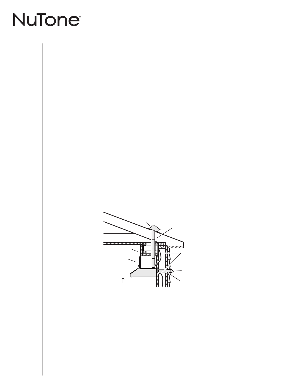
Install Ductwork (Ducted Installations Only)
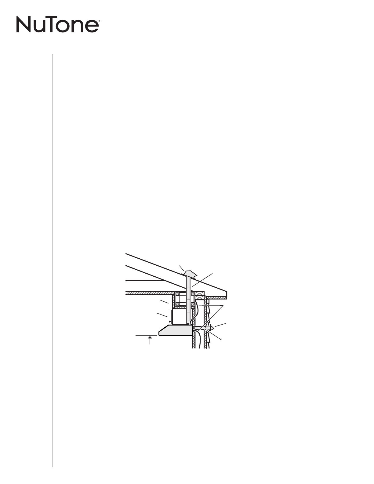
NOTE: Distances over 30” are at the installer and user discretion.
1 ] Determine whether hood will discharge vertically (3¼” x 10” or 7” round),
or horizontally (3¼” x 10” only).
2 ] Decide where the ductwork will run between the hood and the outdoors.
3 ] Choose a straight, short duct run to allow the hood to perform most efficiently. Long duct
runs, elbows and transitions will reduce the performance of the hood. Use as few of them as
possible. When possible, use at least 2 foot straight runs before any turns. Larger ductwork
may be required for best performance with longer duct runs.
NOTE: To use 6” round ducting, install a 3¼” x 10” to 6” round transition (not included). The
performances may be affected.
4 ] Install wall cap or roof cap (sold separately); ensure there is no leak in house insulation.
Connect metal ductwork to cap and work back towards the hood location. Use 2” metal foil
duct tape to seal the joints between ductwork sections.
For ADA compliance installation guidelines, please type the model number into our website.
SOFFIT
18" MIN - 30" MAX
ABOVE
COOKING SURFACE
CABINET
3¼" X 10" DUCT
(FOR HORIZONTAL DISCHARGE)
WALL CAP
ROOF CAP
3¼" X 10" OR
7" ROUND DUCT
(FOR VERTICAL
DISCHARGE
)
HOUSE WIRING
(TOP OR BACK OF HOOD)
HOOD
INSTALLATION MANUAL
INSTALLATION
9
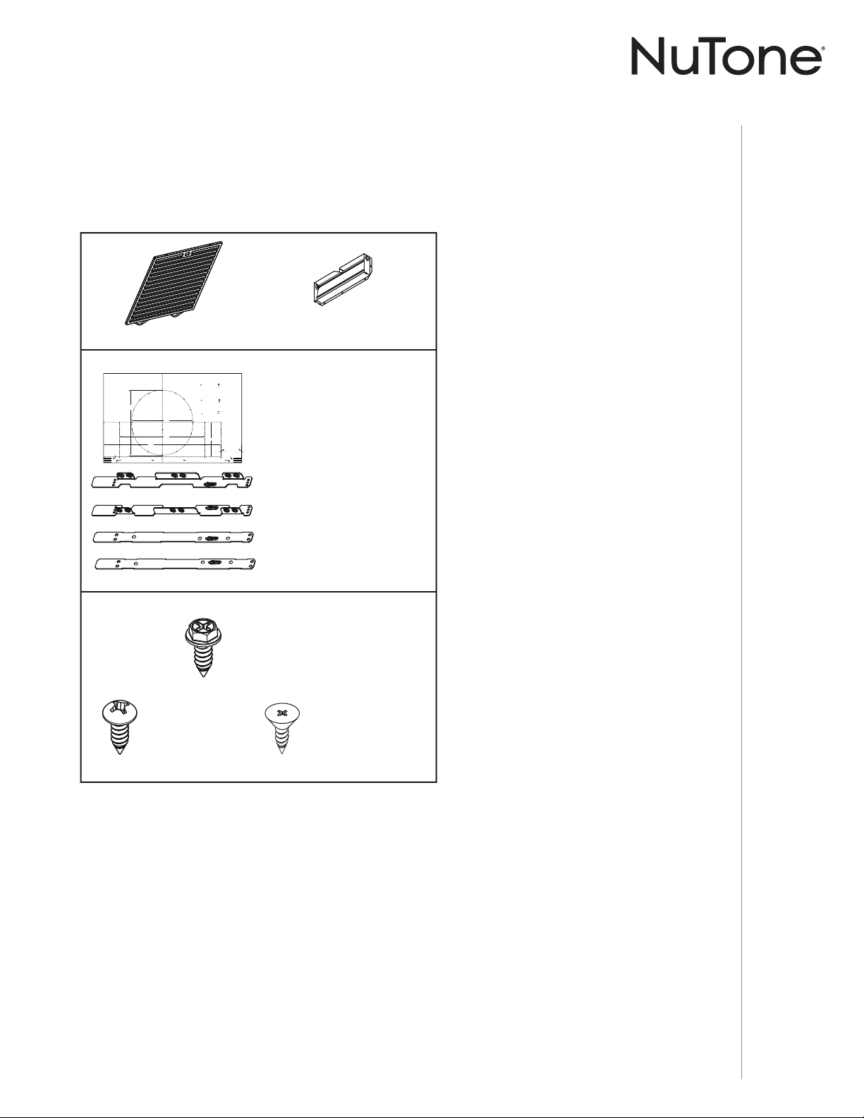
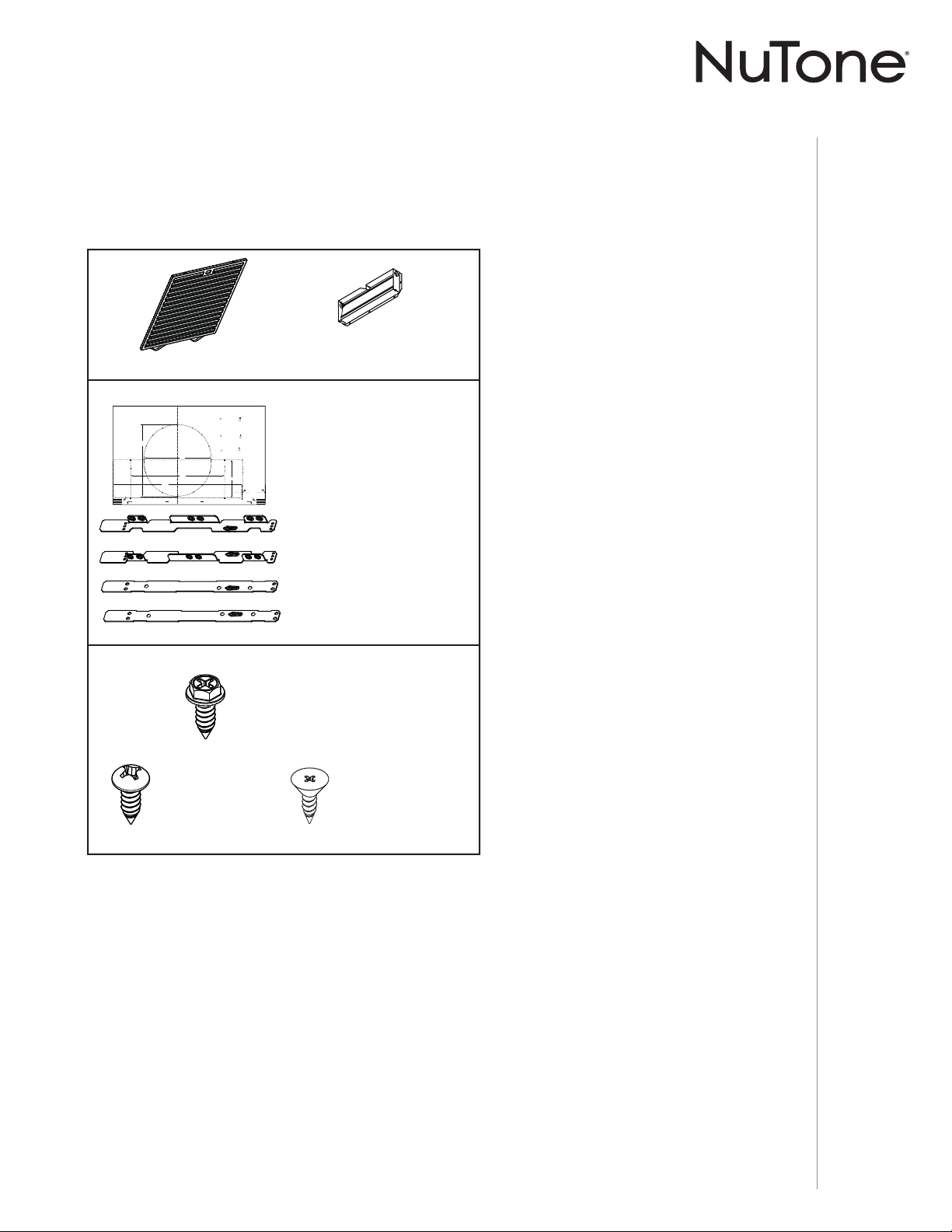
Contents
Before proceeding to the installation, check the contents of the box. If items are missing or
damaged, contact the manufacturer.
Make sure that the following items are included:
(1) 3¼” X 10”
D
AMPER ASSEMBLY
(1) PARTS BAG** CONTAINING:
(6) N
O. 8 X 5/8”
RD. HD.
W
OOD SCREWS
(2) INSTALLATION BRACKETS*
FOR FRAMED CABINET
(2) INSTALLATION BRACKETS*
FOR FRAMELESS CABINET
(1) TEMPLATE FOR DUCTING
(PRINTED BOTH SIDES)
(4) NO. 8-18 X 1/2”
M
ETAL SCREWS
(6) NO. 8 X 1/2”
C
OUNTERSUNK
WOOD SCREWS
EZ1 COMPONENTS
C
L
AB
Apoyar este borde contra la pared de atrásPlace this edge against back wall
VERTICAL EXHAUST
S
A
A
V
RTICAL EX
= 3¼” x 10”
= 3¼” x 14”
RECTANGULAR DUCTING7” ROUND DUCTING
OR
Use this template for marking;do not attempt to cut out the ducting hole through it.
NOTE: These cutouts are clearance holes; they do not need to be the exact size of ducting.
= 3¼ po x 10 po
= 3¼ po x 14 po
CONDUIT RECTANGULAIRECONDUIT ROND DE 7 PO
OU
= 3¼ pulg. x 10 pulg.
= 3¼ pulg. x 14 pulg.
CONDUCTO RECTANGULARCONDUCTO REDONDO
DE
7 PULG.
O
Appuyer ce bord au mur arrière
Utiliser ce gabarit pour marquer vos repères;ne pas tenter de découper
le trou pour le conduit à travers le gabarit.
NOTE : Les découpes incluent le jeu nécessaire à l’installation; elles ne doivent pas
être du format exact des conduits.
Use esta plantilla para crear marcados;no trate de cortar el
agujero del conducto a través de la plantilla.
NOTA: To be translated in Spanish.
MARK WHERE INDICATED
FOR THE APPROPRIATE SIZE DUCT OPENING
MARQUER LES REPÈRES AUX ENDROITS INDIQUÉS SELON
LE FORMAT DE CONDUIT UTILISÉ
TITLE TO BE TRANSLATED IN SPANISH
Electrical access hole center
A = single blower hood
B = double blower hood
Centre du trou pour fil
d’alimentation électrique
A = hotte ventilateur simple
B = hotte ventilateur double
To be translated in Spanish
Electrical access hole center
A = single blower hood
B = double blower hood
4¼”
10½”
14½”
8”
7½”
C
C
C
Bend template along graduated
scale when installing to framed
cabinet.
Pour une installation sous une
armoire à fond en retrait, utiliser les
lignes pour mesurer l’épaisseur du
décalage causé par le mur de
l’armoire et plier le gabarit en
conséquence.
To be translated in Spanish.
* FIND EZ1 BRACKETS ATTACHED INSIDE OF HOOD
(2) GREASE FILTERS
** FIND PARTS BAG INSIDE OF HOOD

INSTALLATION MANUAL
INSTALLATION
10
B
C
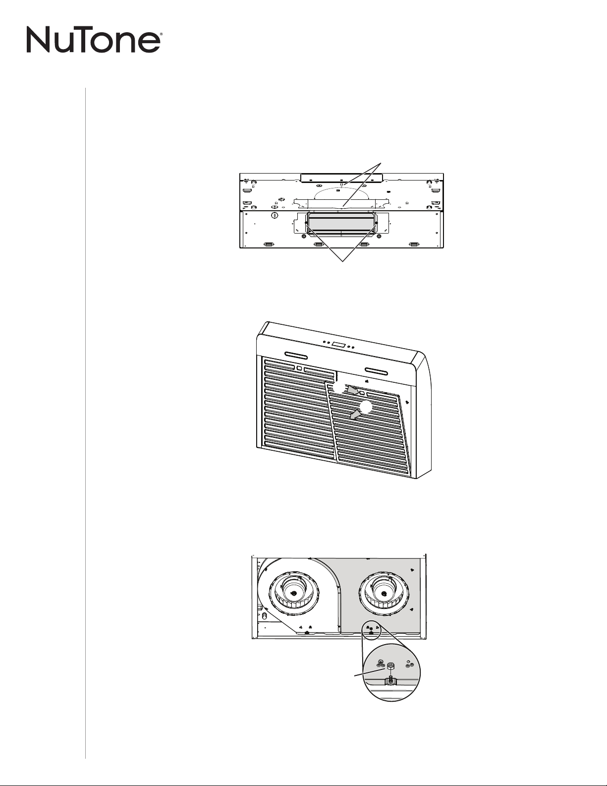
Prepare the Hood
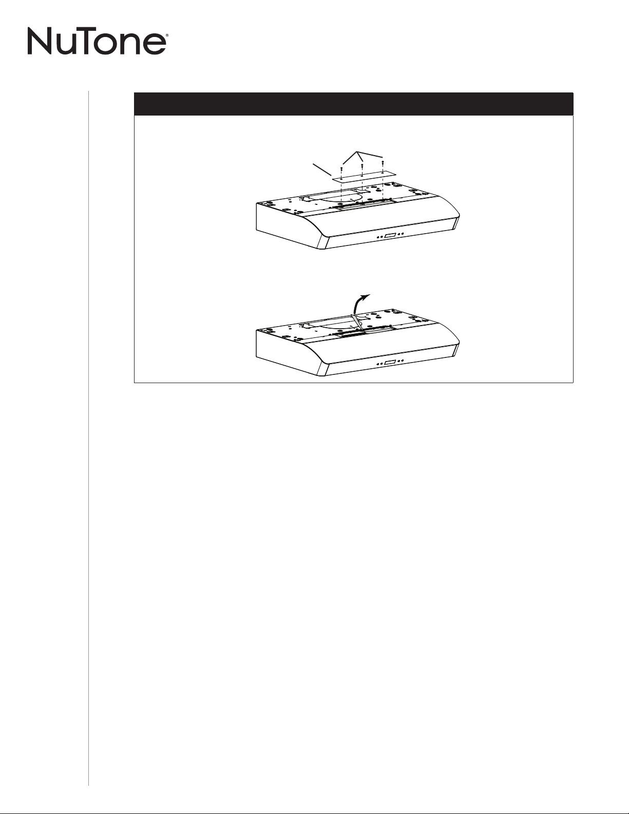
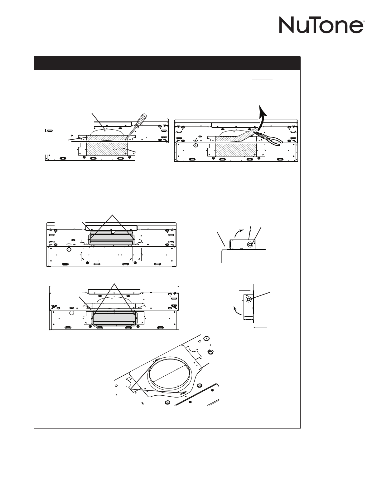
1 ] If present, remove all protective polyfilm from the hood and/or parts.
2 ] Remove two screws from the top of the hood. Remove the adapter/damper from back of
hood (see illustration below). Keep the screws for further use.
3 ] Using the finger cup, remove the grease filters from the hood by pushing down and tilting
filters out .
1
2
3
45
6
7
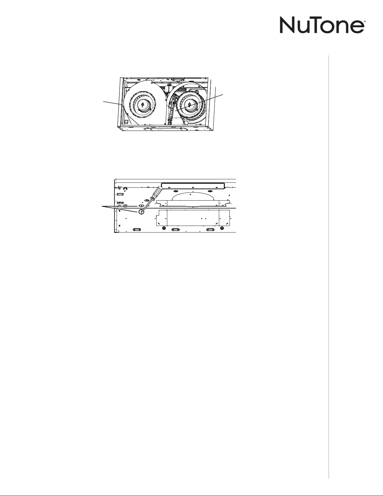
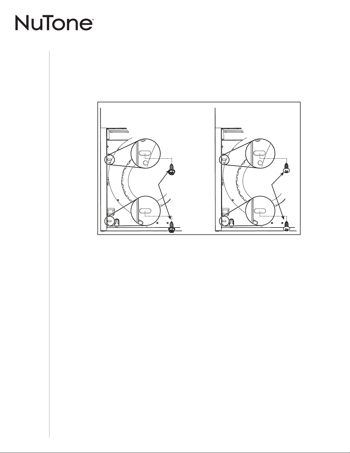
4 ] Using a 11/32” nutdriver or socket, remove the lock nut retaining the flange of the right cover
plate (shaded part on illustration below) to the inner back of hood (see inset). Remove the
right cover plate retaining screws (7 screws), then set the blower cover along with its screws
and nut aside.
BACK OF HOOD
LOCK NUT
2 SCREWS
2 SCREWS
INSTALLATION MANUAL
INSTALLATION
11
6 ] Remove Electrical Power Cable Knockout from top (vertical wiring) or back (horizontal wiring)
of hood. For knockout removed from back of hood, install an appropriate strain relief,
1/2” diameter (not included). For knockout removed from top of hood, the strain relief will be
installed later.
ELECTRICAL
POWER CABLE
KNOCKOUT
5 ] Remove the parts bag, taped on the inner back of hood, near the left corner. Remove the EZ1
brackets from inside the hood by cutting off the tie wrap. Discard the tie wrap.
EZ1 BRACKETS
PARTS BAG LOCATION
INSTALLATION MANUAL
INSTALLATION
12
RECIRCULATION
COVER PLATE
SCREWS
NON-DUCTED INSTALLATION ONLY
7 ] Remove 3 screws retaining the recirculation cover plate to the hood. Discard this plate
with its screws.
8 ] Peel off and discard the membrane covering the recirculation grille, ensuring the
openings are totally cleared.
INSTALLATION MANUAL
INSTALLATION
13
DUCTED INSTALLATION ONLY
TIP: Insert a small length of duct over the 3¼” x 10” damper assembly (for rectangular ducting) or
7” round (for round ducting) and seal the joint using aluminum foil duct tape to ease connection
with the house ductwork.
9 ] Remove 3¼” x 10” vertical, 3¼” x 10” horizontal (both are the rectangular central
knockout plates, see hatched areas) or 7-inch round knockout plate as appropriate for
your ducting method (see FIGURES 1 A and 1 B).
NOTE: To accommodate off-center ductwork, the 7” round duct plate can be installed up
to 1/2” on either side of the hood center.
7” ROUND KNOCKOUT
PLATE (ALSO REMOVE
3¼” X 10” VERTICAL
KNOCKOUT PLATE)
3¼” X 10”
VERTICAL
KNOCKOUT
PLATE
3¼” X 10”
HORIZONTAL
KNOCKOUT
PLATE
FIGURE 1 A
7” ROUND
DUCT
PLATE
SCREWS
FIGURE 3
FIGURE 1 B
10 ] Attach 3¼” x 10” Damper Assembly on top OR back of hood (if using 3¼” x 10” duct;
shaded part in F
IGURE 2 A below) or 7” Round Duct Plate (if using 7-inch round duct,
FIGURE 3) over the knockout opening. When installed, the 3¼” x 10” damper assembly
must open as shown in FIGURE 2 B.
3¼” X 10”
DAMPER
ASSEMBLY
TOP/BACK
EDGE OF
HOOD
DAMPER
FLAP
PIVOT
SCREWS
FIGURE 2 A FIGURE 2 B
3¼” X 10”
DAMPER
ASSEMBLY
BACK OF
HOOD
DAMPER
FLAP
PIVOT
SCREWS
INSTALLATION MANUAL
INSTALLATION
14
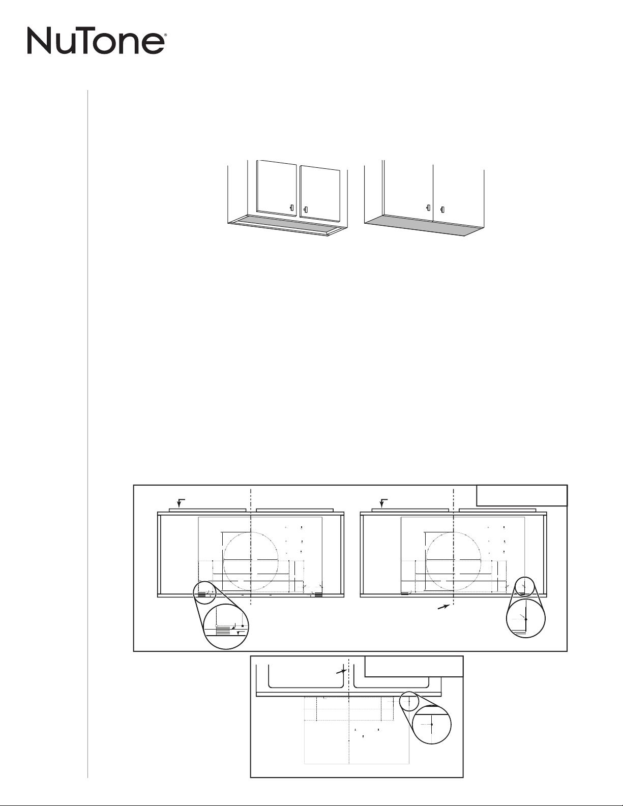
Prepare the Hood Location
NOTE: Before starting installation, read all the steps of these instructions.
Use the illustration below to identify your kitchen cabinet type.
EZ1 One-person installation system
EZ1 installation is designed for use with kitchen cabinets that have the same width designation as
the range hood width. If the cabinet is greater than 1/2” wider than the range hood width, please
use the standard installation method.
1 ] Use the proper template for vertical OR horizontal disharge (included) for placement of
ductwork and electrical cutout in cabinet or wall. For a non-ducted installation, DO NOT cut a
duct access hole, only cut the hole for electrical wiring. If replacing a hood and plan to use
the existing duct and electrical, steps 2 to 5 may not be necessary. If so, skip to step 6.
2 ] Measure and mark the hood center line on cabinet bottom.
3 ] Align the center line on template with the hood center line marked on the bottom of the
cabinet, placing the edge (where indicated) of the template against back wall. When using
with framed cabinet for vertical exhaust installation, fold over rear edge of template equal
to the depth of the cabinet frame at the wall (use graduations on template, C locations on
template). Tape the template in place.
NOTE: When facing the installation, A and B (on template) must be at right.
CABINET FRONT
C
L
AB
Apoyar este borde contra la pared de atrásPlace this edge against back wall
VERTICAL EXHAUST
A
S
A
A
V
RTICAL EX
= 3¼” x 10”
= 3¼” x 14”
RECTANGULAR DUCTING7” ROUND DUCTING
OR
Use this template for marking; do not attempt to cut out the ducting hole through it.
NOTE: These cutouts are clearance holes; they do not need to be the exact size of ducting.
= 3¼ po x 10 po
= 3¼ po x 14 po
CONDUIT RECTANGULAIRECONDUIT ROND DE 7 PO
OU
= 3¼ pulg. x 10 pulg.
= 3¼ pulg. x 14 pulg.
CONDUCTO RECTANGULARCONDUCTO REDONDO
DE
7 PULG.
O
Appuyer ce bord au mur arrière
Utiliser ce gabarit pour marquer vos repères;ne pas tenter de découper
le trou pour le conduit à travers le gabarit.
NOTE : Les découpes incluent le jeu nécessaire à l’installation; elles ne doivent pas
être du format exact des conduits.
Use esta plantilla para crear marcados; no trate de cortar el
agujero del conducto a través de la plantilla.
NOTA: To be translated in Spanish.
MARK WHERE INDICATED
FOR THE APPROPRIATE SIZE DUCTOPENING
MARQUER LES REPÈRES AUXENDROITS INDIQUÉS SELON
LE FORMAT DE CONDUIT UTILISÉ
TITLE TO BE TRANSLATED IN SPANISH
Electrical access hole center
A = single blower hood
B = double blower hood
Centre du trou pour fil
d’alimentation électrique
A = hotte ventilateur simple
B = hotte ventilateur double
To be translated in Spanish
Electrical access hole center
A = single blower hood
B = double blower hood
4¼”
10½”
14½”
8”
7½”
C
C
C
Bend template along graduated
scale when installing to framed
cabinet.
Pour une installation sous une
armoire à fond en retrait, utiliser les
lignes pour mesurer l’épaisseur du
décalage causé par le mur de
l’armoire et plier le gabarit en
conséquence.
To be translated in Spanish.
P
C
CABINET FRONT
C
L
AB
VERTICAL EXHAUST
A
S
A
A
V
RTICAL EX
= 3¼” x 10”
= 3¼” x 14”
RECTANGULAR DUCTING7” ROUND DUCTING
OR
Use this template for marking; do not attempt to cut out the ducting hole through it.
NOTE: These cutouts are clearance holes; they do not need to be the exact size of ducting.
= 3¼ po x 10 po
= 3¼ po x 14 po
CONDUIT RECTANGULAIRECONDUIT ROND DE 7 PO
OU
= 3¼ pulg. x 10 pulg.
= 3¼ pulg. x 14 pulg.
CONDUCTO RECTANGULARCONDUCTO REDONDO
DE
7 PULG.
O
Utiliser ce gabarit pour marquer vos repères;ne pas tenter de découper
le trou pour le conduit à travers le gabarit.
NOTE : Les découpes incluent le jeu nécessaire à l’installation; elles ne doivent pas
être du format exact des conduits.
Use esta plantilla para crear marcados; no trate de cortar el
agujero del conducto a través de la plantilla.
NOTA: To be translated in Spanish.
MARK WHERE INDICATED
FOR THE APPROPRIATE SIZE DUCTOPENING
MARQUER LES REPÈRES AUXENDROITS INDIQUÉS SELON
LE FORMAT DE CONDUIT UTILISÉ
TITLE TO BE TRANSLATED IN SPANISH
Electrical access hole center
A = single blower hood
B = double blower hood
Centre du trou pour fil
d’alimentation électrique
A = hotte ventilateur simple
B = hotte ventilateur double
To be translated in Spanish
Electrical access hole center
A = single blower hood
B = double blower hood
4¼”
10½”
14½”
8”
7½”
C
C
C
Bend template along graduated
scale when installing to framed
cabinet.
Pour une installation sous une
armoire à fond en retrait, utiliser les
lignes pour mesurer l’épaisseur du
décalage causé par le mur de
l’armoire et plier le gabarit en
conséquence.
To be translated in Spanish.
ELECTRICAL
ACCESS HOLE
LOCATION (B)
(
IN CABINET BOTTOM)
CENTER LINE
FOLD TEMPLATE ALONG GRADUATED
SCALE
WHEN INSTALLING TO FRAMED
CABINET
.
B
VERTICAL EXHAUST
DUCTING
ELECTRICAL
ACCESS HOLE
LOCATION (B)
(
IN WALL)
CENTER LINE
C
L
AB
Place this edge against
cabinet bottom.
Appuyer ce bord contre le bas
de l’armoire.
Apoyar este borde contra
la base del armario.
HORIZONTAL EXHAUST
T
T
= 3¼ pulg. x 10 pulg.
= 3¼ pulg. x 14 pulg.
CONDUCTO RECTANGULAR
= 3¼” x 10”
= 3¼” x 14”
RECTANGULAR DUCTING
= 3¼ po x 10 po
= 3¼ po x 14 po
CONDUIT RECTANGULAIRE
MARK WHERE INDICATED
FOR THE APPROPRIATE SIZE DUCT OPENING
MARQUER LES REPÈRES AUX ENDROITS INDIQUÉS SELON
LE FORMAT DE CONDUIT UTILISÉ
TITLE TO BE TRANSLATED IN SPANISH
Use this template for marking;do not attempt to cut out the ducting hole through it.
NOTE: These cutouts are clearance holes; they do not need to be the exact size of ducting.
Utiliser ce gabarit pour marquer vos repères;ne pas tenter de découper
le trou pour le conduit à travers le gabarit.
NOTE : Les découpes incluent le jeu nécessaire à l’installation; elles ne doivent pas
être du format exact des conduit
s.
Use esta plantilla para crear marcados;no trate de cortar el
agujero del conducto a través de la plantilla.
NOTA: To be translated in Spanish.
Electrical access hole center
A = single blower hood
B = double blower hood
Centre du trou pour fil
d’alimentation électrique
A = hotte ventilateur simple
B = hotte ventilateur double
To be translated in Spanish
Electrical access hole center
A = single blower hood
B = double blower hood
B
ess hole center
wer hood
wer hood
HORIZONTAL EXHAUST
DUCTING
This manual covers 2 kinds of installation: the standard (without EZ1 brackets)
and the EZ1 one-person installation system (using included template and brackets).
For the standard installation, go to page 19.
FRAMED CABINET FRAMELESS CABINET
INSTALLATION MANUAL
INSTALLATION
15
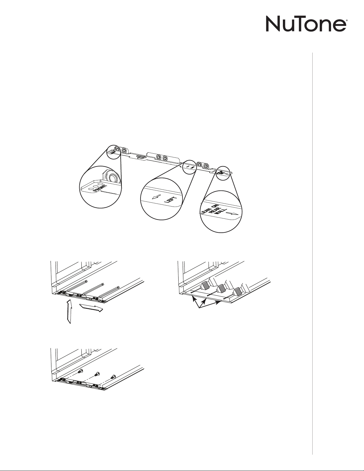
FRAMED CABINET
7/64”
XY
Z
Refer to the marking on brackets to determine the correct installation side and orientation.
Mate the corresponding bracket to the cabinet side frame, while placing rear end
of bracket against the wall. Use a pencil to mark 3 holes (there are 6 holes but only
3 are necessary).
Remove the bracket. Using a 7/64” drill bit, drill 3 holes where marked.
Assemble the bracket to the side frame using a Phillips screwdriver and 3 provided
no. 8 x 5/8” wood screws. Repeat for the other side frame.
7 ] Install the proper installation brackets according to the type of cabinet (framed or frameless).
See below.
4 ] Drill a 1/8” dia. pilot hole for house wiring, at B location on template.
5 ] Use a sharp pencil or 1/8” drill bit to mark the locations for the appropriate duct access
holes (16 locations for 7” round duct, or 4 corner locations for rectangular duct). Remove the
template.
6 ] Draw the border for the exhaust ducting by linking its marks (16 for round duct and 4 for
rectangular duct), then cut the opening in the cabinet bottom (vertical exhaust) or in the wall
(horizontal exhaust). Drill the house wiring hole by using a 1½” hole saw centered with the
pilot hole previously made in 4.
INSTALLATION MANUAL
INSTALLATION
16
[ \
7/64”
X
3 X
Y
Z
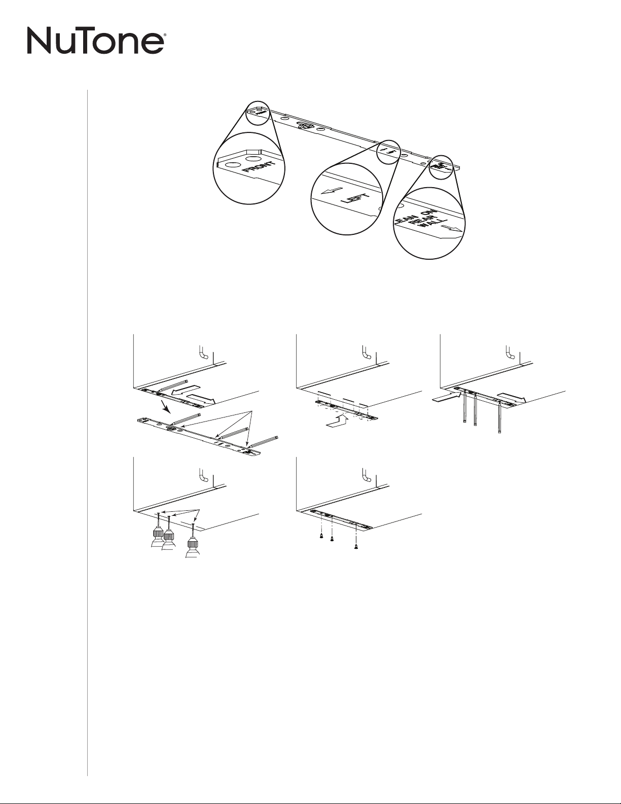
Refer to the marking on brackets to determine the correct installation side and orientation.
Align the corresponding bracket to the cabinet side, while placing rear end of bracket
against the wall. Draw a line on the outer edge of the bracket (as shown).
Slide the bracket towards the center of cabinet and align outside edge of the bracket to
marked line, keeping the rear end edge leaning on the wall.
Use a pencil to mark 3 holes.
Remove the bracket. Using a 7/64” drill bit, drill 3 holes where marked.
Assemble the bracket to the cabinet bottom using a Phillips screwdriver and 3 provided
countersunk wood screws. Repeat for the other cabinet side.
FRAMELESS CABINET

INSTALLATION MANUAL
INSTALLATION
17
A
C
B
D
HORIZONTAL EXHAUST INSTALLATION ONLY
VERTICAL EXHAUST INSTALLATION AND NON-DUCTED INSTALLATION ONLY
OTE: N The following procedure applies to both frame or frameless cabinet installations.
Install the Hood (EZ1 Bracket)
1 ] Run house power cable between service panel and hood location.
2 ] There are 2 pairs of recessed holes on each side of the top of the hood (on rear: A and B,
on front C and D on illustration below); these holes allow the range hood to hang on the
brackets (previously installed).
3 ] Temporarily hang the hood on the brackets using its (2) recessed REAR HOLES (A and B).
While holding the hood, run the house power cable into the hood through the strain relief
previously installed in step 6 on page 11.
4 ] Unhook the rear holes from the brackets and hang the hood using its (2) recessed FRONT
HOLES (C and D). While holding the hood, go to step 6.
5 ] Hang the hood on the brackets using the (2) recessed FRONT HOLES (C and D). While
holding the hood, tighten an appropriate strain relief, 1/2” diameter (not included) to the
power cable, then insert the strain relief in the knockout hole.
6 ] Connect ductwork to hood and use metal foil duct tape to make joints secure and air-tight.
Make sure the damper assembly (or round duct plate) enters the ductwork and that the
damper opens and closes freely.
NOTE: See final installation steps on next page.
A
B
DUCTED INSTALLATION ONLY
INSTALLATION MANUAL
INSTALLATION
18
FRAMED
CABINET
FRAMELESS
CABINET
7 ] For framed cabinet, secure the hood to the EZ1 brackets using four (4) no. 8-18 x 1/2” metal
screws (included in parts bag). Insert two (2) screws per side, in the slots (as shown in insets
on illustration below).
8 ] For frameless cabinet, secure the hood to the cabinet using four (4) no. 8 x 5/8” round head
wood screws (included in parts bag). Insert two (2) screws per side, in the slots (as shown in
inset on illustration below).
9 ] Attach power cable to the hood using the strain relief.
WOOD
SCREWS
METAL
SCREWS
INSTALLATION MANUAL
INSTALLATION
19
Standard Installation (without EZ1 brackets)
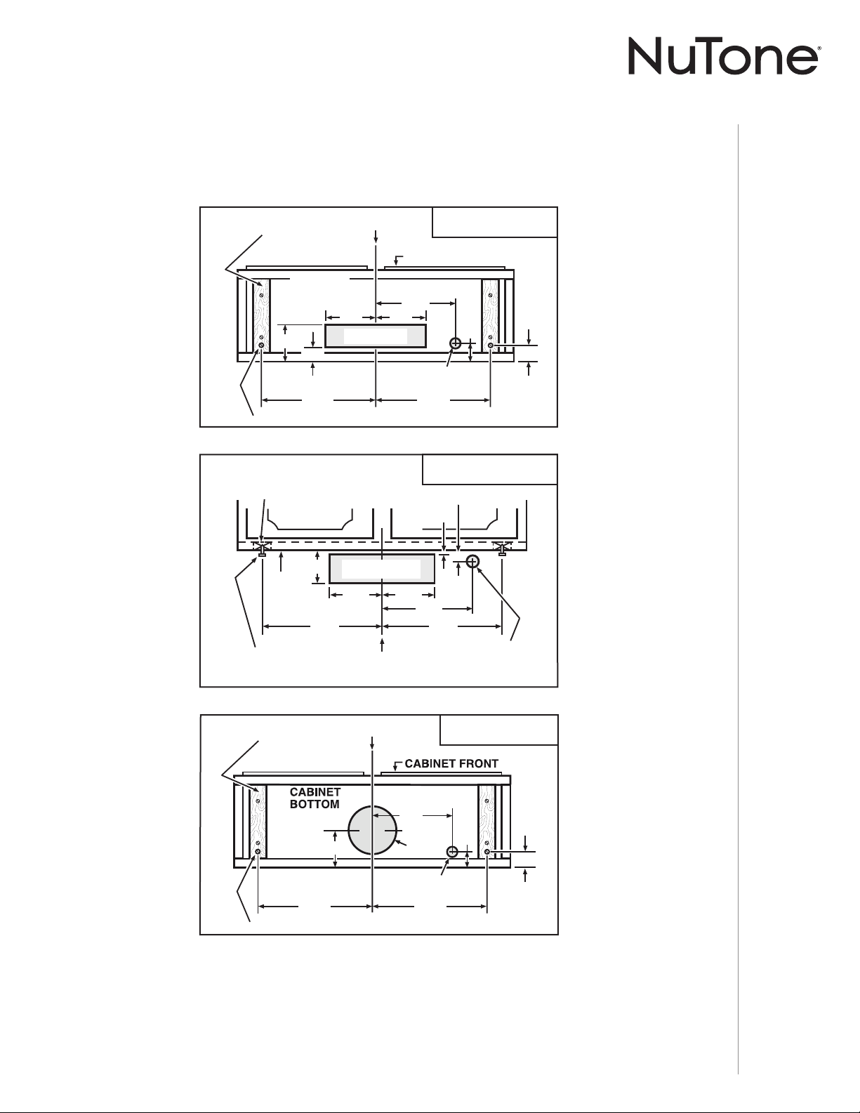
1 ] Use the proper diagram below for placement of ductwork and electrical cutout in cabinet
or wall. For a non-ducted installation, DO NOT cut a duct access hole, only cut the hole for
electrical wiring.
2 ] Install part-way two (2) ROUND HEAD no. 8 x 5/8” mounting screws into shims/cabinet,
according to the proper diagram above, the other 2 ROUND HEAD no. 8 x 5/8” mounting
screws will be used later. (Mounting screws are included in parts bag, but wood shims and
shim mounting screws are not included.)
VERTICAL DUCT
ACCESS HOLE
5¼"
5¼"
CENTER LINE
ELECTRICAL ACCESS
HOLE (
IN CABINET BOTTOM)
WOOD SHIMS
(
RECESSED-BOTTOM
CABINETS
ONLY)
CABINET FRONT
3/4"
1⅜"
1½"
9¾"
12⅞"
4
7
/16"
CABINET
BOTTOM
12⅞"
REAR HOOD MOUNTING SCREWS (2)
3¼" X 10"
VERTICAL DUCTING
CABINET
BOTTOM
CABINET FRONT
HORIZONTAL DUCT
ACCESS HOLE
REAR HOOD
MOUNTING
SCREWS (2)
ELECTRICAL
ACCESS HOLE
(
IN WALL)
3⅞"
CENTER
LINE
WOOD SHIMS
(RECESSED-BOTTOM
CABINETS
ONLY)
13/16"
3/16"
5¼"
5¼"
12⅞"
12⅞"
9¾"
3¼" X 10"
HORIZONTAL DUCTING
4¹¹/16"
8" DIA.
HOLE
7-IN. ROUND
7-IN. ROUND
DUCT
DUCT
ACCESS
ACCESS
HOLE
HOLE
7-IN. ROUND
DUCT
ACCESS
HOLE
1½"
1⅜"
9¾"
CENTER LINE
ELECTRICAL ACCESS
HOLE (
IN CABINET BOTTOM)
12⅞" 12⅞"
REAR HOOD MOUNTING SCREWS (2)
WOOD SHIMS
(
RECESSED-BOTTOM
CABINETS
ONLY)
7-IN. ROUND
VERTICAL DUCTING
INSTALLATION MANUAL
INSTALLATION
20
Install the Hood (Standard Installation)
1 ] Run house power cable between service panel and hood location. For hood with power
cable access located on back of hood, run the house power cable into the hood through
the strain relief previously installed in step 7 on page 11. For hood with power cable access
located on top, tighten the strain relief to the power cable before inserting the strain relief in
the knockout hole.
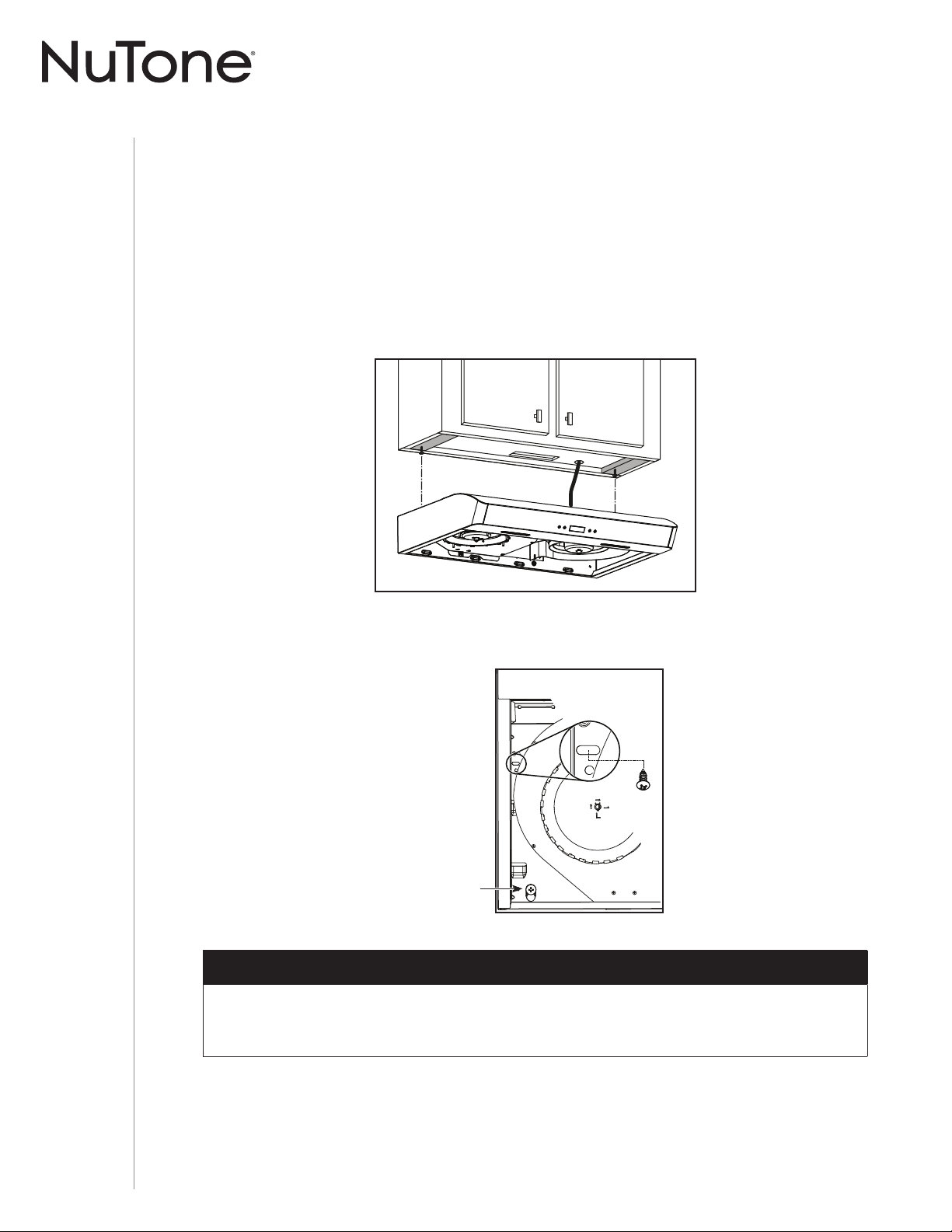
2 ] Hang hood from two (2) rear mounting screws previously installed. Slide hood back towards
wall until mounting screw heads are engaged in narrow end of keyhole slots in top of hood.
Tighten screws securely and maintain a hold on the hood until completing step 3.
3 ] Secure the hood to the cabinet using two (2) no. 8 x 5/8” round head wood screws (included
in parts bag). Insert one (1) screw per side, in the slots (as shown below). Attach power cable
to the hood using the strain relief.
4 ] Connect ductwork to hood and use metal foil duct tape to make joints secure and air-tight.
Make sure the damper assembly (or round duct plate) enters the ductwork and that the damper
opens and closes freely.
DUCTED INSTALLATION ONLY
OTE: N Two installers are recommended because of the weight of this hood.
BACK OF HOOD
Screw previously
tighten in step 2.
INSTALLATION MANUAL
INSTALLATION
21
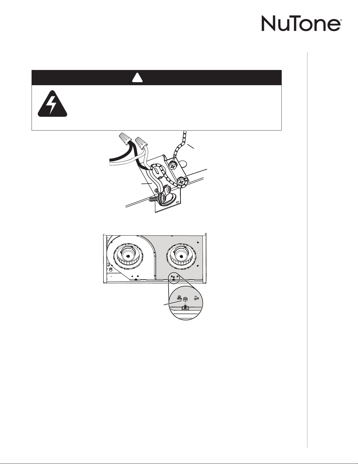
Connect the Wiring
1 ] Connect House Power Cable to range hood wiring: BLACK to BLACK, WHITE to WHITE and
GREEN or bare wire under GREEN ground screw.
2 ] Reinstall the blower cover plate (shaded part on illustration above) using the lock nut and
the 7 screws previously removed in step 4 on page 10. Pay attention to screw 1 location; from
back of hood point of view, it must be located on left side of the lock nut (see inset).
!
WARNING
Risk of electric shock. Electrical wiring must be done by qualifi ed
personnel in accordance with all applicable codes and standards.
Before connecting wires, switch power off at service panel and lock
service disconnecting means to prevent power from being switched
on accidentally.
MOTORS
GROUND
WIRE
HOUSE
POWER CABLE
GROUND
SCREW
1
2
3
45
6
7
Install the Filters
Ducted Installation Only:
Re-install grease filters removed in step 3 , page 10, under “Prepare the Hood”.
Non-ducted Installation Only:
Purchase two non-ducted filters from your local distributor or retailer (see product specification label
for filter type). Attach the non-ducted filters following instructions packed with the non-ducted filters.
BACK OF HOOD
1
LOCK NUT
INSTALLATION MANUAL
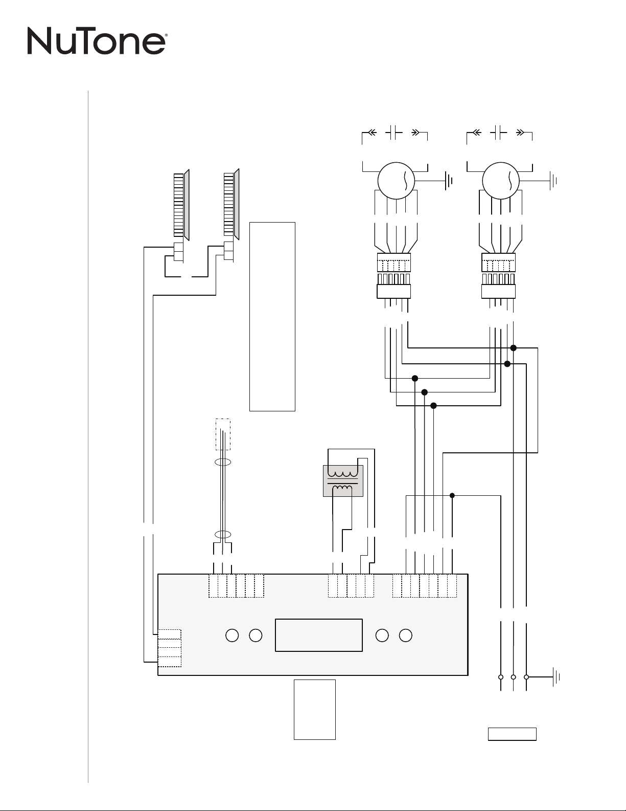
WIRING DIAGRAM
22
BK
G/Y
BK
24 V
Class 2
W
R
BL
BL
R
R
BK (H)
BK
R (L)
O (M)
BK (H)
G/Y
J2
54
1 6
J4
J1
1
2
3
4
5
3
4
5
6
7
1
2
3
2
1
4
LCD INTERFACE
Power, Motor
Transformer
LED
O (M)
O (M)
BK (H)
R (L)
R (L)
G/Y
Control Board
ADA Override
W
W
W
W
Transformer
Heatshrink
W
R
BK
Ref: 990729478A
LED
2 1
LED
2 1
Note: The control
board is viewed with
the connectors on
the opposite side of
the board.
W
R
BK
O
G/Y
1
2
3
5
4
6
W
R
BK
O
G/Y
1
2
3
5
4
6
BK
Line
Neutral
Ground
120 V AC
COLOR CODE
BK
BL
BN
BN/W
BLACK
BLUE
BROWN
BROWN/WHITE
G/Y
O
R
W
GREEN/YELLOW
ORANGE
RED
WHITE
FAN MOTOR
FAN MOTOR
M
M
BN
BN/W
C
BN/W
C
BN
BK
BK
BK
BK
23
J6
AVDN1 SERIES (SECOND GENERATION)
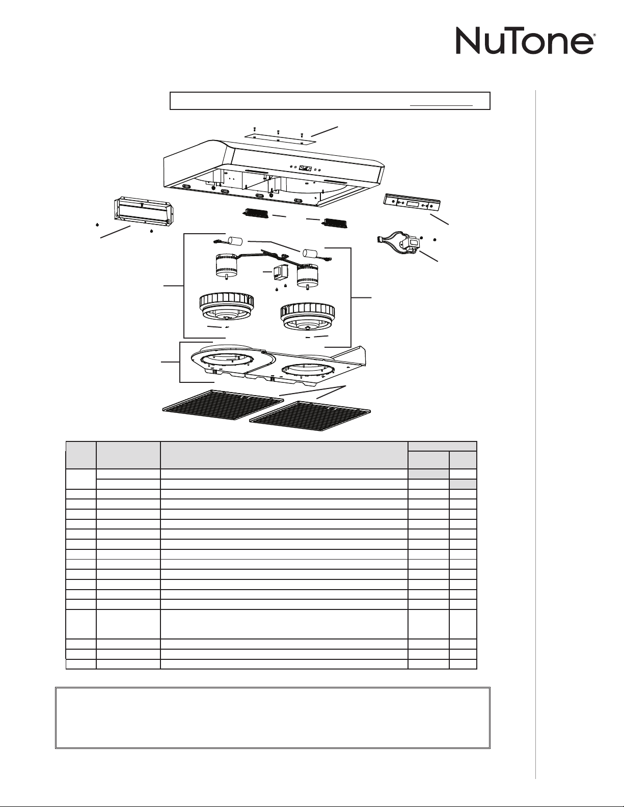
INSTALLATION MANUAL
SERVICE PARTS
23
AVDN1 SERIES
First Generation: Serial number 091810008492 and previous.
* ITEM NOT SHOWN.
B
C
D
E
H
I
K
L
M
F
F
J
KEY NO.PART NO.DESCRIPTION
QUANTITY
30"
STAINLESS
30"
WHITE
1
S97020030 R
ECIRCULATION COVER PLATE, WHITE (INCLUDING SCREWS)1
S97020031 RECIRCULATION COVER PLATE, STAINLESS STEEL (INCLUDING SCREWS)1
2 S97020534 3¼” X 10” DAMPER ASSEMBLY (INCLUDING SCREWS)11
3 S97020412 CAPACITOR (INCLUDING TIE WRAP)22
4 S97020842 B
LOWER ASS’Y CW (INCLUDING ITEMS 3 AND 5 AND HARDWARE)11
5 SR99420635 CLIP FOR FANPELLER 22
6 S97021337 BOTTOM COVERS (WITH INLETS)11
7 S97020204-002 GREASE FILTER - HYBRID -TYPE C5 (SET OF 2) 1 1
8 S97020843 BLOWER ASS’Y CCW (INCLUDING ITEMS 3 AND 5 AND HARDWARE)11
9 S97020797 A
UTOTRANSFORMER (WITH SCREWS)11
10 S97020444 LED MODULES (PAIR)11
11 S97021392 TRANSFORMER KIT, 24 V 18 VA (WITH SCREWS)11
12 S97020459 LCD CONTROL (WITH SCREWS)11
* S97020796 WIRE HARNESS WITH AUTOTRANSFORMER AND FUSE 11
* S97020360
PARTS BAG INCLUDING: 4 METAL SCREWS NO. 8-18 X 1/2”,
6 ROUND HEAD NO. 8 X 5/8” WOOD SCREWS,
6 NO. 8 X 1/2” COUNTERSUNK WOOD SCREWS
11
* S97020466 N
ON-DUCTED FILTER - TYPE XC (SET OF 2) (NON-DUCTED INSTALLATION ONLY)1 1
* S99527587 NON-DUCTED FILTER CLIP KIT (INCLUDES 4 CLIPS)11
* S97020470 EASY INSTALL KIT (INCLUDING HARDWARE)11
G
REPLACEMENT PARTS AND REPAIRS
In order to ensure your unit remains in good working condition, you must use Venmar Ventilation ULC genuine replacement parts
only. Venmar Ventilation ULC genuine replacement parts are specially designed for each unit and are manufactured to comply with
all the applicable certification standards and maintain a high standard of safety. Any third party replacement part used may cause
serious damage and drastically reduce the performance level of your unit, which will result in premature failing. Venmar Ventilation ULC
recommends to contact a certified service depot for all replacement parts and repairs.
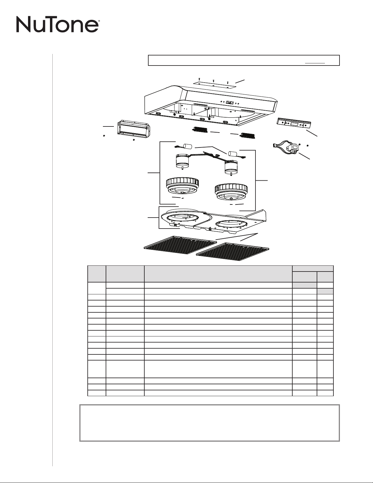
INSTALLATION MANUAL
SERVICE PARTS
24
AVDN1 SERIES
REPLACEMENT PARTS AND REPAIRS
In order to ensure your unit remains in good working condition, you must use Venmar Ventilation ULC genuine replacement parts
only. Venmar Ventilation ULC genuine replacement parts are specially designed for each unit and are manufactured to comply with
all the applicable certification standards and maintain a high standard of safety. Any third party replacement part used may cause
serious damage and drastically reduce the performance level of your unit, which will result in premature failing. Venmar Ventilation ULC
recommends to contact a certified service depot for all replacement parts and repairs.
C
D
E
H
I
J
K
L
F
F
B
G
Second Generation: Serial number 091810008493 and up.
* ITEM NOT SHOWN.
KEY NO.PART NO.DESCRIPTION
QUANTITY
30"
STAINLESS
30"
WHITE
1
S97020030 R
ECIRCULATION COVER PLATE, WHITE (INCLUDING SCREWS)1
S97020031 RECIRCULATION COVER PLATE, STAINLESS STEEL (INCLUDING SCREWS)1
2 S97020534 3¼”
X 10” DAMPER ASSEMBLY (INCLUDING SCREWS)11
3 S97020412 CAPACITOR (INCLUDING TIE WRAP)22
4 S97021326 BLOWER ASS’Y CW (INCLUDING ITEMS 3 AND 5 AND HARDWARE)11
5 SR99420635 CLIP FOR FANPELLER 22
6 S97021339 BOTTOM COVERS (WITH INLETS)11
7 S97020204-002 GREASE FILTER - HYBRID -TYPE C5 (SET OF 2) 1 1
8 S97021327 B
LOWER ASS’Y CCW (INCLUDING ITEMS 3 AND 5 AND HARDWARE)11
9 S97020444 LED MODULES (PAIR)11
10 S97021392 T
RANSFORMER KIT, 24 V 18 VA (WITH SCREWS)11
11 S97020459 LCD C
ONTROL 11
* S97020454 WIRE HARNESS 11
* S97020360
PARTS BAG INCLUDING: 4 METAL SCREWS NO. 8-18 X 1/2”,
6 ROUND HEAD NO. 8 X 5/8” WOOD SCREWS,
6 NO. 8 X 1/2” COUNTERSUNK WOOD SCREWS
11
* S97020466 N
ON-DUCTED FILTER - TYPE XC (SET OF 2) (NON-DUCTED INSTALLATION ONLY)1 1
* S99527587 N
ON-DUCTED FILTER CLIP KIT (INCLUDES 4 CLIPS)11
* S97020470 E
ASY INSTALL KIT (INCLUDING HARDWARE)11

INSTALLATION MANUAL
WARRANTY
25
Limited Warranty
Warranty Period and Exclusions: Venmar Ventilation ULC (the “Company”) warrants to the original consumer purchaser
of its product (“you”) that the product (the “Product”) will be free from material defects in the Product or its workmanship
for a period of one (1) year from the date of original purchase (or such longer period as may be required by applicable law).
For Range Hood Product that includes built-in LED modules, the Company warrants the LED modules and driver to be
free from material defects for a period of three (3) years from the date of purchase. The limited warranty period for any
replacement parts provided by the Company and for any Products repaired or replaced under this limited warranty shall be
the remainder of the original warranty period (or such longer period as may be required by applicable law).
This warranty does not cover fluorescent lamp starters, tubes, halogen and incandescent bulbs, fuses, filters, ducts, roof
caps, wall caps and other accessories for ducting that may be purchased separately and installed with the Product. This
warranty also does not cover (a) normal maintenance and service, (b) normal wear and tear, (c) any Products or parts
which have been subject to misuse, abuse, abnormal usage, negligence, accident, improper or insufficient maintenance,
storage or repair (other than repair by the Company), (d) damage caused by faulty installation, or installation or use contrary
to recommendations or instructions, (e) any Product that has been moved from its original point of installation, (f) damage
caused by environmental or natural elements, (g) damage in transit, (h) natural wear of finish, (i) Products in commercial or
nonresidential use, or (j) damage caused by fire, flood or other act of God or (k) Products with altered, defaced or removed
serial numbers. This warranty covers only Products sold to original consumers in Canada by the Company or its Canadian
distributors authorized by the Company.
This warranty supersedes all prior warranties and, subject to applicable law, is not transferable from the original consumer purchaser.
No Other Warranties: This Limited Warranty contains the Company’s sole obligation and your sole remedy for defective
products. The foregoing warranties are exclusive and in lieu of any other warranties and conditions, express or implied. THE
COMPANY DISCLAIMS AND EXCLUDES ALL OTHER EXPRESS WARRANTIES AND CONDITIONS, AND DISCLAIMS
AND EXCLUDES ALL WARRANTIES AND CONDITIONS IMPLIED BY LAW, INCLUDING WITHOUT LIMITATION
THOSE OF MERCHANTABILITY AND FITNESS FOR A PARTICULAR PURPOSE. To the extent that applicable law
prohibits the exclusion of implied warranties or conditions, the duration of any applicable implied warranty or condition is
limited to the period specified for the express warranty above. Some jurisdictions do not allow limitations on how long an
implied warranty lasts, so the above limitation may not apply to you. Any oral or written description of the Product is for the
sole purpose of identifying it and shall not be construed as an express warranty.
Whenever possible, each provision of this Limited Warranty shall be interpreted in such manner as to be effective and valid
under applicable law, but if any provision is held to be prohibited or invalid, such provision shall be ineffective only to the
extent of such prohibition or invalidity, without invalidating the remainder of such provision or the other remaining provisions
of the Limited Warranty.
Remedy: During the applicable limited warranty period, the Company will, at its option, provide replacement parts for, or
repair or replace, without charge, any Product or part thereof, to the extent the Company finds it to be covered by and in
breach of this limited warranty under normal use and service. The Company will ship the repaired or replaced Product or
replacement parts to you at no charge. You are responsible for all costs for removal, reinstallation and shipping, insurance or
other freight charges incurred in the shipment of the Product or part to the Company. If you must send the Product or part to
the Company, as instructed by the Company, you must properly pack the Product or part—the Company is not responsible
for damage in transit. The Company reserves the right to utilize reconditioned, refurbished, repaired or remanufactured
Products or parts in the warranty repair or replacement process. Such Products and parts will be comparable in function
and performance to an original Product or part and warranted for the remainder of the original warranty period (or such
longer period as may be required by applicable law).
Company reserves the right, in its sole discretion, to refund the money actually paid by you for the Product in lieu of repair or
replacement. If the Product or component is no longer available, replacement may be made with a similar product of equal
or greater value, at Company’s sole discretion. This is your sole and exclusive remedy for breach of this limited warranty.
Exclusion of Damages: THE COMPANY’S OBLIGATION TO PROVIDE REPLACEMENT PARTS, OR REPAIR,
REPLACE OR REFUND, AT THE COMPANY’S OPTION, SHALL BE YOUR SOLE AND EXCLUSIVE REMEDY UNDER
THIS LIMITED WARRANTY AND THE COMPANY’S SOLE AND EXCLUSIVE OBLIGATION. THE COMPANY SHALL
NOT BE LIABLE FOR INCIDENTAL, INDIRECT, CONSEQUENTIAL OR SPECIAL DAMAGES ARISING OUT OF OR IN
CONNECTION WITH THE PRODUCT, ITS USE OR PERFORMANCE. Incidental damages include but are not limited to
such damages as loss of time and loss of use. Consequential damages include but are not limited to the cost of repairing
or replacing other property which was damaged if the Product does not work properly.
THE COMPANY SHALL NOT BE LIABLE TO YOU, OR TO ANYONE CLAIMING UNDER YOU, FOR ANY OTHER
OBLIGATIONS OR LIABILITIES, INCLUDING, BUT NOT LIMITED TO, OBLIGATIONS OR LIABILITIES ARISING
OUT OF BREACH OF CONTRACT OR WARRANTY, NEGLIGENCE OR OTHER TORT OR ANY THEORY OF STRICT
LIABILITY, WITH RESPECT TO THE PRODUCT OR THE COMPANY’S ACTS OR OMISSIONS OR OTHERWISE.
Some jurisdictions do not allow the exclusion or limitation of incidental or consequential damages, so the above limitation
or exclusion may not apply to you. This warranty gives you specific legal rights, and you may also have other rights, which
vary from jurisdiction to jurisdiction. The disclaimers, exclusions, and limitations of liability under this warranty will not apply
to the extent prohibited by applicable law.
This warranty covers only replacement or repair of defective Products or parts thereof at the Company’s main facility and
does not include the cost of field service travel and living expenses.
Any assistance the Company provides to or procures for you outside the terms, limitations or exclusions of this limited warranty
will not constitute a waiver of such terms, limitations or exclusions, nor will such assistance extend or revive the warranty.
The Company will not reimburse you for any expenses incurred by you in repairing or replacing any defective Product,
except for those incurred with the Company’s prior written permission.
How to Obtain Warranty Service: To qualify for warranty service, you must (a) notify the Company at the address or
telephone number stated below within seven (7) days of discovering the covered defect, (b) give the model number and
part identification and (c) describe the nature of any defect in the Product or part. At the time of requesting warranty
service, you must present evidence of the original purchase date. If you cannot provide a copy of the original written
limited warranty, then the terms of the Company’s most current written limited warranty for your particular product
will control. The most current limited written warranties for the Company’s products can be found at www.nutone.ca.
Venmar Ventilation ULC, 550 Lemire Blvd., Drummondville, Québec, Canada J2C 7W9
www.nutone.ca 1-877-896-1119
WWW.NUTONE.CA
Numéro de série :
99045654-001J
HOTTE
DE CUISINIÈRE
Série : AVDN1
MANUEL D’INSTALLATION,
D’UTILISATION ET D’ENTRETIEN
WWW.NUTON

MANUEL D’INSTALLATION
TABLE DES MATIÈRES
22
Sécurité . . . . . . . . . . . . . . . . . . . . . . . . . . . . . . . 3-4
Fonctionnement . . . . . . . . . . . . . . . . . . . . . . . . . 5-6
Nettoyage et entretien . . . . . . . . . . . . . . . . . . . . . 7
Moteurs
Filtres à graisses
Filtres de recirculation
Roues de ventilateur
Nettoyage de l’acier inoxydable
Nettoyage des surfaces peintes
Installation . . . . . . . . . . . . . . . . . . . . . . . . . . . . 8-21
Outils et accessoires recommandés
pour l’installation . . . . . . . . . . . . . . . . . . . . . . . . 8
Installation des conduits
(installations avec conduits seulement) . . . . . . 8
Contenu . . . . . . . . . . . . . . . . . . . . . . . . . . . . . . 9
Préparation de la hotte . . . . . . . . . . . . . . . . . . . 10-13
Préparation de l’emplacement de la hotte . . . . . 14
Système d’installation par une personne EZ1 14-16
Installation de la hotte (avec supports EZ1) . . 17-18
Installation standard . . . . . . . . . . . . . . . . . . . . 19
Installation de la hotte (installation standard) . 20
Branchement électrique . . . . . . . . . . . . . . . . . . 21
Installation des filtres . . . . . . . . . . . . . . . . . . . . 21
Schéma électrique . . . . . . . . . . . . . . . . . . . . . . . 22
Pièces de rechange . . . . . . . . . . . . . . . . . . . . 23-24
Garantie . . . . . . . . . . . . . . . . . . . . . . . . . . . . . . . 25
MANUEL D’INSTALLATION
SÉCURITÉ
3
!
AVERTISSEMENT
AFIN DE RÉDUIRE LES RISQUES D’INCENDIE, D’ÉLECTROCUTION OU
DE BLESSURES CORPORELLES, SUIVEZ LES DIRECTIVES SUIVANTES :
• N’utilisez cet appareil que de la façon prévue par le manufacturier. Si vous
avez des questions, contactez le manufacturier à l’adresse ou au numéro
de téléphone indiqués dans la garantie.
• Avant de réparer ou de nettoyer l’appareil, couper l’alimentation électrique
en verrouillant le panneau de distribution afin d’éviter sa remise en marche
accidentelle. Si le panneau de distribution ne peut être verrouillé, y fixer un
avertissement en évidence, telle qu’une étiquette de couleur vive.
• Les travaux d’installation et de raccordement électrique doivent être
effectués par une personne qualifiée, conformément aux codes et aux
standards de construction, incluant ceux concernant la protection contre
les incendies.
• Une quantité d’air adéquate est requise afin d’assurer une bonne
combustion et l’évacuation des gaz par la cheminée dans le cas des
équipements alimentés au gaz afin de prévenir les retours de cheminée.
Conformez-vous aux instructions et aux standards de sécurité des
manufacturiers d’équipement de chauffage, tel qu’ils sont publiés par
la National Fire Protection Association (NFPA) et l’American Society for
Heating, Refrigeration and Air Conditioning Engineers (ASHRAE) ainsi
que les responsables des codes locaux.
• Veillez à ne pas endommager le câblage électrique ou d’autres équipements
non apparents lors de la découpe ou du perçage du mur ou du plafond.
• Les ventilateurs avec conduits doivent toujours évacuer l’air à l’extérieur.
• Ne pas utiliser cet appareil avec une commande de vitesse à
semi-conducteur additionnelle.
• Afin de réduire les risques d’incendie, n’utilisez que des conduits de métal.
• Cet appareil doit être mis à la terre.
• Si désiré, ce produit peut être installé avec l’ensemble de cordon
d’alimentation homologué par UL spécialement conçu pour ce produit, en
suivant les directives incluses avec le cordon.
• Lorsqu’une réglementation est en vigueur et qu’elle comporte des
exigences d’installation et/ou de certification plus restrictives, lesdites
exigences prévalent sur celles de ce document et l’installateur entend s’y
conformer à ses frais.
VEUILLEZ LIRE ET CONSERVER CES DIRECTIVES
!
Conçues pour usage domestique seulement
!
INSTALLATEUR : LAISSER CE MANUEL AU PROPRIÉTAIRE.
Enregistrez votre hotte en ligne à www.nutone.ca
MANUEL D’INSTALLATION
SÉCURITÉ
4
!
AVERTISSEMENT
AFIN DE RÉDUIRE LES RISQUES DE FEU DE CUISINIÈRE :
a) Ne jamais laisser les appareils de cuisson sans surveillance lorsqu’ils sont
réglés à feu vif. Les débordements engendrent de la fumée et des déversements
graisseux pouvant s’enflammer. Chauffez l’huile lentement, à feu doux ou moyen.
b) Mettez toujours la hotte en marche lorsque vous cuisinez à feu vif ou que vous
cuisinez des mets flambés (par ex. : crêpes Suzette, cerises jubilé, steaks au
poivre flambés).
c) Nettoyez régulièrement l’hélice du ventilateur. Ne laissez pas la graisse
s’accumuler sur le ventilateur, le filtre ou les conduits d’évacuation.
d) Utilisez le bon format de casserole. Servez-vous toujours de casseroles et
d’ustensiles appropriés à la dimension de la surface chauffante.
AFIN DE RÉDUIRE TOUT RISQUE DE BLESSURES LORS D’UN FEU DE
CUISINIÈRE, SUIVEZ CES DIRECTIVES* :
1. ÉTOUFFEZ LES FLAMMES avec un couvercle hermétique, une tôle à
biscuits ou un plateau métallique et ensuite, éteignez le brûleur. PRENEZ
SOIN D’ÉVITER LES BRÛLURES. SI LES FLAMMES NE S’ÉTEIGNENT PAS
IMMÉDIATEMENT, ÉVACUEZ LES LIEUX ET APPELEZ LES POMPIERS.
2. NE PRENEZ JAMAIS UNE CASSEROLE EN FLAMMES DANS VOS MAINS.
Vous pourriez vous brûler.
3. N’UTILISEZ PAS D’EAU, incluant un linge à vaisselle ou une serviette mouillée,
cela pourrait occasionner une violente explosion de vapeur.
4. N’utilisez un extincteur QUE DANS LE CAS OÙ :
A. Vous possédez un extincteur de classe ABC et vous en connaissez le
fonctionnement.
B. Le feu est petit et limité à l’endroit où il a débuté.
C. Les pompiers ont été avisés.
D. Vous pouvez combattre le feu en ayant accès à une sortie de secours.
* Tirées du Kitchen Fire Safety Tips publié par la NFPA.
!
ATTENTION
• Pour une utilisation à l’intérieur seulement.
• Pour usage domestique seulement. Ne pas utiliser pour évacuer des vapeurs ou des matières
dangereuses ou explosives.
• Afin d’éviter tout dommage au moteur et de débalancer ou de rendre bruyante l’hélice du moteur,
garder votre appareil à l’abri des poussières de gypse et de construction/rénovation, etc.
• Le moteur de votre hotte possède une protection thermique qui éteindra automatiquement le
moteur s’il devient surchauffé. Le moteur redémarrera automatiquement une fois refroidi. Si le
moteur continue à arrêter et à redémarrer, faites-le vérifier.
• Pour une meilleure évacuation des odeurs de cuisson, le bas de votre hotte devrait être situé À UN
MINIMUM de 18 po et à un maximum de 30 po au-dessus de la surface de cuisson.
• Toujours suivre les recommandations du manufacturier de l’appareil de cuisson concernant les
exigences de cet appareil en matière de ventilation.
• Afin de réduire les risques d’incendie et évacuer l’air adéquatement, assurez-vous que les conduits
évacuent l’air à l’extérieur. Ne pas évacuer l’air dans des espaces restreints comme l’intérieur des
murs ou plafond ou dans le grenier, faux plafond ou garage.
• Il est recommandé de porter des lunettes et des gants de sécurité lors de l’installation, de l’entretien
ou de la réparation de cet appareil.
• Veuillez consulter l’autocollant apposé à l’intérieur de la hotte pour plus d’information ou autres
exigences.
MANUEL D’INSTALLATION
FONCTIONNEMENT
5
Fonctionnement
Toujours mettre en marche la hotte avant de commencer la cuisson afin d’établir une circulation
d’air dans la cuisine. Laisser également la hotte fonctionner quelques minutes après l’arrêt de la
cuisinière afin de nettoyer l’air. Cela aidera à maintenir la cuisine plus propre et plus fraîche.
Faire fonctionner la hotte comme suit :
ACTIVATION DES VENTILATEURS/CHANGEMENT DE VITESSE/MISE À ZÉRO DE
L’INDICATEUR DES FILTRES
Lorsque les ventilateurs sont en ARRÊT, appuyer sur ce bouton pour les ACTIVER à la dernière
vitesse mémorisée. Si aucune vitesse n’est mémorisée, les ventilateurs s’activeront en BASSE
vitesse.
NOTE : Si la basse vitesse est activée lorsque les ventilateurs sont en ARRÊT, les ventilateurs
démarrent en vitesse MOYENNE pour un très court laps de temps, puis se règlent en
BASSE vitesse.
Pour changer la vitesse des ventilateurs, appuyer encore une fois sur ce bouton jusqu’à l’atteinte
de la vitesse désirée (de BASSE, à MOYENNE, à HAUTE, à ARRÊT). À chaque fois qu’une vitesse
de ventilateur est activée, l’icône du ventilateur apparaît à gauche de l’écran avec un ou des points
sous celle-ci; cette icône tourne selon la vitesse choisie (lentement pour la BASSE vitesse avec un
point, plus rapidement pour la MOYENNE vitesse avec 2 points et encore plus rapidement pour la
HAUTE vitesse, avec 3 points).
Lorsque les ventilateurs sont activés (peu importe la vitesse), appuyer et maintenir la pression
jusqu’à ce que l’icône du ventilateur disparaisse de l’écran; ceci aura pour effet d’arrêter le
fonctionnement des ventilateurs et de mémoriser la vitesse choisie.
Heat Sentry
MC
Cette hotte est munie d’un dispositif de protection qui active les ventilateurs lorsqu’un niveau
anormalement élevé de chaleur est détecté lorsqu’ils sont en fonction. Lors de l’activation du Heat
Sentry, ce dispositif prend le contrôle des ventilateurs et les règle en vitesse MOYENNE tandis
que tous les points sous l’icône du ventilateur clignotent. Cependant, l’éclairage peut encore être
contrôlé. Les ventilateurs demeureront en vitesse MOYENNE jusqu’à ce que la chaleur redevienne
normale, ils retourneront à la vitesse de fonctionnement précédemment choisie.
NOTE : Lorsqu’une chaleur excessive est détectée, le Heat Sentry arrête les deux moteurs et
éteint l’éclairage tandis que tous les points sous l’icône du ventilateur clignotent plus vite.
Autant le fonctionnement de l’éclairage que celui des ventilateurs seront arrêtés jusqu’à
ce que la température ambiante se refroidisse; alors les ventilateurs s’activeront en vitesse
MOYENNE (l’éclairage pourra être contrôlé à nouveau). Les ventilateurs demeureront en
vitesse MOYENNE jusqu’à ce que la température redevienne normale; ils retourneront à
la vitesse de fonctionnement précédemment choisie.
NOTE : Il est normal qu’au démarrage de la hotte ou qu’après une panne de courant, une petite
icône (1) apparaîsse furtivement (durant ± 2 secondes) à l’écran.
RAPPEL DE L’ENTRETIEN DES FILTRES
Lorsqu’il est temps d’effectuer le nettoyage de la hotte et de ses filtres, cette icône apparaît à
l’écran 30 secondes après l’ARRÊT des ventilateurs (voir la section Nettoyage et entretien en
page 7). Ceci se produit à chaque fois que les ventilateurs sont ARRÊTÉS jusqu’à ce que le
rappel de l’entretien des filtres soit remis à zéro. Une fois le nettoyage effectué, faire la mise à zéro
du rappel d’entretien des filtres en appuyant sur le bouton d’activation des ventilateurs durant 3
secondes lors de l’apparition des 30 secondes de l’icône à l’écran.
1

MANUEL D’INSTALLATION
FONCTIONNEMENT
6
ÉCLAIRAGE/MODIFICATION DE L’INTENSITÉ D’ÉCLAIRAGE
Appuyer sur ce bouton pour allumer les lumières à la dernière intensité d’éclairage mémorisée;
l’icône de l’éclairage apparaît à droite de l’écran et le nombre de points affichés sous cette icône
correspond à l’intensité d’éclairage (un point pour BASSE, deux points pour MOYENNE et trois
points pour HAUTE).
Pour modifier l’intensité de l’éclairage, appuyer sur ce bouton jusqu’à l’atteinte de l’intensité désirée
(à partir de la HAUTE intensité, appuyer une autre fois pour éteindre les lumières).
Lorsque les lumières sont allumées (peu importe l’intensité), appuyer et maintenir la pression
jusqu’à ce que l’icône de l’éclairage disparaisse de l’écran; ceci aura pour effet d’éteindre les
lumières et de mémoriser l’intensité d’éclairage choisie.
Cette hotte est munie de modules DEL offrant un éclairage brillant, issus de la plus récente
technologie en matière d’éclairage de surface de cuisson et spécialement conçus pour fonctionner
dans un environnement à chaleur élevée. Leur durabilité est jusqu’à 25 fois supérieure à celle
d’ampoules standards et ils sont plus robustes que les ampoules à DEL typiques.
MARCHE/ARRÊT PRINCIPAL
Appuyer sur ce bouton pour allumer les lumières et activer les ventilateurs aux derniers réglages
mémorisés. Lorsque l’éclairage est allumé et/ou les ventilateurs sont en fonction, appuyer sur ce
bouton pour mémoriser la vitesse actuelle des ventilateurs et l’intensité d’éclairage avant d’éteindre
les lumières et d’arrêter les ventilateurs.
ARRÊT DIFFÉRÉ
Lorsque les ventilateurs FONCTIONNENT, appuyer sur ce bouton pour activer la fonction d’arrêt
différé. Cette icône apparaît à l’écran à côté de l’icône des ventilateurs pour indiquer que la
fonction est activée. Les ventilateurs continueront de fonctionner pour 10 minutes puis s’arrêteront
automatiquement (les deux icônes disparaîtront de l’écran). Lorsque l’arrêt différé est activé, il
est possible de modifier la vitesse des ventilateurs (en utilisant le bouton des ventilateurs) sans
affecter la durée du cycle d’arrêt différé.
Pour annuler la fonction d’arrêt différé avant la fin du cycle de 10 minutes, appuyer une autre fois
sur ce bouton.

MANUEL D’INSTALLATION
NETTOYAGE ET ENTRETIEN
7
Nettoyage et entretien
L’entretien adéquat de la hotte préservera ses performances.
MOTEURS
Les moteurs sont lubrifiés en permanence et n’ont pas besoin d’être huilés. Si les roulements de
moteur sont anormalement bruyants, remplacer le moteur uniquement par le même modèle. La
roue du ventilateur doit aussi être remplacée.
FILTRES À GRAISSES
Les filtres à graisses doivent être nettoyés fréquemment. Utiliser une solution d’eau chaude et de
détergent.
Nettoyer les filtres fabriqués entièrement de métal à l’aide d’un détergent sans phosphate.
L’utilisation d’un détergent avec phosphates ainsi que les conditions locales de l’eau peuvent
entraîner une décoloration des filtres, sans toutefois affecter leur performance. Cette décoloration
n’est pas couverte par la garantie.
FILTRES DE RECIRCULATION
Les filtres de recirculation devraient être remplacés tous les 3 à 6 mois. Remplacer plus souvent
si vos habitudes de cuisson génèrent plus de graisses, comme par exemple la friture ou les
aliments sautés au wok. Voir les directives d’installation incluses avec les filtres de recirculation.
ROUES DE VENTILATEUR
Le centre des roues de ventilateur doit être nettoyé fréquemment. Utiliser un chiffon propre imbibé
d’une solution d’eau chaude et de détergent.
NETTOYAGE DE L’ACIER INOXYDABLE
À faire :
• Laver régulièrement les surfaces à l’aide d’un chiffon propre imbibé d’eau chaude et de
savon doux ou de détergent liquide à vaisselle.
• Toujours nettoyer dans le sens du polissage.
• Toujours bien rincer avec de l’eau claire (2 à 3 fois) et essuyer complètement.
• Un nettoyant domestique conçu spécialement pour l’acier inoxydable peut aussi être utilisé.
À ne pas faire :
• Ne pas utiliser de laine d’acier ou d’acier inoxydable ou tout autre grattoir pour enlever la
saleté tenace.
• Ne pas utiliser une poudre nettoyante abrasive ou rugueuse.
• Ne pas laisser la saleté s’accumuler.
• Ne pas laisser la poussière de plâtre ou tout autre résidu de construction atteindre la hotte.
Couvrir la hotte pour la durée des travaux afin de s’assurer qu’aucune poussière n’atteigne la hotte.
À éviter lors du choix du détergent :
• Tous produits nettoyants contenant des agents de blanchiment; ils attaqueront l’acier inoxydable.
• Tous produits contenant du chlorure, du fluorure, de l’iode ou du bromure; ils détérioreront
rapidement les surfaces.
• Tous produits combustibles utilisés pour le nettoyage : acétone, alcool, éther, benzène, etc.;
ils sont grandement explosifs et ne devraient jamais être utilisés près d’une cuisinière.
NETTOYAGE DES SURFACES PEINTES :
Nettoyer avec de l’eau chaude additionnée de détergent doux seulement. S’il y a décoloration,
utiliser une bonne cire telle qu’une cire automobile. (NE PAS utiliser de nettoyant abrasif ou de
nettoyant à porcelaine.)
MANUEL D’INSTALLATION
INSTALLATION
8
Outils et accessoires recommandés pour l’installation
• Ruban à mesurer
• Tournevis Phillips n° 2
• Tourne-écrou ou douille de 11/32 po
• Tournevis à lame plate (pour dégager les ouvertures préamorcées)
• Perceuse, foret de 1/8 po et scie cloche de 1½ po (pour marquer les repères des trous pour
les conduits et découper le trou pour le passage du fil d’alimentation électrique)
• Foret de 7/64 po (pour percer les trous des vis de montage des supports EZ1)
• Cales de bois (2) et vis à bois (4) (requises pour une installation sous une armoire à fond en retrait)
• Plaque pour conduit rond de 7 po, non incluse (pour conduit rond vertical de 7 po rond,
pièce n° : SR680508)
• Scie (pour la découpe des trous d’une installation avec conduits)
• Cisailles à tôle (installation avec conduits, pour l’ajustement de ceux-ci)
• Pinces (installation avec conduits, pour l’ajustement de ceux-ci)
• Ruban adhésif de métal (installation avec conduits)
• Ciseaux (pour couper le ruban adhésif de métal)
• Crayon
• Pince à dénuder
• Serre-fils de 1/2 po de diamètre (pour fixer le câble d’alimentation électrique de la maison à la hotte)
• Volet BP87Q (nécessaire si des conduits de 7 po ronds sont utilisés)
Installation des conduits
(installations avec conduits seulement)
NOTE : Une distance supérieure à 30 po demeure à la discrétion de l’installateur et de l’utilisateur.
1 ] Déterminer si l’évacuation se fera verticalement (3¼ po x 10 po ou 7 po rond),
ou horizontalement (3¼ po x 10 po seulement).
2 ] Établir où le conduit passera entre la hotte et l’extérieur.
3 ] Un conduit droit et court permettra à votre hotte de fonctionner plus efficacement. Un conduit
long avec des coudes et des transitions réduira la performance de votre hotte. En utiliser le
moins possible. Si possible, utiliser un conduit droit d’au moins 2 pieds avant d’installer un
coude. Pour une grande distance, un conduit d’évacuation de l’air au diamètre plus grand peut
être requis pour obtenir une meilleure performance.
NOTE : Pour utiliser des conduits ronds de 6 po, installer une transition de 3¼ po x 10 po à 6 po
rond (non incluse). Les performances pourraient être affectées.
4 ] Installer un capuchon de toit ou de mur (vendus séparément). Relier le conduit en métal au
capuchon, puis acheminer le conduit jusqu’à l’emplacement de la hotte. Sceller hermétiquement
les raccords à l’aide de ruban adhésif de métal de 2 po de largeur.
Pour connaître les lignes directrices de l’ADA (Americans with Disabilities Act) concernant
l’installation, veuillez entrer votre numéro de modèle dans notre site Internet.
SOFFITE
DE 18 PO MIN. À 30 PO MAX.
AU-DESSUS DE LA SURFACE DE CUISSON
ARMOIRE
CONDUIT DE 3¼ PO X 10 PO
(POUR ÉVACUATION HORIZONTALE)
CAPUCHON DE MUR
CAPUCHON DE TOIT
CONDUIT DE 3¼ PO X 10 PO
OU
7 PO ROND
(POUR ÉVACUATION VERTICALE)
CÂBLAGE DOMESTIQUE
(DESSUS OU ARRIÈRE
DE
LA HOTTE)
HOTTE
MANUEL D’INSTALLATION
INSTALLATION
9
Contenu
Avant de procéder à l’installation, vérifier le contenu de la boîte. Si des articles sont manquants
ou endommagés, contacter le manufacturier.
S’assurer que les articles suivants sont inclus :
C
L
AB
Apoyar este borde contra la pared de atrásPlace this edge against back wall
VERTICAL EXHAUST
S
A
A
V
RTICAL EX
= 3¼” x 10”
= 3¼” x 14”
RECTANGULAR DUCTING7” ROUND DUCTING
OR
Use this template for marking;do not attempt to cut out the ducting hole through it.
NOTE: These cutouts are clearance holes; they do not need to be the exact size of ducting.
= 3¼ po x 10 po
= 3¼ po x 14 po
CONDUIT RECTANGULAIRECONDUIT ROND DE 7 PO
OU
= 3¼ pulg. x 10 pulg.
= 3¼ pulg. x 14 pulg.
CONDUCTO RECTANGULARCONDUCTO REDONDO
DE
7 PULG.
O
Appuyer ce bord au mur arrière
Utiliser ce gabarit pour marquer vos repères;ne pas tenter de découper
le trou pour le conduit à travers le gabarit.
NOTE : Les découpes incluent le jeu nécessaire à l’installation; elles ne doivent pas
être du format exact des conduits.
Use esta plantilla para crear marcados;no trate de cortar el
agujero del conducto a través de la plantilla.
NOTA: To be translated in Spanish.
MARK WHERE INDICATED
FOR THE APPROPRIATE SIZE DUCT OPENING
MARQUER LES REPÈRES AUX ENDROITS INDIQUÉS SELON
LE FORMAT DE CONDUIT UTILISÉ
TITLE TO BE TRANSLATED IN SPANISH
Electrical access hole center
A = single blower hood
B = double blower hood
Centre du trou pour fil
d’alimentation électrique
A = hotte ventilateur simple
B = hotte ventilateur double
To be translated in Spanish
Electrical access hole center
A = single blower hood
B = double blower hood
4¼”
10½”
14½”
8”
7½”
C
C
C
Bend template along graduated
scale when installing to framed
cabinet.
Pour une installation sous une
armoire à fond en retrait, utiliser les
lignes pour mesurer l’épaisseur du
décalage causé par le mur de
l’armoire et plier le gabarit en
conséquence.
To be translated in Spanish.
(1) ADAPTATEUR/VOLET
DE
3¼ PO X 10 PO
(2) S
UPPORTS D’INSTALLATION*
POUR ARMOIRE
AVEC
FOND EN RETRAIT
(2) SUPPORTS D’INSTALLATION*
POUR ARMOIRE AVEC FOND RÉGULIER
(1) GABARIT POUR CONDUITS
(IMPRIMÉ SUR LES DEUX CÔTÉS)
C
OMPOSANTS EZ1
* LES SUPPORTS D’INSTALLATION EZ1 SONT FIXÉS À L’INTÉRIEUR DE LA HOTTE.
(1) SAC DE PIÈCES** COMPRENANT :
(6) V
IS À BOIS
À
TÊTE RONDE
N
° 8 X 5/8 PO
(4) VIS À MÉTAUX
N
° 8-18 X 1/2 PO
(6) VIS À BOIS
À
TÊTE FRAISÉE
N
° 8 X 1/2 PO
(2) F
ILTRES À GRAISSES
** LE SAC DE PIÈCES SE TROUVE À L’INTÉRIEUR DE LA HOTTE.
MANUEL D’INSTALLATION
INSTALLATION
10
B
C
Préparation de la hotte
1 ] Retirer toute présence de pellicule de plastique protectrice sur la hotte et/ou ses pièces.
2 ] Retirer les deux vis du dessus de la hotte. Retirer l’adaptateur/volet du dos de la hotte (voir
l’illustration ci-dessous). Garder les vis pour usage ultérieur.
3 ] Enlever les filtres à graisses en insérant un doigt dans la prise concave de chaque filtre à
graisses puis en poussant vers l’arrière de la hotte et en les basculant .
1
2
3
45
6
7
4 ] À l’aide d’un tourne-écrou ou d’un douille de 11/32 po, retirer l’écrou retenant le rebord du
couvercle du ventilateur de droite (en gris dans l’illustration ci-dessous) à l’arrière de la hotte,
à l’intérieur (voir le médaillon). Retirer les 7 vis de retenue du couvercle puis le mettre de
côté avec son écrou et ses vis.
ARRIÈRE DE
LA HOTTE
ÉCROU
2 VIS
2 VIS
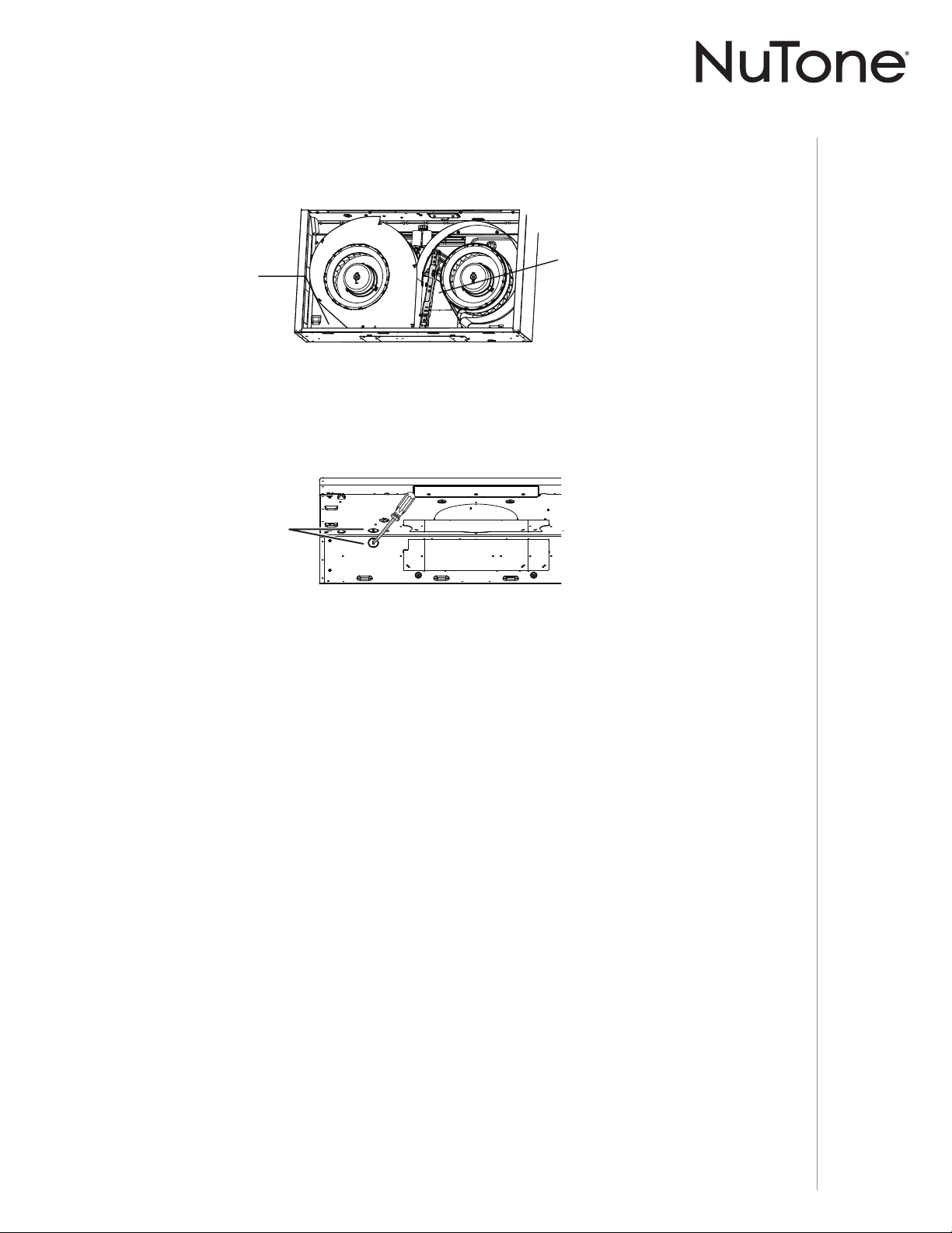
MANUEL D’INSTALLATION
INSTALLATION
11
6 ] Retirer l’ouverture préamorcée du câble d’alimentation électrique du dessus (câblage
vertical) ou de l’arrière de la hotte (câblage horizontal). Pour une ouverture préamorcée
retirée de l’arrière de la hotte, installer un serre-fils approprié de 1/2 po de diamètre (non
inclus). Pour une ouverture préamorcée retirée du dessus de la hotte, le serre-fils sera
installé plus tard.
OUVERTURE PRÉAMORCÉE
DU CÂBLE D’ALIMENTATION
ÉLECTRIQUE
5 ] Retirer le sac de pièces fixé au dos interne de la hotte avec du ruban adhésif, et détacher les
supports EZ1 de l’intérieur de la hotte en coupant leur attache autobloquante. Se défaire de
l’attache autobloquante.
SUPPORTS EZ1
EMPLACEMENT
DU SAC DE PIÈCES

MANUEL D’INSTALLATION
INSTALLATION
12
7 ] Retirer les 3 vis retenant la plaque couvrant la grille de recirculation (en gris dans
l’illustration ci-dessous) à la hotte. Se défaire de cette plaque et de ses vis.
8 ] Soulever et se défaire de la membrane recouvrant la grille de recirculation, en
s’assurant que les ouvertures soient complètement dégagées.
PLAQUE
VIS
INSTALLATION EN RECIRCULATION SEULEMENT
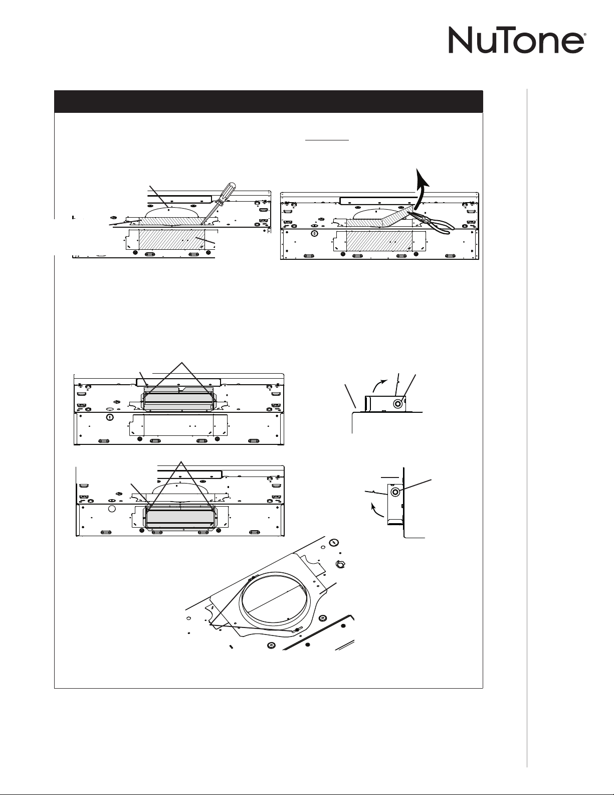
MANUEL D’INSTALLATION
INSTALLATION
13
PLAQUE POUR
CONDUIT ROND
DE 7 PO
INSTALLATION AVEC CONDUITS SEULEMENT
TRUC : Glisser une petite longueur de conduit par dessus l’adaptateur/volet de 3¼ po x 10 po
(pour un conduit rectangulaire) ou de 7 po rond (pour un conduit rond) et sceller le joint à
l’aide de ruban adhésif d’aluminium pour faciliter le raccord avec le reste des conduits.
9 ] Retirer les ouvertures préamorcées de 3¼ po x 10 po verticale, 3¼ po x 10 po
horizontale (les 2 étant les plaques rectangulaires centrales, voir les zones hachurées),
ou 7 po ronde selon le mode d’évacuation choisi (voir les FIGURES 1 A et 1 B).
NOTE : La plaque pour conduit rond de 7 po peut être glissée latéralement, jusqu’à 1/2 po
de chaque côté, pour s’ajuster à un conduit décentré.
OUVERTURE
PRÉAMORCÉE DE 7 PO
RONDE (RETIRER AUSSI
L’OUVERTURE PRÉAMORCÉE
VERTICALE)
OUVERTURE
PRÉAMORCÉE
VERTICALE DE
3¼ PO X 10 PO
FIGURE 1 A
VIS
FIGURE 3
FIGURE 1 B
OUVERTURE
PRÉAMORCÉE
HORIZONTALE
DE 3¼ PO X 10 PO
10 ] Installer l’adaptateur/volet de 3¼ po x 10 po sur le dessus OU à l’arrière de la hotte (en gris
dans la FIGURE 2 A ci-dessous; si un conduit de 3¼ po x 10 po est utilisé) ou la plaque pour
conduit rond de 7 po (si un conduit de 7 po rond est utilisé, voir la FIGURE 3) par-dessus
l’ouverture dégagée. Lorsqu’il est installé, l’adaptateur/volet de 3¼ po x 10 po doit s’ouvrir
comme il est indiqué à la FIGURE 2 B.
PIVOT DU
VOLET
VIS
FIGURE 2 A FIGURE 2 B
ARRIÈRE DE
LA HOTTE
PIVOT DU
VOLET
VIS
ADAPTATEUR/VOLET
DE 3¼ PO X 10 PO
ADAPTATEUR/VOLET
DE 3¼ PO X 10 PO
REBORD
SUPÉRIEUR
ARRIÈRE DE
LA HOTTE
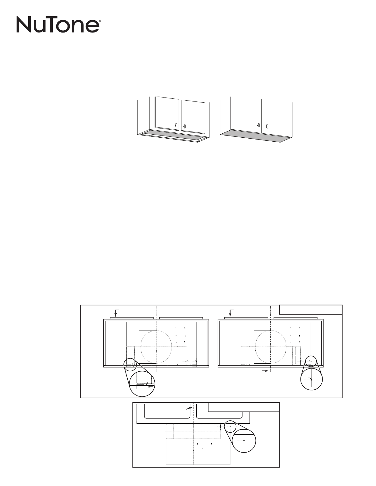
MANUEL D’INSTALLATION
INSTALLATION
14
Préparation de l’emplacement de la hotte
C
L
AB
Apoyar este borde contra la pared de atrásPlace this edge against back wall
VERTICAL EXHAUST
A
S
A
A
V
RTICAL EX
= 3¼” x 10”
= 3¼” x 14”
RECTANGULAR DUCTING7” ROUND DUCTING
OR
Use this template for marking; do not attempt to cut out the ducting hole through it.
NOTE: These cutouts are clearance holes; they do not need to be the exact size of ducting.
= 3¼ po x 10 po
= 3¼ po x 14 po
CONDUIT RECTANGULAIRECONDUIT ROND DE 7 PO
OU
= 3¼ pulg. x 10 pulg.
= 3¼ pulg. x 14 pulg.
CONDUCTO RECTANGULARCONDUCTO REDONDO
DE
7 PULG.
O
Appuyer ce bord au mur arrière
Utiliser ce gabarit pour marquer vos repères;ne pas tenter de découper
le trou pour le conduit à travers le gabarit.
NOTE : Les découpes incluent le jeu nécessaire à l’installation; elles ne doivent pas
être du format exact des conduits.
Use esta plantilla para crear marcados; no trate de cortar el
agujero del conducto a través de la plantilla.
NOTA: To be translated in Spanish.
MARK WHERE INDICATED
FOR THE APPROPRIATE SIZE DUCTOPENING
MARQUER LES REPÈRES AUX ENDROITS INDIQUÉSSELON
LE FORMAT DE CONDUIT UTILISÉ
TITLE TO BE TRANSLATED IN SPANISH
Electrical access hole center
A = single blower hood
B = double blower hood
Centre du trou pour fil
d’alimentation électrique
A = hotte ventilateur simple
B = hotte ventilateur double
To be translated in Spanish
Electrical access hole center
A = single blower hood
B = double blower hood
4¼”
10½”
14½”
8”
7½”
C
C
C
Bend template along graduated
scale when installing to framed
cabinet.
Pour une installation sous une
armoire à fond en retrait, utiliser les
lignes pour mesurer l’épaisseur du
décalage causé par le mur de
l’armoire et plier le gabarit en
conséquence.
To be translated in Spanish.
P
C
C
L
AB
VERTICAL EXHAUST
A
S
A
A
V
RTICAL EX
= 3¼” x 10”
= 3¼” x 14”
RECTANGULAR DUCTING7” ROUND DUCTING
OR
Use this template for marking; do not attempt to cut out the ducting hole through it.
NOTE: These cutouts are clearance holes; they do not need to be the exact size of ducting.
= 3¼ po x 10 po
= 3¼ po x 14 po
CONDUIT RECTANGULAIRECONDUIT ROND DE 7 PO
OU
= 3¼ pulg. x 10 pulg.
= 3¼ pulg. x 14 pulg.
CONDUCTO RECTANGULARCONDUCTO REDONDO
DE
7 PULG.
O
Utiliser ce gabarit pour marquer vos repères;ne pas tenter de découper
le trou pour le conduit à travers le gabarit.
NOTE : Les découpes incluent le jeu nécessaire à l’installation; elles ne doivent pas
être du format exact des conduits.
Use esta plantilla para crear marcados; no trate de cortar el
agujero del conducto a través de la plantilla.
NOTA: To be translated in Spanish.
MARK WHERE INDICATED
FOR THE APPROPRIATE SIZE DUCTOPENING
MARQUER LES REPÈRES AUX ENDROITS INDIQUÉSSELON
LE FORMAT DE CONDUIT UTILISÉ
TITLE TO BE TRANSLATED IN SPANISH
Electrical access hole center
A = single blower hood
B = double blower hood
Centre du trou pour fil
d’alimentation électrique
A = hotte ventilateur simple
B = hotte ventilateur double
To be translated in Spanish
Electrical access hole center
A = single blower hood
B = double blower hood
4¼”
10½”
14½”
8”
7½”
C
C
C
Bend template along graduated
scale when installing to framed
cabinet.
Pour une installation sous une
armoire à fond en retrait, utiliser les
lignes pour mesurer l’épaisseur du
décalage causé par le mur de
l’armoire et plier le gabarit en
conséquence.
To be translated in Spanish.
B
DEVANT
DE L’ARMOIRE
EMPLACEMENT DU
TROU POUR CÂBLE
D’ALIMENTATION
ÉLECTRIQUE (B)
(
DANS LE DESSOUS DE L’ARMOIRE)
LIGNE DE CENTRE
DEVANT
DE L’ARMOIRE
P
OUR UNE INSTALLATION SOUS UNE ARMOIRE À FOND
EN RETRAIT
, UTILISER LES LIGNES POUR MESURER
L
’ÉPAISSEUR DU DÉCALAGE CAUSÉ PAR LE MUR DE
L
’ARMOIRE ET PLIER LE GABARIT EN CONSÉQUENCE.
ÉVACUATION VERTICALE
C
L
AB
Place this edge against
cabinet bottom.
Appuyer ce bord contre le bas
de l’armoire.
Apoyar este borde contra
la base del armario.
HORIZONTAL EXHAUST
T
T
= 3¼ pulg. x 10 pulg.
= 3¼ pulg. x 14 pulg.
CONDUCTO RECTANGULAR
= 3¼” x 10”
= 3¼” x 14”
RECTANGULAR DUCTING
= 3¼ po x 10 po
= 3¼ po x 14 po
CONDUIT RECTANGULAIRE
MARK WHERE INDICATED
FOR THE APPROPRIATE SIZE DUCT OPENING
MARQUER LES REPÈRES AUX ENDROITS INDIQUÉS SELON
LE FORMAT DE CONDUIT UTILISÉ
TITLE TO BE TRANSLATED IN SPANISH
Use this template for marking;do not attempt to cut out the ducting hole through it.
NOTE: These cutouts are clearance holes; they do not need to be the exact size of ducting.
Utiliser ce gabarit pour marquer vos repères;ne pas tenter de découper
le trou pour le conduit à travers le gabarit.
NOTE : Les découpes incluent le jeu nécessaire à l’installation; elles ne doivent pas
être du format exact des conduit
s.
Use esta plantilla para crear marcados;no trate de cortar el
agujero del conducto a través de la plantilla.
NOTA: To be translated in Spanish.
Electrical access hole center
A = single blower hood
B = double blower hood
Centre du trou pour fil
d’alimentation électrique
A = hotte ventilateur simple
B = hotte ventilateur double
To be translated in Spanish
Electrical access hole center
A = single blower hood
B = double blower hood
B
ess hole center
wer hood
wer hood
LIGNE DE CENTRE
EMPLACEMENT DU TROU POUR CÂBLE
D’ALIMENTATION ÉLECTRIQUE (B)
(
DANS LE MUR)
ÉVACUATION HORIZONTALE
NOTE : Avant de commencer l’installation, veuillez lire toutes les étapes de cette instruction.
Identifier votre type d’armoire de cuisine à l’aide de l’illustration ci-dessous.
Système d’installation par une personne EZ1
L’installation EZ1 a été conçue pour être utilisée avec des armoires de cuisine ayant la même
largeur que la hotte de cuisinière. Si la largeur de l’armoire dépasse de 1/2 po la largeur de la
hotte, veuillez utiliser la méthode d’installation standard.
1 ] Utiliser le gabarit approprié (inclus) pour évacuation verticale OU horizontale pour déterminer
l’emplacement des conduits et du câble d’alimentation dans l’armoire ou dans le mur. Pour
une installation sans conduit, NE PAS pratiquer d’ouverture; découper seulement un trou pour
le câble d’alimentation. Lors d’un remplacement d’une hotte, si vous prévoyez utiliser les
conduits et le câble électrique déjà existants, les étapes 2 à 5 pourraient ne pas être
nécessaires. Le cas échéant, aller directement à l’étape 6.
2 ] Mesurer et tracer la ligne de centre de l’armoire sous l’armoire (ou sur le mur arrière).
3 ] Aligner la ligne de centre du gabarit avec celle tracée sous l’armoire (ou le mur arrière), en appuyant
le bord du gabarit (où il est indiqué) contre le mur arrière. Pour une installation à évacuation verticale
sous une armoire à fond en retrait, plier le bord du gabarit de la valeur de l’épaisseur du bord de
l’armoire appuyé au mur (utiliser les lignes C du gabarit). Fixer le gabarit en place avec du ruban adhésif.
NOTE : Face à l’installation, les lettres A et B (sur le gabarit) sont à droite.
Ce manuel couvre deux types d’installation : l’installation standard (sans les supports EZ1) et le
système d’installation par une personne EZ1 (en utilisant le gabarit et les supports inclus). Pour
l’installation standard, allez en page 19.
ARMOIRE À FOND EN RETRAIT ARMOIRE À FOND ÉGAL
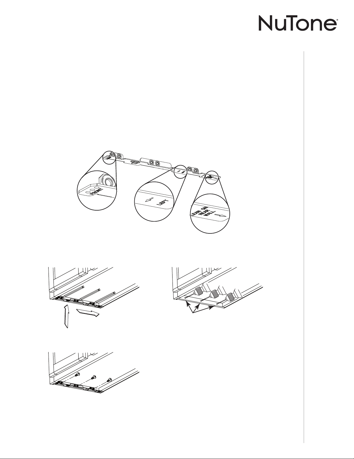
MANUEL D’INSTALLATION
INSTALLATION
15
ARMOIRE À
FOND EN RETRAIT
7/64 po
Voir les inscriptions sur les supports pour les installer dans le bon sens (inscriptions en anglais
seulement : front = avant, left = gauche, lean on rear wall = appuyer sur le mur arrière).
Appuyer le support correspondant au rebord latéral de l’armoire, tout en appuyant
l’extrémité arrière du support contre le mur. Utiliser un crayon pour tracer l’emplacement
de 3 trous (il y a 6 trous mais seulement 3 sont nécessaires).
Retirer le support. À l’aide d’un foret de 7/64 po, percer les 3 trous où ils sont indiqués.
Fixer le support au rebord latéral de l’armoire à l’aide d’un tournevis Phillips et de
3 vis à bois n° 8 x 5/8 po. Répéter l’opération pour l’autre côté de l’armoire.
7 ] Installer les supports d’installation appropriés selon le type d’armoire (à fond en retrait ou
fond égal). Voir ci-dessous.
4 ] Percer un avant-trou de 1/8 po de diamètre pour le câble d’alimentation, à l’emplacement B
sur le gabarit.
5 ] Utiliser un crayon pointu ou un foret de 1/8 po pour marquer les repères du trou pour
le conduit approprié (16 endroits pour le conduit rond de 7 po, ou aux 4 coins pour les
conduits rectangulaires). Retirer le gabarit.
6 ] Dessiner le contour du trou pour le conduit d’évacuation en reliant les repères (16 pour le
conduit rond de 7 po ou 4 pour le conduit rectangulaire), pour découper l’ouverture dans le
dessous de l’armoire (évacuation verticale) ou dans le mur (évacuation horizontale). Percer
le trou pour le câble d’alimentation électrique à l’aide d’une scie cloche de 1½ po centrée
avec l’avant-trou percé précédemment à l’étape 4.

MANUEL D’INSTALLATION
INSTALLATION
16
[ \
7/64”
X
3 X
Y
Z
Voir les inscriptions sur les supports pour les installer dans le bon sens (inscriptions en anglais
seulement : front = avant, left = gauche, lean on rear wall = appuyer sur le mur arrière).
Aligner le support correspondant au côté de l’armoire, tout en appuyant l’extrémité arrière
du support contre le mur. Tracer une ligne le long du rebord externe du support (tel qu’il
est illustré).
Glisser le support vers le centre de l’armoire et aligner ses côtés extérieurs sur la ligne
tracée, en gardant l’extrémité arrière toujours appuyée au mur.
À l’aide d’un crayon, tracer les 3 trous.
Retirer le support. À l’aide d’un foret de 7/64 po, percer les 3 trous où ils sont indiqués.
Fixer le support au bas de l’armoire à l’aide d’un tournevis Phillips et de 3 vis à bois à tête
fraisée fournies. Répéter l’opération pour l’autre côté de l’armoire.
ARMOIRE
À FOND ÉGAL
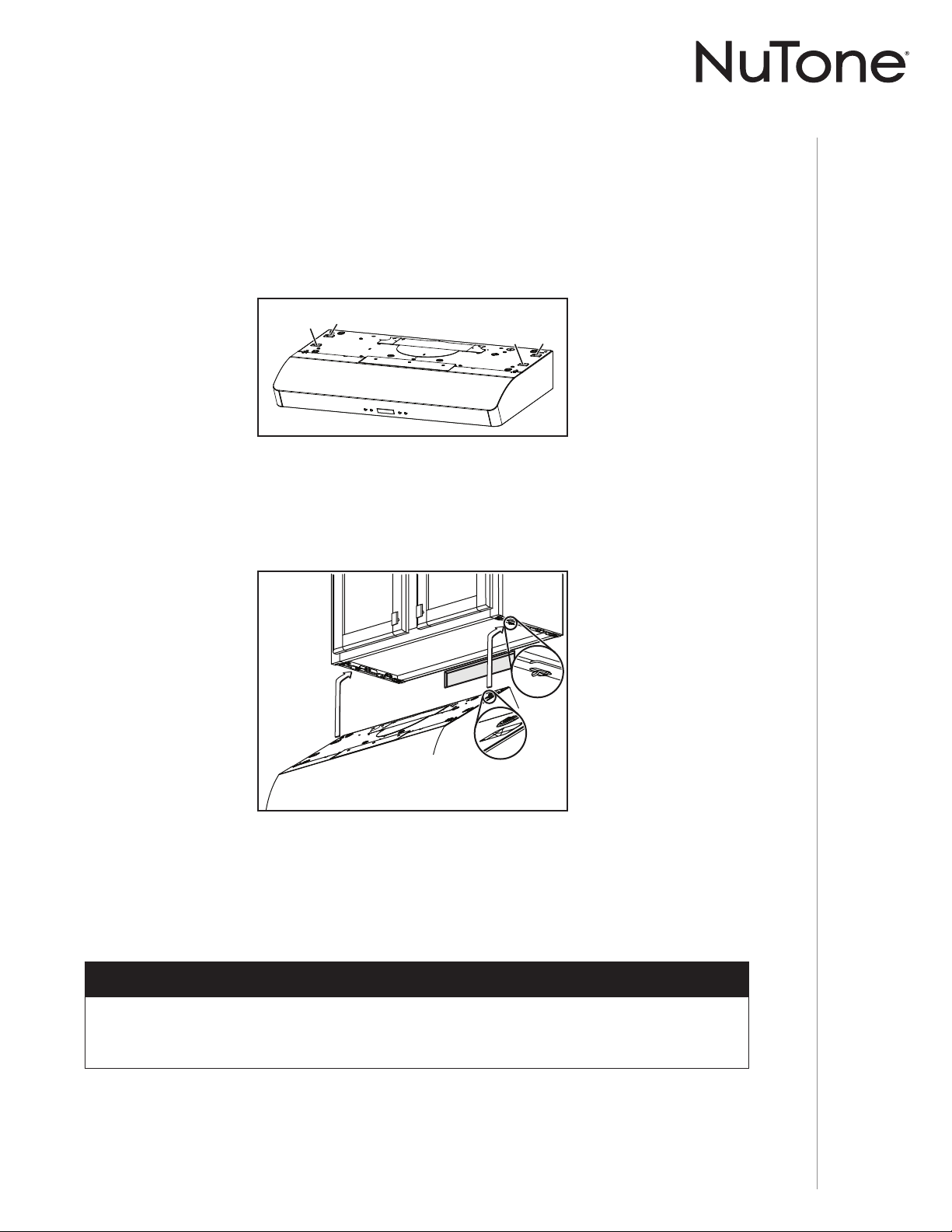
MANUEL D’INSTALLATION
INSTALLATION
17
A
C
B
D
Installation de la hotte (avec supports EZ1)
1 ] Acheminer le câble d’alimentation depuis le panneau de distribution de la maison jusqu’à
l’emplacement de la hotte.
2 ] De chaque côté de la hotte, sur le dessus, se trouvent 2 paires de trous enfoncés (à l’arrière :
A et B, à l’avant : C et D dans l’illustration ci-dessous); ces trous permettent à la hotte de
s’accrocher aux supports (installés précédemment).
3 ] Accrocher temporairement la hotte aux supports, uniquement par les (2) TROUS ENFONCÉS
ARRIÈRE (A et B). Tout en retenant la hotte, passer le câble d’alimentation électrique dans
la hotte à travers le serre-fils installé précédemment à l’étape 6 en page 11.
4 ] Décrocher les trous arrière de la hotte des supports et accrocher la hotte en utilisant ses
(2) TROUS ENFONCÉS AVANT (C et D). Tout en retenant la hotte, aller à l’étape 6.
5 ] Accrocher la hotte aux supports par les (2) TROUS ENFONCÉS AVANT (C et D). Tout en
retenant la hotte, insérer le câble d’alimentation dans un serre-fils approprié de 1/2 po
de diamètre (non inclus), serrer le serre-fils, puis l’insérer dans l’ouverture pour le câble
d’alimentation.
NOTE : Voir la page suivante pour les dernières étapes de cette instruction.
INSTALLATION POUR ÉVACUATION HORIZONTALE SEULEMENT
INSTALLATION POUR ÉVACUATION VERTICALE ET SANS CONDUITS SEULEMENT
OTE : N La procédure convient autant pour les armoires à fond en retrait qu’à fond égal.
INSTALLATION AVEC CONDUITS SEULEMENT
6 ] Raccorder le conduit à la hotte et sceller les joints avec du ruban adhésif de métal.
S’assurer que l’adaptateur/volet (ou la plaque pour conduit rond) entre dans le conduit et
que son volet ouvre et ferme librement.
A
B
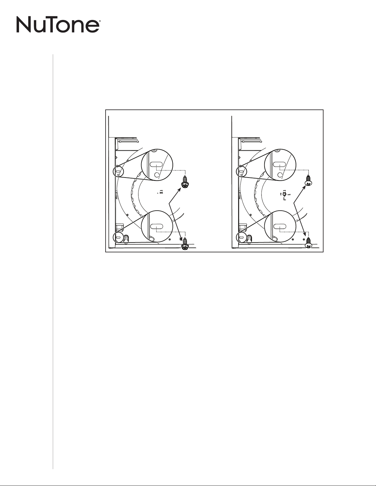
MANUEL D’INSTALLATION
INSTALLATION
18
ARMOIRE À
FOND EN RETRAIT
ARMOIRE AVEC
FOND ÉGAL
7 ] Pour une armoire à fond en retrait, fixer la hotte au supports EZ1 à l’aide de quatre (4) vis à
métaux n° 8-18 x 1/2 po (incluses dans le sac de pièces). Insérer deux (2) vis par côté, dans
les fentes (tel qu’il est démontré dans les médaillons de l’illustration ci-dessous).
8 ] Pour une armoire à fond égal, fixer la hotte à l’armoire à l’aide de quatre (4) vis à bois à tête
ronde n° 8 x 5/8 po (incluses dans le sac de pièces). Insérer deux (2) vis par côté, dans les
fentes (tel qu’il est démontré dans les médaillons de l’illustration ci-dessous).
9 ] Fixer le câble d’alimentation électrique à la hotte à l’aide du serre-fils.
VIS À BOIS
VIS À
MÉTAUX
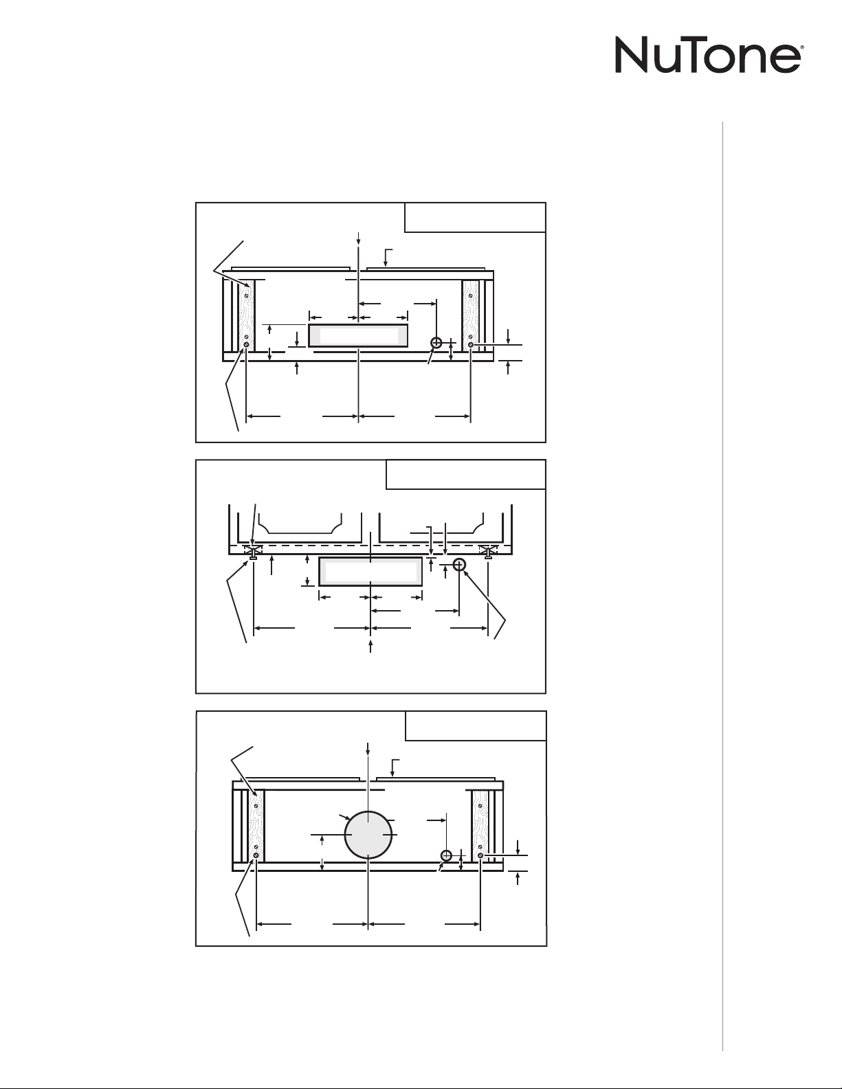
MANUEL D’INSTALLATION
INSTALLATION
19
Installation standard (sans supports EZ1)
1 ] Utiliser le diagramme approprié ci-dessous pour déterminer l’emplacement exact des coupes
à effectuer pour le conduit et le fil d’alimentation électrique dans l’armoire ou le mur. Pour une
installation en recirculation, NE PAS découper un trou pour le conduit.
2 ] Visser à mi-hauteur deux (2) vis de montage n° 8 x 5/8 po, À TÊTE RONDE, dans les cales/
armoire, selon le diagramme approprié ci-dessus. Les 2 autres vis de montage n° 8 x 5/8 po
À TÊTE RONDE seront installées plus tard. (Les vis de montage sont incluses dans le sac de
pièces, mais les cales de bois et leurs vis ne le sont pas.)
5¼ PO
5¼ PO
LIGNE
DE CENTRE
3/4 PO
1½ PO
9¾ PO
12⅞ PO
4
7
/16 PO
12⅞ PO
DESSOUS DE
L’ARMOIRE
DEVANT
DE L’ARMOIRE
TROU POUR
CONDUIT VERTICAL
VIS DE MONTAGE ARRIÈRE DE LA HOTTE (2)
TROU POUR FIL
D’ALIMENTATION
ÉLECTRIQUE (
DANS LE
DESSOUS
DE L’ARMOIRE)
1⅜
PO
CALES DE BOIS
(
SEULEMENT POUR
ARMOIRES
À BASE EN RETRAIT)
ÉVACUATION VERTICALE
3¼ PO X 10 PO
3⅞ PO
13/16 PO
3/16 PO
5¼ PO
5¼ PO
12⅞ PO
12⅞ PO
9¾ PO
CALES DE BOIS
(
SEULEMENT POUR ARMOIRES
À
BASE EN RETRAIT)
DEVANT DE L’ARMOIRE
TROU POUR
CONDUIT HORIZONTAL
DESSOUS
DE
L’ARMOIRE
VIS DE MONTAGE
ARRIÈRE DE
LA HOTTE (2)
LIGNE
DE CENTRE
TROU POUR FIL
D’ALIMENTATION
ÉLECTRIQUE
(
DANS LE MUR)
ÉVACUATION HORIZONTALE
3¼ PO X 10 PO
4¹¹/16 PO
1½ PO
1⅜ PO
9¾ PO
12⅞ PO 12⅞ PO
DEVANT
DE L’ARMOIRE
LIGNE
DE CENTRE
CALES DE BOIS
(SEULEMENT POUR ARMOIRES
À
BASE EN RETRAIT)
DESSOUS DE
L’ARMOIRE
TROU POUR FIL
D’ALIMENTATION
ÉLECTRIQUE (
DANS LE
DESSOUS
DE L’ARMOIRE)
ROU POUR
ROU POUR
CONDUIT
CONDUIT
ROND DE
ROND DE
7
7
PO
PO
TROU POUR
CONDUIT
ROND DE
7
PO
TROU DE
8
PO DIA.
VIS DE MONTAGE ARRIÈRE DE LA HOTTE (2)
ÉVACUATION VERTICALE
7 PO ROND
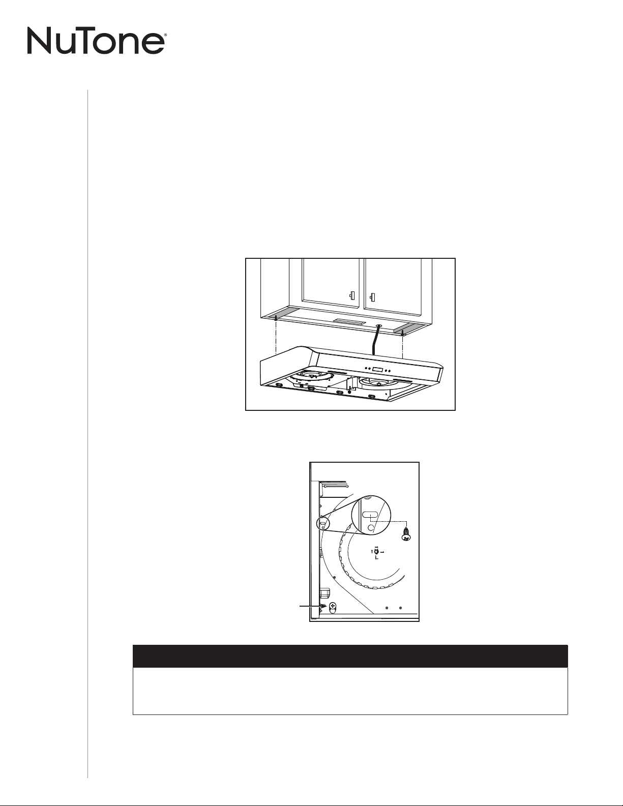
MANUEL D’INSTALLATION
INSTALLATION
20
Installation de la hotte (installation standard)
1 ] Acheminer le câble d’alimentation électrique du panneau de distribution jusqu’à l’emplacement
de la hotte. Si l’ouverture pour le câble d’alimentation est à l’arrière de la hotte, insérer le
câble d’alimentation dans la hotte à travers le serre-fils installé précédemment à l’étape 6 en
page 11. Si l’ouverture pour le câble d’alimentation est sur le dessus de la hotte, insérer le
câble d’alimentation dans un serre-fils approprié de 1/2 po de diamètre (non inclus), serrer le
serre-fils, puis l’insérer dans l’ouverture pour le câble d’alimentation.
2 ] Suspendre la hotte à l’aide des (2) vis de montage arrière installées précédemment. Glissez
la hotte vers le mur de manière à engager la tête des vis dans la partie étroite des trous en
forme de serrure du dessus de la hotte. Serrer les vis fermement et maintenir la hotte jusqu’à
ce que l’étape 3 soit terminée.
3 ] Fixer la hotte à l’armoire à l’aide des deux vis de montage n° 8 x 5/8 po à tête ronde
(incluses dans le sac de pièces). Insérer une vis par côté, dans les fentes (tel qu’il est
illustré ci-dessous). Fixer le fil d’alimentation à la hotte à l’aide du serre-fils.
4 ] Raccorder le conduit à la hotte et sceller les joints avec du ruban adhésif de métal. S’assurer
que l’adaptateur/volet (ou la plaque pour conduit rond, sans volet) entre dans le conduit et que
son volet ouvre et ferme librement.
INSTALLATION AVEC CONDUITS SEULEMENT
OTE : N Deux installateurs sont recommandés lors de l’installation en raison du poids de cette hotte.
ARRIÈRE DE LA HOTTE
Vis serrée précédemment
à l’étape 2.
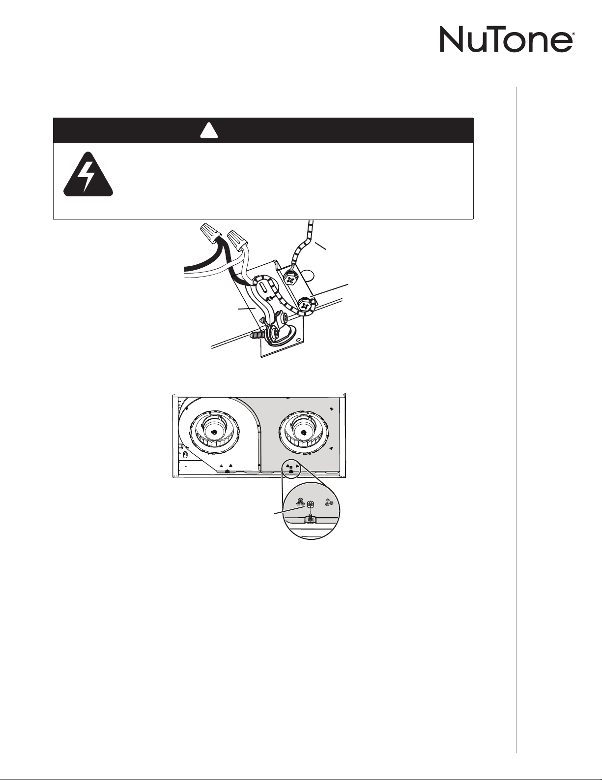
MANUEL D’INSTALLATION
INSTALLATION
21
Branchement électrique
!
AVERTISSEMENT
Risque d’électrocution. Le raccordement électrique doit être effectué
par du personnel qualifi é conformément aux codes et aux standards
en vigueur. Avant d’effectuer le branchement, coupez l’alimentation
électrique au panneau de distribution et verrouillez-le pour éviter une
mise en marche accidentelle.
FIL DE MISE
À LA TERRE
DES MOTEURS
CÂBLE ÉLECTRIQUE
DE LA MAISON
VIS DE MISE
À LA TERRE
1 ] Connecter le câble électrique de la maison avec les fils de la hotte : le fil NOIR au fil NOIR, le
fil BLANC au BLANC et le fil VERT ou fil dénudé à la vis VERTE de mise à la terre.
2 ] Remettre en place le couvercle du ventilateur (en gris dans l’illustration ci-dessus) à l’aide
des 7 vis et de l’écrou retirés précédemment à l’étape 4 en page 10. Porter attention à
l’emplacement de la vis 1, à partir de l’arrière de la hotte, elle doit être installée à gauche de
l’écrou (voir le médaillon).
1
2
3
45
6
7
ARRIÈRE DE
LA HOTTE
Installation des filtres
Installation avec conduits seulement :
Remettre en place les filtres à graisses retirés à l’étape 3 en page 10 dans la section « Préparation
de la hotte ».
Installation en recirculation seulement :
Se procurer deux filtres de recirculation chez votre distributeur ou votre détaillant local (consulter
l’étiquette de spécification pour connaître le type de filtre). Installer les filtres de recirculation selon
les directives incluses avec ceux-ci.
1
ÉCROU
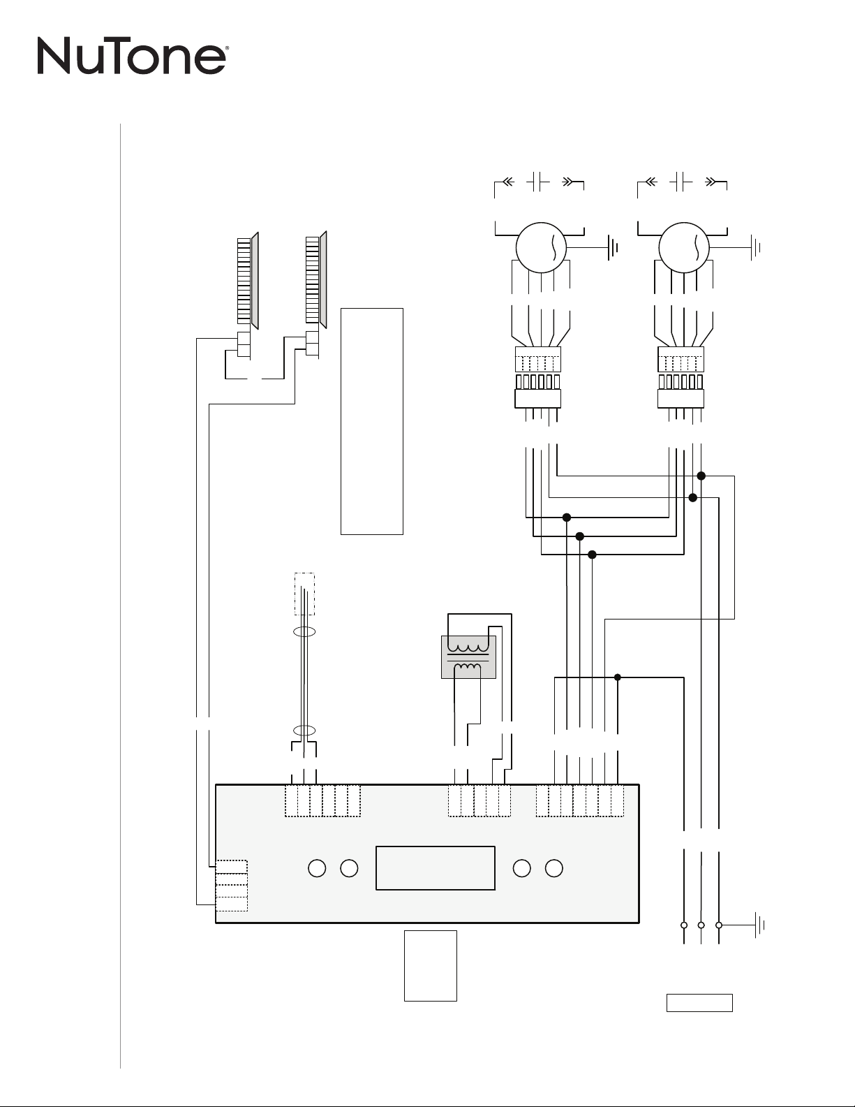
MANUEL D’INSTALLATION
SCHÉMA ÉLECTRIQUE
22
N
V/J
N
24 V
Class 2
BLA
R
BLE
BLE
R
R
N (H)
N
R (B)
O (M)
N (H)
V/J
J2
54
1 6
J4
J1
1
2
3
4
5
3
4
5
6
7
1
2
3
2
1
4
INTERFACE ACL
Alimentation,
Moteur
Transformateur
DEL
O (M)
O (M)
N (H)
R (B)
R (B)
V/J
Plaque électronique
Commande
prioritaire
ADA
BLA
BLA
BLA
BLA
Transformateur
BLA
R
N
Ref: 990729478A
DEL
2 1
DEL
2 1
BLA
R
N
O
V/J
1
2
3
5
4
6
BLA
R
N
O
V/J
1
2
3
5
4
6
N
Ligne
Neutre
Mise à
la terre
120 V CA
M
M
BR
BR/BLA
C
BR/BLA
C
BR
N
N
N
N
23
J6
CODE DES COULEURS
BLA
BLE
BR
BR/BLA
BLANC
BLEU
BRUN
BRUN/BLANC
N
O
R
V/J
NOIR
ORANGE
ROUGE
VERT/JAUNE
Gaine thermorétractable
MOTEUR DU
VENTILATEUR
MOTEUR DU
VENTILATEUR
Note : La carte
électronique est
illustrée avec les
connecteurs au
côté opposé.
SÉRIE AVDN1 (DEUXIÈME GÉNÉRATION)
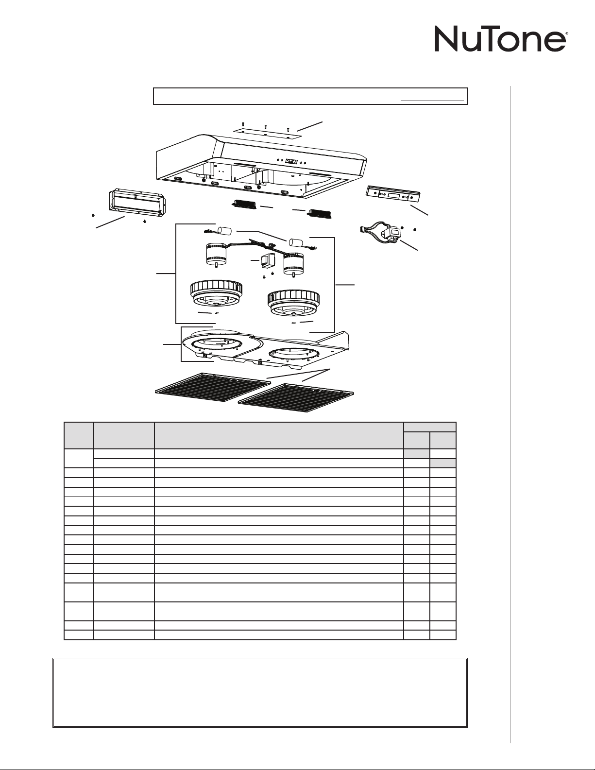
MANUEL D’INSTALLATION
PIÈCES DE RECHANGE
23
SÉRIE AVDN1
Première génération : Numéro de série 091810008492 et précédents.
B
C
D
E
H
I
K
L
M
F
F
J
REPÈRE Nº DE PIÈCE DESCRIPTION
QUANTITÉ
30 PO
INOX.
30 PO
BLANC
1
S97020030 P
LAQUE DE GRILLE DE RECIRCULATION, BLANCHE (INCLUANT LES VIS)1
S97020031 PLAQUE DE GRILLE DE RECIRCULATION, INOX. (INCLUANT LES VIS)1
2 S97020534 ADAPTATEUR/VOLET DE 3¼ PO X 10 PO (INCLUANT LES VIS)11
3 S97020412 C
ONDENSATEUR (INCLUANT LES ATTACHES AUTOBLOQUANTES)22
4 S97020842 ENSEMBLE MOTEUR ROTATION À DROITE (INCLUANT LES REPÈRES 3 ET 5 ET VISSERIE)1 1
5 SR99420635 C
LIP DE ROUE 22
6 S97021337 C
OUVERCLES DES VENTILATEURS (AVEC ANNEAUX D’ADMISSION)11
7 S97020204-002 FILTRE À GRAISSES - HYBRIDE -TYPE C5 (ENSEMBLE DE 2) 1 1
8 S97020843 ENSEMBLE MOTEUR ROTATION À GAUCHE (INCLUANT LES REPÈRES 3 ET 5 ET VISSERIE)1 1
9 S97020797 A
UTOTRANSFORMATEUR (AVEC VIS)11
10 S97020444 M
ODULES DEL (PAIRE)11
11 S97021392 E
NSEMBLE TRANSFORMATEUR, 24 V 18 VA (AVEC VIS)11
12 S97020459 COMMANDE À CRISTAUX LIQUIDES (AVEC VIS)11
* S97020796 FAISCEAU DE FILS AVEC AUTOTRANSFORMATEUR ET FUSIBLE 11
* S97020360
S
AC DE PIÈCES COMPRENANT : 4 VIS À MÉTAUX N° 8-18 X 1/2 PO,
6
VIS À BOIS À TÊTE RONDE N° 8 X 5/8 PO, 6 VIS À TÊTE FRAISÉE N° 8 X 1/2 PO
11
* S97020466
FILTRES DE RECIRCULATION - TYPE XC (ENSEMBLE DE 2)
(
INSTALLATION SANS CONDUIT SEULEMENT)
11
* S99527587 C
LIPS POUR FILTRE AU CHARBON (ENSEMBLE DE 4) 1 1
* S97020470 ENSEMBLE D’INSTALLATION EASY INSTALL (INCLUANT LA VISSERIE)11
* ARTICLE NON ILLUSTRÉ.
PIÈCE DE REMPLACEMENT ET SERVICE
Pour assurer le bon fonctionnement de votre appareil, vous devez toujours utiliser des pièces d’origine provenant de Venmar
Ventilation ULC. Les pièces d’origine de Venmar Ventilation ULC sont spécialement conçues pour satisfaire toutes les normes de
certification de sécurité applicables. Leur remplacement par des pièces ne provenant pas de Venmar Ventilation ULC pourrait ne
pas assurer la sécurité de l’appareil, entraîner une réduction sévère des performances ainsi qu’un risque de défaillance prématurée.
Venmar Ventilation ULC recommande également de toujours vous référer à une entreprise de services compétente et reconnue par
Venmar Ventilation ULC pour vos pièces de remplacement et appels de service.
G
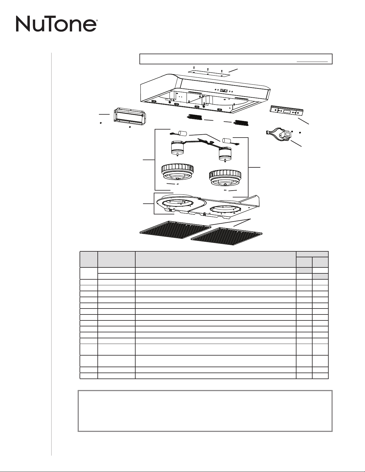
MANUEL D’INSTALLATION
PIÈCES DE RECHANGE
24
* ARTICLE NON ILLUSTRÉ.
PIÈCE DE REMPLACEMENT ET SERVICE
Pour assurer le bon fonctionnement de votre appareil, vous devez toujours utiliser des pièces d’origine provenant de Venmar
Ventilation ULC. Les pièces d’origine de Venmar Ventilation ULC sont spécialement conçues pour satisfaire toutes les normes de
certification de sécurité applicables. Leur remplacement par des pièces ne provenant pas de Venmar Ventilation ULC pourrait ne
pas assurer la sécurité de l’appareil, entraîner une réduction sévère des performances ainsi qu’un risque de défaillance prématurée.
Venmar Ventilation ULC recommande également de toujours vous référer à une entreprise de services compétente et reconnue par
Venmar Ventilation ULC pour vos pièces de remplacement et appels de service.
SÉRIE AVDN1
C
D
E
H
I
J
K
L
F
F
B
G
Deuxième génération : Numéro de série 091810008493 et suivants.
REPÈRE Nº DE PIÈCE DESCRIPTION
QUANTITÉ
30 PO
INOX.
30 PO
BLANC
1
S97020030 P
LAQUE DE GRILLE DE RECIRCULATION, BLANCHE (INCLUANT LES VIS)1
S97020031 PLAQUE DE GRILLE DE RECIRCULATION, INOX. (INCLUANT LES VIS)1
2 S97020534 ADAPTATEUR/VOLET DE 3¼ PO X 10 PO (INCLUANT LES VIS)11
3 S97020412 CONDENSATEUR (INCLUANT LES ATTACHES AUTOBLOQUANTES)22
4 S97021326 E
NSEMBLE VENTILATEUR ROTATION À DROITE (INCLUANT LES REPÈRES 3 ET 5 ET VISSERIE)1 1
5 SR99420635 CLIP DE ROUE 22
6 S97021339 COUVERCLES DES VENTILATEURS (AVEC ANNEAUX D’ADMISSION)11
7 S97020204-002 FILTRE À GRAISSES - HYBRIDE -TYPE C5 (ENSEMBLE DE 2) 1 1
8 S97021327 E
NSEMBLE VENTILATEUR ROTATION À GAUCHE (INCLUANT LES REPÈRES 3 ET 5 ET VISSERIE)1 1
9 S97020444 M
ODULES DEL (PAIRE)11
10 S97021392 E
NSEMBLE TRANSFORMATEUR, 24 V 18 VA (AVEC VIS)11
11 S97020459 COMMANDE À CRISTAUX LIQUIDES 11
* S97020454 FAISCEAU DE FILS 11
* S97020360
SAC DE PIÈCES COMPRENANT : 4 VIS À MÉTAUX N° 8-18 X 1/2 PO,
6 VIS À BOIS À TÊTE RONDE N° 8 X 5/8 PO, 6 VIS À TÊTE FRAISÉE N° 8 X 1/2 PO
11
* S97020466
FILTRES DE RECIRCULATION - TYPE XC (ENSEMBLE DE 2)
(INSTALLATION SANS CONDUIT SEULEMENT)
11
* S99527587 CLIPS POUR FILTRE AU CHARBON (ENSEMBLE DE 4) 1 1
* S97020470 E
NSEMBLE D’INSTALLATION EASY INSTALL (INCLUANT LA VISSERIE)11

MANUEL D’INSTALLATION
GARANTIE
25
Garantie limitée
Période de garantie et exclusions : Venmar Ventilation ULC (la « Société ») garantit au consommateur acheteur initial (« vous »)
de son produit (le « Produit ») que celui-ci est exempt de tout vice de matériau ou de fabrication pour une période de un (1) an à
compter de la date d’achat originale (ou toute période plus longue que pourrait exiger une loi applicable). Pour les hottes munies de
modules à DEL intégrés, la Société garantit que les modules à DEL ainsi que le module d’alimentation DEL sont exempts de tout
vice de matériau pour une période de trois (3) ans. La période de la garantie limitée sur toute pièce de remplacement fournie par
la Société et sur tout produit réparé ou remplacé en vertu de la présente garantie limitée correspond au reste de la période de
garantie originale (ou toute période plus longue que pourrait exiger une loi applicable).
La présente garantie ne s’applique pas aux tubes uorescents et aux démarreurs, ni aux ampoules halogènes ou incandescentes,
fusibles, ltres, conduits, capuchons de toit, capuchons muraux et autres accessoires pour conduits pouvant avoir été achetés
séparément et installés avec le produit. La présente garantie ne couvre pas (a) les travaux d’entretien et de service normaux,
(b) l’usure normale, (c) tout produit ou toute pièce ayant fait l’objet d’une mauvaise utilisation, d’un abus, d’un usage anormal,
d’une négligence, d’un accident, d’un entretien, rangement ou réparation inadéquats ou insuf sants (autre que par la Société),
(d) les dommages dus à une mauvaise installation, ou à une installation ou utilisation contraires aux recommandations ou
instructions, (e) tout produit déplacé de son lieu d’installation original, (f) les dommages dus à des éléments environnementaux
ou naturels, (g) les dommages dus au transport, (h) l’usure naturelle du ni, (i) les produits utilisés à des ns commerciales ou
non-résidentielles ou (j) les dommages dus à un incendie, à une inondation ou à un événement fortuit, (k) les produits dont les
numéros de série ont été altérés, rendus illisibles ou enlevés. La présente garantie ne couvre que les produits vendus au consommateur
initial au Canada par la Société ou par les distributeurs canadiens autorisés par la Société.
La présente garantie remplace toute garantie précédente et le consommateur et acheteur initial ne peut la céder à quiconque.
Aucune autre garantie : La présente garantie limitée stipule les seules obligations de la Société et votre seul recours en cas
de produits défectueux. La garantie ci-dessus est exclusive et remplace toute autre garantie, expresse ou tacite. LA SOCIÉTÉ
EXCLUT TOUTE AUTRE GARANTIE OU CONDITION EXPRESSE ET TOUTE GARANTIE OU CONDITION DÉCOULANT
IMPLICITEMENT DE LA LOI, Y COMPRIS, SANS S’Y LIMITER, LES GARANTIES DE VALEUR MARCHANDE ET
D’ADÉQUATION À UN USAGE PARTICULIER. Dans la mesure où la loi en vigueur interdit l’exclusion des garanties tacites ou
conditions, la durée de toute garantie tacite est limitée à la période stipulée ci-dessus pour la garantie expresse. Certains territoires
ou provinces interdisant de limiter la durée d’une garantie tacite, la limitation ci-dessus peut ne pas s’appliquer à votre situation.
Toute description verbale ou écrite du produit a pour seule n de l’identi er et ne doit pas être interprétée comme une garantie expresse.
Si possible, chaque disposition de cette garantie limitée doit être interprétée de sorte à être en vigueur et valide en vertu des
lois applicables, mais si une disposition s’avère interdite ou invalide, elle le sera seulement dans la mesure de cette interdiction
ou invalidité, sans invalider le reste de cette disposition ni les autres dispositions de la présente garantie limitée.
Recours : Pendant la période de garantie limitée applicable, la Société pourra, à son choix, fournir des pièces de rechange
ou réparer ou remplacer, sans frais, tout produit ou toute pièce, dans la mesure où la Société constate qu’il est couvert et
contrevient à la présente garantie limitée dans des conditions normales d’utilisation et de service. La Société vous enverra
gratuitement le produit réparé ou remplacé ou les pièces de rechange. Vous êtes responsable des frais de démontage, de
remontage, d’expédition, d’assurance ou de tous autres frais de transport pour l’envoi du produit ou de la pièce à la Société. Si
vous devez envoyer le produit ou la pièce à la Société, tel que la Société vous l’indiquera, vous devrez l’emballer correctement.
La Société n’est pas responsable des dommages subis lors du transport. La Société se réserve le droit d’utiliser des produits ou
des pièces remis en état, remis à neuf, réparés ou réusinés dans le processus de réparation ou de remplacement sous garantie.
Lesdits produits ou pièces seront comparables en fonction et en performance aux produits et pièces d’origine et seront garantis
pendant le reste de la période de garantie originale (ou toute période plus longue que pourrait exiger une loi applicable).
La Société se réserve le droit, à son entière discrétion, de vous rembourser le prix que vous avez payé pour votre produit en lieu
et place d’une réparation ou d’un remplacement. Si le produit ou le composant n’est plus offert, il sera remplacé par un produit de
valeur égale ou supérieure, à l’entière discrétion de la Société. Cette mesure constitue votre recours exclusif en cas de violation
de cette garantie limitée.
Exclusion de dommages : L’OBLIGATION DE LA SOCIÉTÉ DE FOURNIR DES PIÈCES DE RECHANGE, OU DE RÉPARER
OU REMPLACER LE PRODUIT, À SON CHOIX, CONSTITUE VOTRE SEUL ET UNIQUE RECOURS EN VERTU DE LA
PRÉSENTE GARANTIE LIMITÉE ET LA SEULE ET UNIQUE OBLIGATION DE LA SOCIÉTÉ. LA SOCIÉTÉ NE PEUT ÊTRE
TENUE RESPONSABLE DE TOUT DOMMAGE INDIRECT, CONSÉCUTIF, ACCESSOIRE OU SPÉCIAL DÉCOULANT DE
L’UTILISATION OU DU RENDEMENT DU PRODUIT. Les dommages accessoires comprennent, sans pour autant y être limités,
la perte de temps et la privation de jouissance. Les dommages indirects comprennent, sans pour autant y être limités, le coût de
réparation ou de remplacement des autres biens endommagés par le mauvais fonctionnement du produit.
LA SOCIÉTÉ NE POURRA ÊTRE TENUE RESPONSABLE EN RIEN, NI À TOUTES PERSONNES, DE TOUTE OBLIGATION OU
RESPONSABILITÉ INCLUANT SANS S’Y LIMITER, LES OBLIGATIONS OU RESPONSABILITÉS ÉMANANT D’UN BRIS DE
CONTRAT OU D’UNE VIOLATION DE GARANTIE, LA NÉGLIGENCE OU AUTRE FORME DE PRÉJUDICE, OU TOUT AUTRE THÉORIE
DE STRICTE RESPONSABILITÉ CONCERNANT LE PRODUIT, LES ACTIONS, OMISSIONS OU AUTRE DE LA SOCIÉTÉ.
Certains territoires ou provinces ne permettant pas la limitation ou l’exclusion des dommages indirects ou consécutifs, la limitation
ci-dessus peut ne pas s’appliquer à votre situation. La présente garantie vous confère des droits spéci ques reconnus par la loi.
D’autres droits pourraient également vous être accordés selon la législation locale en vigueur.
La présente garantie ne couvre que le remplacement ou la réparation des produits ou pièces défectueux à l’usine principale de la
Société et ne comprend pas les frais de voyage et ni les dépenses quotidiennes pour une réparation à domicile.
Toute aide que la Société vous fournit en dehors des dispositions, limitations ou exclusions de cette garantie limitée ne constituera
en rien une renonciation auxdites dispositions, limitations ou exclusions, et ne prolongera aucunement cette garantie pas plus
qu’elle ne la remettra en vigueur. Les conditions, exclusions et les limitations de responsabilités au titre de la présente garantie ne
s’appliqueront pas dans la mesure où toute loi applicable l’interdit.
La Société ne vous remboursera aucune dépense encourue par vous pour la réparation ou le remplacement de tout produit
défectueux, sauf celles que vous avez encourues avec la permission écrite préalable de la Société.
Comment bénéfi cier du service de garantie : Pour vous prévaloir de cette garantie, vous devez (a) aviser la Société à l’adresse
ou au numéro de téléphone indiqués ci-dessous dans les sept (7) jours du constat de la défectuosité couverte, (b) donner le
numéro de modèle du produit et le numéro d’identi cation de la pièce et (c) décrire la nature de la défectuosité du produit ou de
la pièce. Lors de votre demande de garantie, vous devez présenter une preuve de la date d’achat originale. Si vous ne pouvez pas
fournir une copie écrite de la garantie limitée originale, les dispositions de la garantie limitée écrite la plus récente de la Société
concernant ce produit particulier s’appliqueront. Vous trouverez les garanties limitées écrites les plus récentes des produits de la
Société sur le site www.nutone.ca.
Venmar Ventilation ULC, 550 boul. Lemire, Drummondville, Québec, Canada J2C 7W9 www.nutone.ca 1 877 896-1119