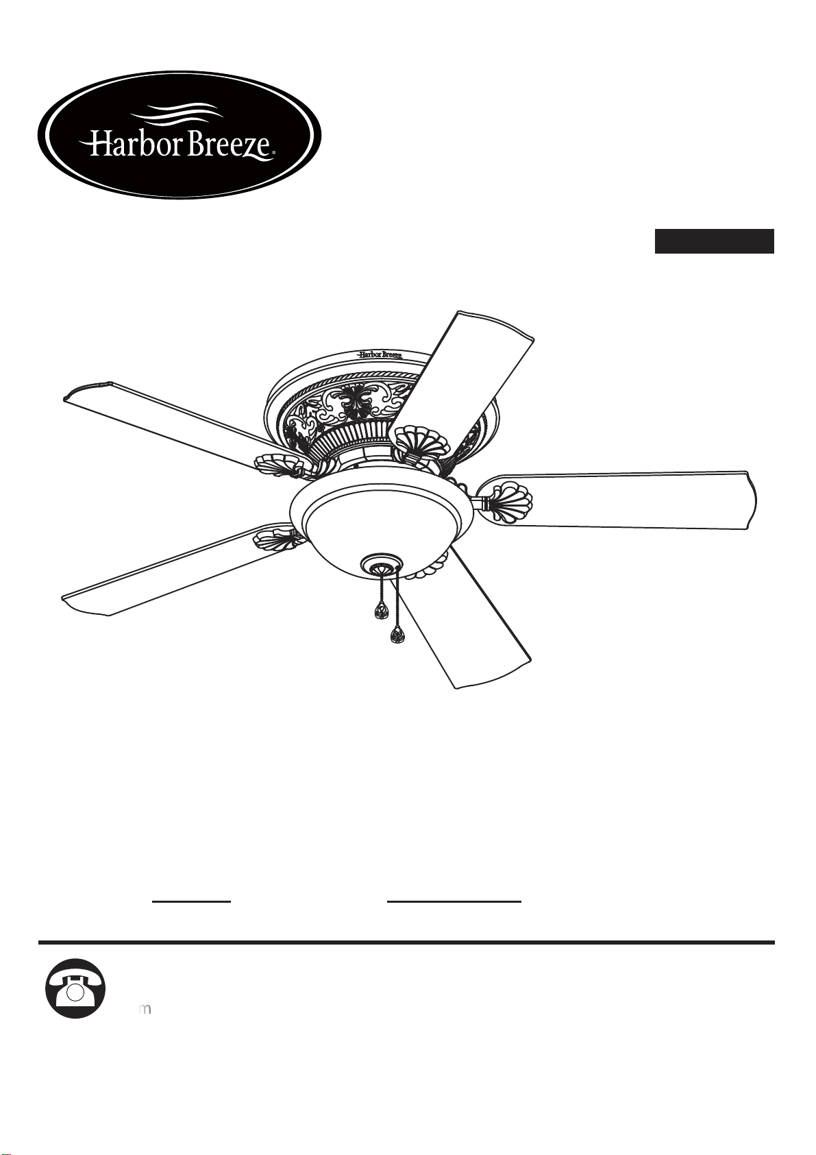
ITEM #3415243
MODEL #L1901-WH
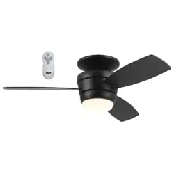
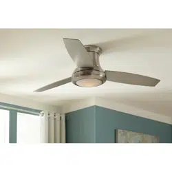
LYNSTEAD CEILING FAN
Harbor Breeze
®
and logo design are
trademarks or registered trademarks of
LF, LLC. All rights reserved.
1
Español p. 17
ATTACH YOUR RECEIPT HERE
Serial Number
Purchase Date
SM20627
Questions, problems, missing parts? Before returning to your retailer, call our customer
service department at 888-251-1003, 8 a.m. - 8 p.m., EST, Monday - Sunday. You could
also contact us at [email protected] or visit www.lowespartsplus.com.

TABLE OF CONTENTS
2
Preparation .......................................................................................................................
Initial Installation Instructions ...........................................................................................
Wiring Instructions ............................................................................................................
Final Installation Instructions ............................................................................................
Operation Instructions ......................................................................................................
Care and Maintenance .....................................................................................................
Troubleshooting ...............................................................................................................
Limited Lifetime Warranty ...............................................................................................
Replacement Part List ......................................................................................................
Safety Information ............................................................................................................
4
Package Contents ............................................................................................................
Hardware Contents ...................................................................................... ...................
3
4
5
6
8
9
13
13
14
15
16
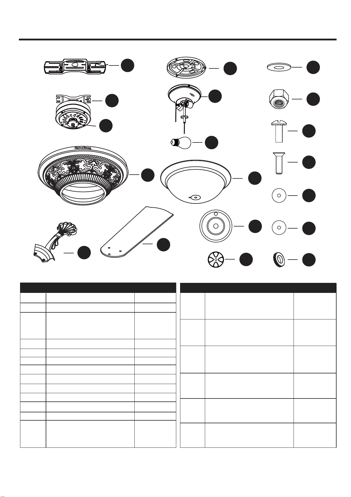
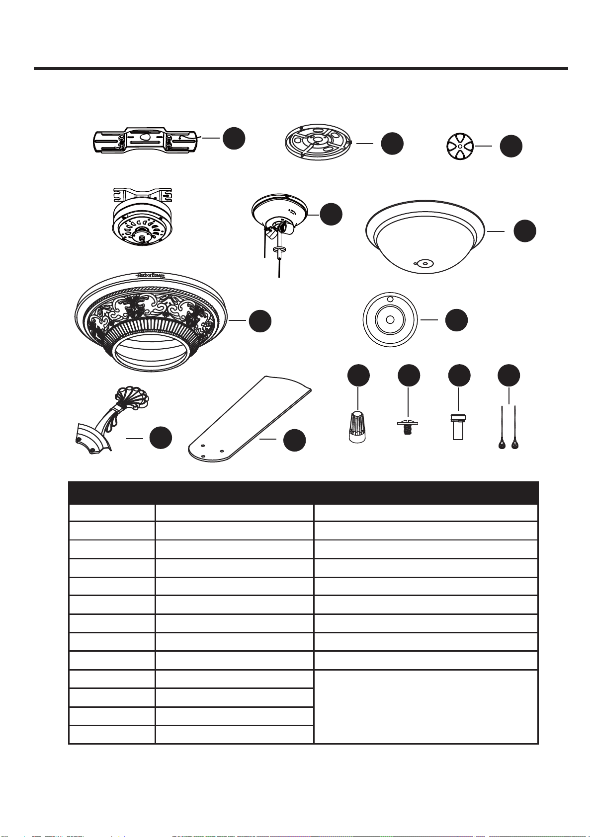
PACKAGE CONTENTS
A1
1
1
1
B
C
D
Mounting Bracket
Motor Body
Mounting Plate
(Preassembled to motor
body (B))
3
PART DESCRIPTION QUANTITY
4N
3O
3P
1Q
1R
1S
Hex Nut
(Preassembled on
Mounting Bracket (A))
Metal Washer
(Preassembled on
Mounting Bracket (A))
Mounting Screw
(Preassembled on Switch
Housing Plate(C))
Light Kit Mounting Screw
(Preassembled on Switch
Housing (G))
Silicone Washer
(Preassembled on Light
Kit (H))
Metal Washer
(Preassembled on Light
Kit (H))
Manual Nut
(Preassembled on Light
Kit (H))
Finial
Finial Cap
Motor Housing
5
5
1
F
G
E
Switch Housing
Blade
Blade Iron
1
1
I
H
Glass Bowl
Light Kit
2J
1K
1L
4M
Bulb
A
B
C
D
E
H
G
F
I
N
M
O
P
Q
R
K
L
S
J
PART DESCRIPTION QUANTITY
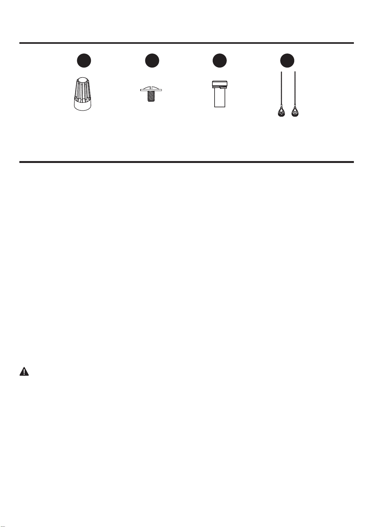
Wire Nut
Qty. 4
Blade Screw
Qty. 15 + 1 extra
Motor Screw
Qty. 10 + 1 extra
Fob
Qty. 2
4
HARDWARE CONTENTS
SAFETY INFORMATION
(not shown actual size)
AA BB CC DD
READ AND SAVE THESE INSTRUCTIONS
Please read and understand this entire manual before attempting to assemble, operate or install the product.
. All electrical connections must comply with local codes, ordinances or the National Electric Code (NEC).
Contact your municipal building department to inquire about your local codes, permits and/or inspections.
. Turn off electricity at main fuse box (or circuit breaker box) before beginning installation by removing fuse
or by switching off circuit breaker.
. Do not connect this fixture to an electrical system that does not provide a means for equipment grounding.
Never use a fixture in a two-wire system that is not grounded.
. If you are not sure your lighting system has a grounding means, do not attempt to install this fixture. Contact
a qualified, licensed electrician for information regarding proper grounding methods as required by the local
electrical code in your area.
. Make sure the installation site you choose allows a minimum clearance of 7 ft. from the blades to the floor
and at least 30 in. from the ends of the blades to any obstruction.
. If a dimmer control switch is used with this fixture, obtain professional advice to determine the correct type
and electrical rating required.
. The lighting fixture must be positioned so there is at least 1.64 ft. between the bulb and any illuminated
surface.
. For supply connections, if the conductor of a fan is identified as a grounded conductor, then it should be
connected to a grounded conductor power supply. If the conductor of a fan is identified as an ungrounded
conductor, then it should be connected to an ungrounded conductor power supply. If the conductor of a fan
is identified for equipment grounding, then it should be connected to an equipment-grounding conductor.
. Installing a fixture into an electrical system without a proper grounding means could allow metal parts of the
fixture to carry electrical currents. If any of the fixture wires, wire connections or splices are broken, cut or
loose during the mounting or normal operation of the fixture, under such conditon, anyone coming in contact
with the fixture is subject to electrical shock, which could cause serious injury or death.
. Connection of the bare or green fixture ground wire to the black or white house wires may allow metal parts
of the fixture to carry electrical currents. Under this condition anyone coming in contact with the fixture will
receive electrical shock, which could cause serious injury or death.
. Be careful not to damage or cut the wire insulation (covering) during fixture installation. Do not permit wires
to have contact with any surface having a sharp edge. Doing so may damage or cut the wire insulation,
which could cause serious injury or death from electric shock.
DANGER
5
WARNING
CAUTION
PREPARATION
Estimated Assembly Time:
and Wrench.
6
INITIAL INSTALLATION INSTRUCTIONS
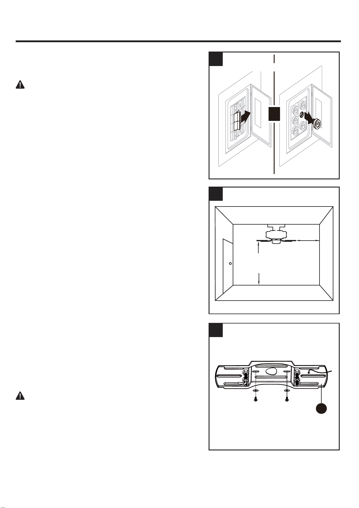
This fan was designed to be mounted only on flat
ceilings and can be used on ceilings less than 8 feet
high (blades should be a minimum of 7 feet from the
floor. It is requred at least 30 inch from blade tip to
nearest wall or obstruction).
Fan mounting options:
2..
2
3
1
7 ft. MIN.
30 IN.
MIN.
DANGER:
Failure to disconnect power supply prior to
1.
Turn off circuit breakers and wall switch to the fan supply
line leads.
installation may result in serious injury or death.
or
T
Turn Off Power Source
3.
Check existing outlet box (not included) to ensure it is
securely fastened to at least two points in a structural
ceiling member and can support the full weight of the fan.
Once verified, install mounting bracket (A) to the outlet
box using the screws and washers provided with the
outlet box.
DANGER:
A loose outlet box can cause the fan to
wobble and increase the fan’s potential to fall, which
could result in serious injury or death.
A
7
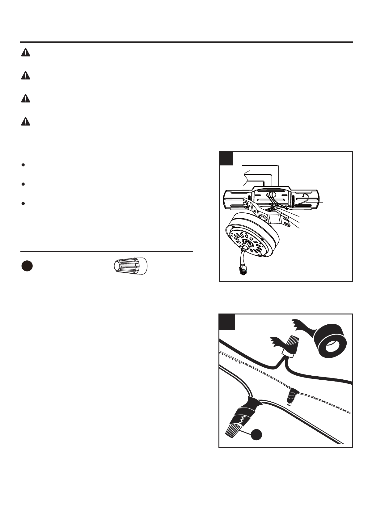
4. Remove the hex nuts (M) and metal washers (N) from
the threaded rods on the mounting bracket (A). Hang
the motor body (B) onto the hook from the mounting
bracket (A). This will allow for hands-free wiring.
INITIAL INSTALLATION INSTRUCTIONS
A
N
M
B
4
8
WIRING INSTRUCTIONS
1. Make wire connections as in the wiring diagram.
Connect BLACK and BLUE wires from fan to BLACK
(live) wire from house.
Connect WHITE wire from fan to WHITE (Neutral) wire
from house.
Connect GREEN (GROUND) wires from mounting
bracket (A) and motor body (B) to GREEN (GROUND)
from house.
1
GREEN(GROUND)
BLACK
WHITE
GREEN
(GROUND)
WHITE
BLACK
BLUE
AA
Hardware Used
Wire Connector x 3
2.
Wrap electrical tape (not included) around each
wire
connector and make sure no bare wire or wire strands
are visible after making connections. Then, turn wires
upward and carefully push them into the outlet box;
make sure the WHITE and GREEN connections are on
one side and the BLACK connections are on the other
side.
WARNING: To avoid possible electrical shock, be sure electricity is turned off at the main fuse
box before hanging.
WARNING: If you are not sure if the outlet box is grounded, contact a licensed electrician for
advice, as it must be grounded for safe operation.
WARNING: If house wires are different colors than referred to in the following steps, stop
immediately. A professional electrician is recommended to determine proper wiring.
WARNING: If you feel that you do not have enough electrical wiring knowledge or experience,
have your fan installed by a licensed electrician.
AA
2
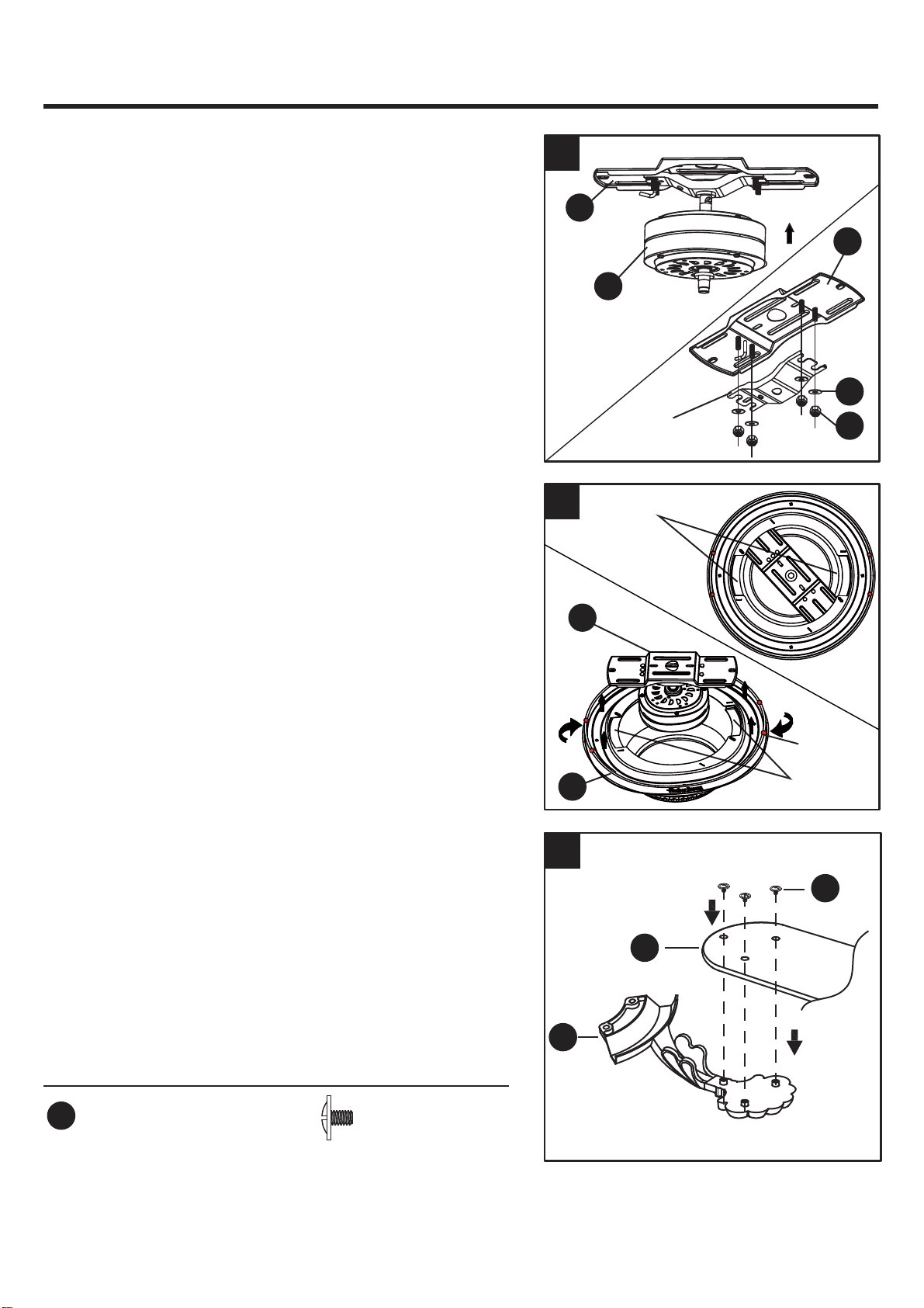
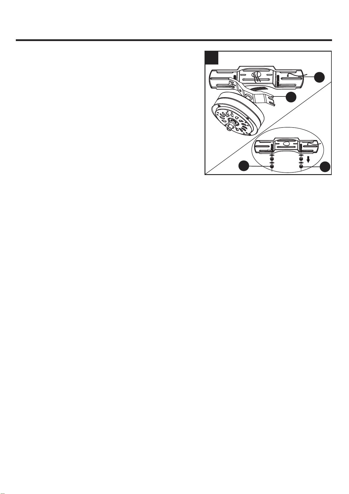
1. Lift the motor body (B) onto the mounting bracket (A),
making sure not to break away any wire connections,
and allow the four threaded rods from the mounting
bracket (A) to insert into rubber grommets on the
motor bracket from the motor body (B). Attach the
hanger bracket to mounting bracket (A) using the
metal washers (N) and hex nuts (M) removed
previously. Tighten the hex nuts with a wrench (not
included).
2. Raise the motor housing (D) up, align the four dot
labels on the motor housing (D) with the mounting
bracket (A), place the mounting bracket (A) onto the
recesses on the motor housing (D) properly, then
rotate the motor housing (D) clockwise until the
mounting bracket (A) slide into the slot hole inside the
motor housing (D).
9
FINAL INSTALLATION INSTRUCTIONS
Motor Bracket
Recesses
Recesses
dot label
A
A
A
D
B
N
M
11
2
3. Position blade iron (E) under blade (F). Secure them
with three blade screws (BB). Do not tighten blade
screws (BB) until three are in place. Then, tighten
each blade screw (BB) starting with the center blade
screw (BB). Repeat for all blade assemblies.
Hardware Used
x 15
BB
Blade Screw
3
BB
F
E
10
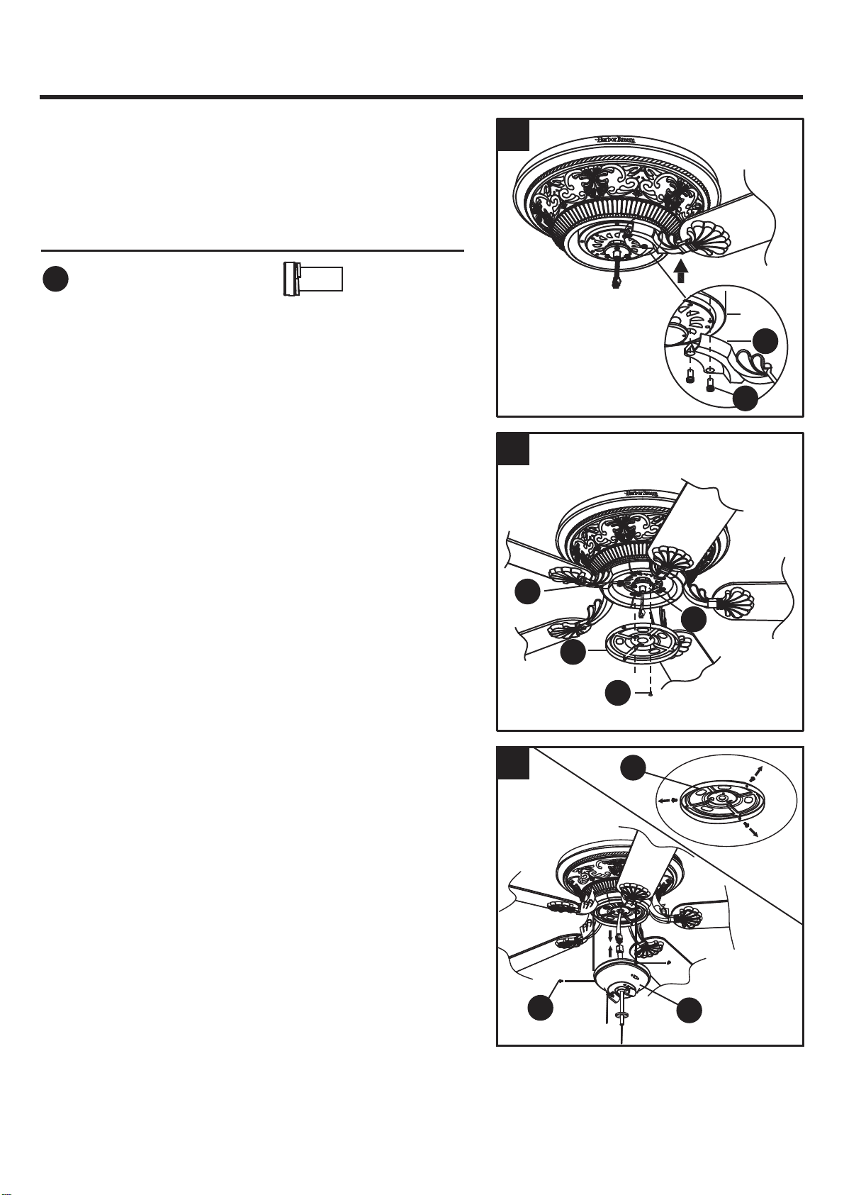
4. Align the holes between the blade iron (E) and motor.
Install the blade assembly to the motor using motor
screws (CC), and partially tighten. Repeat for the
remaining blade assemblies. Securely tighten all motor
screws (CC).
5. Remove one of the mounting screws (O) preinstalled
on the mounting plate (C) and loosen (do not remove)
the other two. Insert the wires from the motor body (B)
through the center hole in the switch housing (G).
Attach the switch housing (G) to the mounting plate (C)
by placing the keyslot holes from the switch
housing (G) onto the two protruding screw heads on
the mounting plate (C). Twist the switch housing (G)
until the screw heads engage the keyslots. Install
mounting screws (O) into the closed hole in the switch
housing (G). Tighten all mounting screws (O) to
complete attachment of the switch housing (G).
Hardware Used
x 10
CC
Motor Screw
6. Remove the three screws (P) preinstalled on the
switch housing (G). Attach the connector from the
light kit (H) to the connector from the motor body.
Align the three holes between the light kit (H) and
the switch housing (G). Re-install the switch housing
screws (P) to attach the light kit (H) to the switch
housing (G).
4
E
Motor
5
O
G
C
G
B
6
FINAL INSTALLATION INSTRUCTIONS
CC
P
H
11
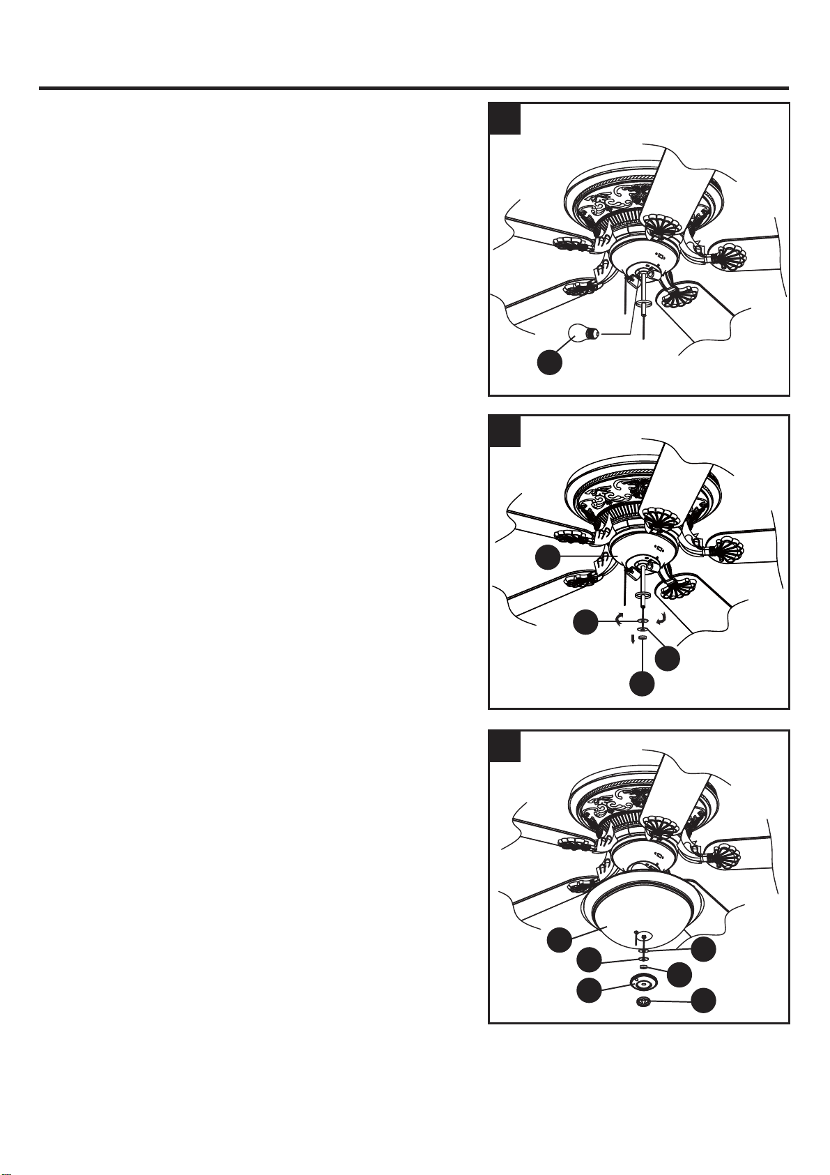
8
.
Remove and retain the silicone washer (Q), metal
washer (R) and manual nut (S) from the threaded rod
on the light kit (H).
9
.
Lift the glass bowl (I) up to the light kit (H), allowing
the threaded rod to go through the center hole in the
bottom of the glass bowl (I). While holding the glass
bowl (I), guide the pull chains through the appropriate
holes on the bottom of the glass bowl (I). Place the
silicone washer (Q), metal washer (R) and the
manual nut (S) onto the rod and tighten securely.
Guide the pull chains through the appropriate holes
on the finial cap (K). Attach the finial cap (K) to
the glass bowl (I) and tighten them using the
finial (L).
7
.
Install the two bulbs (J) into each socket.
7
FINAL INSTALLATION INSTRUCTIONS
9
8
I
R
Q
S
L
H
K
Q
R
S
J
12
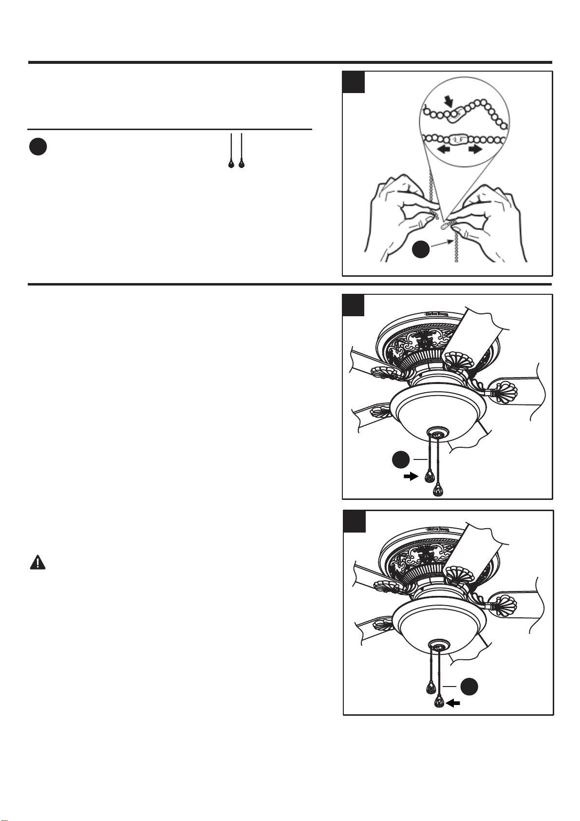
OPERATION INSTRUCTIONS
1. The fob (DD) marked with a fan image is for motor
speed control: High, Medium, Low and Off. Pull once
for each position.
2. The fob (DD) marked with a lamp image controls the
light either On or Off with each pull of the chain.
WARNING:
Please do not change to wall control or
remote control.
2
DD
1
DD
9
DD
9
.
Connect the fobs (DD) to the appropriate pull chains.
Hardware Used
x 2
DD
Fob
FINAL INSTALLATION INSTRUCTIONS
13
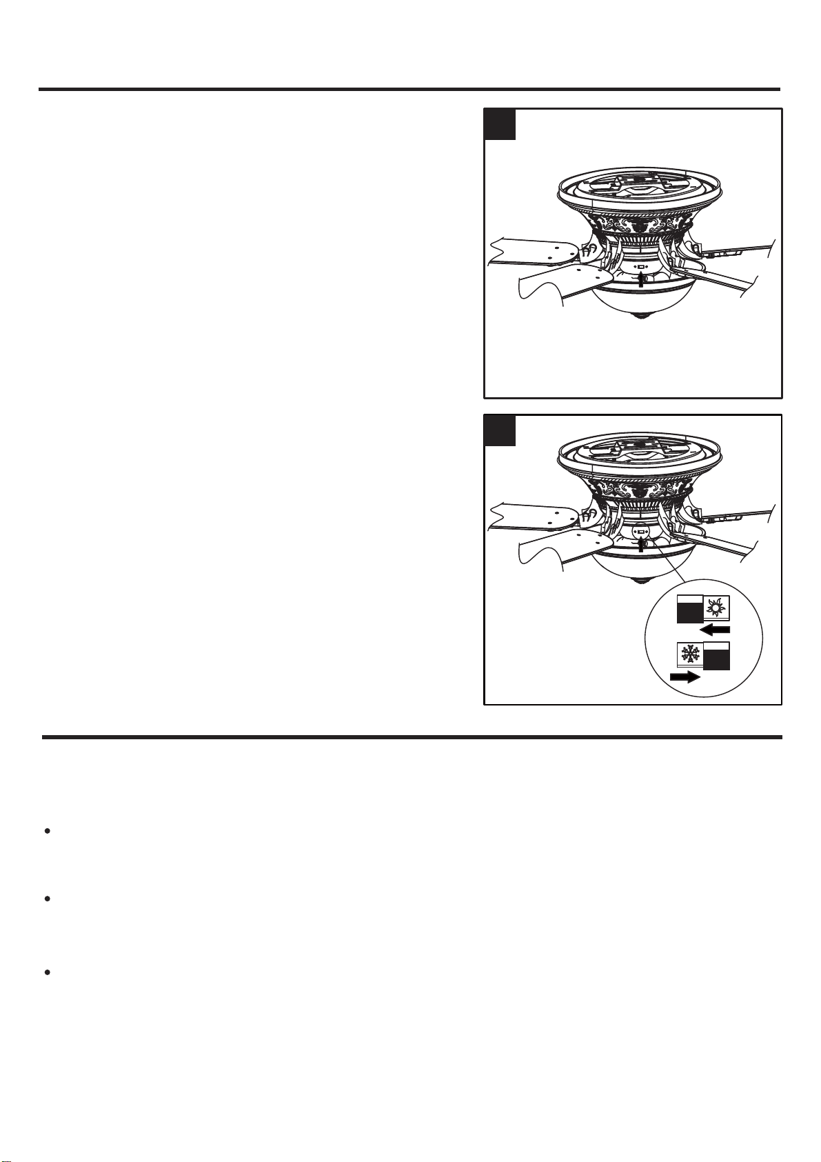
4
.
In warmer weather, counterclockwise rotation
creates a downward air flow, which cools the air.
Push the switch LEFT and see a SUN icon.
In cooler weather, clockwise rotation creates an
upward air flow, which moves hot air from the ceiling
into the room. Push the switch RIGHT and see a
SNOWFLAKE icon.
CARE AND MAINTENANCE
Important: Shut off main power supply before beginning any maintenance. Do not use water or a
damp cloth to clean the ceiling fan.
Bulb Replacement: Use two (2) 5.5 watt max type A-15 LED bulbs CFL bulbs are not
recommended for this item.
At least twice each year, tighten all screws and lower canopy motor housing to check mounting
bracket screws and hex nuts..
Clean fan housing with only a soft brush or lint-free cloth to avoid scratching the finish. Clean
blades with a lint-free cloth. You may occasionally apply a light coat of furniture polish to wood
blades for added protection.
OPERATION INSTRUCTIONS
4
3. When the season changes, you may want to change
the direction in which the fan spins. To switch between
clockwise and counterclockwise rotation, flip the fan
reversal switch.
NOTE: Wait for fan to stop before reversing the switch.
3
14
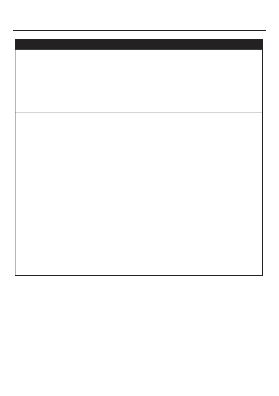
TROUBLESHOOTING
Fan sounds
noisy.
Fan wobbles.
Light does
not work.
PROBLEM
POSSIBLE CAUSE
CORRECTIVE ACTION
1. Hex nuts are loose.
Fan does
not start.
2. Normal noise.
3. Wire connectors inside switch
housing rattling.
4. Cracked blade.
5. Faulty light bulb installation.
6. Glass is not secure.
1. Tighten all hex nuts with wrench securely.
2. Allow "break-in" period of 24 hours. Most noises
associated with a new fan will disappear after this period.
3. Check to make sure wire connectors in switch housing
are not rattling against each other or against the interior
wall of the switch housing.
4. Replace blades.
5. Check to be sure light bulb is tight in socket and not
touching glass shade.
6. Secure the glass.
3. Blades are loose.
4. Blade holders incorrectly attached
and loose.
5. Fan blade out of balance.
6. W
obble appears when changing fan
speed.
3. Check that all blades are screwed firmly into blade holders.
1. Hanger bracket and/or ceiling outlet
box is not securely fastened.
1. Tighten the hanger bracket screws to the outlet box, and/or
secure outlet box.
2. Hex nuts are loose.
2. Tighten all hex nuts with wrench securely.
4. Check to be sure the fan blade flanges sit firmly and
uniformly to the surface of the motor hub. If flanges are
seated incorrectly
, loosen the flange screws and retighten.
5. If blade wobble is still noticeable, interchanging two
adjacent (side by side) blades can redistribute the weight
and possibly result in smoother operation, or you can use
supplied balancing kit to balance blades.
6. When switching from medium to low speed, you may
notice some fan wobble. When the fan stabilizes at low
speed, wobble will disappear
.
1. Power turned off, fuse blown, or
circuit breaker tripped.
2. Loose wire connections or wrong
connections.
3. Motor reversing switch not engaged.
4. Pull chain switch not "on".
1.
Turn power on, replace fuse, or reset breaker.
2a. Turn power off and loosen motor housing, check all
connections according to section "WIRING
INSTRUCTIONS".
2b. Check the plug connection in the switch housing.
3. Push switch firmly right or left (up or down). Fan will not
operate when switch is in the middle.
4. Pull switch chain.
1a. Wrong wire connection.
1a. Refer to Step 1, page 8 to ensure all wire connections
were done correctly.
1b. Bulb is burned out. 1b. Replace the bulbs.

15
LIMITED LIFETIME WARRANTY
The manufacturer warrants this fan to be free from defects in workmanship and material present at
time of shipment from the factory for life (with limitations) from the date of purchase. This warranty
applies only to the original purchaser. The manufacturer agrees to correct such defect at no charge
or, at our option, replace the ceiling fan with a comparable or superior model.
To obtain warranty service, present a copy of your sales receipt as proof of purchase. All cost of
removal and reinstallation are the expressed responsibility of the purchaser. Any damage to the
ceiling fan by accident, misuse or improper installation, or by affixing accessories not produced by
this warranty, are at the purchaser’s own responsibility. The manufacturer assumes no responsibility
whatsoever for fan installation during the limited lifetime warranty. Any service performed by an
unauthorized person will render the warranty invalid.
Due to varying climatic conditions, this warranty does not cover changes in brass finish, rusting,
pitting, tarnishing, corroding or peeling. Brass finish fans maintain their beauty when protected from
varying weather conditions. Any glass provided with this fan is not covered by the warranty.
Any replacement of defective parts for the ceiling fan must be reported within the first year from the
date of purchase. For the balance of the warranty, call our customer service department at
888-251-1003 for return authorization and shipping instructions so that we may repair or replace the
ceiling fan. Any fan or parts returned improperly packaged is the sole responsibility of the purchaser.
There is no further expressed warranty. The manufacturer disclaims any and all implied warranties.
The duration of any implied warranty which can not be disclaimed is limited to the lifetime limited
period as specified in our warranty. The manufacturer shall not be liable for incidental, consequential
or special damages arising at or in connection with product use or performance except as may other-
wise be accorded by law. This warranty gives you specific legal rights, and you also have other rights
which vary from state to state. This warranty supersedes all prior warranties.
NOTE: A small amount of “ wobble ” is normal and should not be considered a defect.
A
D
E
H
G
F
I
K
L
REPLACEMENT PART LIST
16
AA BB CC DD
For replacement parts, call our customer service department at 888-251-1003, 8 a.m. - 8 p.m., EST,
Monday - Sunday. You could also contact us at [email protected] or visit www.lowespartsplus.com.
A Mounting Bracket
D Motor Housing
E Blade Iron
F Blade
G Switch Housing
H Light Kit
I Glass Bowl
K Finial Cap
L Finial
AA Wire Nut
Blade Screw
Motor Screw
Fob
BB
CC
DD
Part Description Part#
Printed in China
A102-0374005
A113-0375213
A143-0193213
A141-0244001
A121-0458213
A187-0225213
A182-0230001
A183-0031213
A186-0109213
B168-0598213