Loading ...
Loading ...
Loading ...
STEP3: Checksparkignitioncircuit,
Electricalshockhazard.Ignition circuit generates
over 10,000volts. TurnOFFelectricalpower
supplyat servicepanelbeforemakingelectrical
connections. Failureto do so could result in death
or seriousinjury.
Disconnectignitioncableat SPARKterminalonmodule.
Energizemoduleandlistenfor audiblesparkingnoise.
Whenoperatingnormally,thereshouldbebuzzingnoise
turnsonandofftwicepersecondfor durationof 1-7
seconds,dependingonmodel.
STEP4: Verifypilotandmainburnerlightoff.
• Initiatecallfor heat.Turnthermostataboveroom
temperature.Ignitionsequencemaybedelayedby
thermalpurgeuntilboilerwatertemperatureisbelow
140°F(60°C)
• Watchpilotburnerduringignitionsequence.
-- Verifyignitionsparkcontinuesafterpilotislit.
-- Verifypilotlightsandsparkstops,verifymain
burnerdoesnotlight.
• If so,ensureadequateflamecurrentasfollows.
-- Turnoff boilerat circuitbreakerorfusebox.
-- Cleanflamerodwithemerycloth.
-- Verifyelectricalconnectionsarecleanandtight.
Replacedamagedwire..
-- Checkfor crackedceramicinsulator,whichcan
causeshortto ground,andreplaceigniter-sensorif
necessary.
-- At gasvalve,disconnectmainvalvewirefromMV
terminal.
-- Turnon powerandsetthermostatto callfor heat.Pilot
shouldlight,mainburnerwillremainoff becausemain
valveactuatorisdisconnected.
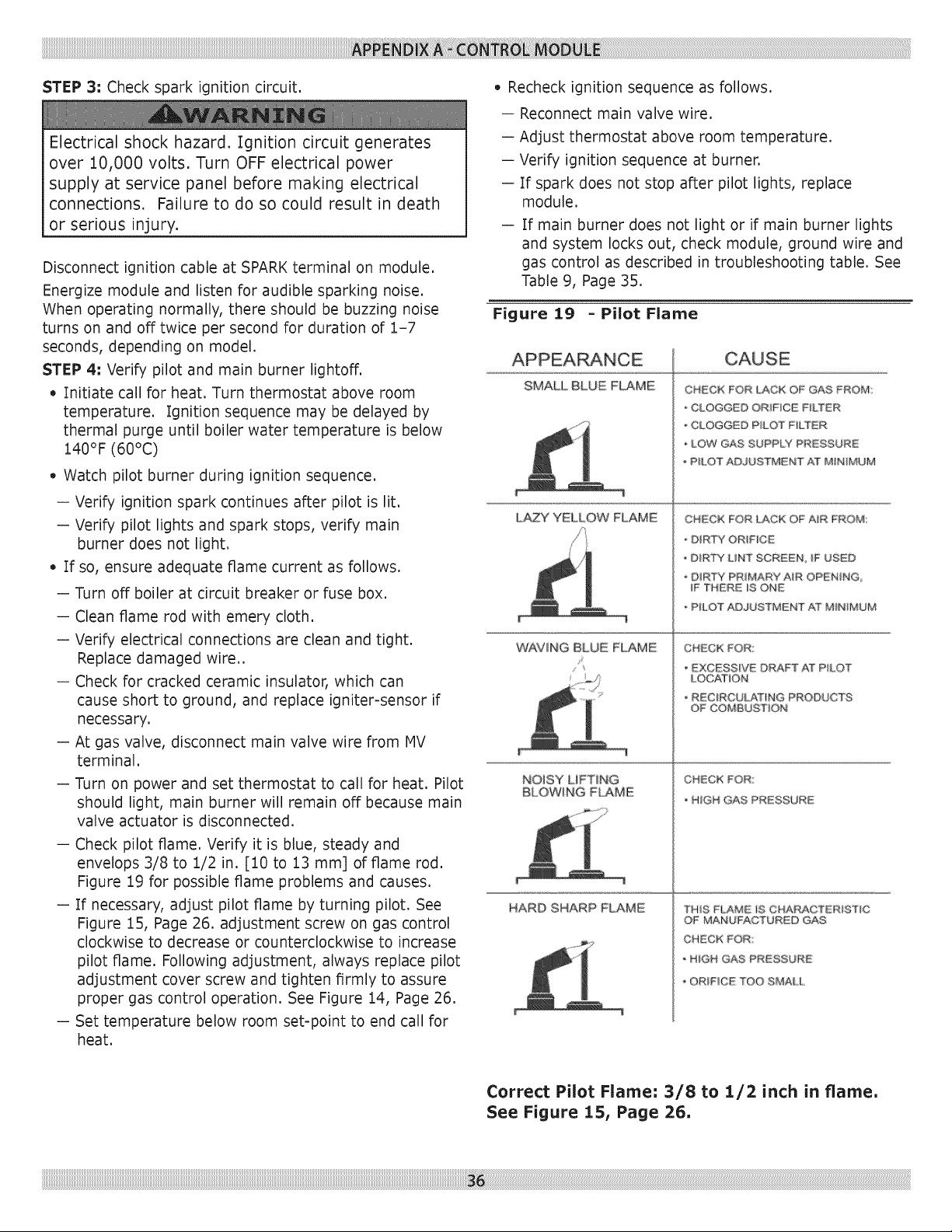
-- Checkpilotflame.Verifyit is blue,steadyand
envelops3/8to 1/2in. [10to 13mm] offlamerod.
Figure19for possibleflameproblemsandcauses.
-- If necessary,adjustpilotflamebyturningpilot.See
Figure15,Page26.adjustmentscrewongascontrol
clockwiseto decreaseorcounterclockwiseto increase
pilotflame.Followingadjustment,alwaysreplacepilot
adjustmentcoverscrewandtightenfirmlyto assure
propergascontroloperation.SeeFigure14,Page26.
-- Settemperaturebelowroomset-pointto endcallfor
heat.
• Recheckignitionsequenceasfollows.
-- Reconnectmainvalvewire.
-- Adjustthermostataboveroomtemperature.
-- Verifyignitionsequenceat burner.
-- If sparkdoesnotstopafterpilotlights,replace
module.
-- If mainburnerdoesnotlightor if mainburnerlights
andsystemlocksout, checkmodule,groundwireand
gascontrolasdescribedin troubleshootingtable.See
Table9, Page35.
Figure 19 - Pilot Flame
SMALL BLUE FLAME
L_Y YELLOW FLAME
WAVING BLUE FLAME
/ 4
NOISY LiFTiNG
BLOWING FLAME
HARD SHARP FLAME
CHSCK FOR LAC_ OF GAS FROM:
-CLOGGED ORIFICE FILTER
• CLOGGED PILOT' F&TER
LOW GAS SUPPLY PRESSURE
, P&OT ADgUSTMENT AT MiNiMUM
CHECK FOR LACK OF A_R FROM::
DIRTY ORiFiCE
D_RTY UNT SCREEN iF USED
' D_RT Y PRm[_AR_ A_R O_i_N_NG
IF THZRE iS ONE
* PfLOT ADJUSTMENT AT MINIMUM
CHECK FOR:
EXCESSIVE DRAFT AJTP&OT
LOC_Jt_ON
RECiRCULAT_NG PRODUCTS
OF COMBUS:T_ON
CHECK FOR
HiGH GAS PRESSURE
THIS FLAME _S CHARACTERiSTiC
©F MAiNUFACTURED GAS
CHECK FOR
, HIGH GAS PR£SSURE
o ORIFICE TOO SMALL
Correct Pilot Flame= 3/8 to 1/2 inch in flame.
See Figure 15, Page 26,
Loading ...
Loading ...
Loading ...