Loading ...
Loading ...
Loading ...
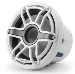
JL AUDIO M 6-8IB 5
All specifications are subject to change without notice.
TRANSFLECTIVE RGB LED LIGHTING
Illuminated speaker models are equipped with our innovative Transflective™ RGB
LED lighting system (patent pending). Fully integrated into the speaker chassis, state-
of-the-art LED rings are positioned behind the woofer cones to produce vibrant accent
lighting that is remarkably smooth and even, with no hot spots. A cable harness located
between the woofer terminals includes wire leads for LED connections. Refer to the
table below for individual RGB wire connection info. Note: Wiring connections at each
speaker location are required for LED functionality.
Wire Color RGB LED Connection
Red Red RGB LED Negative (–)
Green Green RGB LED Negative (–)
Blue Blue RGB LED Negative (–)
Yellow Main RGB LED Positive (+12V)
Adjustable control of RGB lighting may be achieved with the use of an RGB lighting
controller (sold separately). Refer to the instructions of your RGB lighting controller for
specific connection info. Note: When selecting an RGB lighting controller, make sure
that the total amperage demands of all LED circuits does not exceed the output
capacity of the controller. Refer to the table below for the individual current draw
amounts and sum (add) the total. For optimal performance, we recommend using
the JL Audio marine lighting controller (MLC-RW).
RGB LED SPECIFICATIONS
Specification M6-8
LED Current Draw at 12V DC 486 mA
Recommended Fuse Value 750 mA
LED Voltage Range 10 - 14.4V DC
DIRECT LED WIRING
Alternatively, you may hard wire individual leads or a combination of leads to achieve
up to seven different LED color assortments. Refer to the table below for the wire colors
used to achieve specific LED colors.
LED Color Wire Color(s) Connection
Red Red
Combine selected wires
from all speakers and
connect to negative
ground or to the negative
(–) battery post.
Green Green
Blue Blue
Yellow Red and Green
Pink Red and Blue
Aqua Green and Blue
White Red, Green and Blue
Combine all YELLOW (+12V) leads together (parallel) and connect to a switched +12V
supply. See below for additional info.
LED WIRING CONSIDERATIONS
• Do not connect to 24V electrical systems.
• Do not connect the speakers’ LED lights to the vessel’s navigational
lighting circuits.
• For short-circuit protection, we recommend installing a fuse (not included) at
EACH speaker’s YELLOW (+12V) LED power connection lead. Refer to the
RGB LED Specifications table (at left) for recommended fuse ratings.
• We recommend a minimum of 16AWG wire size for each speaker’s LED
connection circuits.
• In addition to the above, we recommend activating the speakers’ LEDs thru
a cabin/interior lighting circuit that supplies +12V via an existing switch. If an
existing switched circuit is not available, you may install a dedicated toggle/
rocker style switch that will supply positive (+12V) power. Fuse this main +12V
connection according to the total amperage demands of all LED circuits.
Refer to the RGB LED Specifications table (at left) for individual current draw
amounts and recommended fuse ratings.
Loading ...
Loading ...
Loading ...