Loading ...
Loading ...
Loading ...
15
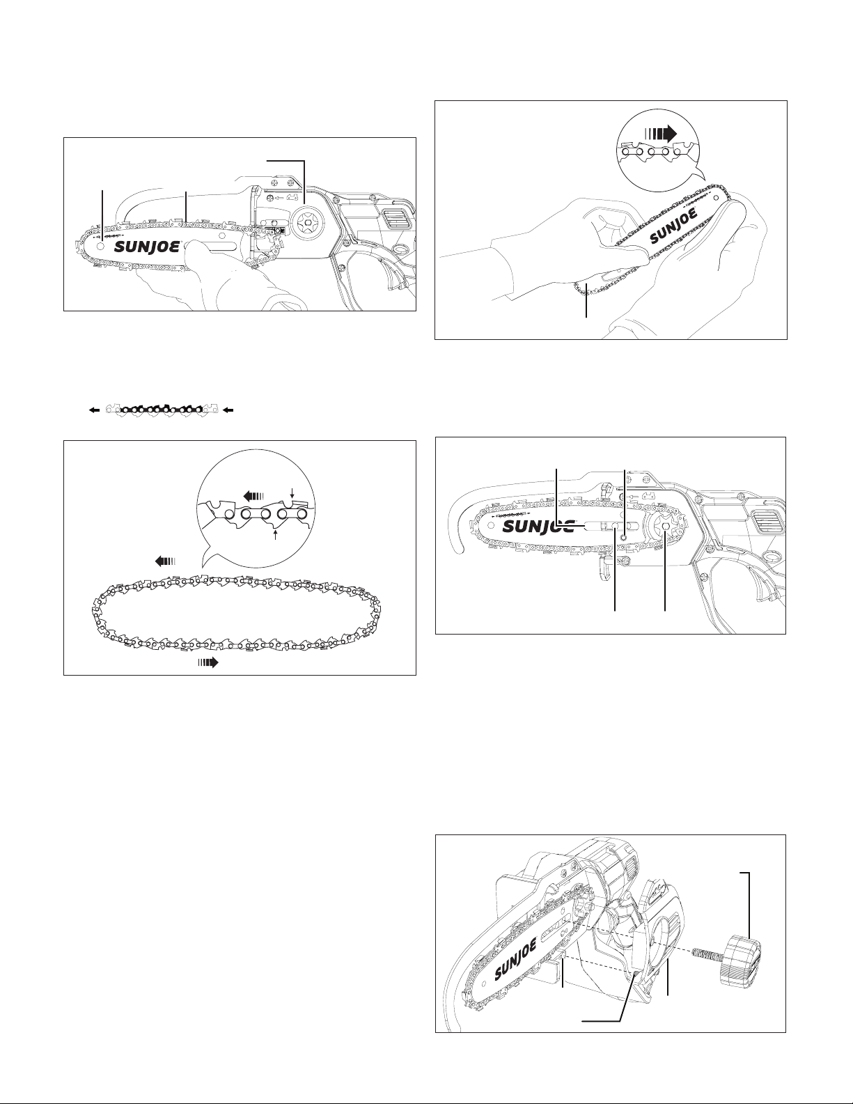
2. Remove the cutting bar and chain from the mounting
surface (Fig. 12).
3. Remove the old chain from the bar.
4. Lay out the new saw chain in a loop and straighten
any kinks. THE SHARP SIDE OF THE TEETH MUST
FACE AWAY FROM YOU IN THE DIRECTION OF THE
CHAIN ROTATION INDICATED ON THE GUIDE BAR
. If the teeth face backwards,
turn the loop over (Fig. 13).
5. Starting at the tip, mount the chain drive links into the
bar groove, leaving a loop at the back of the bar. The chain
will loosely t until it is placed on the sprocket
(Fig. 14).
NOTE: Make certain of the direction of the chain. If
the chain is mounted backwards, the saw will vibrate
abnormally and will not cut.
6. Hold the chain in position on the bar and place the loop
around the sprocket. Fit the bar against the mounting
surface so that the extruded piece on the mounting
surface is in the long slot of the bar and the adjusting pin
is in the chain tension pin hole (Fig. 15).
7. While keeping the bar and chain against the mounting
surface, adjust the chain tension as needed by adjusting
the chain tensioner screw with the supplied hex key
wrench. Turn the chain tensioner screw clockwise to
tightening the chain, or counter-clockwise to loosen the
chain (Fig. 4).
8. Replace the chain/sprocket end cover by inserting the
tab located on the bottom rst into the slot and position
the cover over the bar end. Tighten the end cover knob;
leave the bar loose enough to move slightly for tension
adjustment (Fig. 16).
R
Fig. 12
Guide bar
Cutting chain
Mounting surface
Fig. 13
Chain rotation
Sharp cutting edge
Chain drive link
R
Fig. 14
Loop
R
Fig. 15
Adjusting pin
SprocketExtruded piece
Slot
R
Fig. 16
Chain/sprocket
end coverTab
Slot
End cover knob
Loading ...
Loading ...
Loading ...