
www.kolpak.com 800-225-9916 2
Table of Contents
General Safety Information ............................................................................................. 3
Receiving Inspection ....................................................................................................... 4
Panel Count .................................................................................................................... 4
Panel Storage .............................................................................................................. 4-5
Panel Identification .......................................................................................................... 5
Site Preparation ........................................................................................................... 6-7
Cam Action Panel Fasteners ........................................................................................ 7-8
General Installation Guidelines ....................................................................................... 8
Screed Identification & Installation ............................................................................. 9-11
Floor Panel Installation ............................................................................................. 12-13
Floor Overlay Installation ............................................................................................... 14
Concrete & Tile Flooring ................................................................................................ 15
Wall Panel & Door Section Installation ..................................................................... 15-16
Ceiling Panel Installation ............................................................................................... 16
Split-Over Partition Wall/Ceiling .................................................................................... 17
Ceiling Support .............................................................................................................. 18
Interior/Exterior Ramps ................................................................................................. 19
Plug Buttons & Penetrations ......................................................................................... 20
Trim & Wainscoting Material ......................................................................................... 21
Threshold Installation .................................................................................................... 22
Door Sweep Adjustment ................................................................................................ 23
Adjustable Hinges ......................................................................................................... 24
Thermometer Testing & Recalibration ........................................................................... 25
Electrical Connections ................................................................................................... 26
Tapered Roof System ................................................................................................... 27
Membrane Roof System ........................................................................................... 28-31
Maintenance & Housekeeping ...................................................................................... 32
System Start-up Checklist ........................................................................................ 33-36
Warranty Information ..................................................................................................... 37
www.kolpak.com 800-225-9916 3
General Safety Information
Read this manual carefully before beginning the installation and operation of the unit.
Scan the QR Code below to view the Basic Walk-In Installation Service Video.
Special attention is required to all sections identified with the following warning and
caution notices:
WARNING
Text in a Warning box alerts you to a potential personal injury situation. Read each
Warning statement before proceeding and work carefully.
CAUTION
Text in a Caution box alerts you to a situation in which you could damage the unit. Read
each Caution statement before proceeding and work carefully.
Disregarding these special notices may result in personal injury and/or damage to the
unit.
Safety Notices:
Installation and maintenance/servicing are to be performed only by trained and
qualified personnel familiar with commercial walk-in products.
Ensure that all field wiring conforms to the equipment requirements and all
applicable local and national codes.
Disconnect all power sources before servicing the unit.
Sheet metal and coil surfaces have sharp edges. Use appropriate protective
gloves to prevent injury.
Use appropriate eye protection during installation and servicing.
www.kolpak.com 800-225-9916 4
Receiving Inspection
Check the shipment carefully and compare to the bill of lading. Account for all items
listed and inspect each container for damage. Carefully inspect for any concealed
damage. Report any shortages or damages to the carrier, note on the bill of lading, and
file a freight claim.
Damaged material cannot be returned to the manufacturer without prior approval. A
Return Material Authorization (RMA) must be obtained. Contact a sales representative
at 800-826-7036.
Panel Count and Hardware
Using the packing list and skid documentation, count the wall panels, corners, ceilings,
doors, and floors where applicable. Locate and verify the accessory and hardware
package(s).
WARNING
Do not attempt to lift the panels or accessories by yourself. Always have adequate
lifting equipment or manpower available to accomplish the task safely.
Do not unwrap the skids and leave the panels in a position that they could fall over or
blow over and cause an injury. Be sure that panels are adequately restrained at all
times.
CAUTION
Acids and oils on hands and fingers could discolor wall panel finish. Make sure to wear
appropriate gloves that are free from residue while handling wall and ceiling panels.
CAUTION
Make sure to store the panels as noted below if necessary to ensure that they are not
damaged prior to being installed.
Panel Storage
If the walk-in panels must be stored on a job site before installation, store them inside if
possible.
The PVC protective panel covering should only be removed after final assembly of the
walk-in. Gloves should be worn to prevent acids and oils on hands/fingers from creating
smudges on panel surface.
The panels may be stored on skids as received, provided the skids are on level surface
and kept free of moisture.
www.kolpak.com 800-225-9916 5
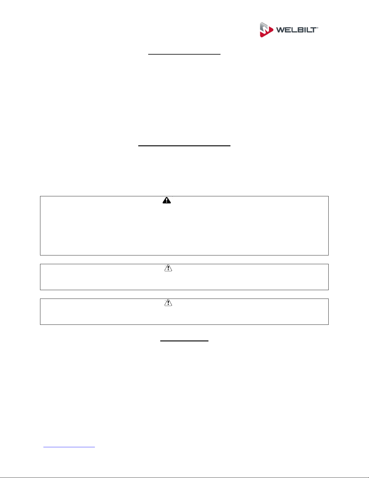
If the panels must be stored outside, store them on edge with the grooved side (female
rail) facing down. Kiln-dried wood spacers provide a ventilation gap to prevent moisture
stains from forming on the panels’ metal skins. Cover the panels with black plastic to
keep out sunlight and moisture. Be sure the plastic does not touch the ground, allowing
air circulation.
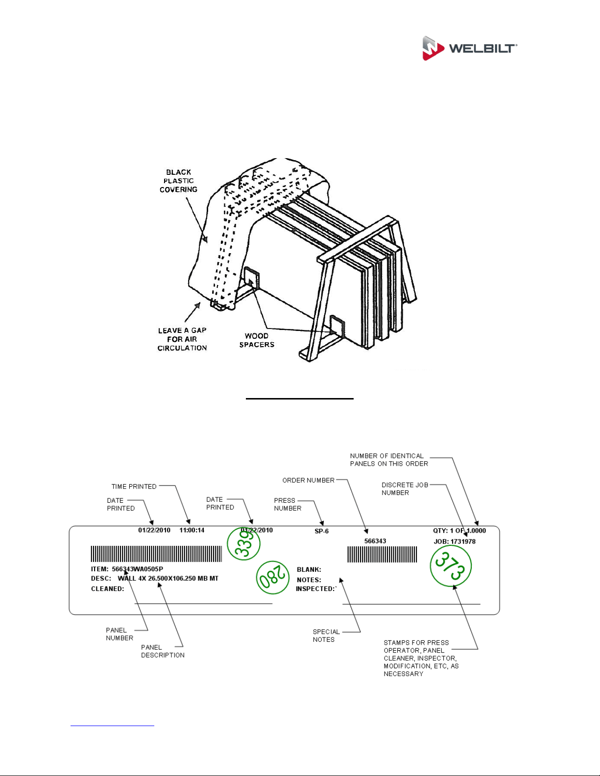
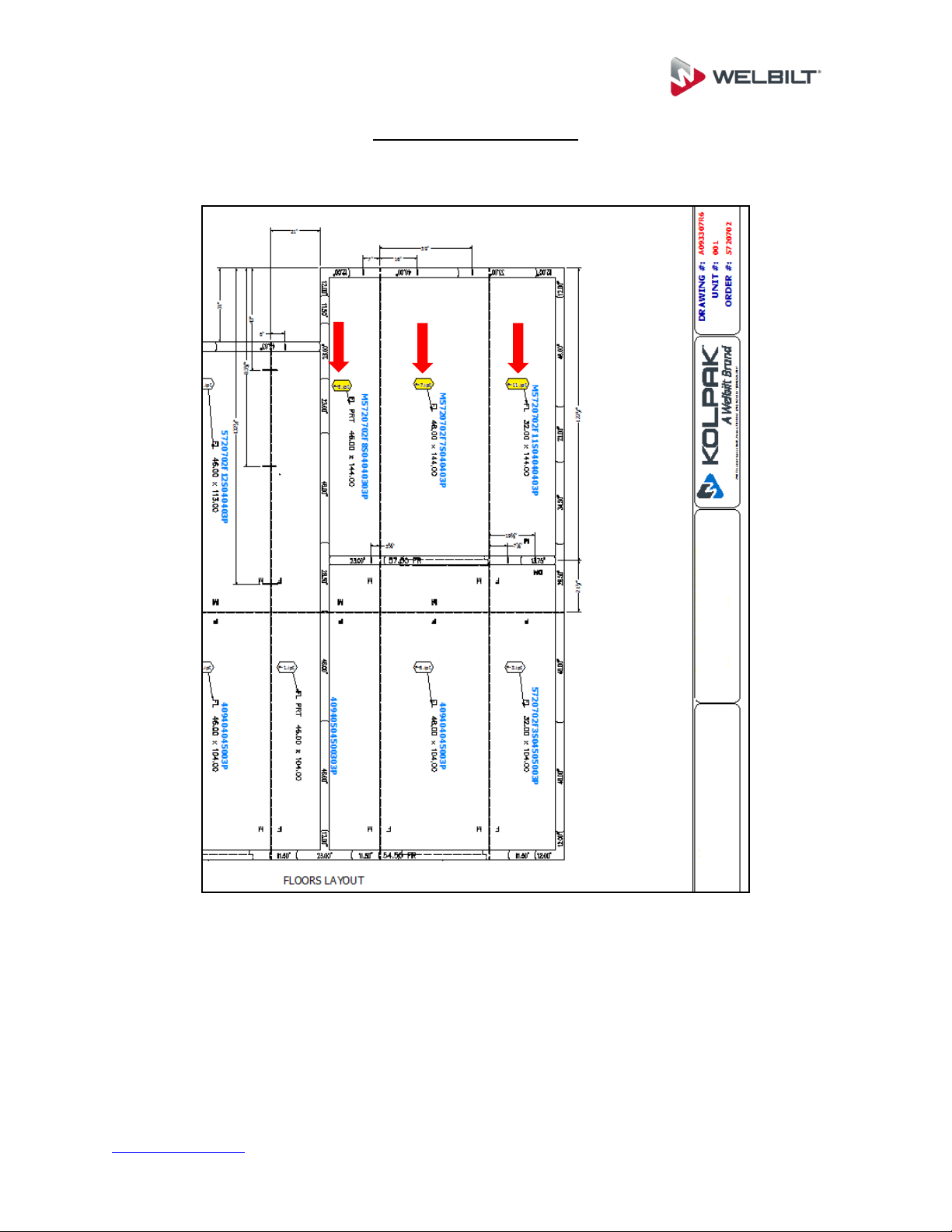
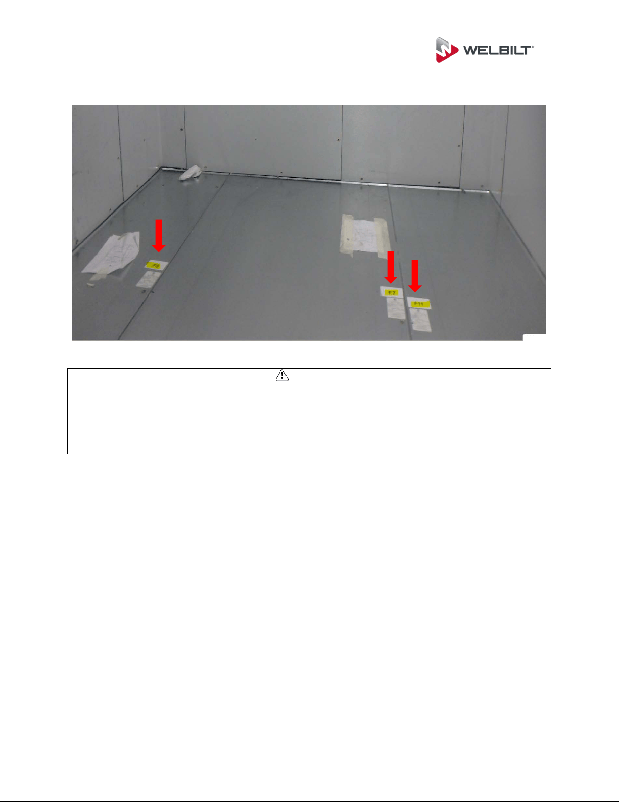
Panel identification
Each panel is labeled to aid in identification and proper placement. Panel item numbers
are referenced on the product assembly drawing showing proper location for intended
installation within the unit.
www.kolpak.com 800-225-9916 6
Site Preparation
CAUTION
Ensure that the area for installation is level and clear of all debris before beginning
assembly. If care is not taken to assure a level base, wall and ceiling panels will not
align properly, causing problems in installation and operation of door panels, and
potential performance issues due to escessive air leaks. The two recommended
techniques to level the floor area are self-leveling epoxy and/or asphalt shingles.
For concrete slabs, above grade is recommended. A slab below grade is not permitted.
A 2” minimum clearance is required between the unit and any adjacent structures to
allow for wall surface irregularities and for air circulation. Air circulation around the
walk-in of 5 CFM per 100 Sq. Ft. of wall area is recommended. Failure to allow for this
clearance and air flow may result in performance issues such as excesive moisture
and/or condensation in the unit or adjoining areas.
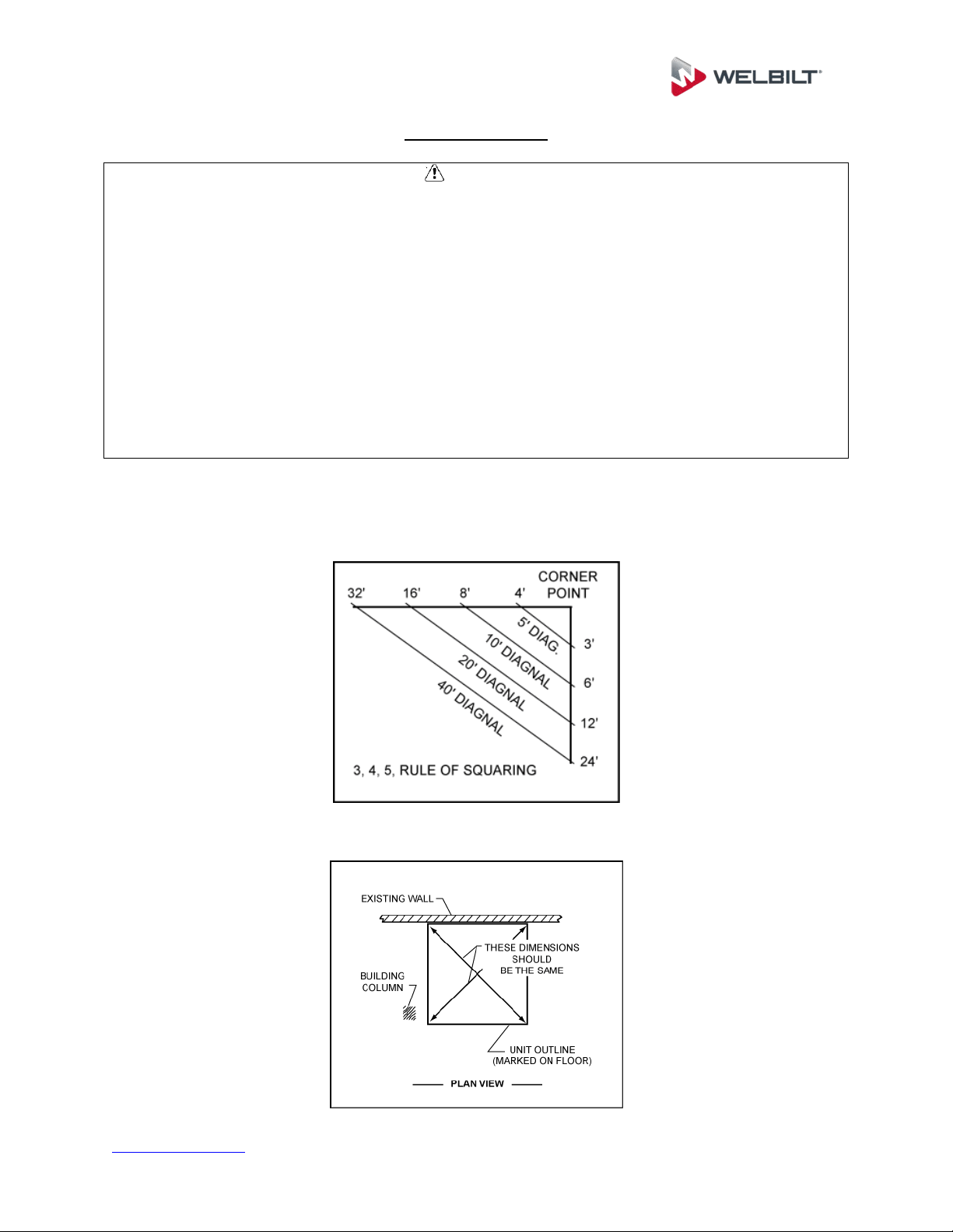
Using the supplied assembly drawing (in hardware box), mark the perimeter of
screed, wall, or floor sections on the existing building floor using a chalk line.
Perimeter lines must be square and parallel. Use the 3, 4, 5 rule of squaring.
After the first two lines, measure and establish the rest of the perimeter.
www.kolpak.com 800-225-9916 7
If the installation area is not level, find the high point of this perimeter line. The
floor, floor screed and wall must be leveled to this point.
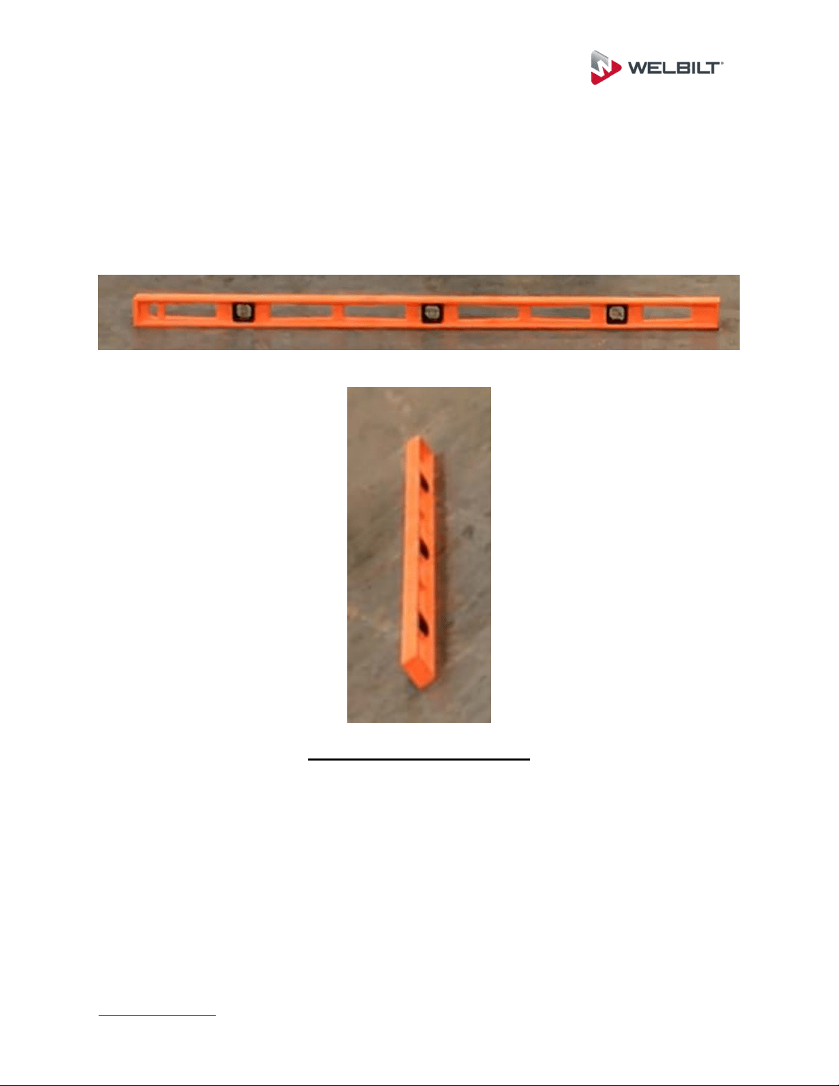
Use a 4’ level to determine floor levelness. Be sure to check both directions for
floor levelness.
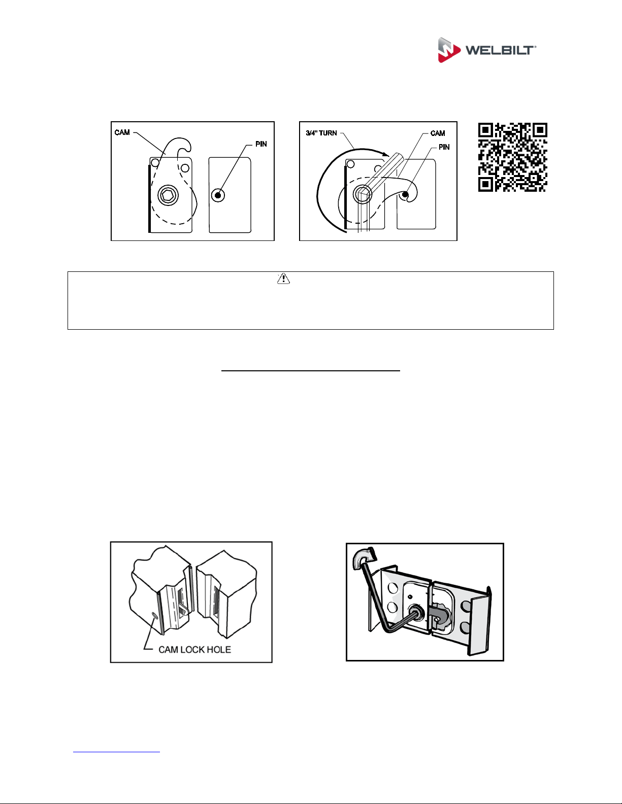
Cam Action Panel Fasteners
Before starting to assemble the unit, be sure to familiarize yourself with the operation of
the panel fasteners.
To operate the cam locks, insert a 5/16” hex wrench (packed in hardware box)
through the access hole in the panel interior skin, and into the hex opening in the
fastener. Turn the wrench clockwise approximately 3/4 of a turn to put the cam
hook into the locked position.
If a problem should occur, such as having to unlock a panel that was not properly
positioned, you must turn the handle counterclockwise until it stops, in order to
reset the cam position.
www.kolpak.com 800-225-9916 8
Scan the QR Code below to view Operating The Cam Lock Service Video.
CAUTION
Using a hammer to drive the hex wrench into the panel fastener can result in damaging
the interface surface, rendering the lock unusable. Clear the hole of any debris if the
wrench cannot be fully inserted with normal hand pressure.
General Installation Guidelines
All insulated panels have a tongue and a groove perimeter edge. This interlocking
design and the panel edge gaskets will result in an air-tight walk-in when installed
square and level. Refer to the assembly drawing for the general layout and specific
panel placement and markings.
The tongue side of the panel and cam lock holes is on the left of each seam when
viewed from the interior of the walk-in (standing on the inside and looking out). The
exact location of the tongue (M) and groove (F) for ceiling and floor panels, if required,
will be shown on the assembly drawing.
www.kolpak.com 800-225-9916 9
Screed Identification And Installation
There are many styles of screeds used in floorless walk-in coolers and freezers. The
types of screeds furnished with your unit will be identified on the unit assembly drawing.
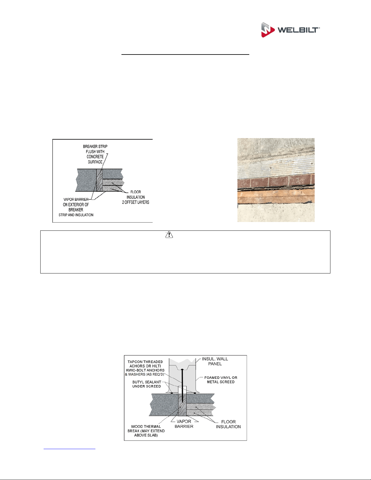
Breaker strips (thermal breaks) are used to prevent heat transfer between the
cooled side and the ambient side of a concrete floor. Without these thermal
barriers, heat transfer through the concrete layer is relatively rapid, causing a
greater likelihood of condensation and icing outside of the unit, as well as
increased energy consumption and cooling load on the refrigeration system.
CAUTION
When having a product installed with a thermal break, make sure that the contractor
leaves the top of the thermal break exposed for later inspection, not covered by
concrete. If there are performance issues after installation, it may be necessary to
inspect the position and condition of the thermal break.
Standard screeds are available in both vinyl (with integral floor coves) and metal
versions. Vinyl screeds cannot be used in outdoor applications due to potential
issues with UV degradation caused by sunlight. Most thermal breaks are
installed to be level with the concrete surface. Heights for vinyl screeds are 1.5”
or 4”, while metal screeds are available in various heights as necessary for the
application. Standard screeds are pre-cut with intended installation locations
shown on the assembly drawing.
www.kolpak.com 800-225-9916 10
U-shaped screeds are available for customers who desire to use a vinyl screed,
but need either a lower profile or need a special height finished unit, and would
prefer to use a standard sized wall panels. U-shaped screeds are factory cut to
length and mitered on the corners, with intended installation locations shown on
the assembly drawing.
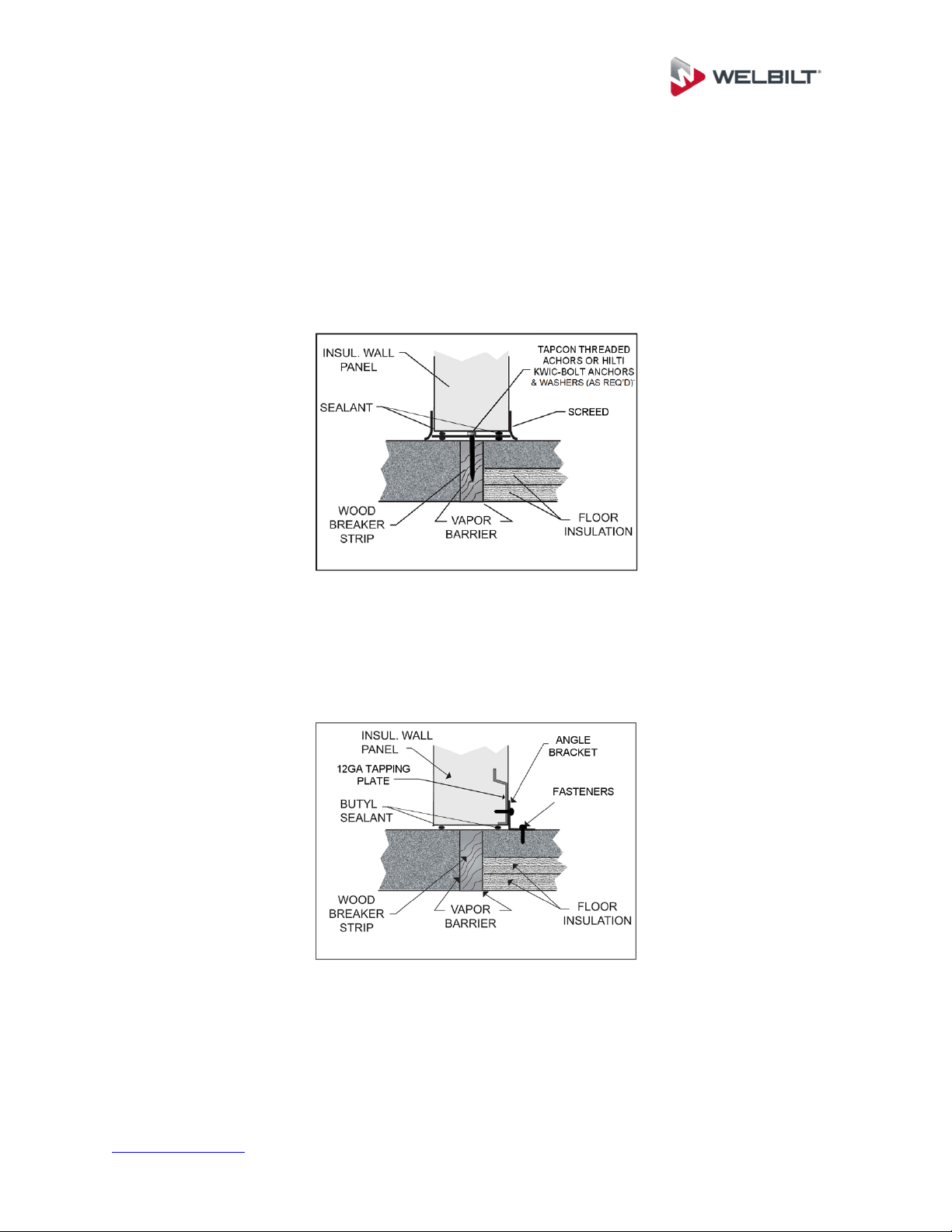
Flat-bottom walls are available for configurations that require a metal screed, do
not have an integral cove, and will be anchored by an exterior (or interior)
mounting angle. Mounting angles are supplied in 10’ lengths and field cut to fit
the dimensions of the enclosure as necessary.
Screed Installation
Place the screeds on the floor using the chalk lines as guides. Where factory cut
screed is used, screed sizes and layout are identified in the assembly drawings.
www.kolpak.com 800-225-9916 11
A thermal break (breaker strip) is required to separate all freezer interior concrete
from the exterior concrete. The interior freezer concrete floor must be insulated
and completely isolated. The screed/wall is to be centered over the thermal
break.
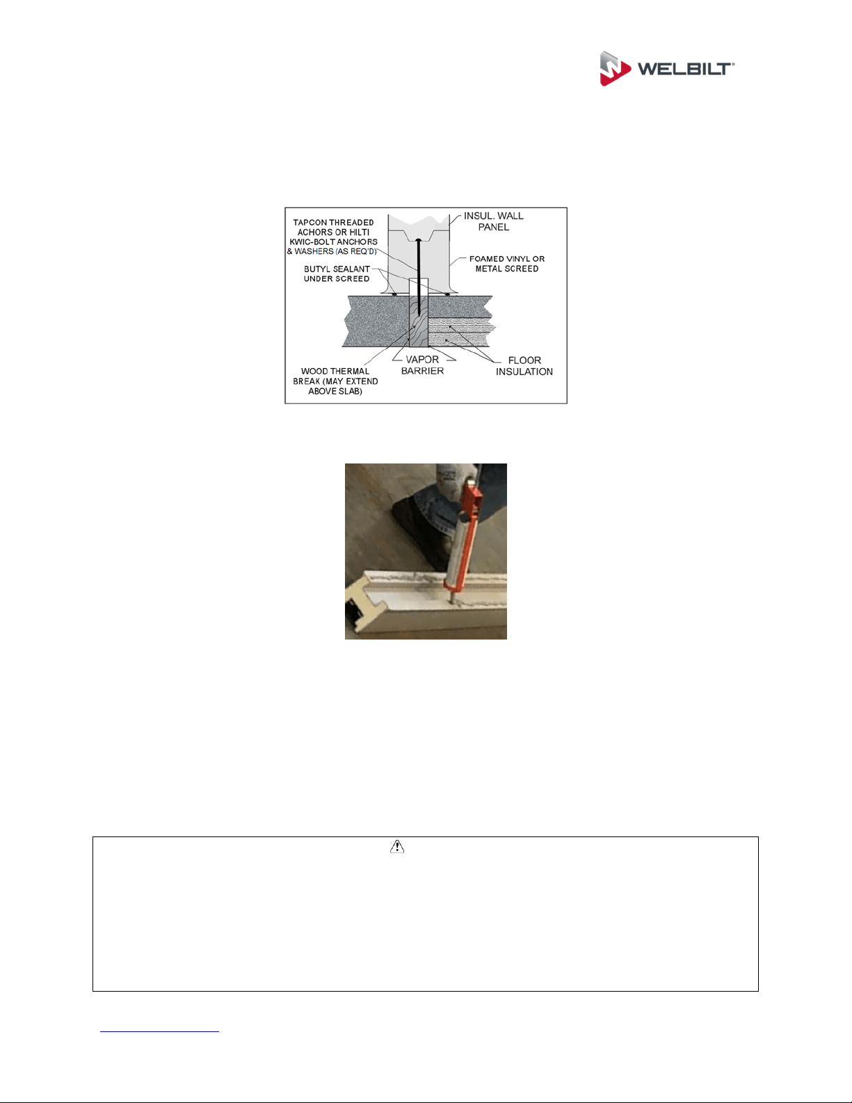
Apply two beads of non-drying butyl sealant to the bottom side of the screeds.
Start at back corner and fasten screeds in place for two adjoining walls. Fasten
screed as shown on assembly drawing with fasteners provided.
Each section of screed is to have a minimum of two fasteners, one on each end.
This is especially true for screed sections under the door. For long screed
sections, fasteners should be spaced at a maximum of four feet.
To insure proper fit, do not fasten screeds for remaining walls until the first two
walls are assembled.
CAUTION
Thermal breaks are required in freezer applications and recommended in cooler
applications to separate the interior flooring from the exterior floor. Thermal breaks
prevent heat transfer and increase energy efficiency.
A 3/8” bead of non-drying butyl sealant is required and should be continuous around the
complete perimeter of the walk-in. This sealant application will assist in maintaining the
vapor barrier.
www.kolpak.com 800-225-9916 13
Panels are labeled with numbers corresponding to those on the assembly drawing.
CAUTION
Stationary floor loads of up to 1000 pounds per square foot can be stored on Welbilt
standard floor panels and up to 5000 pounds per square foot can be stored on Welbilt
structural floor panels. If forklift trucks are used, special construction techniques must
be followed for concrete wear surfaces over the panels. Consult customer service for
recommendations.
Mark and level the floor according to site preparation requirements.
Lay out floor panels in correct sequence according to assembly drawings,
making sure the flooring is level.
Lock floor panels together, making sure edges are flush and square.

www.kolpak.com 800-225-9916 14
Flooring Overlay Installation
CAUTION
Installation of overlay material is best accomplished before the refrigeration system has
been started, and before any product has been loaded. In the event that overlay must
be added at a later date, ensure that the refrigeration system has been turned off and
that the subsurface has been allowed to return to a normal working temperature.
Installing at a low temperature may not allow the adhesive/sealant to cure adequately.
Clean and dry subsurface.
Apply silicone to the underside of flooring overlay material.
Begin laying first row of flooring overlay ½” away from the edge of the floor
according to the drawing and secure to the subsurface with sheet metals screws
or anchors.
All sheets must be as flush as possible to one another.
All sheets must be secured using a sheet metal screws or anchors every 24”.
Ensure that at least one fastener is used near each corner of the overlay
material.
Continue to follow the layout according to the drawing until all sheets are flush
and secured to the subsurface.
Caulk all seams and edges of flooring overlay material.
Allow 1-3 hours for the adhesive/sealant to dry prior to resuming use of the walk-
in.
www.kolpak.com 800-225-9916 15
Concrete & Tile Flooring
CAUTION
Gasses emitted by curing concrete floors or tile grout will damage panel finishes.
Adequate ventilation must be provided when the concrete floor or tile setting bed and
grout is curing. Leave all doors open for ventilation. If concrete or tile is to be installed
after walk-in is erected, protect the wall finish by applying a protective covering.
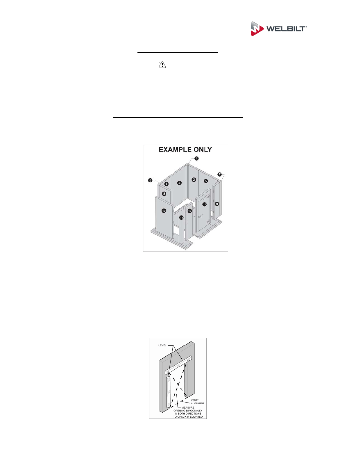
Wall Panels & Door Section Installation
Review the wall panel and door sections layout on the assembly drawing. Panels are
labeled with numbers corresponding to those on the assembly drawing.
Start with a back corner and work around the unit both ways, ending with a front
corner. Do not lock the walls into the floor/screed at this time.
Begin wall panel assembly by cam-locking a back corner panel and one wall
panel together. See assembly drawing for correct panel placement, and tongue
and groove directions.
Door sections will be installed in sequence along with wall panels. Use a level to
set the door section plumb and level.
www.kolpak.com 800-225-9916 16
Work around unit in both directions, ending at opposite corner.
Ensure the edges and tops of walls are flush.
Lock the wall panels and door section into the floor/screed.
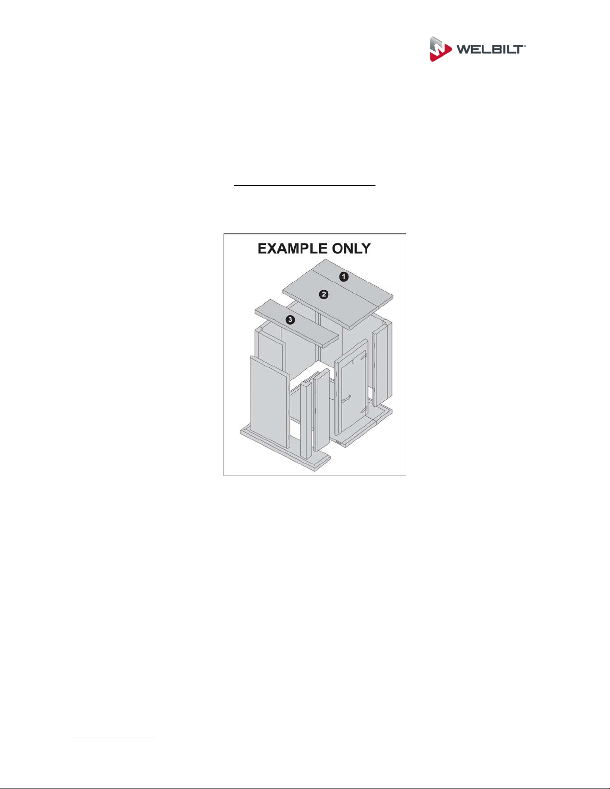
Ceiling Panel Installation
Review the ceiling panel layout on the assembly drawing. Panels are labeled with
numbers corresponding to those on the assembly drawing.
Use assembly drawings for correct panel placement and sequence.
Begin with an end section for a single compartment enclosure, or a tee panel for
a multi-compartment enclosure
Place ceiling panels in position, per the assembly drawings, on top of wall
panels. Do not lock ceiling panels to the wall at this time.
Check panel alignment.
Cam-lock ceiling panels together.
After several ceiling panels are in position and locked together, check all wall to
ceiling joints for flush fit and proper alignment.
Lock ceiling panels to wall panels.
www.kolpak.com 800-225-9916 17
WARNING
The top panels on walk-in units are designed, at a minimum, for an allowable live load
of ten pounds per square foot as noted on submittal drawings and installation
instructions. Top panels are not designed as work platforms or for dry storage and
should not be used as such. Use in such a manner could damage the structural
integrity of the top panels and will void the manufacturer’s warranty. Do not place
condensing units on top of ceiling panels.
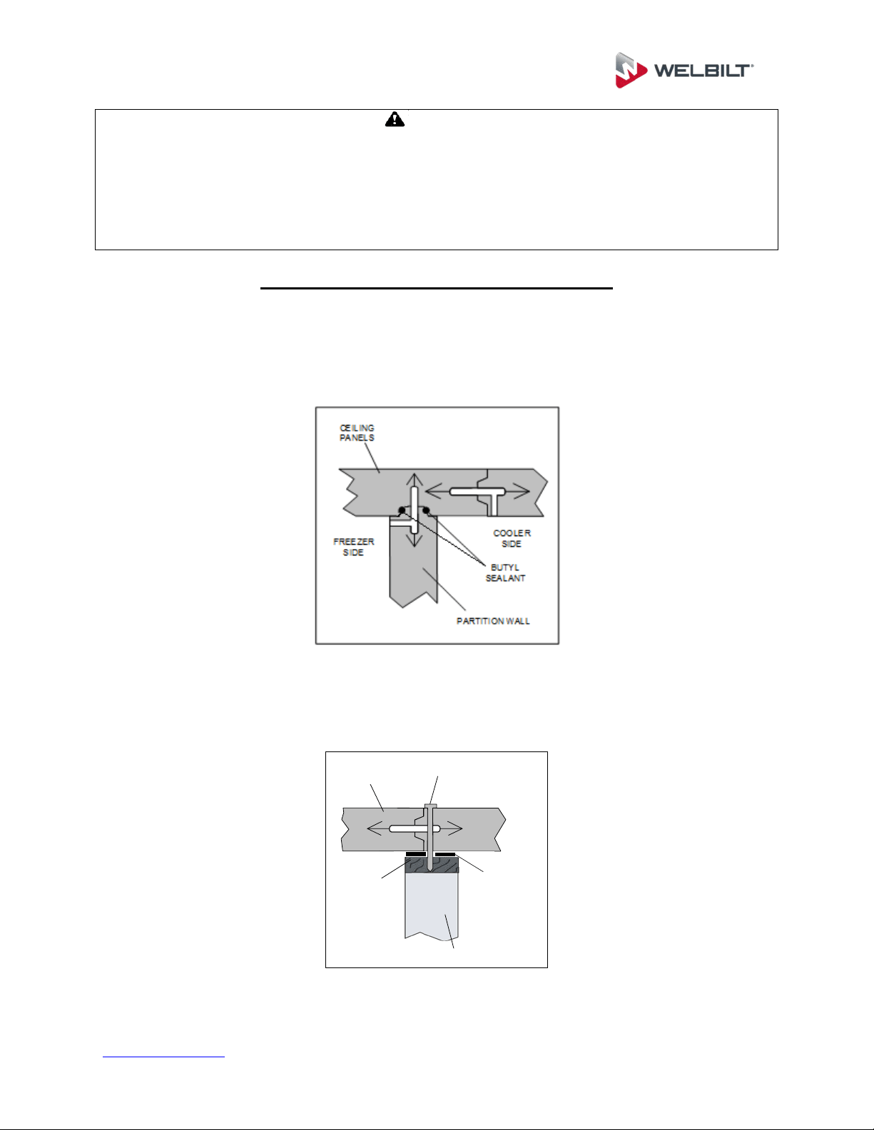
Split-Over Partition Wall Ceiling Installation
Indoor applications: Apply a continuous 3/8” bead of non-drying (butyl) sealant
to the both sides of the wall to ceiling joint. Lock ceiling panels together and
align over partition wall. Once all ceiling panels are assembled and aligned, lock
the wall to the ceiling.
Outdoor applications: Apply butyl tape to the partition wall anchor plate. Lock
ceiling panels together and align over partition wall. Once all ceilings are assembled
and aligned, attach lag bolts through the ceiling cam lock hole into the anchor plate.
3/8” LAG BOLTS THROUGH
MALE CAM LOCK HOLES
PARTITION WALL
ANCHOR
PLATE
CEILING
PANELS
BUTYL
REFRIGERATION
TAPE (SHIPPED
LOOSE)
www.kolpak.com 800-225-9916 18
CAUTION
Apply a continuous 3/8” bead of non-drying (butyl) sealant at all partition wall/ceiling
joints. Apply the sealant on both sides of the panel. This sealant application will assist
in maintaining the vapor barrier.
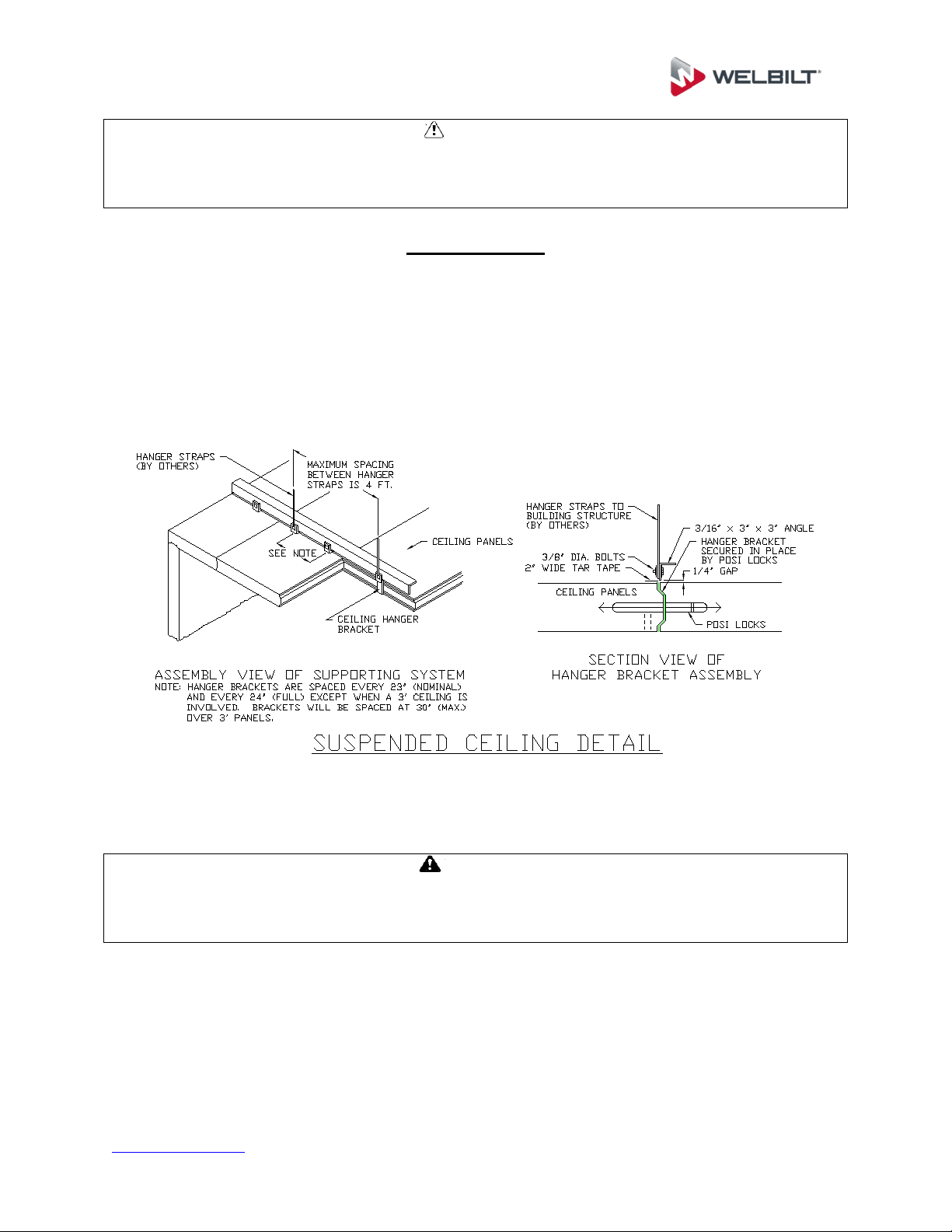
Ceiling Support
Indoor enclosures with dimensions of more than 14’-8” in both length and width must
have some type of support for the ceiling panels. Suspended ceiling hangers, foamed
in super ceiling channel, exterior self-support steel beams, or interior steel beams with
column supports must be used. Reference details provided on the as built drawing and
the diagram below for suspended ceiling support installation instructions.
WARNING
These systems must be installed properly in order to provide the necessary support for
the ceiling panels, allowing them to maintain their design load rating. Failure to do so
may result in an unsatisfactory installation, or an unsafe condition.
www.kolpak.com 800-225-9916 19
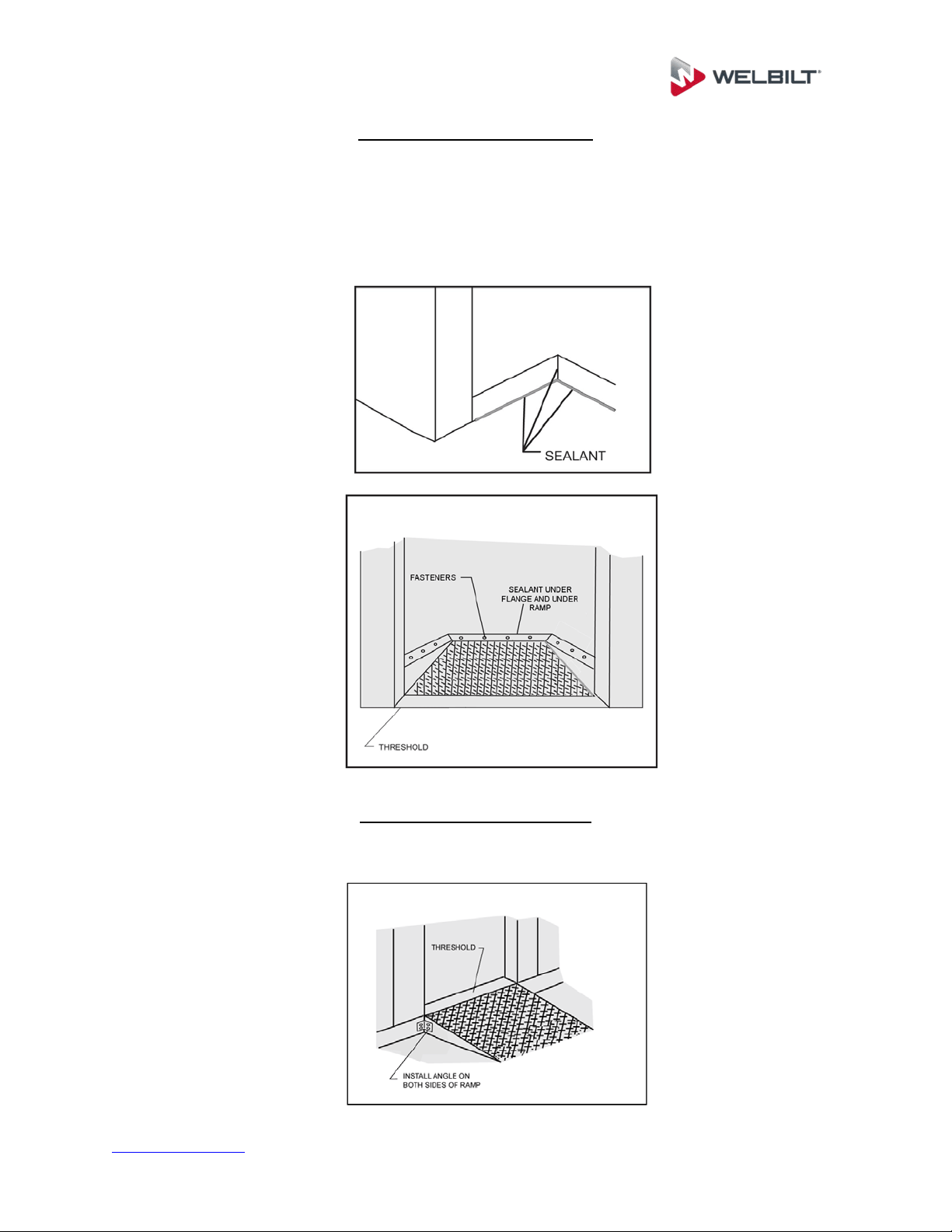
Interior Ramps Installation
Review the floor panel layout on the assembly drawing. Panels are labeled with
numbers corresponding to those on the assembly drawing.
Apply sealant at ramp cavity to concrete and floor intersections. Install ramp and
drive fasteners in place. Apply sealant to all ramp edges.
Exterior Ramp Installation
Install the exterior ramp and fasteners per the details provided on the assembly
drawing.
www.kolpak.com 800-225-9916 20
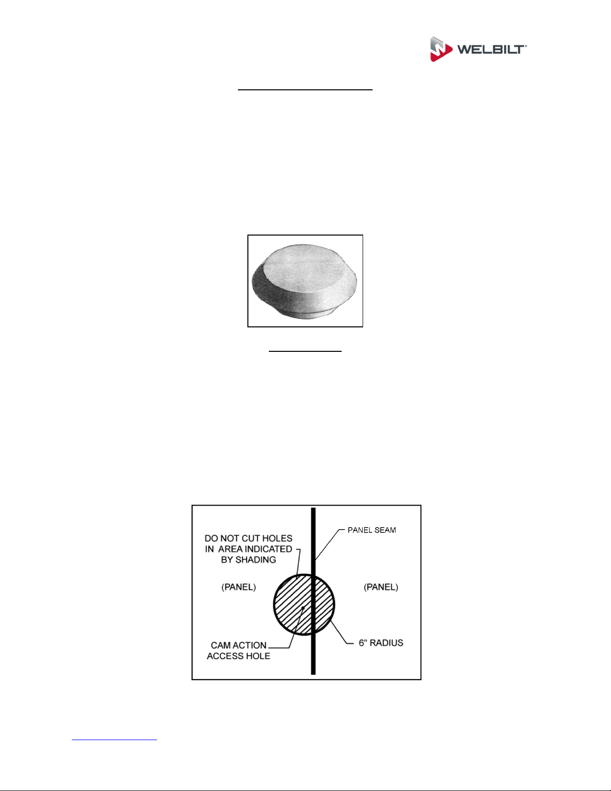
Plug Button Installation
Remove protective covering from panels, if applied.
Check that all cam locks are engaged.
Insert plug buttons into the cam lock wrench access holes and firmly tap in place
using a rubber mallet.
Plug buttons supplied for walls and ceilings are vinyl, plug buttons supplied for
floors are either stainless steel or high-strength plastic
Penetrations
Some areas of walk-in panels contain working parts and should not be
penetrated. Do not make a penetration within 2” of cam lock holes or panel
seams.
Penetrations must be completely sealed (insulation, foam, etc.) to prevent heat
transfer and condensation/ice formation. Electrical penetrations must be sealed
both internally and externally to form an acceptable seal.
Penetrations is outdoor ceilings is not permitted.
Trim and Wainscoting Material Installation
www.kolpak.com 800-225-9916 21
Trim and Wainscoting Material Installation
Install any trim provided per the assembly drawing. Reference the assembly drawing
for trim type and location.
All wainscoting material will be cut to size and shown on the assembly drawing.
Wainscoting material is numbered for easy identification.
CAUTION
Installation of wainscoting material is best accomplished before the refrigeration system
has been started, and before any product has been loaded. In the event that
wainscoting must be added at a later date, ensure that the refrigeration system has
been turned off and that the subsurface has been allowed to return to a normal working
temperature. Installing at a low temperature may not allow the adhesive/sealant to cure
adequately.
Clean and dry subsurface.
Follow the sequence of labels on the sheets of material in accordance to the
labeling on the assembly drawing.
Attach corner pieces (if applicable) first, by applying silicone adhesive to the back
side, and then securing to the panel walls using sheet metal screws every 24”.
The remaining sheets can then be secured using sheet metal screws every 24”.
Ensure that at least one fastener is used near each corner of each piece of
material.
All sheets must be as flush as possible to one another.
Make sure that all sheets make contact with outside finished floor.
Caulk all exposed edges of sheeting.
Allow 1-3 hours for the adhesive/sealant to dry prior to resuming use of the walk-
in.
www.kolpak.com 800-225-9916 22
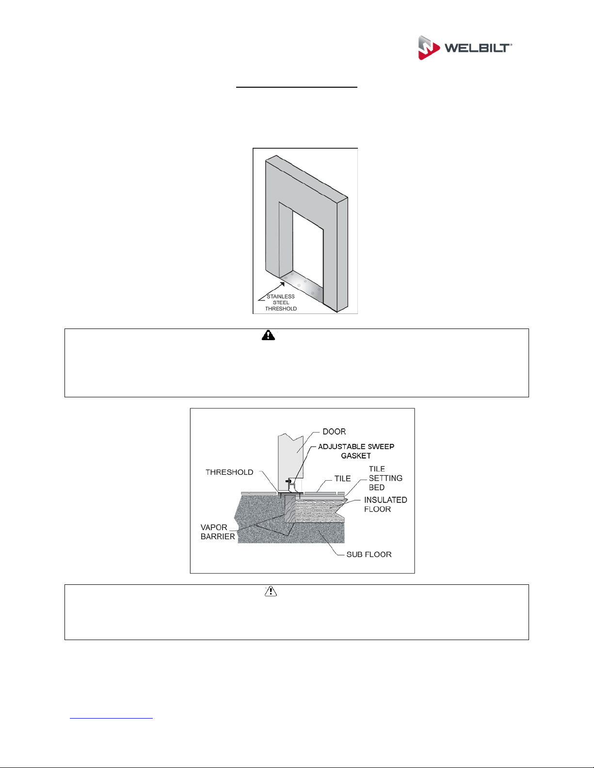
Threshold Installation
Install the threshold per the details provided on the assembly drawing. Threshold types
include fiberglass and stainless steel and are provided with either flat or sloped
transitions depending on the required floor application.
WARNING
Make sure that if any holes are drilled into the threshold, or when the fasteners are
driven, that they do not damage the threshold heater wire inside or under the threshold
assembly. Damage to this could impair the ability of the heater to melt any ice which
forms on the threshold, or could even result in an electrical short.
CAUTION
Do not extend tile and grout through the unit door opening. Any tile and grout on the
interior of a unit must be completely separated from tile and grout on the exterior to
prevent condensation issues and excessive heat loss.
www.kolpak.com 800-225-9916 23
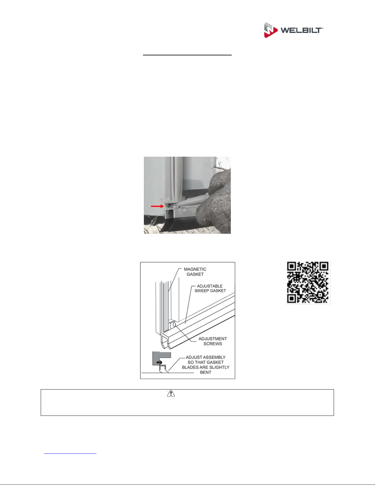
Door Sweep Adjustments
Check that door section is plumb and level.
Check operation of door, adjust door section if necessary.
Ensure the door gasket seals around the entire door perimeter.
Adjust wiper gasket to seal on floor/threshold.
If door sweep has been adjusted down, seal gap between the bottom of the door
gasket and the top of the door sweep.
Scan the QR Code below to view the Door Sweep Adjustment Service Video.
CAUTION
Ensure the exterior tile is level with the threshold throughout the entire door swing, to
prevent damage to the door sweeper gasket.
www.kolpak.com 800-225-9916 24
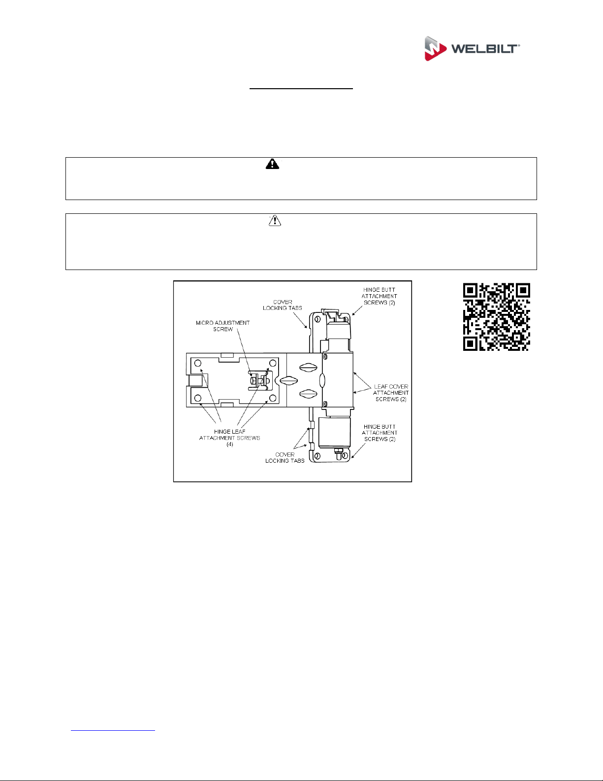
Adjustable Hinges
Some doors are equipped with adjustable hinges. Use the following procedure to
properly adjust the hinges if necessary. Scan the QR Code below for the Adjustable
Hinge Service Video.
WARNING
Never remove all hinge attachment screws without first securing the door or door
section to prevent it from falling over and injuring someone.
CAUTION
Care must be taken during hinge adjustment to ensure that the hinge attachment
fasteners are not over-torqued during reinstallation or retightening, as the underlying
door tapping plate could become stripped out.
Close the door completely, and remove the hinge leaf cover screws from all
hinge covers.
Loosen up all 4 hinge leaf attachment screws on each hinge slightly so that they
are free to move.
Install shims around the entire perimeter of the door. The goal is to perfectly
center the door in the opening.
Using a small wrench, or finger pressure, tighten the micro-adjustment screw on
each hinge until it is snug. Upper screws should be adjusted clockwise, lower
screws counter-clockwise.
Retighten all hinge leaf attachment screws for all hinges. Be sure not to over
torque the screws
Remove all of the shims, and check for door swing clearances and operation
If the misalignment has been corrected, replace the hinge leaf covers and
screws. If further adjustment is necessary, repeat the above steps using different
combinations of shims until the adjustment is completed.
www.kolpak.com 800-225-9916 25
Thermometer Testing
To test for thermometer accuracy, use a mixture of crushed ice and water to form a
slush. Place the thermometer bulb in the mixture and check the reading. Thermometer
should read approximately 32
o
F. If not, recalibrate per instructions. Thermometer
testing is a required part of installation to insure against calibration drift that may have
occurred during shipment. Once thermometer calibration is confirmed, the thermometer
bulb should be mounted away from the door opening.
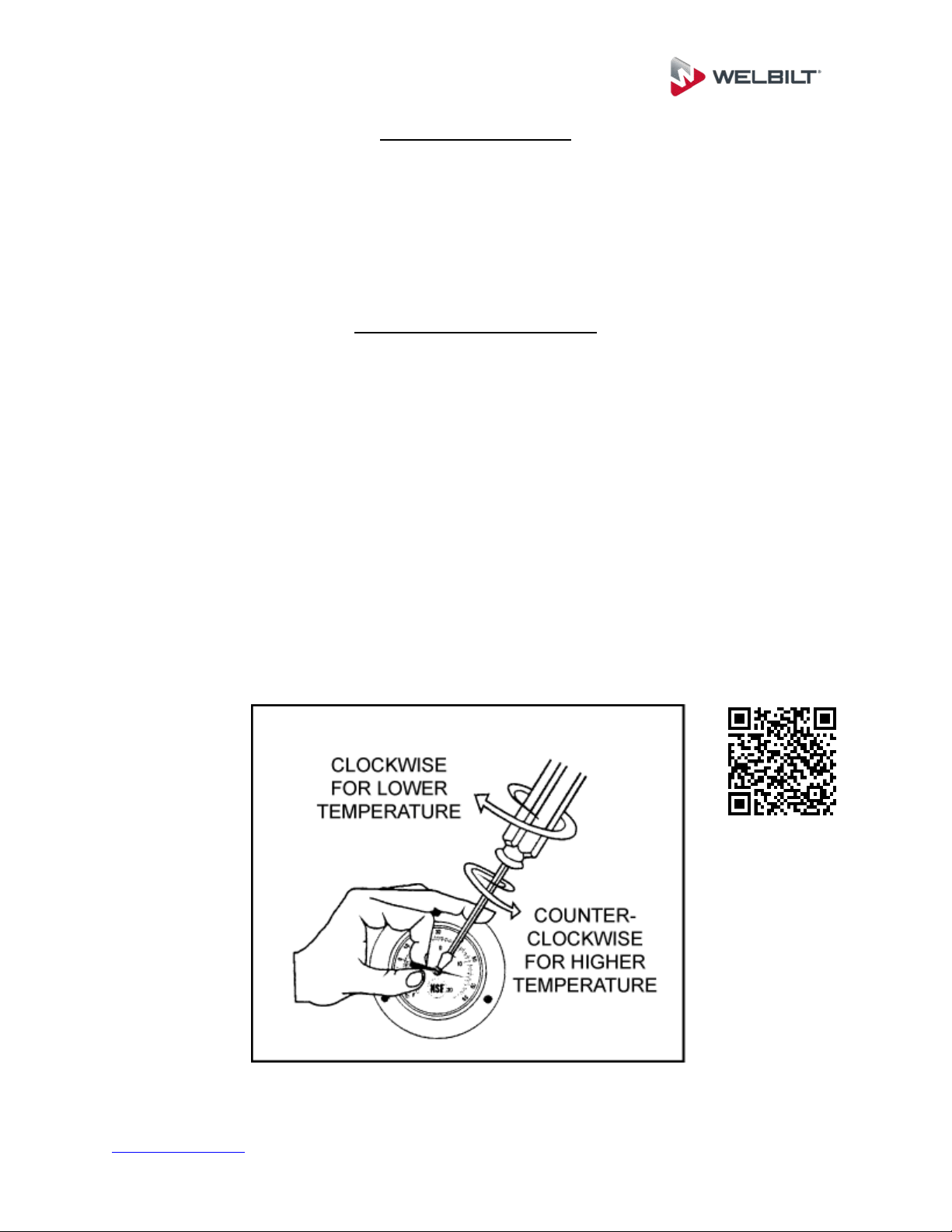
Thermometer Recalibration
Remove the face cover of the analog dial thermometer. The cover will either screw off
or pry off. Take care not to damage the cover during removal.
For lowering the reading, carefully hold the pointer. Insert screwdriver in pointer
slot and slowly turn clockwise a small amount. Adjust to proper setting.
For higher temperature reading, carefully hold the pointer. Insert the screwdriver
in pointer slot and slowly turn counter clockwise a small amount. Adjust to
proper setting.
Carefully reinstall the face of the thermometer.
Scan the QR Code below for the Thermometer Calibration Service Video.
www.kolpak.com 800-225-9916 26
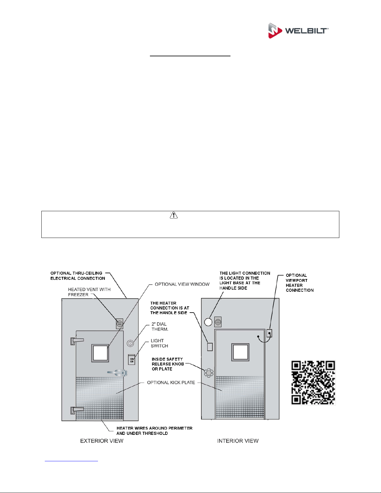
Electrical Connections
Consult the installation drawing supplied with the walk-in to determine which application
is required. Unless otherwise shown, the door section is furnished with a factory
installed vapor proof light fixture on the interior of the section, and a light switch with
pilot light indicator flush mounted on the exterior. All freezer door sections and cooler
doors with metal thresholds are equipped with anti-condensate heaters around the
entire perimeter. Heaters run underneath the thresholds, so care must be used if
drilling through so that the wire does not get damaged.
All wiring in the door and door section for heaters, switch, and light fixtures is factory
installed and requires only simple field connection for complete operation; typical
service required is 120 volt, 60 cycle, single phase, unless otherwise shown (consult the
installation drawing).
Electrical connections for the anti-condensate heaters are made on the interior of the
door section inside the fixture base of the vapor proof light. Consult the assembly
drawing for the specific electrical connection point for your unit.
CAUTION
Force sealant around wires in entrance conduit to prevent moisture from entering
fixture. Failure to eliminate airflow in conduit could void warranty.
For wiring diagrams, visit our website or scan the QR Code below.
www.kolpak.com 800-225-9916 27
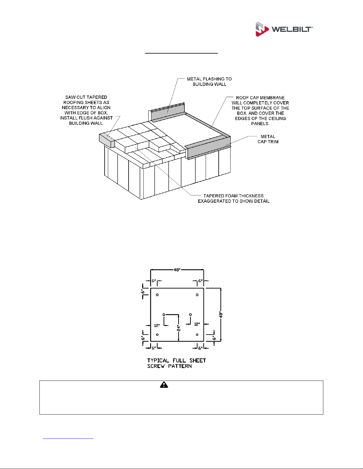
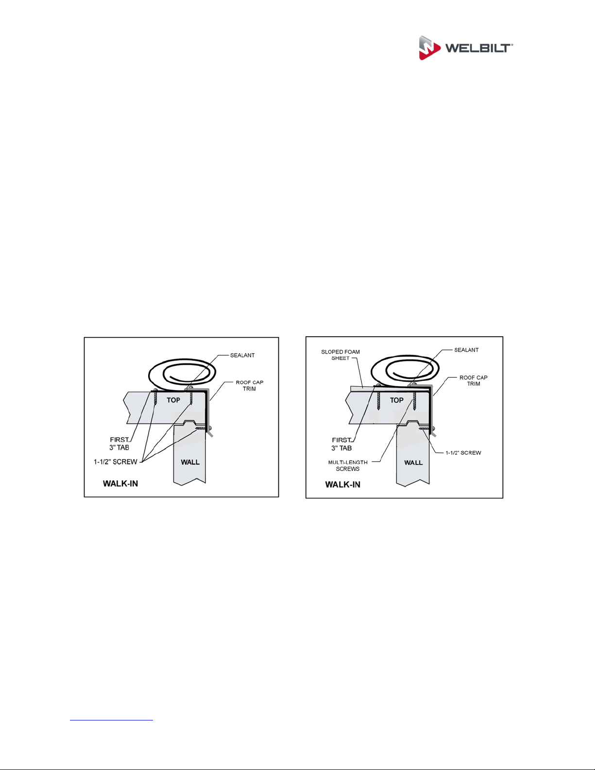
Tapered Roof System
The tapered roof system consists of tapered foam sheets, rolled polyethylene roof cap
membrane, flashing, roof cap trim, and fasteners. Installation is identical to standard
membrane roofs with the exception of adding the sloped foam sheets. In applications
with very large roofs, multiple layers of sloped foam may be required. For install
locations with a high wind speed rating per building code, extra fasteners will be
supplied so that the installer can use 6 fasteners and plates in each of the 4”x4” foam
sheet sections. The installer should use the fastener pattern shown below.
WARNING
Building codes require a minimum of ¼ inch per foot slope on outside roof systems. If a
tapered roof system is not purchased with an exterior walk-in, it is the purchaser’s
responsibility to ensure this requirement is met.
www.kolpak.com 800-225-9916 28
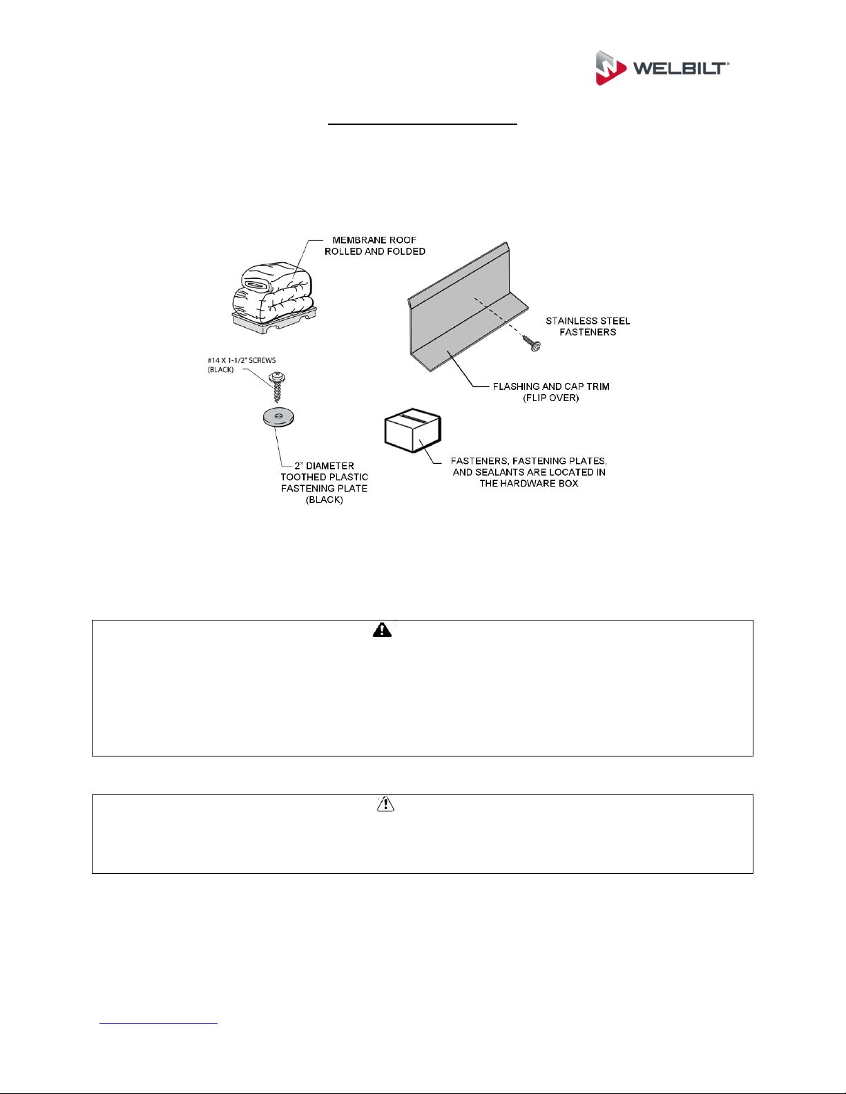
Membrane Roof System
Locate the parts required for the installation of the membrane roof. The membrane roof
is shipped rolled and folded. The termination bar and any roof trim required are shipped
in 6” diameter by 10’ long cardboard tubes. A hardware box containing screws,
fastening plates and sealant is also included.
Check the roof of the walk-in unit and remove any foreign matter. Seal all
protruding rough edges and screw heads, rivets, etc. with tape or sealant. This
will prevent any chance of penetrating or wearing a hole in the membrane roof
cap.
WARNING
Make sure that all safety precautions are taken as necessary to prevent anyone working
on the roofing installation from falling off from the top of the unit.
Ceiling panels are not intended for walking traffic or any other loads. Ensure that during
install, a lift or boom is used to support installers and equipment weight, so that the
extra loads are not supported by the ceiling panels.
CAUTION
Make sure that any debris is removed from the top of the unit before installing any
roofing materials, as damage may occur to the membrane roof cap if installed over a
sharp object.
www.kolpak.com 800-225-9916 29
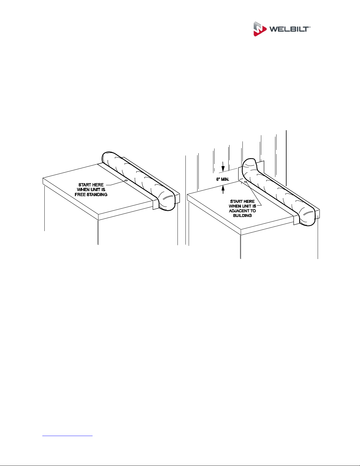
Install the sloped foam sheeting (if required) first. Consult the “As Built” drawing
for proper placement. Locate the thickest tapered sheets and install them flush
to the building wall, working toward the furthest edge with progressively thinner
sheets.
If the unit is free standing, align the thickest panel along the side of the ceiling
panel.
Verify the overall width and length of the membrane by measuring the sloped (of
flat) dimension on top of the unit, and compare to the printed size on the rolled
membrane. The membrane should overhang the top edge of the wall panel by 5”
on all exposed sides of the walk-in unit, and extend at least 8” up on adjacent
building walls.
The smooth (shiny) finish surface of the membrane is the exposed (up) side.
The 3” fastening tabs are on the bottom side of the membrane.
Unroll roof membrane and align first 3” tab with a square chalk line across the
unit. Use a GRiPull roof puller racket vice grip tool to pull membrane taut.
Fasten 3” tab by using 1 ½” black #14 screw and fastening plate. Align
membrane so that the tabs are perpendicular to the adjacent building.
Start in the middle of the tab and work toward the edges placing the screws and
plates 6” on center. Pull membrane toward edges to remove slack. The 1-1/2”
screws should penetrate the top metal skin of the walk-in top panel.
www.kolpak.com 800-225-9916 30
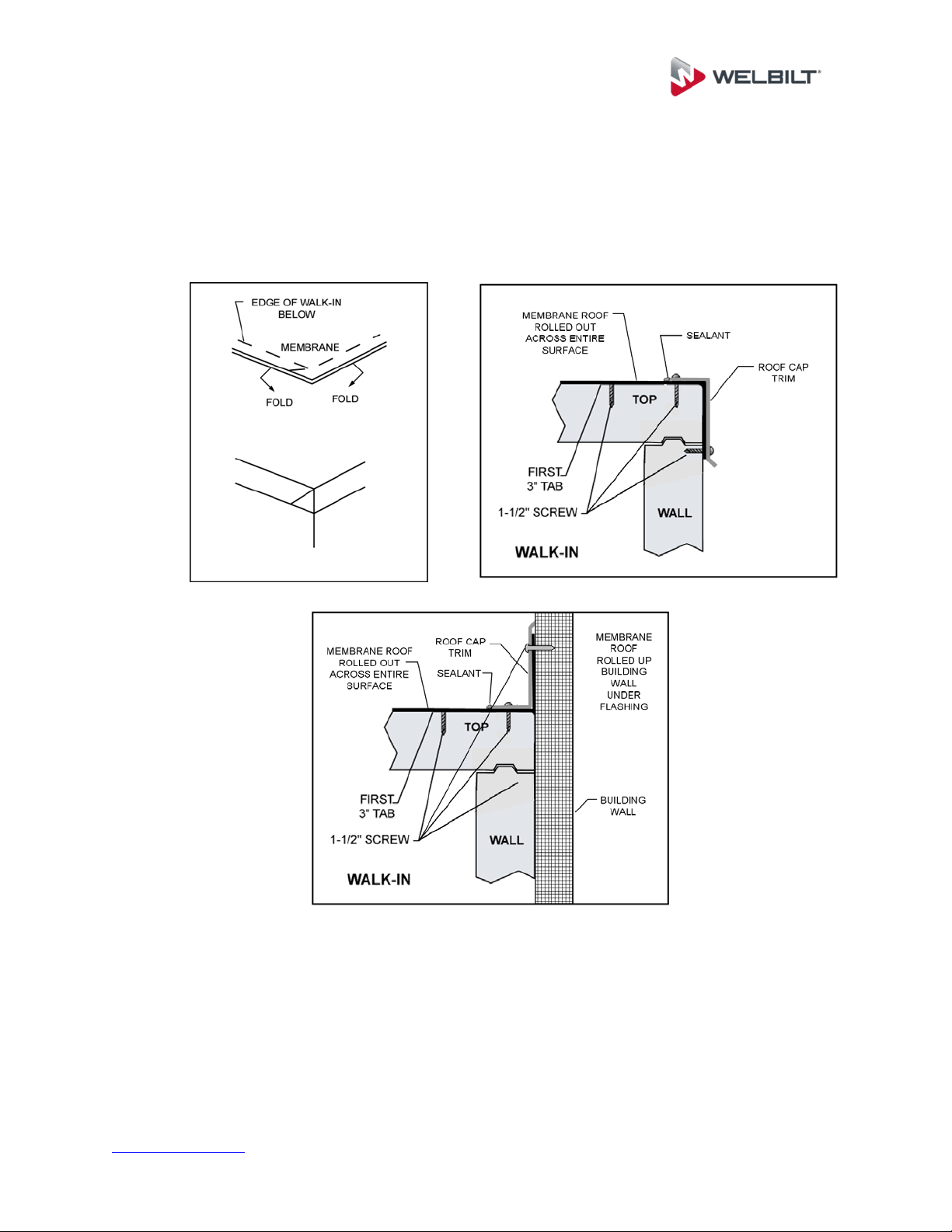
Start at the base of the wall by fastening a plate into the top of the walk-in cooler
and into the wall of the adjacent building. Make sure at least 8” of material is up
the wall for proper termination. Work away from wall fastening 6” on center. The
1-1/2” screws should penetrate the top metal skin of the walk-in top panel.
If tapered roof system is used, the screw length will vary. Install the short screws
at the low side and increasingly longer screws toward the high side. Extra care
should be taken to only penetrate the top metal skin of the walk in top panel. Do
not penetrate the interior metal skin.
To prevent “Tab Rollover”, temporarily secure the edge of the overhanging roof
membrane to the top edge of the wall before continuing to the second tab
Unroll roof cap membrane to next tab and repeat the screw and fastening plate
pattern. Always pull slack out of membrane before starting a row of fasteners.
Use of GRiPull roof puller racket vice grip tool is ideal to keep material taut.
www.kolpak.com 800-225-9916 31
After all fastening tabs have been secured, fold corners as shown. A Pull-Tite
hand/knee puller vice grip tool can be used to pull membrane taut around
perimeter and then install roof cap termination bar and trim. Use 1-1/2” stainless
steel screws spaced 6” on center. Seal top edge of termination bar.

www.kolpak.com 800-225-9916 32
Maintenance and Housekeeping Recommendations
WARNING
Walk-in floors can become slippery and hazardous if allowed to become wet, greasy, or icy.
Follow maintenance and housekeeping recommendations outlined below to minimize any
hazards.
Inspect the conditions of abrasive coated anti-skid strips on ramps monthly.
Replace or add additional strips when necessary. Abrasive coated anti-skid
strips are factory installed on ramps. Additional strips are available from the
factory.
Keep all walkway surfaces clean and free of spilled liquids and food particles.
This includes the floor surface, hardwood floor racks, and diamond tread plate.
Inspect refrigeration equipment frequently for proper functioning of evaporators,
drain pan heaters, defrost controls, and drain line heaters. Refer to
manufacturers' instructions for the refrigeration system.
Condensate water must never be allowed to drip on the walk-in floor. Refer to
refrigeration system instructions for proper condensate drain line installation.
If entry doors are to be held open for periods longer than 5 minutes, a vinyl strip
curtain should be used. When doors are opened for extended periods of time,
frost can form on the ceiling and floor due to the excessive condensation of warm
moist air inside the walk-in. This can result in the formation of an ice film on wall,
ceiling and floor surfaces or around gaskets.
Inspect the door hardware and sweep gasket monthly for ease of operation.
Door hardware is self-lubricating and does not require periodic lubrication.
Sweep gasket must be adjusted to allow free movement and proper seal. Any
damaged hardware should be replaced immediately to prevent permanent
damage to the door.
Frost or condensation appearing around the door jamb or heated pressure relief
vent indicates that the electric heater is inoperable, or excessive moisture is
present. Check power supply and electrical connections. Replace heaters if
necessary.
All metal surfaces, magnetic door gaskets and door sweep gaskets should be
cleaned frequently with a mild detergent and hot water. Remove all soap film
and dry thoroughly with a clean cloth. Never use high pressure hose or large
amounts of water to clean walk-in.
www.kolpak.com 800-225-9916 33
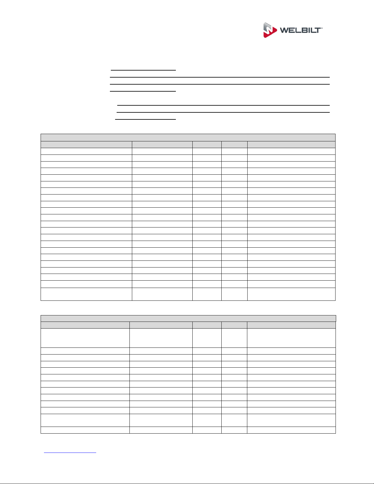
System Start-up Checklist
Date System Installed: / /
Installer and Address:
Phone Number: ( ) -
Start-Up Service Agency:
Phone Number: ( ) -
Freezer Condensing Unit
Inspection Feature
Data
Accept
Reject
Action Required
Model Number:
Serial Number:
Electrical Volts:
Electrical Phase:
Amperage @ L1:
Amperage @ L2:
Amperage @ L3:
Ambient Temp:
°F
Comp. Discharge Pressure:
PSIG
Comp. Suction Pressure:
PSIG
Suction Line Temp @ Comp.:
°F
Discharge Line Temp @ Comp.:
°F
Comp. Superheat:
°F
Defrost Setting (4 day/45 min):
All electrical connections are tight:
Unit base properly supported:
Fans Running & No Vibration:
All guards, covers attached:
Refrigerant Sight Glass Clear:
Comp. Oil Level @ ½ Sight Glass:
Comp. Mounting Clips Removed:
Suction line insulated fully and
properly supported:
Freezer Evaporator
Inspection Feature
Data
Accept
Reject
Action Required
Evaporator installed with nylon
bolts with proper airflow
clearance:
Model Number:
Serial Number:
Electrical Volts:
Electrical Phase:
Suction Line Temp @ Evap:
°F
Evap Superheat:
°F
Thermostat Set:
°F
Operating Temp:
°F
TXV Bulb Properly Mounted:
All guards, covers attached:
All electrical connections are
tight:
Defrost Heater Amp Draw:
A
www.kolpak.com 800-225-9916 34
Freezer Piping
Inspection Feature
Data
Accept
Reject
Action Required
Suction Lines Insulated:
Oil Trap at Base of Suction Riser:
Copper Drain Lines Sloped Min
1/2” ft:
Piping Supported Every 5’:
Copper drain line heater
attached, working, and insulated:
Copper Drain Line Trapped
Outside Freezer Space:
Cooler Condensing Unit
Inspection Feature
Data
Accept
Reject
Action Required
Model Number:
Serial Number:
Electrical Volts:
Electrical Phase:
Amperage @ L1:
Amperage @ L2:
Amperage @ L3:
Ambient Temp:
°F
Comp. Discharge Pressure:
PSIG
Comp. Suction Pressure:
PSIG
Suction Line Temp @ Comp.:
°F
Discharge Line Temp @ Comp.:
°F
Comp. Superheat:
°F
Defrost Setting (4 day/45 min):
All electrical connections are tight:
Unit base properly supported:
Fans Running & No Vibration:
All guards, covers attached:
Refrigerant Sight Glass Clear:
Comp. Oil Level @ ½ Sight Glass:
Comp. Mounting Clips Removed:
Suction line insulated fully and
properly supported:
Cooler Evaporator
Inspection Feature
Data
Accept
Reject
Action Required
Evaporator installed with nylon
bolts with proper airflow
clearance:
Model Number:
Serial Number:
Electrical Volts:
Electrical Phase:
Suction Line Temp @ Evap:
°F
Evap Superheat:
°F
Thermostat Set:
°F
Operating Temp:
°F
TXV Bulb Properly Mounted:
All guards, covers attached:
All electrical connections are
tight:
www.kolpak.com 800-225-9916 35
Cooler Piping
Inspection Feature
Data
Accept
Reject
Action Required
Suction Lines Insulated:
Oil Trap at Base of Suction Riser:
Copper Drain Lines Sloped Min
1/2” ft:
Copper Drain Lines Insulated:
Copper Piping Supported Every
5’:
Copper Drain Line Trapped
Outside Cooler Space:
Walk-In Freezer
Inspection Feature
Data
Accept
Reject
Action Required
Serial Number:
Interior Lights Installed and
Working:
All Penetrations Sealed:
Doors/Jambs Squared and
Operating Properly:
All Panel Locks Fully
Engaged:
All Plug Buttons Installed:
Door Heater Working:
Door Sweeps Adjusted:
Heat Air Vent Working:
Door Closers Adjusted and
Working:
Wainscot and Trim Installed:
Alarm Set and Working:
Thermometer Bulb Mounted
and Calibrated:
Walk-In Clean (no excessive
caulk, etc.)
Walk-in at proper
temperature:
Walk-In Cooler
Inspection Feature
Data
Accept
Reject
Action Required
Serial Number:
Interior Lights Installed and
Working:
All Penetration Sealed:
Doors/Jambs Squared and
Operating Properly:
All Panel Locks Fully Engaged:
All Plug Buttons Installed:
Door Heater Working:
Door Sweeps Adjusted:
Heat Air Vent Working:
Door Closers Adjusted and
Working:

www.kolpak.com 800-225-9916 36
Wainscot and Trim Installed:
Alarm Set and Working:
Thermometer Bulb Mounted
and Calibrated:
Walk-In Clean (no excessive
caulk, etc.)
Walk-in at proper temperature:
Notes:
Superintendent/Customer Signature: ____________________________ Date: ______________
Service Tech/Installer Signature: ________________________________ Date: ______________
www.kolpak.com 800-225-9916 37
Warranty Information
Kolpak warranty only applies to the United States, Canada and Latin America.
Warranty claims outside of these regions must be approved by Kolpak prior to start of
repair. For warranty information, visit our website or scan the QR Code below.
The System Start-up Checklist will be required to be completed and returned to Kolpak
before warranty is valid. Email completed checklists to kpr-warranty@welbilt.com .
For any additional information regarding warranty guidelines, claim form, product
registration, warranty verification, service videos or locating a service provider please
visit our website at www.kolpak.com or call 1-800-225-9916.