
Loading ...
Loading ...
Loading ...
EVID
TM
Owner’s Manual
8
Product Description
Step-by-Step Installation
and Wiring (12.1
Subwoofer)
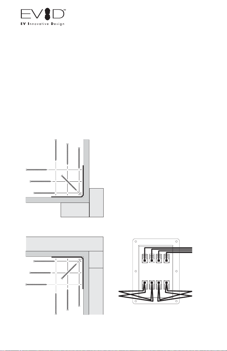
Step 1: Mount the Bracket
The mounting bracket can be installed two
ways (see Figures 20 and 21), allowing
optimal configurations for installations.
Leave 1.5" of space between the
bracket and the ceiling when installing
in a corner!
Attach the bracket to the wall with suitable
fasteners screwed into structural members
in the wall. Remember: It is the
installer's responsibility to insure that
the structure can safely support the
load.
Step 2: Install the Safety Line
Using accepted safe rigging practices,
secure one end of a suitable safety line
(use cable, not chain, which will rattle) to a
strong, secure point above the speaker, a
point that can withstand the shock of the
falling speaker. This is especially
important in public spaces constructed
with light-gauge steel studs. Do not
attach the safety line to the bracket! The
safety line should prevent the speaker
from falling if the bracket tears loose from
the wall. Secure the other end to the
eyebolt that is fully threaded into the
enclosure.
Step 3: Wire the Speaker
The amplifier and satellite speakers are
wired as shown in Figure 22. It is highly
advisable to support the unit while these
connections are being made. Connect all
wires to the speaker at the back terminal
plate observing proper polarity of the
connections. The push-terminals accept
stranded wire up to 14 gauge. When using
two satellites, wire the speakers directly
into the output terminals of the panel. Four
satellites may be connected either as two
pairs directly to the output terminals or
with daisy-chain wiring as in Figure 23.
Figure 20: Corner Installation (Top
View)
Figure 21: Midwall Installation (Side
View)
Figure 22: Direct Wiring Plan
Stud
Wall
Use a
mimimum of
four screws
Bracket
Wall
Stud
Stud
Wall
U
se a
m
imimum of
f
our screws
Ceiling Bracket
Joist
To p
plate
- L +
- L +
- R +
- R +
from
amplifier
to speakers
L
eft 1 Right 1
Right 2
L
eft 2
Loading ...
Loading ...
Loading ...